Embed Size (px)
Citation preview

Installation
and
Diagnostics Guide
for
µAutolab type II Autolab with PGSTAT10 Autolab with PGSTAT12 Autolab with PGSTAT30
Autolab with PGSTAT100
with USB support
Eco Chemie B.V. P.O. Box 85163
3508 AD Utrecht The Netherlands
Copyright 2001 Eco Chemie


Table of contents 3
Table of contents TABLE OF CONTENTS.......................................................................................................................................3
1. HOW TO USE THIS GUIDE............................................................................................................................7
2. INTRODUCTION..............................................................................................................................................9
3. INSTALLATION OF THE INTERFACE .....................................................................................................11
3.1 USB INTERFACE ...............................................................................................................................................11 Computer requirements......................................................................................................................................11 Connecting the Autolab-USB Interface box .......................................................................................................11 Connecting the Autolab-USB (Internal).............................................................................................................12
3.2 ISA - IF020 INTERFACE ....................................................................................................................................13 Computer requirements......................................................................................................................................13 Inserting the interface board..............................................................................................................................13 Configuring the interface board.........................................................................................................................13
4. INSTALLING THE SOFTWARE..................................................................................................................17
4.1 INSTALLATION OF THE AUTOLAB SOFTWARE.....................................................................................................17 4.2 USB DRIVER INSTALLATION..............................................................................................................................22
Installing the USB Driver for Windows 98 ........................................................................................................23 Installing the USB Driver for Windows Me .......................................................................................................30 Installing the USB Driver for Windows 2000 ....................................................................................................33
5. µAUTOLAB TYPE II ......................................................................................................................................37
5.1 FRONT PANEL CONTROLS AND CONNECTIONS....................................................................................................37 5.2 NOISE................................................................................................................................................................37 5.3 REAR PANEL CONNECTIONS FOR ANALOG SIGNALS............................................................................................38 5.4 HIGH SPEED AND HIGH STABILITY ....................................................................................................................38 5.5 RE INPUT IMPEDANCE AND STABILITY...............................................................................................................38 5.6 MAXIMUM REFERENCE ELECTRODE VOLTAGE...................................................................................................39 5.7 ACTIVE CELLS ...................................................................................................................................................39 5.8 GROUNDED CELLS.............................................................................................................................................39 5.9 ENVIRONMENTAL CONDITIONS..........................................................................................................................40 5.10 CLEANING AND INSPECTION ............................................................................................................................40
6. AUTOLAB WITH PGSTAT10.......................................................................................................................41
6.1 FRONT PANEL CONTROLS AND CONNECTIONS....................................................................................................41 6.2 NOISE................................................................................................................................................................41 6.3 REAR PANEL CONNECTIONS FOR ANALOG SIGNALS............................................................................................42 6.4 HIGH SPEED AND HIGH STABILITY ....................................................................................................................42 6.5 RE INPUT IMPEDANCE AND STABILITY...............................................................................................................42 6.6 MAXIMUM REFERENCE ELECTRODE VOLTAGE...................................................................................................43 6.7 ACTIVE CELLS ...................................................................................................................................................43 6.8 GROUNDED CELLS.............................................................................................................................................43 6.9 ENVIRONMENTAL CONDITIONS..........................................................................................................................44 6.10 FRONT PANEL CONTROLS ................................................................................................................................44 6.11 CLEANING AND INSPECTION ............................................................................................................................44
7. AUTOLAB WITH PGSTAT12.......................................................................................................................45
7.1 FRONT PANEL AND CELL CABLE CONNECTIONS .................................................................................................45 7.2 NOISE................................................................................................................................................................45 7.3 CONNECTIONS FOR ANALOG SIGNALS................................................................................................................46 7.4 HIGH SPEED AND HIGH STABILITY ....................................................................................................................46 7.5 RE INPUT IMPEDANCE AND STABILITY...............................................................................................................47

4 Installation and Diagnostics Guide
7.6 GALVANOSTATIC FRA MEASUREMENTS ...........................................................................................................47 7.7 GALVANOSTAT AND IR-COMPENSATION BANDWIDTH .......................................................................................48 7.8 OSCILLATION DETECTION..................................................................................................................................48 7.9 MAXIMUM REFERENCE ELECTRODE VOLTAGE...................................................................................................49 7.10 ACTIVE CELLS .................................................................................................................................................49 7.11 GROUNDED CELLS...........................................................................................................................................49 7.12 ENVIRONMENTAL CONDITIONS........................................................................................................................49 7.13 TEMPERATURE OVERLOAD..............................................................................................................................50 7.14 FRONT PANEL CONTROLS ................................................................................................................................50 7.15 ECD MEASUREMENTS.....................................................................................................................................50 7.16 CLEANING AND INSPECTION ............................................................................................................................51
8. AUTOLAB WITH PGSTAT30.......................................................................................................................53
8.1 FRONT PANEL AND CELL CABLE CONNECTIONS .................................................................................................53 8.2 NOISE................................................................................................................................................................53 8.3 CONNECTIONS FOR ANALOG SIGNALS................................................................................................................53 8.4 HIGH SPEED AND HIGH STABILITY ....................................................................................................................54 8.5 RE INPUT IMPEDANCE AND STABILITY...............................................................................................................55 8.6 GALVANOSTATIC FRA MEASUREMENTS ...........................................................................................................55 8.7 GALVANOSTAT AND IR-COMPENSATION BANDWIDTH .......................................................................................56 8.8 OSCILLATION DETECTION..................................................................................................................................56 8.9 MAXIMUM REFERENCE ELECTRODE VOLTAGE...................................................................................................57 8.10 ACTIVE CELLS .................................................................................................................................................57 8.11 GROUNDED CELLS...........................................................................................................................................57 8.12 ENVIRONMENTAL CONDITIONS........................................................................................................................57 8.13 TEMPERATURE OVERLOAD..............................................................................................................................58 8.14 FRONT PANEL METER ......................................................................................................................................58 8.15 FRONT PANEL CONTROLS ................................................................................................................................58 8.16 ECD MEASUREMENTS.....................................................................................................................................58 8.17 CLEANING AND INSPECTION ............................................................................................................................59
9. AUTOLAB WITH PGSTAT100.....................................................................................................................61
9.1 SUGGESTIONS FOR SETTING UP THE MEASUREMENT SITE...................................................................................61 9.2 SUGGESTIONS FOR TRAINING THE OPERATOR ....................................................................................................61 9.3 HOW TO MAKE SAFE CONNECTIONS TO A CELL..................................................................................................62 9.4 DISCHARGING CAPACITIVE CELLS......................................................................................................................62 9.5 FRONT PANEL AND CELL CABLE CONNECTIONS .................................................................................................62 9.6 NOISE................................................................................................................................................................63 9.7 CONNECTIONS FOR ANALOG SIGNALS................................................................................................................64 9.8 HIGH SPEED AND HIGH STABILITY ....................................................................................................................64 9.9 RE INPUT IMPEDANCE AND STABILITY...............................................................................................................65 9.10 GALVANOSTATIC FRA MEASUREMENTS .........................................................................................................65 9.11 GALVANOSTAT AND IR-COMPENSATION BANDWIDTH .....................................................................................65 9.12 OSCILLATION DETECTION................................................................................................................................66 9.13 MAXIMUM REFERENCE ELECTRODE VOLTAGE.................................................................................................66 9.14 ACTIVE CELLS .................................................................................................................................................67 9.15 GROUNDED CELLS...........................................................................................................................................67 9.16 ENVIRONMENTAL CONDITIONS........................................................................................................................67 9.17 TEMPERATURE OVERLOAD..............................................................................................................................67 9.18 FRONT PANEL METER ......................................................................................................................................68 9.19 FRONT PANEL CONTROLS ................................................................................................................................68 9.20 ECD MEASUREMENTS.....................................................................................................................................68 9.21 CLEANING AND INSPECTION ............................................................................................................................69
10. EXTENDED DUMMY CELL.......................................................................................................................71
11. ADDITIONAL MODULES...........................................................................................................................73

Table of contents 5
11.1 LOW CURRENT MODULE ECD .........................................................................................................................73 11.2 BIPOTENTIOSTAT MODULE BIPOT ..................................................................................................................73 11.3 MODULE FOR IMPEDANCE MEASUREMENTS FRA............................................................................................73 11.4 SCAN GENERATOR SCAN-GEN......................................................................................................................74
Front panel indicators .......................................................................................................................................74 Front panel connections.....................................................................................................................................74 Scan rates, vertex potentials, vertex count .........................................................................................................74 Digital control....................................................................................................................................................74
11.5 FAST AD-CONVERTER ADC750 .....................................................................................................................75 11.6 FILTER - INTEGRATOR MODULE FI20 ..............................................................................................................75 11.7 MODULE TO CONNECT ION SELECTIVE ELECTRODES PX .................................................................................75 11.8 MODULE TO MEASURE ELECTROCHEMICAL NOISE ECN..................................................................................76 11.9 MULTIPLEXING MODULE MUX .......................................................................................................................77
SCNR and MULTI units .....................................................................................................................................77 Connections........................................................................................................................................................77 Limitations .........................................................................................................................................................78
11.10 ARRAY........................................................................................................................................................78
12. ADDITIONAL EQUIPMENT ......................................................................................................................79
12.1 BOOSTER BSTR10A OR BSTR20A................................................................................................................79 12.2 ANY EQUIPMENT WITH -10..10 V OUTPUT (SECOND SIGNAL) ..........................................................................80 12.3 INTERFACE TO MERCURY ELECTRODES IME663, IME303.............................................................................80
Metrohm 663 VA Stand ......................................................................................................................................80 EG&G PAR303 ..................................................................................................................................................81 DME...................................................................................................................................................................81
12.4 MOTORBURETTES ...........................................................................................................................................81 Metrohm Dosimat 665 or 765 ............................................................................................................................81 Schott T100/T90 .................................................................................................................................................81
12.5 EXTERNAL ROTATING DISK ELECTRODE (RDE) .............................................................................................81
13. CONFIGURATION AND TEST ..................................................................................................................83
13.1 CONFIGURATION AND TEST OF GPES SOFTWARE ............................................................................................83 Test of Autolab ...................................................................................................................................................83 Test of IME.........................................................................................................................................................84 Test of ECD module ...........................................................................................................................................85 Test of BIPOT module........................................................................................................................................85 Test of BSTR10A or BSTR20A ...........................................................................................................................85 Testing the ADC750 module ..............................................................................................................................86 Test of the SCAN-GEN module ..........................................................................................................................86 Test of the FI20 filter/integrator module............................................................................................................88 Test of the pX module.........................................................................................................................................89 Test of the ECN module......................................................................................................................................90
13.2 CONFIGURATION AND TEST OF FRA SOFTWARE ..............................................................................................91 13.3 HARDWARE CONFIGURATION ..........................................................................................................................93
Main module ......................................................................................................................................................93 Additional modules ............................................................................................................................................94 BSTR10A/20A DIO-port ....................................................................................................................................94 Additional hardware ..........................................................................................................................................94 Hardware extensions..........................................................................................................................................94 AD converter ......................................................................................................................................................95 DA converter ......................................................................................................................................................95 Line frequency....................................................................................................................................................95 Calibration .........................................................................................................................................................95
14. CONNECTING AN ANALOG POTENTIOSTAT .....................................................................................97
15. TROUBLESHOOTING.................................................................................................................................99

6 Installation and Diagnostics Guide
15.1 SYSTEM TEST (DIAGNOSTICS) .........................................................................................................................99 15.2 CHANGING SYSTEM DEFINITION.......................................................................................................................99 15.3 FRA2 CALIBRATION FILE ................................................................................................................................99
16. NOISE CONSIDERATION ........................................................................................................................101
Problems with reference electrode...................................................................................................................101 Unshielded electrode cables ............................................................................................................................101 Faraday cage ...................................................................................................................................................101 Grounding of Autolab and PC .........................................................................................................................101 Magnetic stirrer ...............................................................................................................................................101 Position of the cell, Autolab, IME....................................................................................................................102
17. CONSEQUENCES OF THE DIGITAL BASE OF AUTOLAB ..............................................................103
APPENDIX I CONNECTIONS TO THE DIFFERENT TYPES OF AUTOLAB INSTRUMENTS ........107
INDEX.................................................................................................................................................................115
Chapter 1 How to use this guide 7
1. How to use this guide This text will guide you trough the installation of the soft- and hardware of your Autolab system. Two different main-configurations of the Autolab system exists, that can be expanded with different options: 1. µAutolab type II optionally supplied with:
• Interface to mercury electrodes IME • Mercury electrode • Rotating disk electrode RDE • Burettes Provided software: • General Purpose Electrochemical System (GPES)
2. Autolab with PGSTAT10, PGSTAT12, PGSTAT30 or PGSTAT100 that can optionally be supplied with:
• Bi-potentiostat BIPOT • Filter and Integrator module FI20 • Fast sampling module ADC750 • Analog sweep generator SCAN-GEN • Current booster (10 A or 20 A) BSTR10A or BSTR20A for PGSTAT30 and
PGSTAT100 • Module for impedance spectroscopy FRA2 • Low current amplifier ECD • Multiplexing module MUX (MUX.MULTI or MUX.SCNR) • Ion selective electrode amplifier pX • Electrochemical noise module ECN • Interface to mercury electrodes IME • Mercury electrode • Rotating disk electrode RDE • Burettes Provided software: • General Purpose Electrochemical System (GPES) • Frequency Response Analyser software (FRA)
Before electrochemical experiments can be started, three tasks must be completed: 1. Installing the Autolab interface board (IF020) or connecting the instrument (Autolab-USB) 2. Installing the software 3. Configuring and testing the Autolab instrument When you receive a new instrument with the IF020 interface, the interface has already been configured at the factory and installation is straightforward. In case the computer has been purchased at the same time, the software has been installed and you can proceed directly with the chapters that deal with your particular Autolab model.

8 Installation and Diagnostics Guide
First, the installation of interface and software will be treated in the corresponding chapters. Next, the different types of Autolabs will be discussed in similar-titled chapters. Subsequently, the optional modules and additional equipment are discussed. Finally, several test procedures are presented in the chapter “Configuration and test”. In case you are a new user of Autolab, it is recommended to repeat these experiments yourself, since it will be an efficient method to get familiar with the operation of the instrument and its software. Note that the layouts of the connectors for the different Autolab instruments are described in the appendix.

Chapter 2 Introduction 9
2. Introduction Autolab combined with the software is a computer-controlled electrochemical measurement system. It consists of a data-acquisition system and a potentiostat/galvanostat.
The different components of the Autolab-system are controlled by the computer. The ADC164 provides the possibility of measuring analog signals. The input sensitivity is software-controlled, with ranges of +/- 10 V, +/- 1 V,+/- 0.1 V. The resolution of the measurement is 1 in 65536 (16 bits, ADC164). Analog signals can be measured with a rate of up to 60 kHz. The ADC-part measures for instance the output of the Voltage Follower (VF) and Current Follower (CF) of the potentiostat/galvanostat module.
Fig. 1. Scheme of the Autolab-system. Additional modules cannot be implemented into the µAutolabs.
CF
VF
CA
CE RE
S
WE ADC164 FRA2 ADC750 FI20
DAC164 FRA2 E-EXT SCANGEN
DECODER DIO
OTHER MODULES
AUTOMATIC ELECTRODE BURETTES ….
EMBEDDED PC FOR REAL-TIME MEASUREMENTS
HOST- PC

10 Installation and Diagnostics Guide
The DAC164 generates analog output signals. The output is software-controlled within a range of +/- 10 V. The resolution of the DAC164 is 1 in 65535. In the Autolab/PGSTAT10/PGSTAT12/PGSTAT30/PGSTAT100-systems two channels of the DAC are used to control the analog input signal of the potentiostat/galvanostat. The µAutolab only uses one DAC channel to control the analog input. The signals of the DAC are summed up in the potentiostat and divided by 2. This signal is used to set the potential of the working electrode with respect to the reference electrode, or the current with respect to the counter electrode. The µAutolab type II yields a potential range of -5 V to 5 V with a resolution of 0.00015 V and the other potentiostats/galvanostat are yielding a potential range of –10 V to 10 V with a resolution of .00015 V. The DIO-part offers the possibility of controlling electrode systems, motorburettes or other equipment that can be controlled by TTL signals. This module can also be used to send or receive trigger signals from TTL devices. If an automatic mercury electrode such as PAR303 or Metrohm VA-Stand 663 is used, gas purging and drop time can be activated. The interface for mercury electrodes, called IME303 or IME663, provides all necessary signals and connections for these electrodes, as well as for a drop knocker for a dropping mercury electrode (only for IME303). The potentiostat/galvanostat part offers the possibility to apply constant potentials and measure currents (or vice versa with galvanostat option). The current ranges as well as the other settings are controlled by the computer. The embedded PC can be in three different locations, depending on the type of interface: • In the PC on the IF020 Interface board, • Inside of the Autolab-USB Interface box or • Inside of the Autolab-USB instrument.
Chapter 3 Installation of the interface 11
3. Installation of the interface
3.1 USB interface
Computer requirements In order to run the Autolab software properly, your computer must comply with the following (minimum) requirements: Free USB connector No Web-cam or other high bandwidth USB devices connected to the same USB-root. Pentium II 450 MHz 64 MB RAM or more for Windows 98/Me 128 MB RAM advised for Windows 2000 Clean installed MS-Windows 98/Me/2000 at least 20 MB free hard-disk space minimum screen resolution; 800 x 600 Be sure that both the PC and Autolab-system are grounded via the same mains. It is advised to use power outlets from the same electrical group. Make sure the power cords are connected to mains ground.
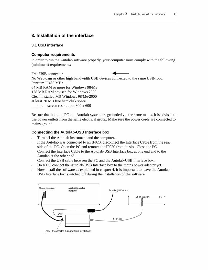
Connecting the Autolab-USB Interface box • Turn off the Autolab instrument and the computer. • If the Autolab was connected to an IF020, disconnect the Interface Cable from the rear
side of the PC. Open the PC and remove the IF020 from its slot. Close the PC. • Connect the Interface Cable to the Autolab-USB Interface box at one end and to the
Autolab at the other end. • Connect the USB cable between the PC and the Autolab-USB Interface box. • Do NOT connect the Autolab-USB Interface box to the mains power adapter yet. • Now install the software as explained in chapter 4. It is important to leave the Autolab-
USB Interface box switched off during the installation of the software.
USB Cable
PC USB Connectors
Autolab or µAutolab rear panel
Adapter
To mains (100-240 V ~)
5V DC
Leave disconnected during software installation !!
37-pole D-connector

12 Installation and Diagnostics Guide
Connecting the Autolab-USB (Internal) The Autolab-USB is an Autolab or a µAutolab system equipped with a direct USB connection at the rear side of the instrument. • Turn off the Autolab instrument and the computer. • Connect the USB cable between the PC and the Autolab-USB. • Do NOT switch on the Autolab-USB yet. • Now install the software as explained in chapter 4. It is important to leave the Autolab-
USB switched off during the installation of the software. Autolab-USB with PGSTAT12, PGSTAT30 or PGSTAT100: µAutolab-USB:
Autolab rear panel
USB Connectors PC
USB Connectors PC µAutolab rear panel
Chapter 3 Installation of the interface 13
3.2 ISA - IF020 interface
Computer requirements In order to run the Autolab software properly, your computer must comply with the following (minimum) requirements: a free ISA slot (120 x 175 mm: height x width) Pentium 120 MHz 32 MB RAM or more (for Windows 2000, 128 MB is advised) MS-Windows 95/98/Me/NT/2000 at least 20 MB free hard-disk space minimum screen resolution; 800 x 600 Be sure that both the PC and Autolab-system are grounded via the same mains. It is advised to use power outlets from the same electrical group. Make sure the power cords are connected to mains ground.
Inserting the interface board • Turn off the Autolab instrument and the computer. • Open the computer case, in order to expose its ISA slots. • In case you have an older Autolab interface card already installed (W3.11/DOS), please
remove it. • Put the interface board in a free ISA slot, and fasten the screw on the mounting frame.
Before handling the interface board, remove static electricity from your hand by touching the exposed computer frame.
• Close the computer case and connect the interface cable. The interface board is supplied with default factory settings. In most cases, these settings will not interfere with other devices. However, in case you experience problems, please follow the directions in the next paragraph after you have installed the Autolab software.
Configuring the interface board On the interface board two settings can be changed: the interface base address (SW101) and the Autolab grounding (JP201, JP202). Before changing any setting, the board must be removed from the computer. Never remove or insert the board when the computer is turned on.

14 Installation and Diagnostics Guide
By default, the base address is set to 280Hex, but it can be changed if this setting interferes with other devices, or when multiple Autolab interface boards are present in the same computer. The interface will occupy 8 addresses, starting from the base address. The base address can be set with SW101 by opening in the Control Panel the “Autolab Interface Board” applet (see next figure).
The Autolab interface board.
Set Base Address.

Chapter 3 Installation of the interface 15
In order to find an unoccupied address range, you should do the following: • In Windows 95/98 or Me, right-click My Computer, select Properties, go to Device
manager, double-click Computer (left top), select View resources and choose the Input/output radio button. You will see which addresses are used by which devices, and which addresses are still available.
• In Windows NT, start “Programs/Administrative Tools/Windows NT diagnostics”, select “resources” tab and press I/O Port.
• In Windows 2000, start “Settings/Control Panel/Administrative Tools/Computer Management”, select “System Information/Hardware Resources” and select “I/O”.
The procedure to change the base address: • Set the base address with the control panel applet “Autolab Interface Board” and write
down the dip switch settings. • Turn computer and Autolab off. • Take out the interface card and set the dip switches of SW101; d1-d8 according to the dip
switch settings from step 1. • Place the board back in the PC, close the case and start the PC. The jumpers on the interface board indicated as JP201 and JP202 will select the grounding mode of the Autolab instrument. The proper setting depends on the type of instrument. It is usually set by the manufacturer. In case of switching between instruments or in case a mix-up of interfaces occurs, you should verify its proper setting. Autolab type JP201 JP202 PGSTAT12/30/100 in new Autolab cabinet (from June 1999) ON ON µAutolab and µAutolab type II OFF ON PGSTAT10/20/30/100 from April 1994 in old Autolab cabinet ON OFF PSTAT10/PGSTAT10/20 to March 1994 OFF ON Please contact Eco Chemie to inquire about your specific case. In case the jumper setting is incorrect, it is possible the PC cannot communicate with the Autolab instrument. You will be notified with : “Cannot Read Autolab”

Chapter 4 Installing the software 17
4. Installing the software
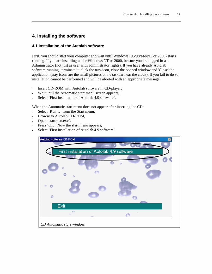
4.1 Installation of the Autolab software First, you should start your computer and wait until Windows (95/98/Me/NT or 2000) starts running. If you are installing under Windows NT or 2000, be sure you are logged in as Administrator (not just as user with administrator rights). If you have already Autolab software running, terminate it: click the tray-icon, close the opened window and 'Close' the application (tray-icons are the small pictures at the taskbar near the clock). If you fail to do so, installation cannot be performed and will be aborted with an appropriate message. • Insert CD-ROM with Autolab software in CD-player, • Wait until the Automatic start menu screen appears, • Select ‘First installation of Autolab 4.9 software’. When the Automatic start menu does not appear after inserting the CD: • Select ‘Run…’ from the Start menu, • Browse to Autolab CD-ROM, • Open ‘startmen.exe’, • Press ‘OK’. Now the start menu appears, • Select ‘First installation of Autolab 4.9 software’.
CD Automatic start window.
18 Installation and Diagnostics Guide
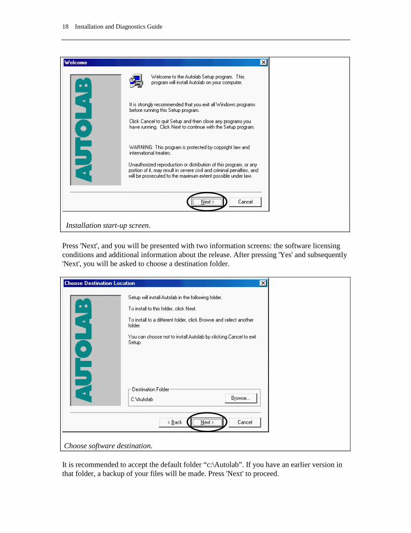
Installation start-up screen. Press 'Next', and you will be presented with two information screens: the software licensing conditions and additional information about the release. After pressing 'Yes' and subsequently 'Next', you will be asked to choose a destination folder.
Choose software destination. It is recommended to accept the default folder “c:\Autolab”. If you have an earlier version in that folder, a backup of your files will be made. Press 'Next' to proceed.

Chapter 4 Installing the software 19
Select software components. By default, the Gpes and Diagnostics programs are selected. When your instrument has a FRA or FRA2 module, you should also select the FRA checkbox. If your instrument is a multichannel instrument, with either two or more Array modules or two or more PGSTAT10 modules, you must select the Multichannel checkbox. Press 'Next' to proceed.
Select Autolab interface. Read this Window carefully. It defines the type of interface you are using. Normally you have to select one of the first two items (USB or ISA). After pressing 'Next', you will be asked to enter a program folder for the program shortcuts. It is recommended to accept the default: 'Autolab Programs' and proceed with 'Start Copying'.
20 Installation and Diagnostics Guide
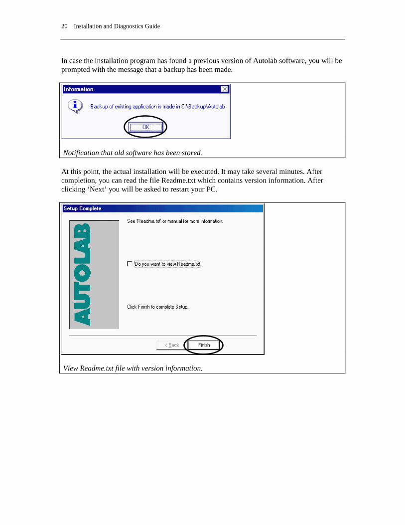
In case the installation program has found a previous version of Autolab software, you will be prompted with the message that a backup has been made.
Notification that old software has been stored. At this point, the actual installation will be executed. It may take several minutes. After completion, you can read the file Readme.txt which contains version information. After clicking ‘Next’ you will be asked to restart your PC.
View Readme.txt file with version information.
Chapter 4 Installing the software 21
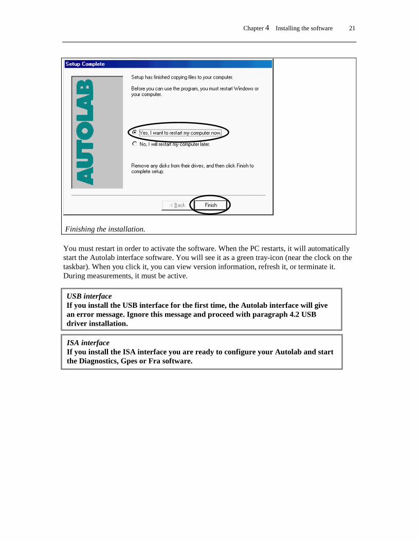
Finishing the installation. You must restart in order to activate the software. When the PC restarts, it will automatically start the Autolab interface software. You will see it as a green tray-icon (near the clock on the taskbar). When you click it, you can view version information, refresh it, or terminate it. During measurements, it must be active.
USB interface If you install the USB interface for the first time, the Autolab interface will give an error message. Ignore this message and proceed with paragraph 4.2 USB driver installation.
ISA interface If you install the ISA interface you are ready to configure your Autolab and start the Diagnostics, Gpes or Fra software.

22 Installation and Diagnostics Guide
4.2 USB driver installation (For Windows 98/Me/2000 systems only) • Before installation of the USB driver you first need to install the Autolab software as
described in paragraph 4.1. This installation must be done without the USB interface connected. After the first reboot of the computer the Autolab Interface software will fail, click OK to ignore this message.
• The USB driver only needs to be installed the first time the Autolab is connected via the
USB interface. • In the examples the folder name c:\Autolab is used. This folder name may be different if
the destination folder name was changed during the installation of the Autolab software (see paragraph 4.1)
• Do not cancel the installation. The Autolab may not operate correctly if the installation is incomplete.

Chapter 4 Installing the software 23
Installing the USB Driver for Windows 98 Your computer may ask you to insert the Windows installation CD. It is possible that the USB drivers are already installed on your system, but to be sure it is recommended that you have the original Windows CD available. 1. Connect the USB-cable to the Autolab-USB or to the Autolab-USB Interface box and PC.
Switch on the Autolab-USB or connect the power cable to the Autolab-USB Interface box.
The ‘Add New Hardware Wizard’ dialog will appear after a moment. If in this line ‘Unknown Device’ appears go to step 7.
2. Read the dialog and click the ‘Next’ button. 3. Select ‘Search for the best driver for your device (recommended)’ and click the ‘Next’
button.
24 Installation and Diagnostics Guide
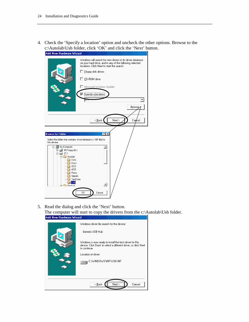
4. Check the ‘Specify a location’ option and uncheck the other options. Browse to the
c:\Autolab\Usb folder, click ‘OK’ and click the ‘Next’ button.
5. Read the dialog and click the ‘Next’ button. The computer will start to copy the drivers from the c:\Autolab\Usb folder.

Chapter 4 Installing the software 25
If the computer asks for the Windows CD during the installation and you do have this CD available:
• Insert the Windows CD into the CD player and press OK.
If the computer asks for the Windows CD during the installation and you do NOT have this CD available:
• Browse to the c:\Autolab\Usb folder in order to find the proper drivers.
WARNING: It is possible that the delivered driver with the Autolab is not the proper driver for the available Windows version. If you encounter any problem with communication between PC and Autolab, please install the USB drivers from the original Windows CD.
26 Installation and Diagnostics Guide
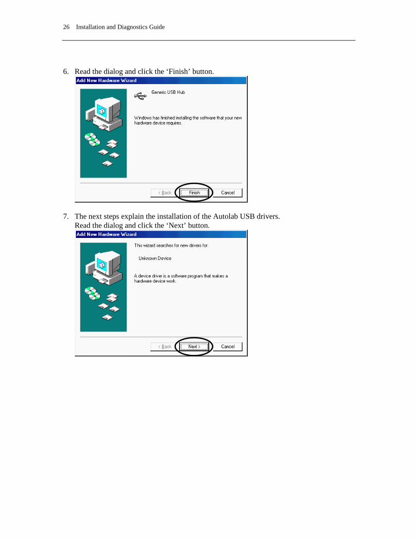
6. Read the dialog and click the ‘Finish’ button.
7. The next steps explain the installation of the Autolab USB drivers.
Read the dialog and click the ‘Next’ button.

Chapter 4 Installing the software 27
8. Select ‘Search for the best driver for your device (recommended) and click the ‘Next’
button.
9. Check the ‘Specify a location’ option and uncheck the other options. Browse to the c:\Autolab\Usb folder, click ‘OK’ and click the ‘Next’ button.

28 Installation and Diagnostics Guide
10. The computer will start to copy the drivers from the c:\Autolab\Usb folder.
Read the dialog and click the ‘Next’ button.
11. Read the dialog and click the ‘Finish’ button.
• You could be asked to restart your PC. Remove the CD-ROM from the drive and restart the computer. The Autolab Interface will start automatically and the system is ready to control the Autolab. You can start the Diagnostics, Gpes or Fra software. You can skip the next steps.
12. If it is not necessary to restart the computer remove the CD-ROM from the drive and
select the Autolab Interface icon in the system tray.

Chapter 4 Installing the software 29
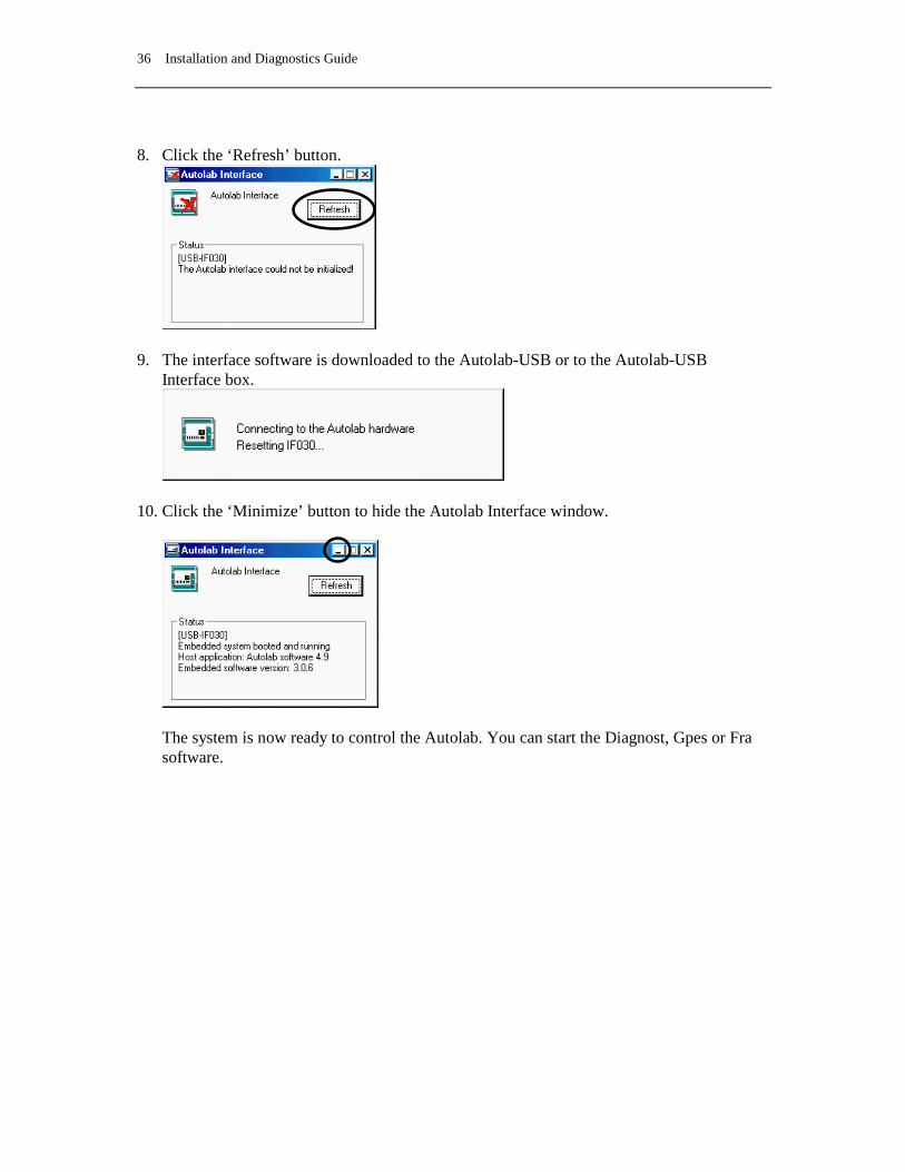
13. Click the ‘Refresh’ button.
14. The interface software is downloaded to the Autolab-USB or to the Autolab-USB
Interface box.
15. Click the ‘Minimize’ button to hide the Autolab Interface window.
The system is now ready to control the Autolab. You can start the Diagnostics, Gpes or Fra software.
30 Installation and Diagnostics Guide
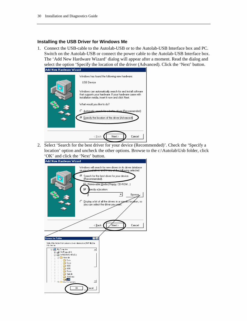
Installing the USB Driver for Windows Me 1. Connect the USB-cable to the Autolab-USB or to the Autolab-USB Interface box and PC.
Switch on the Autolab-USB or connect the power cable to the Autolab-USB Interface box. The ‘Add New Hardware Wizard’ dialog will appear after a moment. Read the dialog and select the option ‘Specify the location of the driver (Advanced). Click the ‘Next’ button.
2. Select ‘Search for the best driver for your device (Recommended)’. Check the ‘Specify a
location’ option and uncheck the other options. Browse to the c:\Autolab\Usb folder, click ‘OK’ and click the ‘Next’ button.
Chapter 4 Installing the software 31
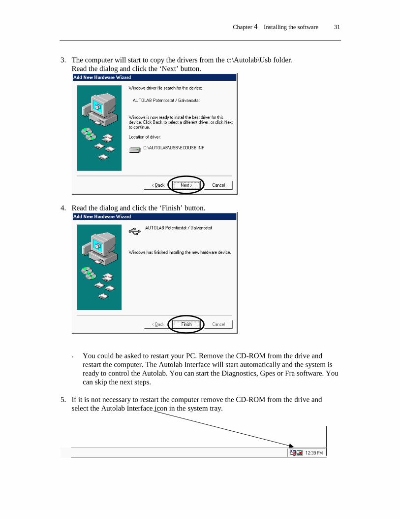
3. The computer will start to copy the drivers from the c:\Autolab\Usb folder. Read the dialog and click the ‘Next’ button.
4. Read the dialog and click the ‘Finish’ button.
• You could be asked to restart your PC. Remove the CD-ROM from the drive and
restart the computer. The Autolab Interface will start automatically and the system is ready to control the Autolab. You can start the Diagnostics, Gpes or Fra software. You can skip the next steps.
5. If it is not necessary to restart the computer remove the CD-ROM from the drive and
select the Autolab Interface icon in the system tray.

32 Installation and Diagnostics Guide
6. Click the ‘Refresh’ button.
7. The interface software is downloaded to the Autolab-USB or to the Autolab-USB Interface box.
8. Click the ‘Minimize’ button to hide the Autolab Interface window.
The system is now ready to control the Autolab. You can start the Diagnostics, Gpes or Fra software.

Chapter 4 Installing the software 33
Installing the USB Driver for Windows 2000 1. Connect the USB-cable to the Autolab-USB or to the Autolab-USB Interface box and PC.
Switch on the Autolab-USB or connect the power cable to the Autolab-USB Interface box. The ‘Found New Hardware Wizard’ dialog will appear after a moment. Click the ‘Next’ button.
2. Select ‘Search for a suitable driver for my device (recommended) and click the ‘Next’
button.

34 Installation and Diagnostics Guide
3. Read the dialog and select the option ‘Specify a location’. Click the ‘Next’ button.
4. Browse to the c:\Autolab\Usb folder, select the ‘EcoUsb’ driver and click ‘Open’. Click the ‘OK’ button.
Chapter 4 Installing the software 35
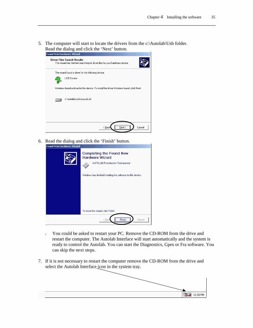
5. The computer will start to locate the drivers from the c:\Autolab\Usb folder.
Read the dialog and click the ‘Next’ button.
6. Read the dialog and click the ‘Finish’ button.
• You could be asked to restart your PC. Remove the CD-ROM from the drive and restart the computer. The Autolab Interface will start automatically and the system is ready to control the Autolab. You can start the Diagnostics, Gpes or Fra software. You can skip the next steps.
7. If it is not necessary to restart the computer remove the CD-ROM from the drive and
select the Autolab Interface icon in the system tray.
36 Installation and Diagnostics Guide
8. Click the ‘Refresh’ button.
9. The interface software is downloaded to the Autolab-USB or to the Autolab-USB Interface box.
10. Click the ‘Minimize’ button to hide the Autolab Interface window.
The system is now ready to control the Autolab. You can start the Diagnost, Gpes or Fra software.
Chapter 5 µAutolab Type II 37
5. µAutolab Type II
5.1 Front panel controls and connections On the front panel of the µAutolab type II you will find one connector, two push buttons and a number of LED indicators. The power on/off switch is situated on the left side and the manual cell enable switch is situated on the right side. This switch provides the option of disabling the internal cell switch, irrespective of its setting in the software. It is normally enabled (and then completely under software control) but you may turn it off by pressing the button. It can be enabled again by pressing the button once more. The main purpose of the cell enable switch is to provide a manual emergency 'cell disconnection' function. The LED indicators display the status of the µAutolab type II. Selected current range, cell on/off, High Stability or High Speed mode, potentiostat or galvanostat mode, and V and I overloads are shown. All indicators are shown in the Manual control window in the GPES software as well. The cell cable is connected to the µAutolab type II by means of the DIN connector on the front. This cable has four connectors: working or indicator electrode (red) reference electrode (blue) auxiliary or counter electrode (black) analog ground (green) The settings of the µAutolab type II on power-up are pre-defined. The cell connections is switched off, but the software is enabled to switch the cell connection 'on'. The 1mA current range is selected, in potentiostat mode and High Stability mode.
5.2 Noise Some precautions should be taken when measuring low level currents in order to minimise noise. The personal computer and screen must be placed as far away as possible from the electrochemical cell and the cell cable. The cell cable should not cross other electrical cables. Other equipment with power supplies can also cause noise. For instance, if present, the interface for mercury electrodes IME should also be placed with some care. If possible place the computer between the µAutolab type II and the printer. Prevent using unshielded extension cables to the electrodes. The use of a Faraday cage is also advised. If the cell system has a ground connector, the analog ground (green) of the µAutolab type II can be connected to it. If a Faraday cage is used, it should be connected to this ground connector. Some experiments concerning optimisation of the signal to noise ratio can readily indicate whether or not a configuration is satisfactory.

38 Installation and Diagnostics Guide
5.3 Rear panel connections for analog signals On the rear panel, there are four BNC connectors. All signals are with respect to µAutolab Ground and indirectly to Protective Earth. Avoid creating ground loops as this will often degrade the performance of the instrument as a whole. From left to right, the following signals are available: Iout (output) The voltage on this connector represents the measured current. A 1V
signal corresponds to 1* the selected current range. The output level varies between ±10V. The output impedance is 50Ω, so a correction should be made if a load <100kΩ is connected. Minimum load impedance is 200Ω.
Eout (output) This is the potential of RE versus WE. The output impedance is 50Ω, so a correction should be made if a load <100kΩ is connected. The output voltage will vary between ±10V.
Vout (output) This output is controlled by software and is meant to be used to control the rotating speed of a Rotating Disc Electrode. The output level varies between ±10V and the output impedance is very low, <1Ω. The output amplifier is capable of providing 5mA at full scale, so load impedance should be >2kΩ.
Vin (input) This is an analog input that can be used for measuring a second signal (see paragraph 12.2).
5.4 High Speed and High Stability The µAutolab is equipped with a High Speed mode and a High Stability (HStab) mode. The purpose of these different modes of operation is to provide maximum bandwidth, maintaining stability in the potentiostat or galvanostat control loop. The normal mode of operation is High Stability. This gives the Control Amplifier a bandwidth of 12.5 kHz or somewhat less when high gains (low current ranges) are demanded. The High Stability indicator on the front panel of the µAutolab will light up to show that High Stability mode is active. This setting is the most appropriate for performing measurements at low sampling rates. The noise in the I and E signals will be minimised. However, for higher sampling rates you will need to use a faster mode of operation, i.e. the High Speed mode. The Control Amplifier will have its bandwidth extended to 500 kHz. Again, a higher gain demand will slightly lower the cut-off frequency. Some cells can show ringing or oscillation using High Speed, particularly highly capacitive cells in potentiostat mode. There will be an increase in noise levels for E and/or I, when High Speed is used.
5.5 RE input impedance and stability The electrometer RE input, contains a small capacitive load. If the capacitive part of the impedance between CE and RE is comparatively large, phase shift will occur which can lead to stability problems when working in potentiostat mode. If the system oscillates and the impedance between RE and CE is fixed, then you have to select the ‘High Stability mode’ to

Chapter 5 µAutolab Type II 39
enlarge the system stability. In general, the use of High Stability will lead to a more stable control loop, this means also that the systems bandwidth will decrease. In galvanostat mode this large impedance between CE and RE, will usually not lead to stability problems, because of the current feedback regulation (constant current).
5.6 Maximum reference electrode voltage Special care should be taken in cases where the impedance between RE and CE is relatively small compared to the cell impedance between RE and WE (full drop of the applied voltage). The possibility appears that the potential difference between RE and WE will exceeds the approximately 10V. The electrometer RE input contains an input protection circuitry and becomes active after crossing this 10V limit. This is implemented to avoid electrometer damage. Please note that the Vovl indicator will not light up for this type of voltage overload. In High Speed mode, oscillation may occur when exceeding this maximum reference (electrode) voltage limit. It is recommended to use the High Stability mode for these kind of cells. In galvanostat mode, similar difficulties may arise, although galvanostat loop stability is not affected. When crossing the common mode voltage limit (±10V) the measured cell voltage will not represent the actual cell voltage but will show a large value (10.00V). Here too, the Vovl indicator will not light up. There is no specific need to select the High Stability mode.
5.7 Active cells Some electrochemical cells such as batteries and fuel cells are capable of delivering power to the µAutolab type II. This is allowed only to a maximum ‘cell’ power of 0.5W. This means that cells which show a voltage of less than 0.5V between WE and CE are intrinsically safe. They may drive the µAutolab's output stage into current limit but will not overload the amplifier. On the other hand, cells that have a higher voltage may only deliver a current of; 0.5W divided by the cell voltage.
5.8 Grounded cells The measurement circuit of µAutolab type II is internally connected to Protective Earth (P.E.). This can be an obstacle when measurement is desired of a cell that is itself in contact with P.E. In such a case undefined currents will flow through the loop that is formed when the electrode connections from the µAutolab are linked to the cell. Measurement will not be possible. Please note that not only a short circuit or a resistance can make a connection to earth, but also a capacitance is capable of providing a conductive path (for AC signals). The earth connection between the cell and P.E. should always be broken. If there is no possibility to do this, please contact Eco Chemie to see if a custom solution can be found.

40 Installation and Diagnostics Guide
5.9 Environmental conditions The µAutolab may be used at ambient temperatures of 0 to 40 degrees Celsius. The instrument is calibrated at 25 degrees Celsius and will show minimum errors at that temperature. Never place the instrument in direct sunlight or close to any heating source.
5.10 Cleaning and inspection It is recommended to clean the µAutolab cabinet and the accessories on a regular basis. This can be done with a damp cloth, optionally using a mild detergent. Never use an excessive amount of water; it may never enter into the instrument. As a precaution, disconnect µAutolab from the mains when cleaning it. Also perform an inspection of the instrument and of all of the connecting cables. If you find any cable with damaged insulation or other irregularities like badly corroded banana connectors, stop using the instrument until it has been repaired. Damaged equipment or damaged cables may be hazardous!

Chapter 6 Autolab with PGSTAT10 41
6. Autolab with PGSTAT10
6.1 Front panel controls and connections On the front panel of the PGSTAT10 you will find one connector, two push buttons and a number of LED indicators. The power on/off switch is situated on the left side and the manual cell enable switch above the cell connector. This switch provides the option of disabling the internal cell switch, irrespective of its setting in the software. It is normally enabled (and then completely under software control) but you may turn it off by pressing the button. It can be enabled again by pressing the button once more. The main purpose of the cell enable switch is to provide a manual emergency 'cell disconnection' function. The LED indicators display the status of the PGSTAT10. Selected current range, cell on/off, High Stability or High Speed mode, potentiostat or galvanostat mode, and V and I overloads are shown. All indicators are shown in the Manual control window in the GPES software as well. The cell cable is connected to the PGSTAT10 by means of the DIN connector on the front. This cable has four connectors: working or indicator electrode (red) reference electrode (blue) auxiliary or counter electrode (black) analog ground (green) The settings of the PGSTAT10 on power-up are pre-defined. The cell connection is switched off, but the software is enabled to switch the cell connection 'on'. The 1mA current range is selected, in potentiostat mode and High Stability mode.
6.2 Noise Some precautions should be taken when measuring low level currents in order to minimise noise. The personal computer and screen must be placed as far away as possible from the electrochemical cell and the cell cable. The cell cable should not cross other electrical cables. Other equipment with power supplies can also cause noise. For instance, if present, the interface for mercury electrodes IME should also be placed with some care. If possible place the computer between the PGSTAT10 and the printer. Prevent using unshielded extension cables to the electrodes. The use of a Faraday cage is also advised. If the cell system has a ground connector, the analog ground (green) of the PGSTAT10 can be connected to it. If a Faraday cage is used, it should be connected to this ground connector. Some experiments concerning optimisation of the signal to noise ratio can readily indicate whether or not a configuration is satisfactory.
42 Installation and Diagnostics Guide
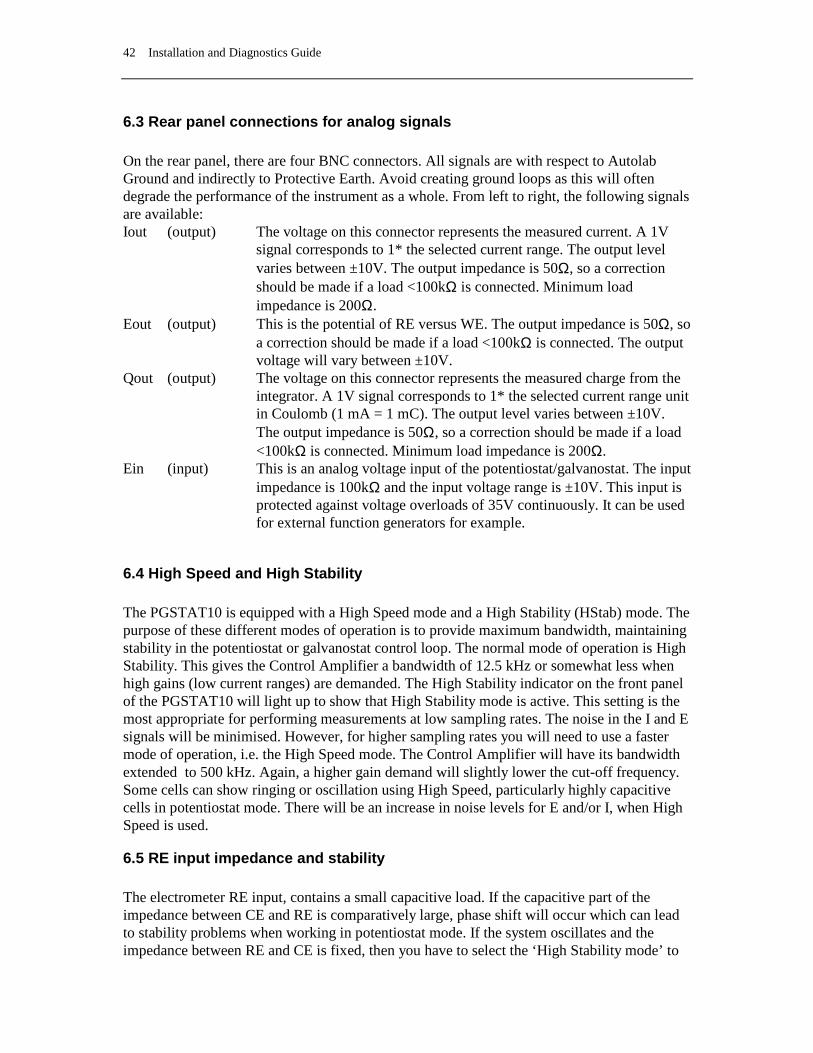
6.3 Rear panel connections for analog signals On the rear panel, there are four BNC connectors. All signals are with respect to Autolab Ground and indirectly to Protective Earth. Avoid creating ground loops as this will often degrade the performance of the instrument as a whole. From left to right, the following signals are available: Iout (output) The voltage on this connector represents the measured current. A 1V
signal corresponds to 1* the selected current range. The output level varies between ±10V. The output impedance is 50Ω, so a correction should be made if a load <100kΩ is connected. Minimum load impedance is 200Ω.
Eout (output) This is the potential of RE versus WE. The output impedance is 50Ω, so a correction should be made if a load <100kΩ is connected. The output voltage will vary between ±10V.
Qout (output) The voltage on this connector represents the measured charge from the integrator. A 1V signal corresponds to 1* the selected current range unit in Coulomb (1 mA = 1 mC). The output level varies between ±10V. The output impedance is 50Ω, so a correction should be made if a load <100kΩ is connected. Minimum load impedance is 200Ω.
Ein (input) This is an analog voltage input of the potentiostat/galvanostat. The input impedance is 100kΩ and the input voltage range is ±10V. This input is protected against voltage overloads of 35V continuously. It can be used for external function generators for example.
6.4 High Speed and High Stability The PGSTAT10 is equipped with a High Speed mode and a High Stability (HStab) mode. The purpose of these different modes of operation is to provide maximum bandwidth, maintaining stability in the potentiostat or galvanostat control loop. The normal mode of operation is High Stability. This gives the Control Amplifier a bandwidth of 12.5 kHz or somewhat less when high gains (low current ranges) are demanded. The High Stability indicator on the front panel of the PGSTAT10 will light up to show that High Stability mode is active. This setting is the most appropriate for performing measurements at low sampling rates. The noise in the I and E signals will be minimised. However, for higher sampling rates you will need to use a faster mode of operation, i.e. the High Speed mode. The Control Amplifier will have its bandwidth extended to 500 kHz. Again, a higher gain demand will slightly lower the cut-off frequency. Some cells can show ringing or oscillation using High Speed, particularly highly capacitive cells in potentiostat mode. There will be an increase in noise levels for E and/or I, when High Speed is used.
6.5 RE input impedance and stability The electrometer RE input, contains a small capacitive load. If the capacitive part of the impedance between CE and RE is comparatively large, phase shift will occur which can lead to stability problems when working in potentiostat mode. If the system oscillates and the impedance between RE and CE is fixed, then you have to select the ‘High Stability mode’ to

Chapter 6 Autolab with PGSTAT10 43
enlarge the system stability. In general, the use of High Stability will lead to a more stable control loop, this means also that the systems bandwidth will decrease. In galvanostat mode this large impedance between CE and RE, will usually not lead to stability problems, because of the current feedback regulation (constant current).
6.6 Maximum reference electrode voltage Special care should be taken in cases where the impedance between RE and CE is relatively small compared to the cell impedance between RE and WE (full drop of the applied voltage). The possibility appears that the potential difference between RE and WE will exceeds the approximately 10V. The electrometer RE input contains an input protection circuitry and becomes active after crossing this 10V limit. This is implemented to avoid electrometer damage. Please note that the Vovl indicator will not light up for this type of voltage overload. In High Speed mode, oscillation may occur when exceeding this maximum reference (electrode) voltage limit. It is recommended to use the High Stability mode for these kind of cells. In galvanostat mode, similar difficulties may arise, although galvanostat loop stability is not affected. When crossing the common mode voltage limit (±10V) the measured cell voltage will not represent the actual cell voltage but will show a large value (10.00V). Here too, the Vovl indicator will not light up. There is no specific need to select the High Stability mode.
6.7 Active cells Some electrochemical cells such as batteries and fuel cells are capable of delivering power to the PGSTAT10. This is allowed only to a maximum ‘cell’ power of 0.5W. This means that cells which show a voltage of less than 0.5V between WE and CE are intrinsically safe. They may drive the PGSTAT10’s output stage into current limit but will not overload the amplifier. On the other hand, cells that have a higher voltage may only deliver a current of; 0.5W divided by the cell voltage.
6.8 Grounded cells The measurement circuit of the PGSTAT10 is internally connected to Protective Earth (P.E.). This can be an obstacle when measurement is desired of a cell that is itself in contact with P.E. In such a case undefined currents will flow through the loop that is formed when the electrode connections from the PGSTAT10 are linked to the cell. Measurement will not be possible. Please note that not only a short circuit or a resistance can make a connection to earth, but also a capacitance is capable of providing a conductive path (for AC signals). The earth connection between the cell and P.E. should always be broken. If there is no possibility to do this, please contact Eco Chemie to see if a custom solution can be found.

44 Installation and Diagnostics Guide
6.9 Environmental conditions The Autolab with PGSTAT10 may be used at ambient temperatures of 0 to 40 degrees Celsius. The instrument is calibrated at 25 degrees Celsius and will show minimum errors at that temperature. Never place the instrument in direct sunlight or close to any heating source.
6.10 Front panel controls On the front panel, you will find a digital voltmeter (DVM) that either displays the measured potential, the measured current or the measured charge. You can toggle between the three by pressing the DVM switch, situated besides the DVM and indicated with E / I / Q. The potential will always be displayed in Volts, the current will be displayed in A, mA, µA or nA and the charge in C, mC, µC or nC, depending on the current range.
6.11 Cleaning and inspection It is recommended to clean the Autolab cabinet and the accessories on a regular basis. This can be done with a damp cloth, optionally using a mild detergent. Never use an excessive amount of water; it may never enter into the instrument. As a precaution, disconnect Autolab from the mains when cleaning it. Also perform an inspection of the instrument and of all of the connecting cables. If you find any cable with damaged insulation or other irregularities like badly corroded banana connectors, stop using the instrument until it has been repaired. Damaged equipment or damaged cables may be hazardous!

Chapter 7 Autolab with PGSTAT12 45
7. Autolab with PGSTAT12
7.1 Front panel and cell cable connections There are four connectors on the front panel of PGSTAT12. The cable that connects to the WE and CE electrodes should be plugged into the WE/CE socket while the cable with the cell pod (leading to the RE, S and optionally WE2 electrodes) connects to the RE/S socket. An earth connection (for shielding purposes, e.g. a Faraday cage) can be made with a standard 4 mm banana plug to the earth bulkhead. Finally a monitor cable can be connected to the socket. This monitor cable provides the Eout, Iout and Ein connections (see next paragraph). The cell cables should be connected as follows: working or indicator electrode WE (red) sense electrode S (red) reference electrode RE (blue) auxiliary or counter electrode CE (black) In a three electrode set-up the working electrode and sense lead are both connected to the working electrode. In a two electrode set-up the counter and reference electrode lead are both connected to the same electrode. The settings of the Autolab with PGSTAT12 on power-up are pre-defined. The cell is switched off and the current range 10mA is selected.
7.2 Noise When measuring low level currents some precautions should be taken in order to minimise noise. The personal computer must be placed as far away as possible from the electrochemical cell and the cell cable. The cell cable should not cross other electrical cables. Other equipment with power supplies can also cause noise. For instance, the interface for mercury electrodes IME should also be placed with some care. If possible place the computer between the Autolab with PGSTAT12 and the printer. Prevent using unshielded extension cables to the electrodes. The use of a Faraday cage is also advised. If the cell system has a ground connector, it can be connected to the analog ground connector at the front of the PGSTAT12. If a Faraday cage is used, it should be connected to this ground connector. Some experiments concerning optimisation of the signal to noise ratio can readily indicate whether or not a configuration is satisfactory (see Noise consideration chapter).

46 Installation and Diagnostics Guide
7.3 Connections for analog signals With the supplied monitor cable, there are a number of BNC connectors to the PGSTAT12 analog circuits. All the signals are with respect to Autolab Ground and indirectly to Protective Earth. Avoid creating ground loops as this will often degrade the performance of the PGSTAT12 as a whole. From top to bottom, the following signals are available: E OUT (output) This is the differential potential of S versus RE. The output impedance is 50Ω, so a correction should be made if a load <100kΩ is connected. Minimum load impedance is 200Ω. The output voltage will vary between ±10V. I OUT (output) This voltage represents the measured current. A 1V signal corresponds to 1*the selected current range. The output level varies between ±3.5V. The output impedance is 50Ω, so a correction should be made if a load <100kΩ is connected. Minimum load impedance is 200Ω. E IN (input) This is an analog voltage input, that can only be used after it has been enabled in software. Do not leave it enabled unnecessarily, to prevent noise entering the system. In PSTAT mode, a 1V signal will add 1V to the cell voltage, while in GSTAT mode a 1V signal causes an extra current of 1*the selected current range to flow. In both cases, the external signal adds to any pre-set voltage or current. The input voltage range is ±10V, although a voltage or current overload situation may occur at lower voltage levels. Input impedance is 1kΩ (only when input is activated) so a correction should be made for source impedance’s > 1Ω. To enable this input change record 75, 3 of the SYSDEF40.INP file into 0 in stead of 1 (see paragraph 15.2)
7.4 High Speed and High Stability The PGSTAT12 is equipped with a High Speed mode and a High Stability (HStab) mode. The purpose of these different modes of operation is to provide a maximum bandwidth, maintaining stability in the PSTAT or GSTAT control loop. The normal mode of operation is High Stability. This gives the Control Amplifier a bandwidth of 12.5 kHz or somewhat less when high gains are demanded. The HStab indicator on the front panel of the PGSTAT12 will light up to show that High Stability mode is active. This setting is the most appropriate for performing measurements at low frequencies. The noise in the I and E signals will be minimised. However, for higher frequencies you will need to use a faster mode of operation. The other option is to use the High Speed mode. The Control Amplifier will have its bandwidth extended with one decade up to 125 kHz. Again, a higher gain demand will slightly lower the cut-off frequency. Some cells can show ringing or oscillation using High

Chapter 7 Autolab with PGSTAT12 47
Speed. Particularly highly capacitive cells in PSTAT mode. There will an increase in noise levels for E and/or I, when High Speed mode is used. For applications requiring very high bandwidth, there is the Ultra High Speed mode. This mode is reserved for performing FRA measurements at frequencies >100 kHz. There is a serious oscillation risk here, as the Control Amplifier bandwidth is extended yet to 500 kHz. Noise levels will generally show an increase once again. The Ultra High Speed mode is used by the FRA-software only. There is no possibility for the user to switch this mode on or off. The higher the bandwidth of operation, the more important it is to pay attention to adequate shielding of the cell and the electrode connectors. Please use a Faraday cage.
7.5 RE input impedance and stability The electrometer RE input contains a small capacitive load. If the capacitive part of the impedance between CE and RE is comparatively large, phase shift will occur which can lead to stability problems when working in potentiostat mode. If the system oscillates and the impedance between RE and CE is fixed, then you have to select the ‘High Stability mode’ to enlarge the system stability. In general, the use of High Stability will lead to a more stable control loop, this means also that the systems bandwidth will decrease. To make use of the full potentiostat bandwidth (ultra high speed mode), the impedance between CE & RE has to be lower than 35kΩ. This value is derived by testing. In galvanostat mode this large impedance between CE and RE, will usually not lead to stability problems, because of the current feedback regulation (constant current).
7.6 Galvanostatic FRA measurements The above mentioned (capacitive part of the impedance between RE to ground) is an important aspect to consider when performing FRA measurements in galvanostat mode. A large reference electrode impedance may create a phase shift which can appear at a lower frequency then a phase shift caused by the cell. The origin of the (error) phase shift between the Counter electrode and the Reference electrode can not be determined from the FRA data. Galvanostatic FRA measurements at 1 MHz require a maximum of 3kΩ reference electrode to keep phase errors within the ±5º.

48 Installation and Diagnostics Guide
7.7 Galvanostat and iR-compensation bandwidth For galvanostatic measurements on low current ranges, the bandwidth of the system is limited more by the current measurement circuitry than it is by the Control Amplifier. In fact, for reasons of stability, the Ultra High Speed and High Speed modes are disabled automatically for current ranges 1 µA and lower. The Ultra High Speed mode is also disabled for the 10 µA and 100 µA current ranges. As the current measurement circuit plays an important role in the iR compensation technique, its use is also subject to bandwidth limitations. A general indication of the maximum available bandwidth for GSTAT and for iR compensation is as follows: Galvanostat iR-comp/Potentiostat ranges 1 A-1 mA: 500 kHz 500 kHz range 100 µA : 125 kHz 500 kHz range 10 µA: 100 kHz 100 kHz range 1 µA: 10 kHz 10 kHz range 100 nA: 1 kHz 1 kHz range 10 nA: 100 Hz 100 Hz At the same time the iR-compensation bandwidth limits indicate up to which frequency current measurements can be made in potentiostat mode (either with or without iR-compensation). Please note that the bandwidths stated above apply to the Ultra High Speed mode (only available in FRA software). When using the High Speed mode these bandwidths are limited to a maximum value of 125 kHz, in High Stability mode they are limited to 12.5 kHz.
7.8 Oscillation detection The PGSTAT12 has a detector for large-amplitude oscillation. The detector will spot any signal swing that causes the control amplifier to produce both a positive and a negative Voltage Overload within approx. 200 µs. Thus, large oscillations at frequencies >2.5 kHz will be detected. Upon oscillation, the Vovl and Osc indicators on the PGSTAT12 front panel will light up. If enabled in software, the occurrence of oscillation will also immediately turn off the manual cell switch. To indicate that this was done by the oscillation detector, the Osc indicator will blink, as well as the manual cell switch sometimes. The PGSTAT12 output may be turned on again by pressing the manual cell switch button. If oscillation commences again, the cell switch will be turned off as soon as the button is released. Holding the button pressed in, provides an opportunity to observe the system during oscillation. Some cells that cause ringing when switching the cell on or changing the current range can falsely trigger the oscillation detector.

Chapter 7 Autolab with PGSTAT12 49
7.9 Maximum reference electrode voltage Special care should be taken in cases where the impedance between RE and CE is relatively small compared to the cell impedance between RE and WE (full drop of the applied voltage). The possibility appears that the potential difference between RE and WE will exceeds the approximately 10V. The electrometer RE input contains an input protection circuitry and becomes active after crossing this 10V limit. This is implemented to avoid electrometer damage. Please note that the Vovl indicator will not light up for this type of voltage overload. In High Speed mode, oscillation may occur when exceeding this maximum reference (electrode) voltage limit. It is recommended to use the High Stability mode for these kind of cells. In galvanostat mode, similar difficulties may arise, although galvanostat loop stability is not affected. When crossing the common mode voltage limit (±10V) the measured cell voltage will not represent the actual cell voltage but will show a large value (10.00V). Here too, the Vovl indicator will not light up. There is no specific need to select the High Stability mode.
7.10 Active cells Some electrochemical cells such as batteries and fuel cells are capable of delivering power to the PGSTAT12. This is allowed only to a maximum ‘cell’ power of 2.5W. This means that cells which show a voltage of less than 10V between WE and CE are intrinsically safe. They may drive the PGSTAT12 output stage into current limit but will not overload the amplifier. On the other hand, cells that have a higher voltage may only deliver a current of; 2.5W divided by the cell voltage.
7.11 Grounded cells The measurement circuitry of Autolab is internally connected to Protective Earth (P.E.). This can be an obstacle when measurement is desired of a cell that is itself in contact with P.E. In such a case, undefined currents will flow through the loop that is formed when the electrode connections from the PGSTAT are linked to the cell and measurement will not be possible. Please note that not only a short circuit or a resistance can make a connection to earth, but that also a capacitance is capable of providing a conductive path (for AC signals). The earth connection between the cell and P.E. should always be broken. If there is no possibility of doing this, please contact Eco Chemie to see if a custom solution to your problem can be found.
7.12 Environmental conditions The Autolab with PGSTAT12 may be used at temperatures of 0 to 40 degrees Celsius. The instrument is calibrated at 25 degrees Celsius and will show minimum errors at that temperature. The ventilation holes in the bottom and rear panels may never be obstructed, nor should the instrument be placed in intense sunlight or near an other source of heat.

50 Installation and Diagnostics Guide
7.13 Temperature overload As a safety precaution, the PGSTAT12 is equipped with a circuit that monitors the temperature of the internal power electronics. A temperature overload will be displayed as a blinking indicator in the manual cell switch, with the cell automatically turned off. You will not be able to turn the cell back on until the temperature inside the instrument has fallen to an acceptable level. It can then be switched on again by pressing the manual cell switch button on the front panel. During normal operation the temperature should never become extremely high and no temperature overload will occur. If it does, take time to find out what caused it to happen. Is the room temperature extremely high? Was the PGSTAT12 oscillating? Is the voltage selector for mains power set to the right value? Is the fan turning and are all the ventilation holes open? Was the cell delivering a considerable amount of power to the PGSTAT12? Are the WE and CE cables shorted in PSTAT mode (they should not be!)? If a temperature overload takes place repeatedly for no obvious reason, Eco Chemie recommends to have the instrument checked by their service department.
7.14 Front panel controls On the black front panel, you will find a digital voltmeter (DVM) that either displays the measured potential or the measured current. You can toggle between the two by pressing the DVM switch, situated below the DVM in the black panel and indicated with E / I. The potential will always be displayed in Volts, the current will be displayed in A, mA, µA or nA, depending on the current range. The manual cell on/off switch is situated in the blue edge at the right. This switch provides the option of disabling the internal cell switch, irrespective of its setting in software. It is normally enabled, but you may turn it off by pressing the button. The indicator in the switch will be off. This situation can be reversed by pressing the button again. If the indicator in the switch is on, the cell switch is enabled and is completely under software control.
7.15 ECD measurements If your Autolab is equipped with an ECD module, it is possible to perform measurements at extremely low currents. In combination with the PGSTAT12 this can be done very easily. Because of the slow response and optional filtering action of the ECD current measurement circuitry, galvanostatic operation is not available. Although the current is no longer measured in the PGSTAT12 but in the separate ECD module, you can simply use the PGSTAT12 cell cable. Using the ECD module, you can implement current ranges 100 µA to 100 pA. When activated in software, the black front panel will show “*0.001” below the selected current range, indicating that the actual current range is 3 decades lower than what is shown on the front panel. The DVM will not display the ECD current and it will be fixed on displaying potential. In other words: The DVM switch is disabled.

Chapter 7 Autolab with PGSTAT12 51
7.16 Cleaning and inspection It is recommended to clean the Autolab cabinet and the accessories on a regular basis. This can be done with a damp cloth, optionally using a mild detergent. Never use an excessive amount of water; it may never enter into the instrument. As a precaution, disconnect Autolab from the mains when cleaning it. Also perform an inspection of the instrument and of all of the connecting cables. If you find any cable with damaged insulation or other irregularities, stop using the instrument until it has been repaired. Damaged equipment or damaged cables may be hazardous!


Chapter 8 Autolab with PGSTAT30 53
8. Autolab with PGSTAT30
8.1 Front panel and cell cable connections There are four connectors on the front panel of PGSTAT30. The cable that connects to the WE and CE electrodes should be plugged into the WE/CE socket while the cable with the cell pod (leading to the RE, S and optionally WE2 electrodes) connects to the RE/S socket. An earth connection (for shielding purposes, e.g. a Faraday cage) can be made with a standard 4 mm banana plug to the earth bulkhead. Finally a monitor cable can be connected to the socket. This monitor cable provides the Eout, Iout and Ein connections (see next paragraph). The cell cables should be connected as follows: working or indicator electrode WE (red) sense electrode S (red) reference electrode RE (blue) auxiliary or counter electrode CE (black) In a three electrode set-up the working electrode and sense lead are both connected to the working electrode. In a two electrode set-up the counter and reference electrode lead are both connected to the same electrode. The settings of the Autolab with PGSTAT30 on power-up are pre-defined. The cell is switched off and the current range 10mA is selected.
8.2 Noise When measuring low level currents some precautions should be taken in order to minimise noise. The personal computer must be placed as far away as possible from the electrochemical cell and the cell cable. The cell cable should not cross other electrical cables. Other equipment with power supplies can also cause noise. For instance, the interface for mercury electrodes IME should also be placed with some care. If possible place the computer between the Autolab with PGSTAT30 and the printer. Prevent using unshielded extension cables to the electrodes. The use of a Faraday cage is also advised. If the cell system has a ground connector, it can be connected to the analog ground connector at the front of the PGSTAT30. If a Faraday cage is used, it should be connected to this ground connector. Some experiments concerning optimisation of the signal to noise ratio can readily indicate whether or not a configuration is satisfactory (see Noise consideration chapter).
8.3 Connections for analog signals
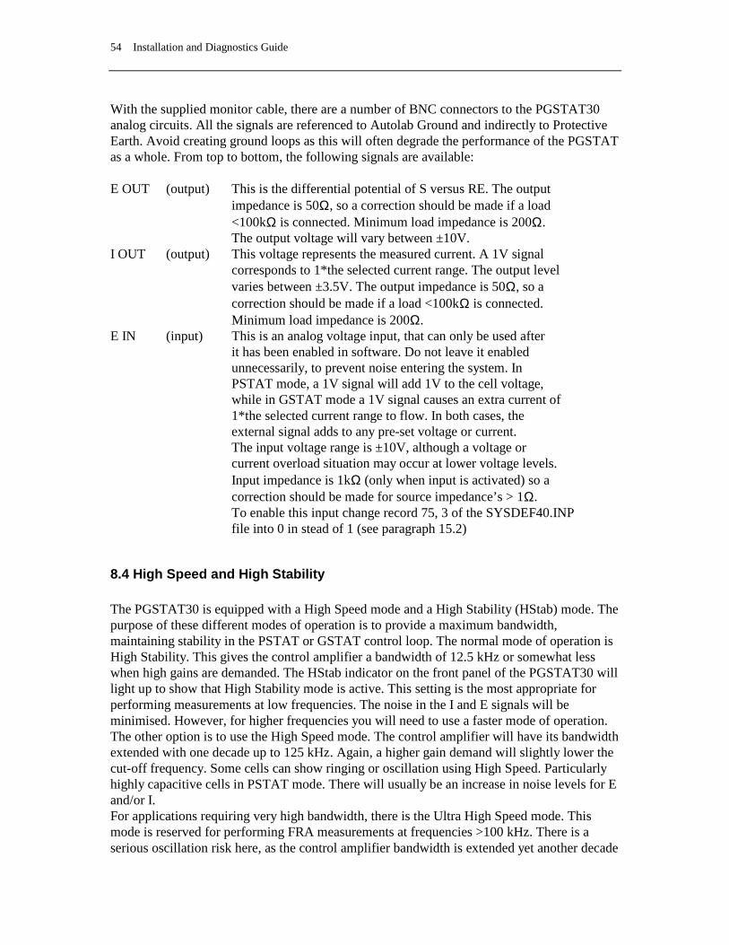
54 Installation and Diagnostics Guide
With the supplied monitor cable, there are a number of BNC connectors to the PGSTAT30 analog circuits. All the signals are referenced to Autolab Ground and indirectly to Protective Earth. Avoid creating ground loops as this will often degrade the performance of the PGSTAT as a whole. From top to bottom, the following signals are available: E OUT (output) This is the differential potential of S versus RE. The output impedance is 50Ω, so a correction should be made if a load <100kΩ is connected. Minimum load impedance is 200Ω. The output voltage will vary between ±10V. I OUT (output) This voltage represents the measured current. A 1V signal corresponds to 1*the selected current range. The output level varies between ±3.5V. The output impedance is 50Ω, so a correction should be made if a load <100kΩ is connected. Minimum load impedance is 200Ω. E IN (input) This is an analog voltage input, that can only be used after it has been enabled in software. Do not leave it enabled unnecessarily, to prevent noise entering the system. In PSTAT mode, a 1V signal will add 1V to the cell voltage, while in GSTAT mode a 1V signal causes an extra current of 1*the selected current range to flow. In both cases, the external signal adds to any pre-set voltage or current. The input voltage range is ±10V, although a voltage or current overload situation may occur at lower voltage levels. Input impedance is 1kΩ (only when input is activated) so a correction should be made for source impedance’s > 1Ω. To enable this input change record 75, 3 of the SYSDEF40.INP file into 0 in stead of 1 (see paragraph 15.2)
8.4 High Speed and High Stability The PGSTAT30 is equipped with a High Speed mode and a High Stability (HStab) mode. The purpose of these different modes of operation is to provide a maximum bandwidth, maintaining stability in the PSTAT or GSTAT control loop. The normal mode of operation is High Stability. This gives the control amplifier a bandwidth of 12.5 kHz or somewhat less when high gains are demanded. The HStab indicator on the front panel of the PGSTAT30 will light up to show that High Stability mode is active. This setting is the most appropriate for performing measurements at low frequencies. The noise in the I and E signals will be minimised. However, for higher frequencies you will need to use a faster mode of operation. The other option is to use the High Speed mode. The control amplifier will have its bandwidth extended with one decade up to 125 kHz. Again, a higher gain demand will slightly lower the cut-off frequency. Some cells can show ringing or oscillation using High Speed. Particularly highly capacitive cells in PSTAT mode. There will usually be an increase in noise levels for E and/or I. For applications requiring very high bandwidth, there is the Ultra High Speed mode. This mode is reserved for performing FRA measurements at frequencies >100 kHz. There is a serious oscillation risk here, as the control amplifier bandwidth is extended yet another decade

Chapter 8 Autolab with PGSTAT30 55
to >1.25 MHz. Noise levels will generally show an increase once again. The Ultra High Speed mode can only be used by the FRA-software. The user cannot switch it on or off from a Manual control window in the software. The higher the bandwidth of operation, the more important it is to pay attention to adequate shielding of the cell and the electrode connectors. Please use a Faraday cage.
8.5 RE input impedance and stability The electrometer RE input contains a small capacitive load. If the capacitive part of the impedance between CE and RE is comparatively large, phase shift will occur which can lead to stability problems when working in potentiostat mode. If the system oscillates and the impedance between RE and CE is fixed, then you have to select the ‘High Stability mode’ to enlarge the system stability. In general, the use of High Stability will lead to a more stable control loop, this means also that the systems bandwidth will decrease. To make use of the full potentiostat bandwidth (ultra high speed mode), the impedance between CE & RE has to be lower than 35kΩ. This value is derived by testing. In galvanostat mode this large impedance between CE and RE, will usually not lead to stability problems, because of the current feedback regulation (constant current).
8.6 Galvanostatic FRA measurements The above mentioned (capacitive part of the impedance between RE to ground) is an important aspect to consider when performing FRA measurements in galvanostat mode. A large reference electrode impedance may create a phase shift which can appear at a lower frequency then a phase shift caused by the cell. The origin of the (error) phase shift between the Counter electrode and the Reference electrode can not be determined from the FRA data. Galvanostatic FRA measurements at 1 MHz require a maximum of 3kΩ reference electrode to keep phase errors within the ±5º.

56 Installation and Diagnostics Guide
8.7 Galvanostat and iR-compensation bandwidth For galvanostatic measurements on low current ranges, the bandwidth of the system is limited more by the current measurement circuitry than it is by the control amplifier. In fact, for reasons of stability, the Ultra High Speed and High Speed modes are disabled automatically for current ranges 1 µA and lower. The Ultra High Speed mode is also disabled for the 10 µA and 100 µA current ranges. As the current measurement circuit plays an important role in the iR compensation technique, its use is also subject to bandwidth limitations. A general indication of the maximum available bandwidth for GSTAT and for iR compensation is as follows: Galvanostat iR-comp/Potentiostat ranges 1 A-1 mA: >1.25 MHz >1.25 MHz range 100 µA : 125 kHz 1 MHz range 10 µA: 100 kHz 100 kHz range 1 µA: 10 kHz 10 kHz range 100 nA: 1 kHz 1 kHz range 10 nA: 100 Hz 100 Hz At the same time the iR-compensation bandwidth limits indicate up to which frequency current measurements can be made in potentiostat mode (either with or without iR-compensation). Please note that the bandwidths stated above apply to the Ultra High Speed mode (only available in FRA software). When using the High Speed mode these bandwidths are limited to a maximum value of 125 kHz, in High Stability mode they are limited to 12.5 kHz.
8.8 Oscillation detection The PGSTAT30 has a detector for large-amplitude oscillation. The detector will spot any signal swing that causes the control amplifier to produce both a positive and a negative Voltage Overload within approx. 200 µs. Thus, large oscillations at frequencies >2.5 kHz will be detected. Upon oscillation, the Vovl and Osc indicators on the PGSTAT30 front panel will light up. If enabled in software, the occurrence of oscillation will also immediately turn off the manual cell switch. To indicate that this was done by the oscillation detector, the Osc indicator will blink, as well as the manual cell switch sometimes. The PGSTAT30 output may be turned on again by pressing the manual cell switch button. If oscillation commences again, the cell switch will be turned off as soon as the button is released. Holding the button pressed in, provides an opportunity to observe the system during oscillation. Some cells that cause ringing when switching the cell on or changing the current range can falsely trigger the oscillation detector.

Chapter 8 Autolab with PGSTAT30 57
8.9 Maximum reference electrode voltage Special care should be taken in cases where the impedance between RE and CE is relatively small compared to the cell impedance between RE and WE (full drop of the applied voltage). The possibility appears that the potential difference between RE and WE will exceeds the approximately 10V. The electrometer RE input contains an input protection circuitry and becomes active after crossing this 10V limit. This is implemented to avoid electrometer damage. Please note that the Vovl indicator will not light up for this type of voltage overload. In High Speed mode, oscillation may occur when exceeding this maximum reference (electrode) voltage limit. It is recommended to use the High Stability mode for these kind of cells. In galvanostat mode, similar difficulties may arise, although galvanostat loop stability is not affected. When crossing the common mode voltage limit (±10V) the measured cell voltage will not represent the actual cell voltage but will show a large value (10.00V). Here too, the Vovl indicator will not light up. There is no specific need to select the High Stability mode.
8.10 Active cells Some electrochemical cells such as batteries and fuel cells are capable of delivering power to the PGSTAT30. This is allowed only to a maximum ‘cell’ power of 10W. This means that cells which show a voltage of less than 10V between WE/S and CE/RE are intrinsically safe. They may drive the PGSTAT30 output stage into current limit but will not overload the amplifier. On the other hand, cells that have a higher voltage may only deliver a current of; 10W divided by the cell voltage.
8.11 Grounded cells The measurement circuitry of Autolab is internally connected to Protective Earth (P.E.). This can be an obstacle when measurement is desired of a cell that is itself in contact with P.E. In such a case, undefined currents will flow through the loop that is formed when the electrode connections from the PGSTAT are linked to the cell and measurement will not be possible. Please note that not only a short circuit or a resistance can make a connection to earth, but that also a capacitance is capable of providing a conductive path (for AC signals). The earth connection between the cell and P.E. should always be broken. If there is no possibility of doing this, please contact Eco Chemie to see if a custom solution to your problem can be found.
8.12 Environmental conditions The Autolab with PGSTAT30 may be used at temperatures of 0 to 40 degrees Celsius. The instrument is calibrated at 25 degrees Celsius and will show minimum errors at that temperature. The ventilation holes in the bottom and rear panels may never be obstructed, nor should the instrument be placed in intense sunlight or near an other source of heat.

58 Installation and Diagnostics Guide
8.13 Temperature overload As a safety precaution, the PGSTAT30 is equipped with a circuit that monitors the temperature of the internal power electronics. A temperature overload will be displayed as a blinking indicator in the manual cell switch, with the cell automatically turned off. You will not be able to turn the cell back on until the temperature inside the instrument has fallen to an acceptable level. It can then be done by pressing the manual cell switch button on the front panel. During normal operation the temperature should never become extremely high and no temperature overload will occur. If it does, take time to find out what caused it to happen. Is the room temperature extremely high? Was the PGSTAT30 oscillating? Is the voltage selector for mains power set to the right value? Is the fan turning and are all the ventilation holes open? Was the cell delivering a considerable amount of power to the PGSTAT30? Are the WE and CE cables shorted in PSTAT mode (they should not be!)? If a temperature overload takes place repeatedly for no obvious reason, Eco Chemie recommends to have the instrument checked by their service department.
8.14 Front panel meter On the black front panel, you will find a digital meter that displays either the measured potential or the measured current. You can toggle between the two by pressing the DVM button. Potential will always be displayed in Volts, current will be displayed in A, mA, µA or nA, depending on the current range. Data acquisition should be done via the PC, not with the front panel meter.
8.15 Front panel controls There are two push-buttons for the PGSTAT30. The manual cell on/off switch is situated in the blue edge at the right. This switch provides the option of disabling the internal cell switch, irrespective of its setting in software. It is normally enabled, but you may turn it off by pressing the button. The indicator in the switch will be off. This situation can be reversed by pressing the button again. If the indicator in the switch is on, the cell switch enabled and is completely under software control. You will find the DVM switch below the DVM in the black panel. The switch is indicated with E / I. This toggles the function of the front panel meter as described above.
8.16 ECD measurements If your Autolab is equipped with an ECD module, it is possible to perform current measurements at extremely low current levels. In combination with the PGSTAT30 this can be done very easily. Because of the slow response and optional filtering action of the ECD current measurement circuitry, galvanostatic operation is not available.
Chapter 8 Autolab with PGSTAT30 59
Although the current is no longer measured in the PGSTAT30 but in the separate ECD module, you can simply use the PGSTAT30 cell cable. The optional WE input on the ECD module should not be connected. Using the ECD module, you can implement current ranges 100 µA to 100 pA. When activated in software, the black front panel will show “*0.001” below the selected current range, indicating that the actual current range is 3 decades lower than what is shown on the front panel. The front panel meter will not display the ECD current and it will be fixed on displaying potential.
8.17 Cleaning and inspection It is recommended to clean the Autolab cabinet and the accessories on a regular basis. This can be done with a damp cloth, optionally using a mild detergent. Never use an excessive amount of water; it may never enter into the instrument. As a precaution, disconnect Autolab from the mains when cleaning it. Also perform an inspection of the instrument and of all of the connecting cables. If you find any cable with damaged insulation or other irregularities, stop using the instrument until it has been repaired. Damaged equipment or damaged cables may be hazardous!


Chapter 9 Autolab with PGSTAT100 61
9. Autolab with PGSTAT100 Safety considerations
If improperly used, Autolab with PGSTAT100 can shock or cause fatal injuries! Read and follow these instructions carefully.
9.1 Suggestions for setting up the measurement site Choose an area away from the mainstream of activity, where employees' normal routines will not be interrupted. If this is impractical, clearly mark the area to keep away unauthorised personnel. Mark the area with clearly posted signs that read: "DANGER - HIGH VOLTAGE MEASUREMENT IN PROGRESS. UNAUTHORIZED PERSONNEL KEEP AWAY." Instruct employees that in the event of an emergency, the Autolab power switch must be turned off before offering assistance. Only use a non-conducting table or workbench for measurements. Remove any metal objects between the operator and the electrochemical cell. Ground all other metal objects that are not in contact with the cell. Also make sure that the Autolab mains cable is connected to a properly earthed wall socket. Inspect the mains cable and the two cell cables every time before you use the instrument. If any damage has occurred, do not use the instrument until the damaged cables have been repaired or replaced. Keep the testing area clean and uncluttered. Make sure that the operator (and any observers) knows how to operate the instrument and the accompanying software and is well familiar with ways to make safe connections to a cell. Place the instrument in a convenient location so that the operator does not have to reach over the cell to operate it or make adjustments.
9.2 Suggestions for training the operator Anyone who operates PGSTAT100 should understand electrical fundamentals of voltage, resistance and current. They should understand that the instrument is essentially a variable-voltage power supply and that current will flow through any available ground path. Emphasise the magnitude of the output voltage of the PGSTAT100 (up to 110 V). Furthermore, explain how much current the instrument can supply (up to 350 mA) and that current, not voltage, injures or kills.
62 Installation and Diagnostics Guide
Warn operators that defying instructions to create safe connections or allowing unauthorised personnel into the area are serious breaches of safety procedures and will result in severe penalties. Warn operators not to wear excessive jewellery, particularly hanging bracelets or necklaces, which could complete a circuit.
9.3 How to make safe connections to a cell In PGSTAT100, the potential of WE and S will normally be very close to ground and is not dangerous. The high voltage (up to 110V versus Ground/Earth) is on the CE wire and can, in some cases, also lift the RE potential to dangerous levels. All the banana plugs on the cell cables have a retractable shroud, which makes them safe when not connected. Only put them on a dry surface - do not use the instrument if one of the plugs is wet or if the cell cables are damaged in any way. The possibility of making safe connections depends very much on cell and electrode geometry. In optimal conditions, all electrodes are in a glass cell and are insulated over the full length where they are outside the cell. Please remember that when the cell is switched on there will be a potential gradient in the electrolyte, so that direct or indirect contact with the electrolyte can also be dangerous. Verify that the cell is switched off before making connections. Start with making a ground connection between any metal parts near the cell (e.g. Faraday cage) and the PGSTAT100 front panel. Connect the WE and S electrodes first, then make the RE and CE connections. Handle the electrode plugs only by their insulators - never touch the metal parts. Make sure all connections are secure. If a connection comes loose during a measurement, immediately turn off the cell. Never make any connections while the cell is switched on!!
9.4 Discharging capacitive cells Cells that form a capacitance with a very high parallel resistance, need to be discharged before handling them. It is possible that such a cell is charged to a high potential before switching the cell off, while it could discharge through human contact. This is not only unpleasant, but also dangerous for a capacitance larger than 10 nF. The easiest way of discharging is to wait for the cell to discharge itself. You can check the cell's voltage by monitoring the E shown on the front panel meter. This should indicate an absolute value of less than 10 V. If the cell's time constant is very large, a discharge resistor may be connected between CE and WE. This resistance will, however, distort measurements if too low a value is chosen.
9.5 Front panel and cell cable connections There are four connectors on the front panel of PGSTAT100. The cable that connects to the WE and CE electrodes should be plugged into the WE/CE socket while the cable with the cell pod (leading to the RE, S and optionally WE2 electrodes) connects to the RE/S socket. An earth connection (for shielding purposes, e.g. a Faraday cage) can be made with a standard 4

Chapter 9 Autolab with PGSTAT100 63
mm banana plug to the earth bulkhead. Finally a monitor cable can be connected to the socket. This monitor cable provides the Eout, Iout and Ein connections (see next paragraph). The cell cables should be connected as follows: working or indicator electrode WE (red) sense electrode S (red) reference electrode RE (blue) auxiliary or counter electrode CE (black) In a three electrode set-up the working electrode and sense leads are both connected to the working electrode. In a two electrode set-up the counter and reference electrode leads are both connected to the same electrode. The settings of the Autolab with PGSTAT100 on power-up are pre-defined. The cell is switched off and the current range 10mA is selected.
9.6 Noise When measuring low level currents some precautions should be taken in order to minimise noise. The personal computer must be placed as far away as possible from the electrochemical cell and the cell cable. The cell cable should not cross other electrical cables. Other equipment with power supplies can also cause noise. For instance, the interface for mercury electrodes IME should also be placed with some care. If possible place the computer between the Autolab with PGSTAT100 and the printer. Prevent using unshielded extension cables to the electrodes. In particular the lead connected to a high impedant reference electrode should be properly shielded. The use of a Faraday cage is also advised. If the cell system has a ground connector, it can be connected to the analog ground connector at the front of the PGSTAT100. If a Faraday cage is used, it should be connected to this ground connector. Some experiments concerning optimisation of the signal to noise ratio can readily indicate whether or not a configuration is satisfactory (see Noise consideration chapter).
64 Installation and Diagnostics Guide
9.7 Connections for analog signals With the supplied monitor cable, there are a number of BNC connectors to the PGSTAT100 analog circuits. All the signals are referenced to Autolab Ground and indirectly to Protective Earth. Avoid creating ground loops as this will often degrade the performance of the PGSTAT as a whole. From top to bottom, the following signals are available: E OUT (output) This is the differential potential of S versus RE. The output impedance is 50Ω, so a correction should be made if a load <100kΩ is connected. Minimum load impedance is 200Ω. The output voltage will vary between minus 10V and plus 10V. I OUT (output) This voltage represents the measured current. A 1V signal corresponds to 1*the selected current range. The output level varies between ±3.5V. The output impedance is 50Ω, so a correction should be made if a load <100kΩ is connected. Minimum load impedance is 200Ω. E IN (input) This is an analog voltage input, that can only be used after it has been enabled in software. Do not leave it enabled unnecessarily, to prevent noise entering the system. In PSTAT mode, a 1V signal will add 1V to the cell voltage, while in GSTAT mode a 1V signal causes an extra current of 1*the selected current range to flow. In both cases, the external signal adds to any pre-set voltage or current. The input voltage range is ±10V, although a voltage or current overload situation may occur at lower voltage levels. Input impedance is 1kΩ (only when input is activated) so a correction should be made for source impedance’s > 1Ω. To enable this input change record 75, 3 of the SYSDEF40.INP file into 0 in stead of 1 (see paragraph 15.2)
9.8 High Speed and High Stability The PGSTAT100 is equipped with a High Speed mode and a High Stability (HStab) mode. The purpose of these different modes of operation is to provide a maximum bandwidth, maintaining stability in the PSTAT or GSTAT control loop. The normal mode of operation is High Stability. This gives the control amplifier a bandwidth of 12.5 kHz or somewhat less when high gains are demanded. The HStab indicator on the front panel of the PGSTAT100 will light up to show that High Stability mode is active. This setting is the most appropriate for performing measurements at low frequencies. The noise in the I and E signals will be minimised. However, for higher frequencies you will need to use a faster mode of operation. The other option is to use the High Speed mode. The control amplifier will have its bandwidth extended with one decade up to 125 kHz. Again, a higher gain demand will slightly lower the cut-off frequency. Some cells can show ringing or oscillation using High Speed, particularly

Chapter 9 Autolab with PGSTAT100 65
highly capacitive cells in PSTAT mode. There will usually be an increase in noise levels for E and/or I. For applications requiring a very high bandwidth, there is the Ultra High Speed mode. This mode is reserved for performing FRA measurements at frequencies >100 kHz. There is a serious oscillation risk here, as the control amplifier bandwidth is extended yet to>500 kHz. Noise levels will generally show an increase once again. The Ultra High Speed mode can only be used by the FRA-software. The user cannot switch it on or off from a Manual control window in the software. The higher the bandwidth of operation, the more important it is to pay attention to adequate shielding of the cell and the electrode connectors. Please use a Faraday cage.
9.9 RE input impedance and stability The electrometer RE input contains a small capacitive load. If the capacitive part of the impedance between CE and RE is comparatively large, phase shift will occur which can lead to stability problems when working in potentiostat mode. If the system oscillates and the impedance between RE and CE is fixed, then you have to select the ‘High Stability mode’ to enlarge the system stability. In general, the use of High Stability will lead to a more stable control loop, this means also that the systems bandwidth will decrease. To make use of the full potentiostat bandwidth (ultra high speed mode), the impedance between CE & RE has to be lower than 35kΩ. This value is derived by testing. In galvanostat mode this large impedance between CE and RE, will usually not lead to stability problems, because of the current feedback regulation (constant current).
9.10 Galvanostatic FRA measurements The above mentioned (capacitive part of the impedance between RE to ground) is an important aspect to consider when performing FRA measurements in galvanostat mode. A large reference electrode impedance may create a phase shift which can appear at a lower frequency then a phase shift caused by the cell. The origin of the (error) phase shift between the Counter electrode and the Reference electrode can not be determined from the FRA data. Galvanostatic FRA measurements at 1 MHz require a maximum of 3kΩ reference electrode to keep phase errors within the ±5º.
9.11 Galvanostat and iR-compensation bandwidth For galvanostatic measurements on low current ranges, the bandwidth of the system is limited more by the current measurement circuitry than it is by the control amplifier. In fact, for reasons of stability, the Ultra High Speed and High Speed modes are disabled automatically for current ranges 1 µA and lower. Also, the Ultra High Speed mode is disabled for the 10 µA and 100 µA current ranges. As the current measurement circuit plays an important role in the iR compensation technique, its use is also subject to bandwidth limitations.

66 Installation and Diagnostics Guide
A general indication of the maximum available bandwidth for GSTAT and for iR compensation is as follows: Galvanostat iR-comp/Potentiostat ranges 1 A-1 mA: >500 kHz >500 kHz range 100 µA : 125 kHz 500 kHz range 10 µA: 100 kHz 100 kHz range 1 µA: 10 kHz 10 kHz range 100 nA: 1 kHz 1 kHz range 10 nA: 100 Hz 100 Hz The iR-compensation bandwidth limits, at the same time indicate up to which frequency current measurements can be made in potentiostat mode (either with or without iR-compensation). Please note, that the bandwidths stated above apply to the Ultra High Speed mode (only available in FRA software). When using the High Speed mode these bandwidths are limited to a maximum value of 125 kHz, in High Speed mode they are limited to 12.5 kHz.
9.12 Oscillation detection The PGSTAT100 has a detector for large-amplitude oscillation. The detector will spot any signal swing that causes the control amplifier to produce both a positive and a negative Voltage Overload within approx. 200 µs. Thus, large oscillations at frequencies >2.5 kHz will be detected. Upon oscillation, the Vovl and Osc indicators on the PGSTAT100 front panel will light up. If enabled in software, the occurrence of oscillation will also immediately turn off the manual cell switch. To indicate that this was done by the oscillation detector, the Osc indicator will blink, as well as the manual cell switch sometimes. The PGSTAT100 output may be turned on again by pressing the manual cell switch button. If oscillation commences again, the cell switch will be turned off as soon as the button is released. Holding the button pressed in, provides an opportunity to observe the system during oscillation. Some cells that cause ringing when switching the cell on or changing the current range can falsely trigger the oscillation detector.
9.13 Maximum reference electrode voltage Special care should be taken in cases where the impedance between RE and CE is relatively small compared to the cell impedance between RE and WE (full drop of the applied voltage). The possibility appears that the potential difference between RE and WE will exceeds the approximately 10V. The electrometer RE input contains an input protection circuitry and becomes active after crossing this 10V limit. This is implemented to avoid electrometer damage. Please note that the Vovl indicator will not light up for this type of voltage overload. In High Speed mode, oscillation may occur

Chapter 9 Autolab with PGSTAT100 67
when exceeding this maximum reference (electrode) voltage limit. It is recommended to use the High Stability mode for these kind of cells. In galvanostat mode, similar difficulties may arise, although galvanostat loop stability is not affected. When crossing the common mode voltage limit (±10V) the measured cell voltage will not represent the actual cell voltage but will show a large value (10.00V). Here too, the Vovl indicator will not light up. There is no specific need to select the High Stability mode.
9.14 Active cells Some electrochemical cells such as batteries and fuel cells are capable of delivering power to the PGSTAT100. This is allowed only to a maximum ‘cell’ power of 3W. This means that cells which show a voltage of less than 10V between WE/S and CE/RE are intrinsically safe. They may drive the PGSTAT100 output stage into current limit but will not overload the amplifier. On the other hand, cells that have a higher voltage may only deliver a current of; 3W divided by the cell voltage.
9.15 Grounded cells The measurement circuitry of Autolab is internally connected to Protective Earth (P.E.). This can be an obstacle when measurement is desired of a cell that is itself in contact with P.E.. In such a case, undefined currents will flow through the loop that is formed when the electrode connections from the PGSTAT are linked to the cell and measurement will not be possible. Please note, that not only a short circuit or a resistance can make a connection to earth but also a capacitance is capable of providing a conductive path (for AC signals). The earth connection between the cell and P.E should always be broken. If there is no possibility of doing this, please contact Eco Chemie to see if a custom solution to your problem can be found.
9.16 Environmental conditions The Autolab with PGSTAT100 may be used at temperatures of 0 to 40 degrees Celsius. The instrument is calibrated at 25 degrees Celsius and will show minimum errors at that temperature. The ventilation holes in the bottom and rear panels may never be obstructed, nor should the instrument be placed in intense sunlight or near an other source of heat.
9.17 Temperature overload As a safety precaution, the PGSTAT100 is equipped with a circuit that monitors the temperature of the internal power electronics. A temperature overload will be displayed as a blinking indicator in the manual cell switch, with the cell automatically turned off. You will not be able to turn the cell back on until the temperature inside the instrument has fallen to an acceptable level. It can then be done by pressing the manual cell switch button on the front panel.

68 Installation and Diagnostics Guide
During normal operation the temperature should never become extremely high and no temperature overload will occur. If it does, take time to explore what caused it to happen. Is the room temperature extremely high? Was the PGSTAT100 oscillating? Is the voltage selector for mains power set to the right value? Is the fan turning and are all the ventilation holes open? Was the cell delivering a considerable amount of power to the PGSTAT100? Are the WE and CE cables shorted in PSTAT mode (they should not be!)? If a temperature overload takes place repeatedly for no obvious reason, Eco Chemie recommends to have the instrument checked by their service department.
9.18 Front panel meter On the black front panel, you will find a digital meter that displays either the measured potential or the measured current. You can toggle between the two by pressing the DVM button. Potential will always be displayed in Volts, current will be displayed in A, mA, µA or nA, depending on the current range. Data acquisition should be done via the PC, not with the front panel meter.
9.19 Front panel controls There are two push-buttons for the PGSTAT100. The manual cell on/off switch is situated in the blue edge at the right. This switch provides the option of disabling the internal cell switch, irrespective of its setting in software. It is normally enabled, but you may turn it off by pressing the button. The indicator in the switch will be off. This situation can be reversed by pressing the button again. If the indicator in the switch is on, the cell switch enabled and is completely under software control. You will find the DVM switch below the DVM in the black panel. The switch is indicated with E / I. This toggles the function of the front panel meter as described above.
9.20 ECD measurements If your Autolab is equipped with an ECD module, it is possible to perform current measurements at extremely low current levels. In combination with the PGSTAT100 this can be done very easily. Because of the slow response and optional filtering action of the ECD current measurement circuitry, galvanostatic operation is not available. Although the current is no longer measured in the PGSTAT100 but in the separate ECD module, you can simply use the PGSTAT100 cell cable. The optional WE input on the ECD module should not be connected. Using the ECD module, you can implement current ranges 100 µA to 100 pA. When activated in software, the black front panel will show “*0.001” below the selected current range, indicating that the actual current range is 3 decades lower than what is shown on the front panel. The front panel meter will not display the ECD current and it will be fixed on displaying potential.

Chapter 9 Autolab with PGSTAT100 69
9.21 Cleaning and inspection It is recommended to clean the Autolab cabinet and the accessories on a regular basis. This can be done with a damp cloth, optionally using a mild detergent. Never use an excessive amount of water; it may never enter into the instrument. As a precaution, disconnect Autolab from the mains when cleaning it. Also perform an inspection of the instrument and all of the connecting cables. If you find any cable with damaged insulation or other irregularities, stop using the instrument until it has been repaired. Damaged equipment or damaged cables may be hazardous!

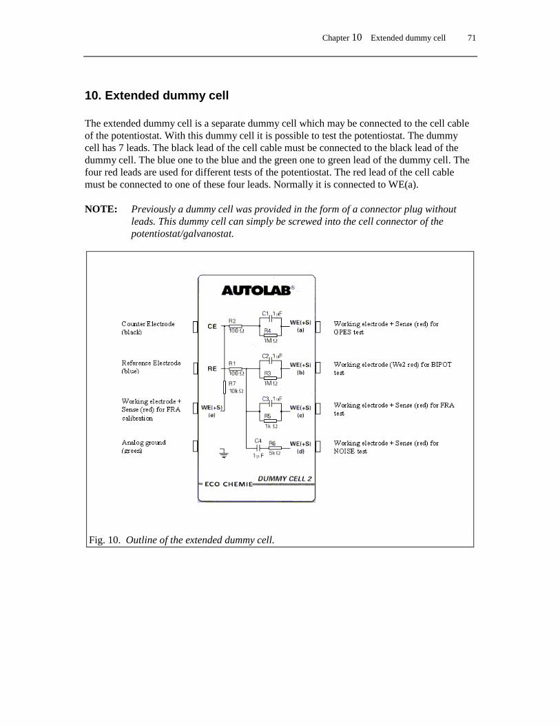
Chapter 10 Extended dummy cell 71
10. Extended dummy cell The extended dummy cell is a separate dummy cell which may be connected to the cell cable of the potentiostat. With this dummy cell it is possible to test the potentiostat. The dummy cell has 7 leads. The black lead of the cell cable must be connected to the black lead of the dummy cell. The blue one to the blue and the green one to green lead of the dummy cell. The four red leads are used for different tests of the potentiostat. The red lead of the cell cable must be connected to one of these four leads. Normally it is connected to WE(a). NOTE: Previously a dummy cell was provided in the form of a connector plug without
leads. This dummy cell can simply be screwed into the cell connector of the potentiostat/galvanostat.
Fig. 10. Outline of the extended dummy cell.


Chapter 11 Additional modules 73
11. Additional modules
11.1 Low current module ECD The ECD module(low current amplifier) can be used in applications where the measurement of low currents is needed. It will add two extra current ranges (100 pA and 1 nA) and thus lower the resolution of the instrument by a factor of 100. An internal Sallen-Key filter is available as well, so that noise can be filtered out. With the PGSTAT12, PGSTAT30 and PGSTAT100, the WE-connector of the cell cable is internally connected to the ECD, which means that the normal WE cell cable connection can be used. From the Manual Control window in the software, the ECD module can be switched on or off. In the same window also the ECD filter settings can be changed. The current ranges that are selectable when the ECD is active are 100 µA to 100pA. In practice the ECD module will be useful when the actual currents during the measurement are below 100 pA . The output of the low current module can be measured at the BNC-connector of the ECD module, indicated with I. The test of the ECD is described in the configuration and test chapter. NOTE: Do not load this output with an impedance lower than 1 kOhm.
11.2 Bipotentiostat module BIPOT The BIPOT module is meant for applications where a second working electrode(WE2) is needed with a fixed potential. In most cases this will be when rotating ring-disk experiments are being done. (The potential can be changed while the potential of the ring is fixed.) The maximum current that can be measured on WE2 is 35 mA, while the fixed potential that can be applied is between –5 V and +5 V. The current ranges of the bipotentiostat itself are from 100 nA to 10 mA. The use of automatic current ranging on the BIPOT will only be possible when automatic current raging is also used by the main potentiostat. The use of the module in the software is supported in chrono-methods as well as cyclic voltammetry, linear sweep voltammetry and steps and sweeps. In cases where a galvanostatic technique is used (chrono-potentiometry for example) the BIPOT will still function in potentiostatic mode. In the case of chrono-potentiometry (zero current) WE1 is at open circuit while WE2 will still be on a fixed potential. The settings for the BIPOT can be found in the Edit Procedure window on the bottom of Page 2. With the PGSTAT12, PGSTAT30 and PGSTAT100, the WE2-connector on the differential electrometer amplifier is used to connect the BIPOT to the second working electrode. The BNC connector indicated with I can be used to measure the output of the BIPOT module. In cases where a so-called scanning bipotentiostat is needed, where the potential of WE2 follows that of WE1, please contact your distributor or Eco Chemie. NOTE: Do not load this output with an impedance lower than 1 kOhm.
11.3 Module for impedance measurements FRA

74 Installation and Diagnostics Guide
All signals of the FRA2 module are internally redirected to and from the PGSTAT12, PGSTAT30 or PGSTAT100 module, so no extra installation needs to be done. There are three monitor plugs present on the FRA2 module, for making external connections:
V: output perturbation signal Y: input reference signal to be measured (E) X: input signal to be measured (I)
For a detailed description of the FRA module see the FRA manual.
11.4 Scan generator SCAN-GEN The SCAN-GEN module is an analog scan generator used for cyclic and linear sweep voltammetry. The generator is fully controlled from the PC. The connections to the potentiostat are made internally. This module is used with the standard Autolab modules for scan rates up to 10 V/s. For measurements at higher scan rates the ADC750 module is required.
Front panel indicators The front panel has one green indicator, which lights up when SCAN-GEN is in the "active" mode. This means, that its output to the PGSTAT and to the front panel is switched on and that SCAN-GEN is either scanning or in "hold" mode.
Front panel connections There is one BNC connector on the front panel, indicated with V, carrying the output signal from the scan generator. This is the same signal that is internally connected to the P(G)STAT for controlling the electrochemical cell. Load impedance of this output must be at least 5 kΩ, but a higher value is preferred. As the output impedance is 270 Ω, a correction must be made to the value measured at this output for input impedance’s lower than 250 kΩ.
Scan rates, vertex potentials, vertex count The maximum scan rate that can be applied with SCAN-GEN is 10 kV/s. Scan rates lower than 10 mV/s are not precise, due to drift of the internal integrator. The rising and falling slope of the signal may be set independently, as long as they are set within the same decade of scan rate. The vertex potentials (the two potential levels at which the scan will change direction) may be set at any level between ±5 V relative to the start potential, providing that the upper vertex potential is more positive than the lower vertex potential. The internal vertex counter will count up to 216 vertices or 215 scans. These specifications may be limited by the software controlling the module.
Digital control Digital settings are available for setting the vertex potential levels, the slope for the rising and falling part of the scan, the number of vertices, the initial scan direction, reversing the scan direction and holding the scan itself. All these settings are normally made through the Autolab software.

Chapter 11 Additional modules 75
11.5 Fast AD-converter ADC750 The ADC750 has two independent AD-converters and a maximum conversion speed of 750 kHz. The two channels can measure two signals simultaneously, e.g. both potential and current. The module should be used in cases where the sampling rate (max. 50 kHz) is not sufficient. This can be in chrono methods (interval times <.1 s) where short steps are applied and a large number of data points is needed in a short time. The shortest interval time when the ADC750 is used is 1.3 µs. In combination with the SCANGEN module the ADC750 module can also be used for cyclic voltammetry (linear scan) with high scan rates up to 10 kV/s. For both techniques the use of the ADC750 can be defined on Page 2 of the Edit Procedure window. In the Manual Control window the gain settings of the ADC750 can be defined, by selecting either a fixed gain value or automatic gain selection. NOTE: The module cannot be use in Chrono-Coulometry (interval times <.1 s).
11.6 Filter - Integrator module FI20 The FI20 is a combined filter and integrator module. The filter part can be used to filter out noise on the measurements in cases where it is impossible to remove the noise by the use of proper shielding of the cell and electrodes. The settings for the filter can be selected in the Manual Control window, where the RC time of the filter can be set to .1s, 1s or 5s. The filter part is available for all electrochemical techniques but cannot be used in combination with the ADC750 module. The integrator can be used in cases where an analog integrator is needed; chronocoulometry (interval time<.1s) and cyclic/linear sweep voltammetry(current integration). The settings for the integrator can be found in the Manual Control window, where the integrator time can be selected from 0.01s up to 10 s. Please note that a different current range will require a different integrator setting. The FI20 has two monitor connectors:
I: The filtered current output from the potentiostat. Q: The output of the integrator.
NOTE: Do not load these outputs with an impedance lower than 1 kOhm.
11.7 Module to connect Ion selective electrodes PX This module is used for pH measurements and bi-potentiometric (current-less) measurements. The measurements can be done in the electrochemical cell as well as in a separate cell. The connection to the pH or Ion selective electrode is made to the connector indicated with E. A LEMO-BNC adapter is delivered to connect Metrohm electrodes. The connector indicated with G should be short circuited with the BNC shunt when the pH or Ion selective electrode is placed in a separate cell. If the electrode is placed into the electrochemical cell (together with WE, S, CE and RE) the BNC shunt must be removed. The output of the pX module can be measured by activating the second signal option in GPES. Note that this module cannot be

76 Installation and Diagnostics Guide
used simultaneously with the BIPOT module. To switch between BIPOT and pX module you have to disable or enable the BIPOT module in the Hardware Setup.
11.8 Module to measure electrochemical noise ECN The ECN module is used for Timed Noise Monitoring experiments to measure low frequent differential potentials and currents at very high impedance, due to i.e. corrosion reactions. The current noise will be measured between two identical electrodes, while the potential noise is measured with respect to a reference electrode. The delivered Noise cable (100cm BNC-banana cable) must be connected to the connector indicated with E (Ein). The output of the ECN module can be monitored using the connector indicated with V (Vout). Vout =4(Ein-EoffsetDAC) The EoffsetDAC represents the open circuit potential at the start of the measurement. This potential is stored as offset on the DAC to compensate the DC component of the potential for measuring the low frequent differential noise potential with the highest resolution available. The cell connections should be made as explained in the next figure.
NOTE: Do not load the output with an impedance lower than 1 kOhm.
Fig. 11. Cell connections for Electrochemical Noise Measurements.
PGSTAT
WE2REWE1
ECN
RE S
E
red
WE
black
green
Noise cable
ground
CE (not connected)

Chapter 11 Additional modules 77
11.9 Multiplexing module MUX
SCNR and MULTI units The MUX module with attached units can accomplish the following tasks: • Performing measurements with multiple electrochemical cells (MULTI unit). • Performing measurements with multiple working electrodes in the same cell (SCNR unit). The MUX module is the same for all units. There are 3 types of units available:
MULTI4: to work with 4 different electrochemical cells (with 4 electrodes). SCNR16A: to work with 16 working electrodes in the same cell. SCNR8A: to work with 8 pairs of working-/ sense- electrodes in the same cell.
The units are designed so that they can be mounted on each other “head to tail”. In such manner, they can be stacked with units of the same type to extend the number of channels. Each extra unit adds 4, 8 or 16 channels, depending on its type. These modules will be delivered with one MUX cable, and each connector unit will include 16 electrode cables. Each electrode cable will be labelled with the appropriate channel number and function (WE, CE, RE or S).
Connections a. Connect the 15-pins D-connector between the MUX module and the first SCNR/MULTI
unit. b. Connect the 9-pins D-connector to the SCNR/MULTI unit. Make sure the screws are
tightened well in order to have a proper shielding. c. Connect the electrode cables from the PGSTAT to the corresponding contra-banana
connectors attached to the cable with the 9-pins D-connector that is plugged into the first SCNR/MULTI box.
d. If more than 1 connector unit is purchased, the additional boxes can be attached to the previous unit. Please note that the base channel numbers for multiple SCNR/MULTI-units are indicated at the bottom of the box. It is advised to stack the units in sequence.
e. Make the connections to electrochemical cell(s) with the corresponding electrode cables from the SCNR/MULTI connector unit(s).

78 Installation and Diagnostics Guide
Limitations • No BSTR10A or BSTR20A: the MUX units cannot tolerate 10A/20A • No PGSTAT100: because of safety considerations. MULTI4, SCNR8A: no further limitations SCNR16A: • No separate sense electrodes available
11.10 ARRAY The ARRAY module is used in combination with the PGSTAT10 potentiostat/galvanostat. Up to 5 ARRAY modules can be planted into one Autolab case. This gives the opportunity to measure the current response of up to 6 working electrodes. A working electrode of the electrochemical cell can be connected to the module by means of the BNC-connector marked with WE. The BNC connector indicated with Iout can be used to measure the output of the ARRAY module. The maximum current on each ARRAY is 35 mA, each of them can have independent current ranging. The potential applied to the additional working electrode is, in most cases, the same as applied to the main working electrode connected to the PGSTAT10. If extra offset DAC's are present there can be a constant potential with respect to the main working electrode. The ARRAY-module is used in combination with the GPES Multichannel software. NOTE: Do not load the outputs with an impedance lower than 1 kOhm.
Fig. 12. Connection of the MUX/SCNR and MUX/MULTI module.
To MUX-module in Autolab
Connect to cell cable of PGSTAT module
SCNR 1..16 or MULTI 1..4
SCNR 17..32 or MULTI 5..8
To electrochemical cell
SCNR …255 or MULTI ..96

Chapter 12 Additional equipment 79
12. Additional equipment
12.1 Booster BSTR10A or BSTR20A The BSTR10A or BSTR20A is used in combination with the PGSTAT30 or PGSTAT100. It is used for applications requiring more than 1 A output current. The instrument can be placed on top of Autolab or next to it. Connect the BSTR10A or BSTR20A in the following manner: 1. Exit the Autolab software and turn off the power of the Autolab and Booster. 2. Connect the cable with D-25 connector between the DIO P1 or DIO P2 connector at the
rear side of Autolab and the “digital control” of the Booster. 3. Replace the WE/CE cable with the cell cable that is connected to the Booster. 4. Enable the BSTR10A or BSTR20A option in the Hardware setup program. 5. Connect the cell cables to the electrochemical cell. When switching on the power of the booster, the manual cell switch will be in the 'off' position. After initialising the instrument by the measurement software on the computer, the manual switch on the front of the instrument must be set in 'on' position, which is shown by the LED. If the switch is 'off', this will be detected by the GPES software. As long as the Booster is connected to the PGSTAT30 or PGSTAT100, the manual cell switch of the PGSTAT30 or PGSTAT100 must be in the 'on' position. Otherwise the PGSTAT30 or 100 will show a voltage overload and the electrochemical cell may get an uncontrolled potential. This may lead to a damaged working electrode. The BSTR10A/20A is capable of delivering 10 A/ 20 A output current only if the yellow LED marked with 'booster active' is shown. If the booster is connected but not required, the 'booster active' LED will not be shown. In this mode, the cell cable from the PGSTAT30 or PGSTAT100 is internally connected directly to the cell. Please note that the cell switch of the Booster must be in position 'on'. Otherwise the PGSTAT30 or PGSTAT100 will be disconnected from the cell. The Iovl LED is shown in case the output current is close to 10 A or to 20 A. The Vovl LED lights up when the output voltage reaches its maximum of 20 V. If low currents are measured, it is advised to disconnect the BSTR10A and to make a direct connection from the PGSTAT30 or PGSTAT100 to the cell. The DVM of the PGSTAT30 or PGSTAT100 can be used to read potential and current. The Booster module can be controlled with the GPES-program for cyclic voltammetry and with the program for the chrono-methods. Also the FRA software supports the Booster.

80 Installation and Diagnostics Guide
In case the Booster is connected but not switched, the software will show a warning: "Cannot read Booster". After pressing 'Ignore', the measurement program will proceed. You can now do the measurement with the potentiostat. You have to connect the normal cell cable again in stead of the Booster cable (WE/CE).
12.2 Any equipment with -10..10 V output (second signal) The 'General Purpose Electrochemical System (GPES)'-software package provides the possibility to record an additional signal which is supplied to the 'Vin'-connector of the µAutolab (see appendix) or to the ADC 1 or 2 -connectors of the ADC164 of the Autolab with PGSTAT12, PGSTAT30 or PGSTAT100. This signal must be in the range -10 to 10 V.
12.3 Interface to Mercury Electrodes IME663, IME303 Several combinations are possible:
IME663 + Metrohm 663 VA Stand IME303 + DME IME303 + EG&G PAR303
The cable with the 25-pin D-connector (male) and the 15-pin D-connector (female) should be connected between the IME (connector marked 'DIO') and the Autolab (connector marked ‘DIO P1’)
Metrohm 663 VA Stand The 26-pole edge connector should be plugged into the rear side of the 663 VA Stand. The short green banana plug should be connected to the ground. The 9-pins D-connector on the other end of this cable must be plugged in the IME663 socket, marked ‘VA Stand’. For the µAutolab type II the remaining DIN connector should be inserted in the cell cable socket of the Autolab, replacing the standard cell-cable. For the PGSTAT12, PGSTAT30 and PGSTAT100, the cell cable is connected directly to the electrodes of the electrochemical cell. Please, lift the hood of the 663 VA Stand and disconnect the original electrode cables. Replace them with the connectors of the special cable that is supplied by the Autolab manufacturer. This cable should be connected to the banana-plugs of the original Autolab cell cable. For stirrer control with the IME663, the cable with the 5-pin DIN connectors is used. One end of this cable must be plugged into the plug marked 'STIRRER' on the IME663. The other end is plugged into the male DIN-connector E at the rear side of the 663 VA Stand. NOTE: The 663 VA Stand only operates properly under computer control when it is switched in SMDE mode.

Chapter 12 Additional equipment 81
EG&G PAR303 The cable with the 25-pin D-connector (female) and the 9-pin D-connector (male) is used to connect the EG&G electrode to the IME303. Use the connector marked with 'PAR303' at the rear side of the IME303. The 25-pin D-connector must be plugged into the 'J1'-connector at the rear side of the PAR303 electrode. To connect the cell-cable, use the adapters delivered with the IME303. These connectors fit into the sockets at the rear side of the PAR303.
DME A drop knocker can be controlled with the IME303. Use the banana sockets at the rear marked: ‘Solenoid’. Every time a ‘New Drop’ action takes place, a 15V pulse will be generated between the pins. The duration of this pulse can be changed using the option Electrode control, setup’ from the Utilities menu of GPES. The electrodes should connected directly to the Autolab cell cable.
12.4 Motorburettes
Metrohm Dosimat 665 or 765 A special cable with two or more 26-pin D-connectors can be used to control Metrohm Dosimat 665 or 765 burettes. It is possible to control up to 8 burettes. Plug the connector marked with DIO into the Autolab (rear side, marked DIO P2). The other connectors are marked with 1 to 8 indicating the burette number. The cable can be ordered for 1, 2, 4 and 8 burettes.
Schott T100/T90 A special cable with one or more 37-pin D-connectors and one 26-pin D-connector can be used to control Schott burettes. It is possible to control up to 8 burettes. Plug the 26-pin connector into the Autolab (rear side, marked DIO P2). The other connectors are marked with 1 to 8 indicating the burette number. The cable can be ordered for 1, 2, 4 and 8 burettes.
12.5 External Rotating Disk Electrode (RDE) A Rotating Disk Electrode (RDE) that has the opportunity to control the rotation speed by an external voltage level, can be connected to either DAC channel 1 or DAC channel 2 for the Autolab or to Vout of the µAutolab type II. The input of the RDE must be in the range -10 V.. 10 V. The configuration and usage are explained in the RDE-control paragraph of the GPES manual. Please select DAC channel with care: DAC channel 1 may be in use by the BIPOT, ARRAY or ECD module. Do not use these modules together with RDE control. DAC channel 2 may be used for AC-voltammetry, and may therefore result in incorrectly applied potentials on the potentiostat. Contact your distributor if you need more information.


Chapter 13 Configuration and test 83
13. Configuration and test
13.1 Configuration and test of GPES software
Test of Autolab Switch on the Autolab and computer. • Wait until Windows is running. • Select ‘Autolab Software' from the Windows Start menu. • Startup Hardware Setup by clicking ‘Hardware’. • Check the Autolab configuration. If you have an Autolab with PGSTAT10, PGSTAT12,
PGSTAT30 or PGSTAT100 inspect your front panels for the proper module configuration. When you choose the µAutolab or µAutolab type II, the proper modules are selected automatically. For details on the hardware configuration see the 'Hardware configuration' paragraph of this chapter.
• Press OK when done. • Select ‘Autolab Software' from the Windows Start menu. • Startup GPES. • Wait until GPES is running. • Connect dummy cell to potentiostat module with the cell cable. Connect the working
electrode to WE(a). • Select 'Method' from the main menu • Select the 'Cyclic voltammetry (staircase)' - 'Normal' sub item • Wait until GPES has updated its windows • Select 'File' from the main menu • Select 'Open procedure' • Load the procedure named TESTCV.ICW from the \AUTOLAB\TESTDATA folder • Make sure that the cell-switch of the potentiostat is on • Press the Start button (bottom left corner) to start the measurement test • After the measurement, your graph on the screen should look like the following graph:
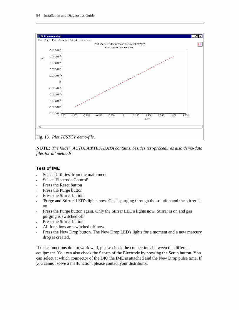
84 Installation and Diagnostics Guide
Fig. 13. Plot TESTCV demo-file. NOTE: The folder \AUTOLAB\TESTDATA contains, besides test-procedures also demo-data files for all methods.
Test of IME • Select 'Utilities' from the main menu • Select 'Electrode Control' • Press the Reset button • Press the Purge button • Press the Stirrer button • 'Purge and Stirrer' LED's lights now. Gas is purging through the solution and the stirrer is
on • Press the Purge button again. Only the Stirrer LED's lights now. Stirrer is on and gas
purging is switched off • Press the Stirrer button • All functions are switched off now • Press the New Drop button. The New Drop LED's lights for a moment and a new mercury
drop is created. If these functions do not work well, please check the connections between the different equipment. You can also check the Set-up of the Electrode by pressing the Setup button. You can select at which connector of the DIO the IME is attached and the New Drop pulse time. If you cannot solve a malfunction, please contact your distributor.
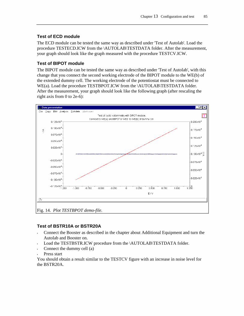
Chapter 13 Configuration and test 85
Test of ECD module The ECD module can be tested the same way as described under 'Test of Autolab'. Load the procedure TESTECD.ICW from the \AUTOLAB\TESTDATA folder. After the measurement, your graph should look like the graph measured with the procedure TESTCV.ICW.
Test of BIPOT module The BIPOT module can be tested the same way as described under 'Test of Autolab', with this change that you connect the second working electrode of the BIPOT module to the WE(b) of the extended dummy cell. The working electrode of the potentiostat must be connected to WE(a). Load the procedure TESTBPOT.ICW from the \AUTOLAB\TESTDATA folder. After the measurement, your graph should look like the following graph (after rescaling the right axis from 0 to 2e-6):
Fig. 14. Plot TESTBPOT demo-file.
Test of BSTR10A or BSTR20A • Connect the Booster as described in the chapter about Additional Equipment and turn the
Autolab and Booster on. • Load the TESTBSTR.ICW procedure from the \AUTOLAB\TESTDATA folder. • Connect the dummy cell (a) • Press start You should obtain a result similar to the TESTCV figure with an increase in noise level for the BSTR20A.
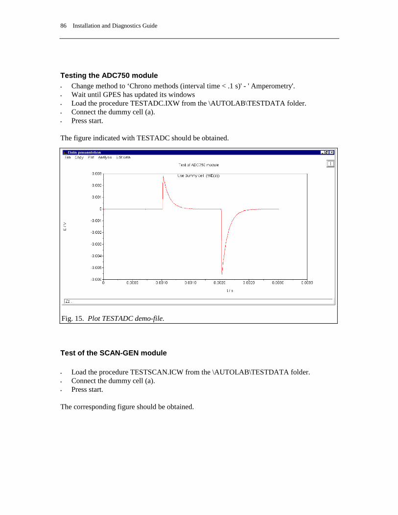
86 Installation and Diagnostics Guide
Testing the ADC750 module • Change method to ‘Chrono methods (interval time < .1 s)' - ' Amperometry'. • Wait until GPES has updated its windows • Load the procedure TESTADC.IXW from the \AUTOLAB\TESTDATA folder. • Connect the dummy cell (a). • Press start. The figure indicated with TESTADC should be obtained.
Test of the SCAN-GEN module • Load the procedure TESTSCAN.ICW from the \AUTOLAB\TESTDATA folder. • Connect the dummy cell (a). • Press start. The corresponding figure should be obtained.
Fig. 15. Plot TESTADC demo-file.
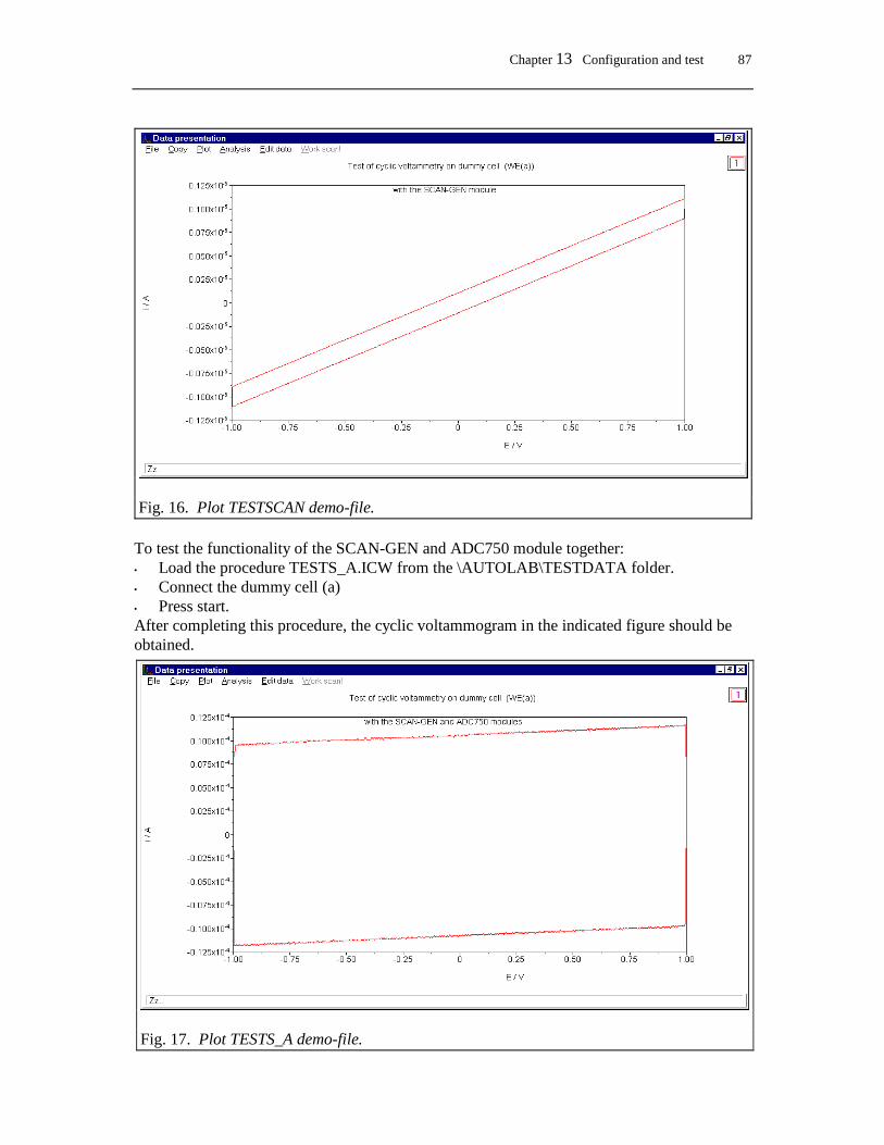
Chapter 13 Configuration and test 87
To test the functionality of the SCAN-GEN and ADC750 module together: • Load the procedure TESTS_A.ICW from the \AUTOLAB\TESTDATA folder. • Connect the dummy cell (a) • Press start. After completing this procedure, the cyclic voltammogram in the indicated figure should be obtained.
Fig. 16. Plot TESTSCAN demo-file.
Fig. 17. Plot TESTS_A demo-file.
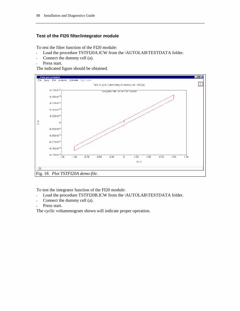
88 Installation and Diagnostics Guide
Test of the FI20 filter/integrator module To test the filter function of the FI20 module: • Load the procedure TSTFI20A.ICW from the \AUTOLAB\TESTDATA folder. • Connect the dummy cell (a). • Press start. The indicated figure should be obtained.
To test the integrator function of the FI20 module: • Load the procedure TSTFI20B.ICW from the \AUTOLAB\TESTDATA folder. • Connect the dummy cell (a). • Press start. The cyclic voltammogram shown will indicate proper operation.
Fig. 18. Plot TSTFI20A demo-file.
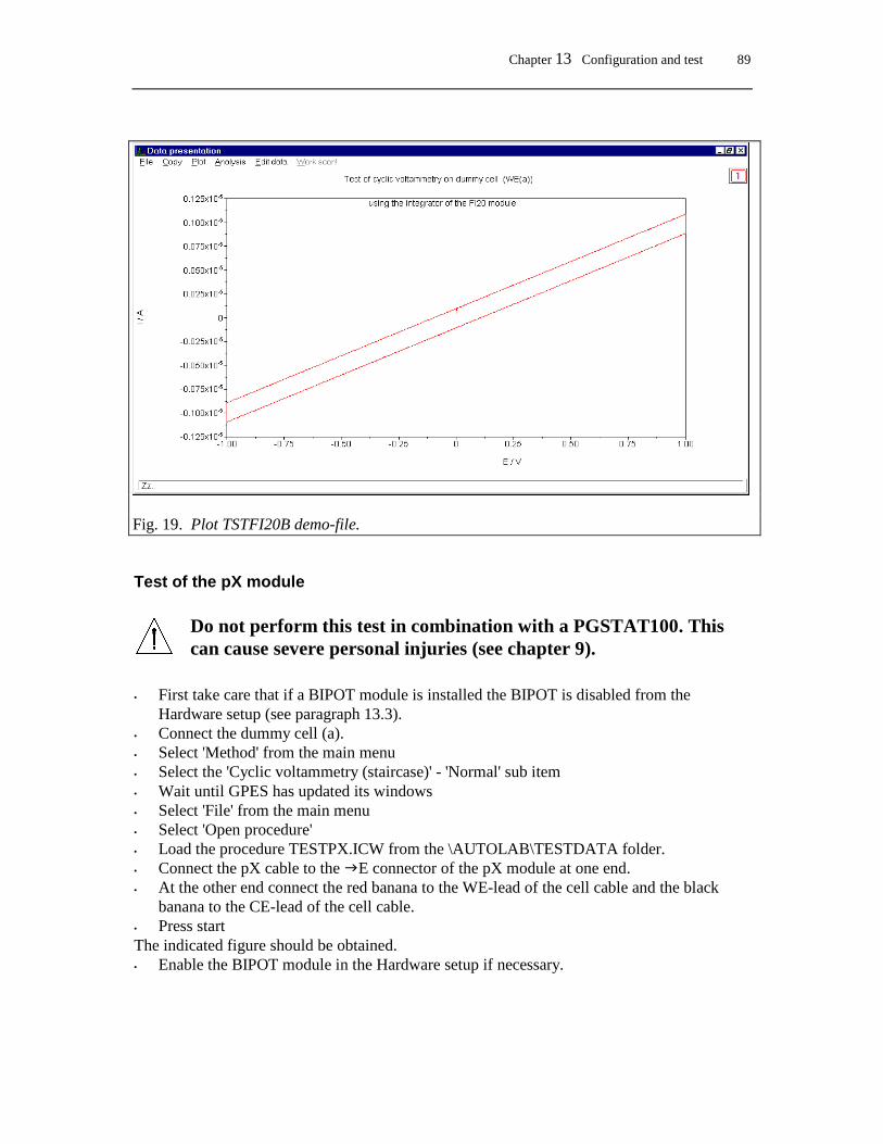
Chapter 13 Configuration and test 89
Test of the pX module
Do not perform this test in combination with a PGSTAT100. This can cause severe personal injuries (see chapter 9).
• First take care that if a BIPOT module is installed the BIPOT is disabled from the
Hardware setup (see paragraph 13.3). • Connect the dummy cell (a). • Select 'Method' from the main menu • Select the 'Cyclic voltammetry (staircase)' - 'Normal' sub item • Wait until GPES has updated its windows • Select 'File' from the main menu • Select 'Open procedure' • Load the procedure TESTPX.ICW from the \AUTOLAB\TESTDATA folder. • Connect the pX cable to the E connector of the pX module at one end. • At the other end connect the red banana to the WE-lead of the cell cable and the black
banana to the CE-lead of the cell cable. • Press start The indicated figure should be obtained. • Enable the BIPOT module in the Hardware setup if necessary.
Fig. 19. Plot TSTFI20B demo-file.

90 Installation and Diagnostics Guide
Test of the ECN module
Do not perform this test in combination with a PGSTAT100. This can cause severe personal injuries (see chapter 9).
• First take care that if a BIPOT module is installed the BIPOT is disabled from the
Hardware setup (see paragraph 13.3). • Connect the dummy cell (a). • Select 'Method' from the main menu • Select the 'Cyclic voltammetry (staircase)' - 'Normal' sub item • Wait until GPES has updated its windows • Select 'File' from the main menu • Select 'Open procedure' • Load the procedure TESTECN.ICW from the \AUTOLAB\TESTDATA folder. • Connect the delivered BNC cable (25cm) to the V of the ECN module at one end and to
ADC164 channel 1 (old cabinet channel 3) at the other end. • Connect the ECN cable to the E connector of the ECN module at one end. • At the other end connect the red banana to the WE-lead of the cell cable and the black
banana to the CE-lead of the cell cable. • Press start The indicated figure should be obtained. • Enable the BIPOT module in the Hardware setup if necessary.
Fig. 19a. Plot TESTPX demo-file.
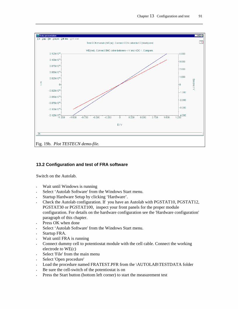
Chapter 13 Configuration and test 91
13.2 Configuration and test of FRA software Switch on the Autolab. • Wait until Windows is running • Select ‘Autolab Software' from the Windows Start menu. • Startup Hardware Setup by clicking ‘Hardware’. • Check the Autolab configuration. If you have an Autolab with PGSTAT10, PGSTAT12,
PGSTAT30 or PGSTAT100, inspect your front panels for the proper module configuration. For details on the hardware configuration see the 'Hardware configuration' paragraph of this chapter.
• Press OK when done • Select ‘Autolab Software' from the Windows Start menu. • Startup FRA. • Wait until FRA is running • Connect dummy cell to potentiostat module with the cell cable. Connect the working
electrode to WE(c) • Select 'File' from the main menu • Select 'Open procedure' • Load the procedure named FRATEST.PFR from the \AUTOLAB\TESTDATA folder • Be sure the cell-switch of the potentiostat is on • Press the Start button (bottom left corner) to start the measurement test
Fig. 19b. Plot TESTECN demo-file.
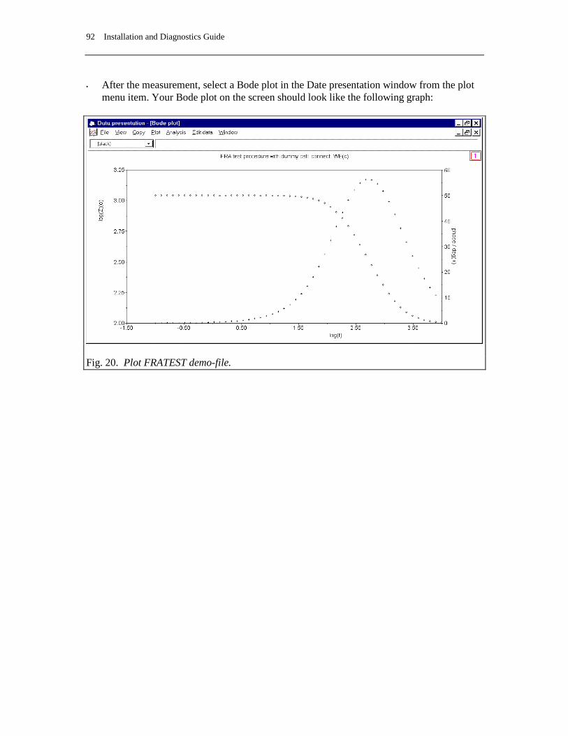
92 Installation and Diagnostics Guide
• After the measurement, select a Bode plot in the Date presentation window from the plot menu item. Your Bode plot on the screen should look like the following graph:
Fig. 20. Plot FRATEST demo-file.
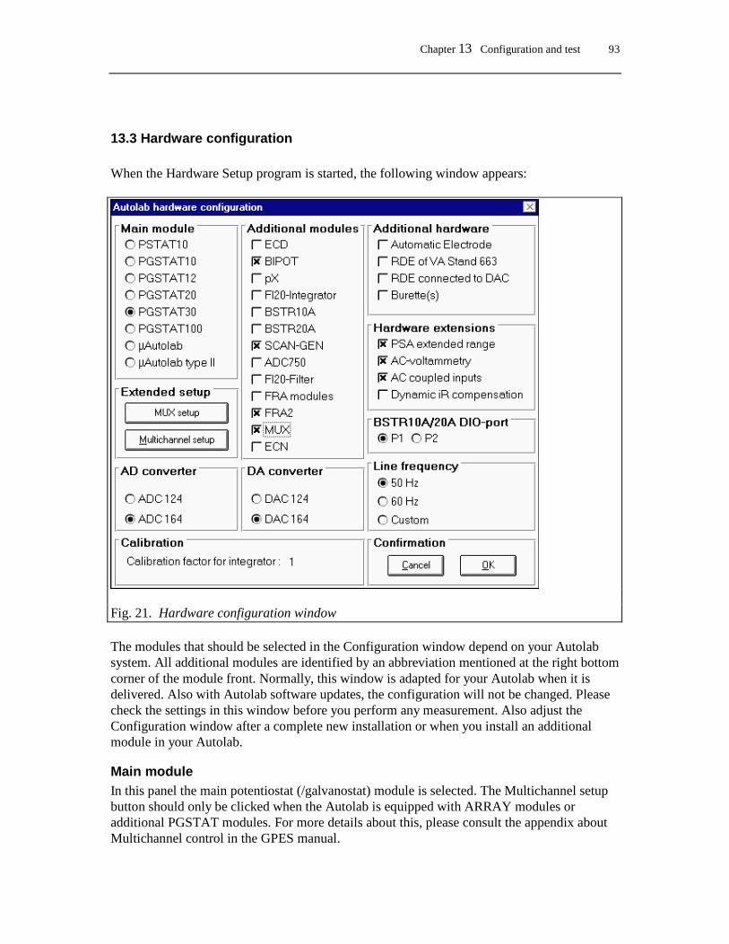
Chapter 13 Configuration and test 93
13.3 Hardware configuration When the Hardware Setup program is started, the following window appears:
Fig. 21. Hardware configuration window The modules that should be selected in the Configuration window depend on your Autolab system. All additional modules are identified by an abbreviation mentioned at the right bottom corner of the module front. Normally, this window is adapted for your Autolab when it is delivered. Also with Autolab software updates, the configuration will not be changed. Please check the settings in this window before you perform any measurement. Also adjust the Configuration window after a complete new installation or when you install an additional module in your Autolab.
Main module In this panel the main potentiostat (/galvanostat) module is selected. The Multichannel setup button should only be clicked when the Autolab is equipped with ARRAY modules or additional PGSTAT modules. For more details about this, please consult the appendix about Multichannel control in the GPES manual.

94 Installation and Diagnostics Guide
Additional modules The items in this panel are modules that are present in the Autolab, except for the BSTR10A or BSTR20A, which are placed as a separate box on top of, or besides the Autolab. Checking a module that is not present in the Autolab can lead to wrong measurements. The integrator module is default present in the PSTAT10/PGSTAT10, µAutolab and µAutolab type II and is automatically checked when this Main module is selected. The integrator item is changed to FI20-Integrator when you select the PGSTAT12, PGSTAT20, PGSTAT30 or PGSTAT100. The µAutolab and µAutolab type II are not equipped with the possibility to insert additional modules.
BSTR10A/20A DIO-port Select the connector of the DIO to which the BSTR10A or BSTR20A module is connected (rear side, DIO P1 or DIO P2).
Additional hardware
Automatic electrode See the paragraph about the Interface to mercury electrodes (IME303 and IME663) in this manual.
Rotating Disk Electrode of VA-Stand 663 This option gives the possibility to use the Metrohm VA-stand module as a rotating disk electrode. If this item is checked, the stirrer of the VA-Stand is switched on during the measurement.
RDE connected to DAC This option gives the opportunity to control a rotating disk electrode by the DAC-module. See the paragraph about RDE-control in the GPES manual.
Hardware extensions Hardware extensions are extensions made in the Autolab system. These extensions are not present in all Autolab systems. The extensions for PSA extended range and AC-voltammetry are tested with the Diagnostics program when selected.
PSA extended range If this extension is present it is possible to perform Potentiometric Stripping Analysis measurements with a larger potential range: without extended range: -1..1 Volt with extended range: - PGSTAT10/µAutolab type II -2..2 Volt - PGSTAT20/PGSTAT12/30/100 -2.5..2.5 Volt - PSTAT10 -4..4 Volt

Chapter 13 Configuration and test 95
AC-voltammetry If this extension is present the option AC-voltammetry and AC-2nd harmonic becomes present in the method menu for Voltammeteric analysis.
AC-coupled inputs This hardware extension can be made on demand and is used in AC-voltammetry. The E and I outputs of the potentiostat are uncoupled for the DC-component in the signal.
Dynamic iR-compensation This hardware extension enables dynamic iR-compensation in the method menu for Cyclic Voltammetry (normal), Linear sweep voltammetry (normal), Chrono-amperometry > .1 s and Chrono-coulometry> .1 s.
AD converter See the front of the Autolab.
DA converter See the front of the Autolab.
Line frequency In order to reduce noise, the measured signals from the Autolab are averaged during one cycle of the line frequency. To get the best signal/noise performance you have to specify the line frequency present in your country.
Calibration
Calibration factor for integrator The integrator present in the µAutolab, µAutolab type II, PSTAT10, PGSTAT10 and in the FI20 module must be calibrated. The calibration factor is determined by the Diagnostics program


Chapter 14 Connecting an analog potentiostat 97
14. Connecting an analog potentiostat Make the following connections: 1. Connect channel 1 and channel 2 of the DAC164 to the Input Control of the analog
potentiostat by means of BNC cables. Please note that the shield of the BNC cable is connected to the analog ground.
2. Connect Current Output of the analog potentiostat to channel 1 of the ADC164 module,
by means of a BNC cable. 3. Connect Potential Output of the analog potentiostat to channel 2 of the ADC164 module,
by means of a BNC connector. All buttons and knobs of the potentiostat/galvanostat must be operated by hand. Using the GPES software: 1. Since Autolab cannot control the current range, the specified current range must be fixed
and if possible correspond to the current range of the analog potentiostat/galvanostat. If this is not possible, the report program allows to multiply the recorded current by a constant (see report program: Edit Work File). According to the specifications of Wenking, the voltage output of the current to voltage converter corresponds to 0.2 V full scale. The software assumes 1 V full scale. So this means that the scaling of the current axis on the screen is always wrong by a factor of 5, even in the case the selected current range corresponds to the specified current range in the input screens of the GPES software.
2. The input file called SYSDEF40.INP must be modified. Please follow the next steps: • make a back-up of the present SYSDEF40.INP file in the \AUTOLAB folder: copy SYSDEF40.INP in SYSDEF40.AUT copy SYSDEF40.INP to SYSDEF40.WEN • Change the file SYSDEF40.WEN by using a standard ASCII editor like Notepad. Record 32, item 1 must be 1 instead of 2 Record 15, item 1 must be 3 instead of 1 or 15 Record 15, item 3 must be 4 instead of 2 or 16 Record 12, item 1 must be 3 instead of 1 Record 12, item 2 must be 4 instead of 2 3. When the analog potentiostat/galvanostat is used, copy the proper system definition file: copy SYSDEF40.WEN to SYSDEF40.INP

98 Installation and Diagnostics Guide
4. When the Autolab potentiostat/galvanostat PGSTAT12, PGSTAT30 or PGSTAT100 is used, copy the proper system definition file:
copy SYSDEF40.AUT to SYSDEF40.INP

Chapter 15 Troubleshooting 99
15. Troubleshooting
15.1 System test (Diagnostics) If an error occurs during installation you can test the system with the Diagnostics program. The program is present in the Autolab software Program group. Click the shortcut Diagnostics in the Autolab software Program group to activate the diagnostic program. The program asks for the used dummy cell. If a printer is attached the output is optionally redirected to the printer. Necessary equipment is: • one BNC-cable (not for µAutolabs, standard delivered with each Autolab) • the Autolab dummy-cell. The Diagnostics program is self-explanatory. When the program reports an error, try to solve the problem with the hints given on the screen. If you cannot solve the malfunction, please send the printout of the report to your distributor.
15.2 Changing system definition Each Autolab application needs a file in which the different configurations of the Autolab-system are described. In some cases you have to change this so-called 'System Configuration' file SYSDEF40.INP in order to get a proper operation of your Autolab-system. This System Configuration file is also sometimes called the Hardware configuration file. Generally it is not necessary to change this file. Most of the relevant items can be changed by using the configuration setup of the different software packages. If you have to change this file anyhow, you can use a standard ASCII editor such as Notepad MS-Windows. All records in this file are divided into 5 items. The items are separated by commas. The records and items of SYSDEF40.INP are described in the file SYSDEF40.TXT in the \AUTOLAB folder.
15.3 FRA2 calibration file Each Autolab equipped with an FRA2 module needs a file called Fra2Cal.ini. This file is delivered with the Autolab software which came with the instrument. This file should be present in the \AUTOLAB folder. The Fra2Cal.ini file includes a serial number. This serial number is compared with the serial number of the Autolab and if they do not match the next message will appear.
“Calibration file for serial number AUT70xxx does not match the Autolab serial number AUT70xxx. Please load proper calibration file.”
The calibration file is present in the \INSTALL\DISK1 folder of the installation CD-ROM. If you cannot recover from this error please contact your distributor.


Chapter 16 Noise consideration 101
16. Noise consideration Since the electrochemical cell is placed externally and the potentiostats PGSTAT10, PGSTAT12, PGSTAT30, PGSTAT100 and µAutolab type II are capable of measuring low level currents at High Speed, the total system is susceptible to noise. Especially 'noise' with a frequency of the mains power, can cause severe disturbance in the measurements. The simplest way is to monitor the current output, available at the monitor cable of Autolab (BNC-connector IO) or at the BNC Iout at the rear side of the µAutolab type II, on an oscilloscope. Run the GPES for Windows package. Obtain the noise level on the oscilloscope at a time-base of 5 or 10 ms per division. When an oscilloscope is not available, the Check cell option from the Utilities sub-menu can be used. Instead of an oscilloscope, the screen is used to monitor the noise level. After the measurement some hints are given on the screen.
Problems with reference electrode If the reference electrode is not filled properly with electrolyte solution or when it has for other reasons a very high impedance, it will be expressed as noise. In most cases the applied potential is not the same as the measured potential. The Check cell option of the GPES package also checks the applied and measured potential. Please check your reference electrode or use another one.
Unshielded electrode cables It is not advisable to use unshielded electrode cables. Make the connections to the electrodes as close as possible to the electrode itself. Prevent using unshielded extension cables to the electrodes.
Faraday cage The use of a Faraday cage is always recommended. It protects the cell from external noise interference. Connect the cage to the green ground-connector of the cell cable or to ground connector GND at rear of the Autolab instrument.
Grounding of Autolab and PC Not proper grounding of the Autolab and PC will decrease the signal to noise ratio. Always use a grounded power-point and grounded power-cables. Be sure you connect the Autolab and PC to the same power ground. This means they should be connected to the same outlet.
Magnetic stirrer In some cases a magnetic stirrer can cause noise problems. Try the measurements with the stirrer on and off and monitor the current. If the stirrer causes a lot of noise please try to find another way of stirring.

102 Installation and Diagnostics Guide
Position of the cell, Autolab, IME The signal to noise ratio can often be improved by changing the positions of the cell or Autolab. The optimal positions can easily be found by varying the positions and monitoring the current. Switch on the cell after connecting the cell. Apply a potential at which the current is as low as possible. Select the lowest possible current range at which no current overload occurs. The dominant frequency will most probably be 50 Hz. Now try to change the positions of the cell, IME, PC, Autolab or the printer. Often the noise level can be optimised simply by changing the position of the cell and the position of the cell cable. Another source of noise problems is interference with other electrical cables, for instance the cable between the automatic mercury electrode and the IME or a printer cable. In general the electrochemical cell should be placed as far as possible from the computer and printer. If the noise level remains too high, a Faraday cage may be necessary.

Chapter 17 Consequences of the digital base of Autolab 103
17. Consequences of the digital base of Autolab It is clear that the digital nature of the instrument has consequences for the measurements. The consequences for the different techniques are: • The minimum potential step or pulse in all techniques is 150 µV. • All potential steps are rounded to the nearest possible value, thus an integer times 150 µV.
Where necessary, the specified potentials and potential steps are re-calculated. Thus specified values can be altered.
• In differential pulse and square wave voltammetry, the minimum amplitude is 2,5 mV. • In cyclic voltammetry, the interval time or time between two potential steps equals (step
potential/scan rate). The response of the electrochemical cell, current, charge or potential is recorded digitally. Therefore the resolution of the measurements is also limited. The actual resolution depends on the technique and on the amplitude of the signal. Since the AD-converter is equipped with a software programmable amplifier, the absolute resolution depends on the gain of the amplifier. The gains used are 1, 10 and 100 times the input signal. The GPES for Windows program will switch automatically between the gain 1 and 10. It is possible to select the gain 100 also by pressing the High sensitivity button in the Manual control window of the GPES package. With High sensitivity on the program will switch automatically between gain 1, 10 and 100. This, however, can cause problems when high frequencies (Square wave voltammetry), high scan rates (Cyclic voltammetry) and low interval times (Chrono methods) are necessary. The switching between the three gains can cause timing problems. The High sensitivity option can also cause problems with 'noisy' electrochemical cells. When the signal is very noisy the program cannot decide on which gain the current (or potential) can be measured an will select a random gain. This sometimes leads to a 'double' curve on the screen. Gain 10 (and 100 with High sensitivity on) is used when the level of response is low enough. When the absolute value of the current is higher then (0.75 * current range), the resolution of the current measurement equals:
(current range) * 20 = 0.0003 *(current range)
65536

104 Installation and Diagnostics Guide
When the absolute value of the current is below (0.75 * current range), the resolution equals: When the absolute value of the current is below (0.075 * current range), the resolution equals: The effect of the limited resolution can be seen, for instance when low currents are measured at a high current range. In such cases a lower current range has to be applied, if possible.
Fig. 22. The effect of the limited resolution. This square wave voltammogram is recorded at a too high current range, with relatively high back ground current, due to the use of a non-ideal solid electrode. Differential techniques, i.e. differential pulse and square wave voltammetry, may show resolution problems at much lower plotted current levels. However, remember that in those cases, the plotted current is the difference between two measured currents, each with its own
(current range) * 20 = 0.00003 *(current range)
65536
(current range) * 20 = 0.000003 *(current range)
65536

Chapter 17 Consequences of the digital base of Autolab 105
maximum resolution. When separate current levels are high, but their difference is small, a voltammogram as shown in the displayed figure can be measured. Some methods provide the possibility of derivation of the measured curve. In this case, the effect of the limited resolution of the measurements is magnified. Some methods provide an autoranging option. When autoranging is applied, the most optimal current range is selected automatically. But be careful using this option when: • High frequency square wave voltammetry is applied. • High scan rates in cyclic and linear sweep voltammetry are applied. Switching of the current range takes about 0.5 ms to 2 ms. Therefore an erroneous point can be measured when the current range is switched. Mostly, this error can be corrected by smoothing the plot afterwards. In the AC-voltammetry mode of the electroanalysis program an approximated sinusoidal perturbation is applied. A series of 1024 DAC values, representing one or more sinus perturbations, is applied with a speed depending on the required frequency. For every applied DAC-value the current is sampled. After a Fast Fourier Transformation on the applied potential and sampled current the real and imaginary part of the impedance is obtained.


Appendix I Connections to the different types of Autolab instruments 107
Appendix I Connections to the different types of Autolab instruments
Fig. A1. The front panel of the µAutolab type II.

108 Installation and Diagnostics Guide
Fig. A2. The rear panel of the µAutolab type II.

Appendix I Connections to the different types of Autolab instruments 109
Fig. A3. The front panel of the Autolab with PGSTAT10.
A : signal selector for front display B : signal source indicator for front display C : N/A D : cell on/off indicator E : cell cable connector for all electrodes F : front display G : cell on/off switch H : indicator for current ranges I-L : Autolab modules M : digital port 2 N : digital port 1 O : dc power supply for external devices P : power switch

110 Installation and Diagnostics Guide
Fig. A4. The rear panel of the Autolab with PGSTAT10.
A : power cord connector with fuse box B : ground connector C : shielded fan opening D,E : analog signal connectors F : interface cable connector
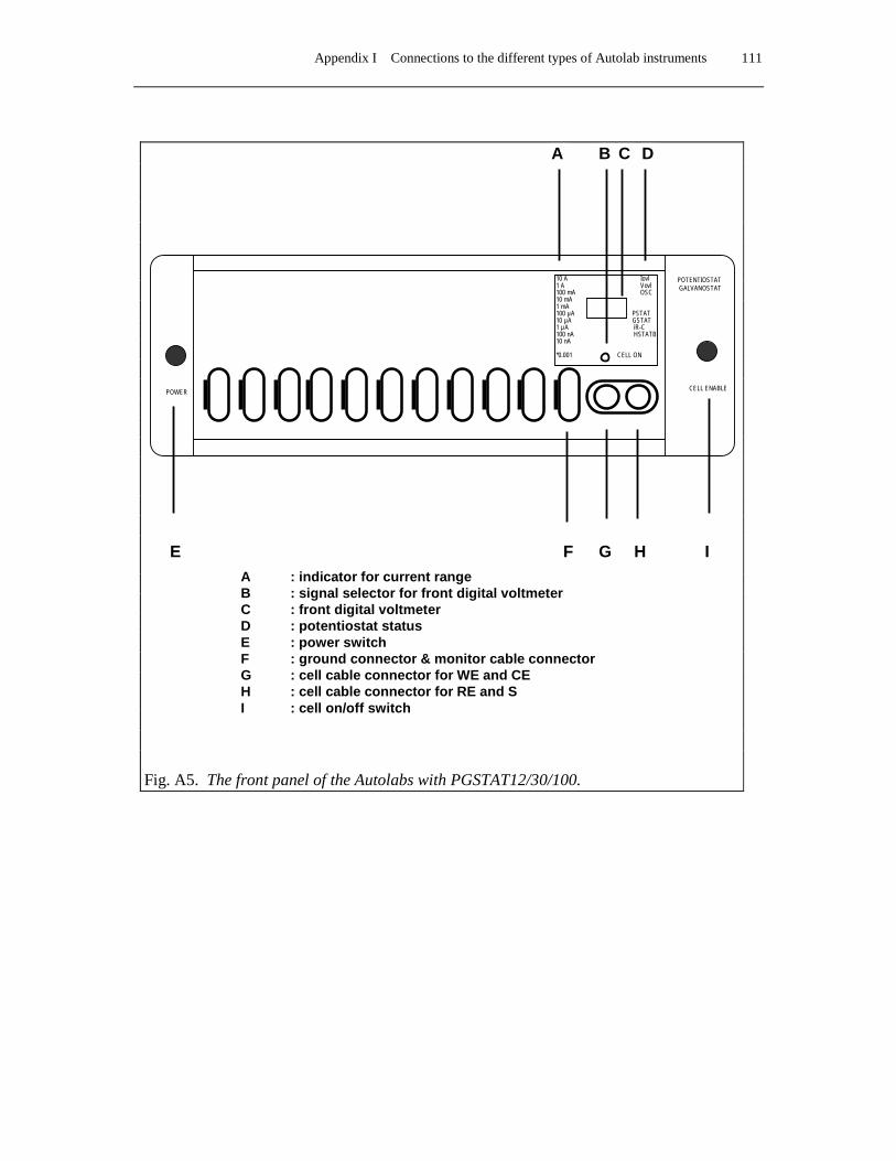
Appendix I Connections to the different types of Autolab instruments 111
Fig. A5. The front panel of the Autolabs with PGSTAT12/30/100.
POWER
10 A Iovl 1 A Vovl 100 mA OSC 10 mA 1 mA 100 µA PSTAT 10 µA GSTAT 1 µA iR-C 100 nA HSTATB 10 nA *0.001 CELL ON
CELL ENABLE
POTENTIOSTAT GALVANOSTAT
E F G H I
A B C D
A : indicator for current range B : signal selector for front digital voltmeter C : front digital voltmeter D : potentiostat status E : power switch F : ground connector & monitor cable connectorG : cell cable connector for WE and CE H : cell cable connector for RE and S I : cell on/off switch
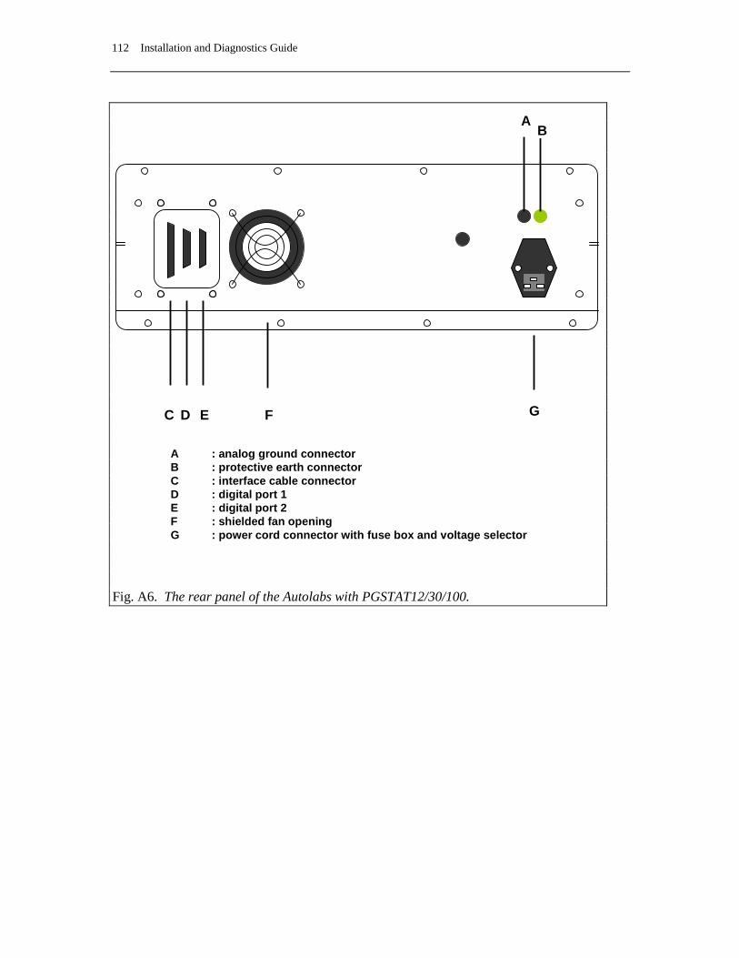
112 Installation and Diagnostics Guide
Fig. A6. The rear panel of the Autolabs with PGSTAT12/30/100.
A B
C D E F G
A : analog ground connector B : protective earth connector C : interface cable connector D : digital port 1 E : digital port 2 F : shielded fan opening G : power cord connector with fuse box and voltage selector

Appendix I Connections to the different types of Autolab instruments 113
Fig. A7. The rear panel of the Autolab-USB with PGSTAT12/30/100.
A B
C
E
D F G
A : analog ground connector B : protective earth connector C : USB cable connector D : USB hub cable connectors (to connect mouse, keyboard etc..) E : digital port 1 and digital port 2 F : shielded fan opening G : power cord connector with fuse box and voltage selector


Index 115
Index µ
µAutolab 39, 98 µAutolab type II 7, 39, 41, 42, 98, 105, 111, 112 µAutolab-USB 12
A
AC-coupled inputs 99 AC-voltammetry 98, 99, 109 ADC164 9, 84, 101 ADC750 7, 76, 77, 91 AD-converter 77, 107 Add New Hardware Wizard 23 additional modules 98 Adminstrator 17 analog ground 39, 40, 43, 44, 47, 55, 65, 101 analog input signal 10 ARRAY 81, 82, 97 Autolab Interface 28, 32, 36 Autolab Interface Board 15 Autolab interface software 21 Autolab Programs 20 Autolab-USB 10, 12 Autolab-USB Interface box 10, 11 Automatic electrode 98 auxiliary or counter electrode 39, 43, 47, 55, 65
B
backup 20 bandwidth 40, 44, 48, 49, 51, 56, 57, 59, 67, 68, 69 base address 13, 14, 15 batteries 41, 45, 52, 60, 70 BIPOT 7, 75, 78, 86, 89 BNC connectors 40, 44, 48, 56, 66 BNC shunt 78 booster 83 BSTR10A 7, 81, 83, 98 BSTR20A 7, 81, 83, 89, 98 burette 7, 10, 85
C
calibration 99 calibration file 103 Cannot Read Autolab 15 CD-Rom 17 cell cable 39, 43 cell pod 47, 55, 64 Chrono-amperometry 99 Chrono-coulometry 99 clean Autolab 42, 46, 54, 62 common mode voltage 41, 45, 52, 60, 70 Configuration and test 8 counter electrode 10 current range 10, 39, 43, 47, 48, 51, 52, 54, 55, 56, 59, 60, 62, 65, 66, 68, 69, 72, 101, 106, 107, 108, 109 current-less 78
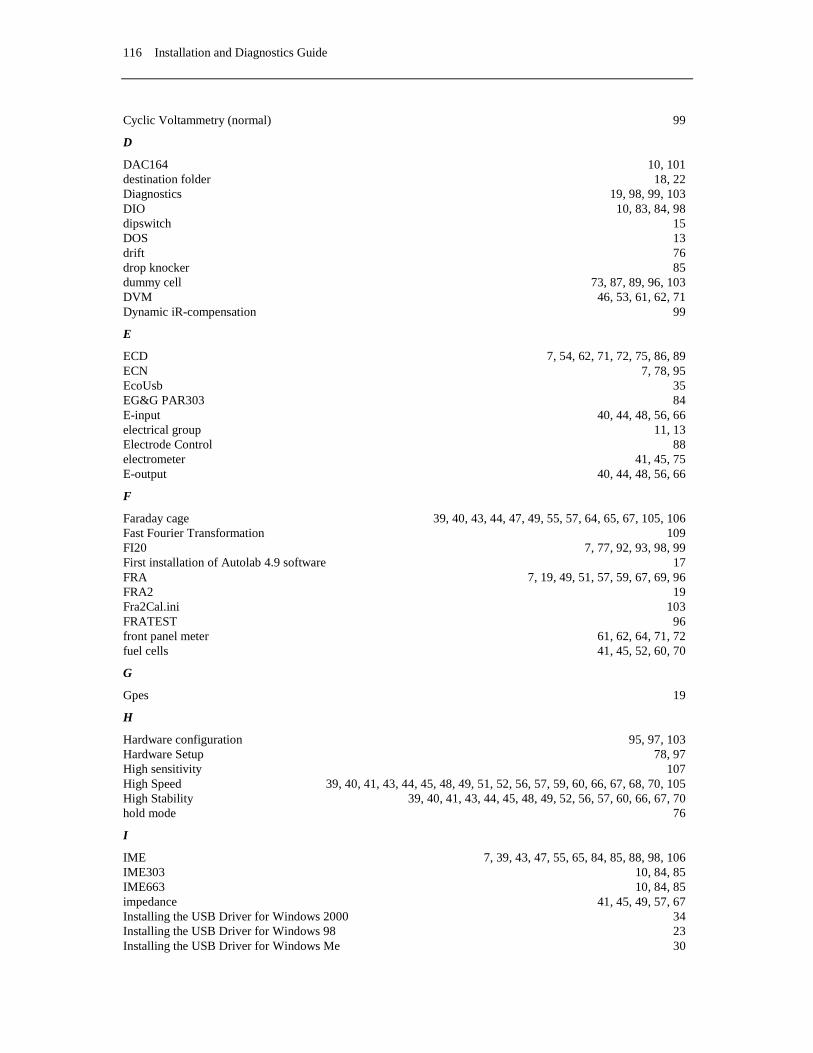
116 Installation and Diagnostics Guide
Cyclic Voltammetry (normal) 99
D
DAC164 10, 101 destination folder 18, 22 Diagnostics 19, 98, 99, 103 DIO 10, 83, 84, 98 dipswitch 15 DOS 13 drift 76 drop knocker 85 dummy cell 73, 87, 89, 96, 103 DVM 46, 53, 61, 62, 71 Dynamic iR-compensation 99
E
ECD 7, 54, 62, 71, 72, 75, 86, 89 ECN 7, 78, 95 EcoUsb 35 EG&G PAR303 84 E-input 40, 44, 48, 56, 66 electrical group 11, 13 Electrode Control 88 electrometer 41, 45, 75 E-output 40, 44, 48, 56, 66
F
Faraday cage 39, 40, 43, 44, 47, 49, 55, 57, 64, 65, 67, 105, 106 Fast Fourier Transformation 109 FI20 7, 77, 92, 93, 98, 99 First installation of Autolab 4.9 software 17 FRA 7, 19, 49, 51, 57, 59, 67, 69, 96 FRA2 19 Fra2Cal.ini 103 FRATEST 96 front panel meter 61, 62, 64, 71, 72 fuel cells 41, 45, 52, 60, 70
G
Gpes 19
H
Hardware configuration 95, 97, 103 Hardware Setup 78, 97 High sensitivity 107 High Speed 39, 40, 41, 43, 44, 45, 48, 49, 51, 52, 56, 57, 59, 60, 66, 67, 68, 70, 105 High Stability 39, 40, 41, 43, 44, 45, 48, 49, 52, 56, 57, 60, 66, 67, 70 hold mode 76
I
IME 7, 39, 43, 47, 55, 65, 84, 85, 88, 98, 106 IME303 10, 84, 85 IME663 10, 84, 85 impedance 41, 45, 49, 57, 67 Installing the USB Driver for Windows 2000 34 Installing the USB Driver for Windows 98 23 Installing the USB Driver for Windows Me 30
Index 117
integrator 76, 98, 99 interface board 7, 13, 15 interface cable 13 interval time 107 Ion selective electrode 78 I-output 40, 44, 48, 56, 66, 81, 105 I-output BIPOT 75 I-output ECD 75 Iovl 83 iR compensation 51, 59, 68, 69 ISA Computer requirements 13 ISA Interface 21 ISA slot 13 ISA slots 13
J
JP201 13, 15 JP202 13, 15 jumpers 15
L
line frequency 99 Linear sweep voltammetry (normal) 99
M
magnetic stirrer 106 Manual control 107 mercury electrodes 7, 10, 98 Metrohm 663 VA Stand 84 Metrohm Dosimat 665 85 monitor cable 47, 48, 56, 66, 105 MULTI4 80, 81 Multichannel 19, 82, 97, 98 multiple Autolab interface boards 14 MUX 7, 80, 81 MUX cable 80 MUX module 80 MUX-MULTI unit 80 MUX-SCNR unit 80
N
New Drop 88 noise 39, 43, 55, 65, 105 Notepad 101, 103
O
offset DACs 81 oscillate 41, 45, 49, 57, 67 oscillation 40, 41, 44, 45, 49, 51, 52, 57, 59, 60, 67, 69, 70 oscilloscope 105 output impedance 40, 48, 56, 66, 76 overloads 39, 43
P
PAR303 10, 85 PGSTAT front panel 53, 61, 71 PGSTAT10 7, 10, 19, 43, 44, 45, 46, 81, 87, 95, 98, 99, 105, 113, 114

118 Installation and Diagnostics Guide
PGSTAT10 front panel 46 PGSTAT100 7, 10, 63, 64, 65, 66, 67, 69, 70, 71, 72, 76, 81, 83, 87, 95, 102, 105 PGSTAT12 7, 10, 47, 48, 49, 51, 52, 53, 54, 76, 87, 95, 98, 102, 105 PGSTAT20 98, 99 PGSTAT30 7, 10, 55, 56, 57, 59, 60, 61, 62, 76, 83, 87, 95, 98, 102, 105 pH electrode 78 pH measurements 78 phase shift 41, 45, 49, 57, 67 Potentiometric Stripping Analysis 99 power-up 39, 43 previous version 20 Protective Earth 40, 42, 44, 46, 48, 52, 56, 60, 66, 70 PSA extended range 98, 99 PSTAT10 98, 99 pX 7, 78, 94
R
RDE connected to DAC 98 reference electrode 10, 39, 43, 47, 55, 65, 105 resolution 9, 107, 108, 109 Rotating Disk Electrode 7, 85, 98
S
Safety considerations PGSTAT100 63 scan rate 76, 107, 109 SCAN-GEN 7, 76, 91 Schott T100/T90 85 SCNR16A 80, 81 SCNR8A 80, 81 sense electrode 47, 55, 65 software licensing 18 stability 40, 41, 44, 45, 48, 49, 51, 52, 56, 57, 59, 60, 66, 67, 68, 70 SYSDEF40.INP 48, 56, 66, 101, 103 system tray 28, 32, 36
T
taskbar 21 temperature 42, 46, 53, 61, 70, 71 Temperature Overload 53 three electrode set-up 47, 55, 65 Timed Noise Monitoring 78 tray-icon 21 trigger signals 10 TTL signals 10 two electrode set-up 47, 55, 65
U
Ultra High Speed 49, 51, 57, 59, 68, 69 Unknown Device 23 unshielded 105 USB Computer requirements 11 USB Connection 11 USB driver 22 USB drivers 23, 25 USB interface 22 USB Interface 21 USB-cable 30

Index 119
Utilities 88
V
VA-Stand 663 10, 98 vertex count 76 vertex potentials 76 V-output 40 Vovl 41, 45, 51, 52, 59, 60, 69, 70, 83
W
W3.11 13 WE/CE socket 47, 55, 64 WE2 75 Web-cam 11 Windows 95 15 Windows 98 15 Windows installation CD 23 Windows NT 15 working electrode 10 working or indicator electrode 39, 43, 47, 55, 65