Embed Size (px)
Citation preview
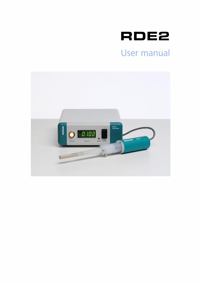
RDE2 User manual

DECLARATION OF CONFORMITY We Metrohm Autolab B.V.
Utrecht The Netherlands
Certify that the product
AUTOLAB RDE
is in conformity with EC Directives 89/336/EEC and 73/23/EWG.
Standards used: EMC: EN 61326-1 Safety: EN 61010
Description of the instrument:
Rotating Disk Electrode (RDE) with a rotating liquid Hg contact, including a system for controlling rotational speed of a dedicated DC motor.
Utrecht,
J.J.M. Coenen, QC Manager
Metrohm Autolab B.V. at Utrecht will not accept any liability for damages caused directly or indirectly by connecting this instrument to devices, which do not meet relevant safety standards. The AUTOLAB RDE was developed as a laboratory research instrument. Metrohm Autolab B.V. cannot under any circumstance be held responsible for the results of the use of the RDE.
Please read this manual carefully before using the RDE system.
This manual describes the RDE system. The sections deal with appearance and use of the RDE and contain necessary information regarding operation and installation. Not following these instructions when using the RDE may cause
The next sections deal with appearance and use of the module and contain necessary information regarding operation and installation.
SAFETY PRACTICES
General
The following safety practices are intended to ensure safe operation of the equipment. Not following these instructions when using the RDE motor controller may cause unsafe operation.
Metrohm Autolab is not liable for any damage caused by not complying with the following instructions.
Electrical Hazards
• There are no user-serviceable parts inside. Servicing should only be done by qualified personnel.
• Removal of panels exposes to potentially dangerous voltages. Always disconnect the controller from all power sources before removing protective panels.
• Replace blown fuses only with size and rating stipulated on or near the fuse panel holder and in the manual.
• Replace or repair faulty or frayed insulation on power cords and motor cable.
• Replace motor cable only with the original spare part. • When replacing power cord, use only approved type and conform local
regulations. • Be sure power cords are plugged into the correct voltage source and
always use a wall outlet with protective earth. • Check all connected equipment for proper grounding. Do not move the
motor controller with power cords connected.
General Precautions
• Do not place the controller on an unstable surface. • Do not expose the controller to damp or wet conditions.
WARNING: The RDE-2 mechanical unit contains a sealed mercury contact. In case of damage to the unit please handle with care. Do not throw the unit with ordinary waste.
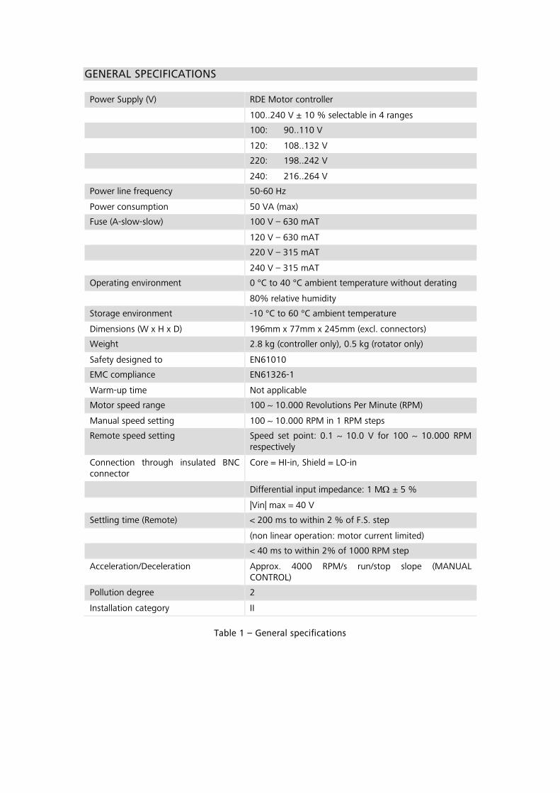
GENERAL SPECIFICATIONS
Power Supply (V) RDE Motor controller
100..240 V ± 10 % selectable in 4 ranges
100: 90..110 V
120: 108..132 V
220: 198..242 V
240: 216..264 V
Power line frequency 50-60 Hz
Power consumption 50 VA (max)
Fuse (A-slow-slow) 100 V – 630 mAT
120 V – 630 mAT
220 V – 315 mAT
240 V – 315 mAT
Operating environment 0 °C to 40 °C ambient temperature without derating
80% relative humidity
Storage environment -10 °C to 60 °C ambient temperature
Dimensions (W x H x D) 196mm x 77mm x 245mm (excl. connectors)
Weight 2.8 kg (controller only), 0.5 kg (rotator only)
Safety designed to EN61010
EMC compliance EN61326-1
Warm-up time Not applicable
Motor speed range 100 ~ 10.000 Revolutions Per Minute (RPM)
Manual speed setting 100 ~ 10.000 RPM in 1 RPM steps
Remote speed setting Speed set point: 0.1 ~ 10.0 V for 100 ~ 10.000 RPM respectively
Connection through insulated BNC connector
Core = HI-in, Shield = LO-in
Differential input impedance: 1 MΩ ± 5 %
|Vin| max = 40 V
Settling time (Remote) < 200 ms to within 2 % of F.S. step
(non linear operation: motor current limited)
< 40 ms to within 2% of 1000 RPM step
Acceleration/Deceleration Approx. 4000 RPM/s run/stop slope (MANUAL CONTROL)
Pollution degree 2
Installation category II
Table 1 – General specifications
Table of Contents
1 – Description .................................................................................................. 1 2 – Installation of the motor controller .............................................................. 1 3 – Powering the motor controller ..................................................................... 2 4 – Installation of the RDE rotating mechanical unit ........................................... 2
4.1 – Mounting the electrode ....................................................................... 2 4.2 – Connecting the RDE rotating mechanical unit to the motor controller . 4 4.3 – Connecting the RDE to the Autolab ..................................................... 4
5 – Controlling the RDE ..................................................................................... 6 5.1 – Manual control mode .......................................................................... 6
5.1.1 – Viewing and setting the speed the speed when the motor is off 7 5.1.2 – Viewing and setting the speed the speed when the motor is running .................................................................................................. 7
5.2 – Remote control mode (software controlled operation) ......................... 7 5.2.1 – Controlling the RDE with the Autolab ......................................... 8 5.2.2 – Software control in GPES/FRA .................................................... 8 5.2.3 – Software control in NOVA ........................................................ 10
6 – Cleaning and inspection ............................................................................. 11 7 – Changing and polishing the electrode tip ................................................... 12 8 – RDE storage ............................................................................................... 12 9 – Diagnostics ................................................................................................ 13 10 – Limited warranty ...................................................................................... 14
Autolab RDE User Manual
1 | P a g e
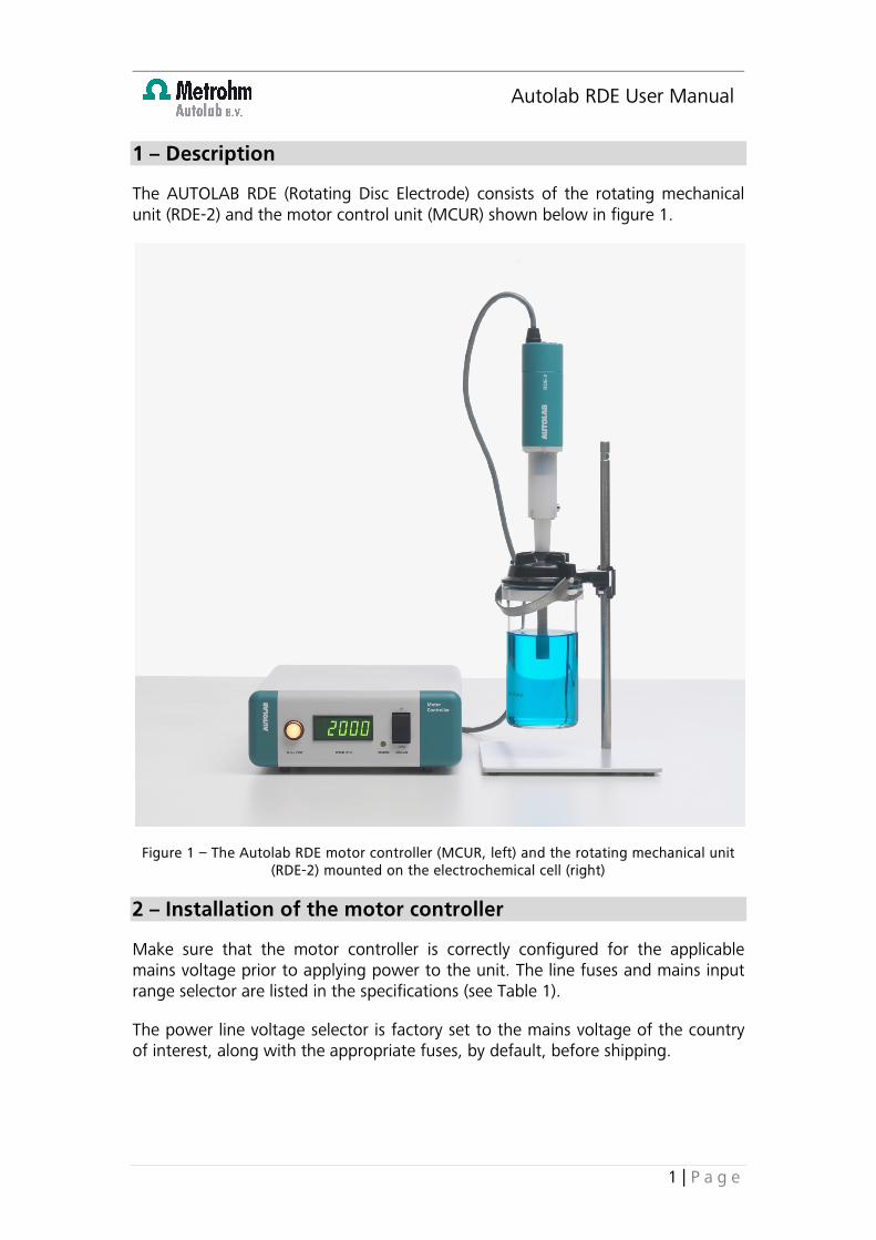
1 – Description
The AUTOLAB RDE (Rotating Disc Electrode) consists of the rotating mechanical unit (RDE-2) and the motor control unit (MCUR) shown below in figure 1.
Figure 1 – The Autolab RDE motor controller (MCUR, left) and the rotating mechanical unit (RDE-2) mounted on the electrochemical cell (right)
2 – Installation of the motor controller
Make sure that the motor controller is correctly configured for the applicable mains voltage prior to applying power to the unit. The line fuses and mains input range selector are listed in the specifications (see Table 1).
The power line voltage selector is factory set to the mains voltage of the country of interest, along with the appropriate fuses, by default, before shipping.
Autolab RDE User Manual
2 | P a g e
3 – Powering the motor controller
The mains power is applied to the unit by operating the mains switch on the rear panel, labelled: <POWER>. When the unit is powered, the numerical display on the front panel will be illuminated. The <SPEED> display on the front panel should read 0000 ± 4 RPM.
Note: the front panel display shows the real time rotation rate of the rotator. If the latter is not connected to the motor controller, the rotation rate will be 0 RPM.
4 – Installation of the RDE rotating mechanical unit
After unpacking, inspect the unit to make sure that there is no damage. The RDE contains a sealed rotating mercury contact. In case any damage is observed, contact your distributor or Metrohm Autolab immediately.
4.1 – Mounting the electrode
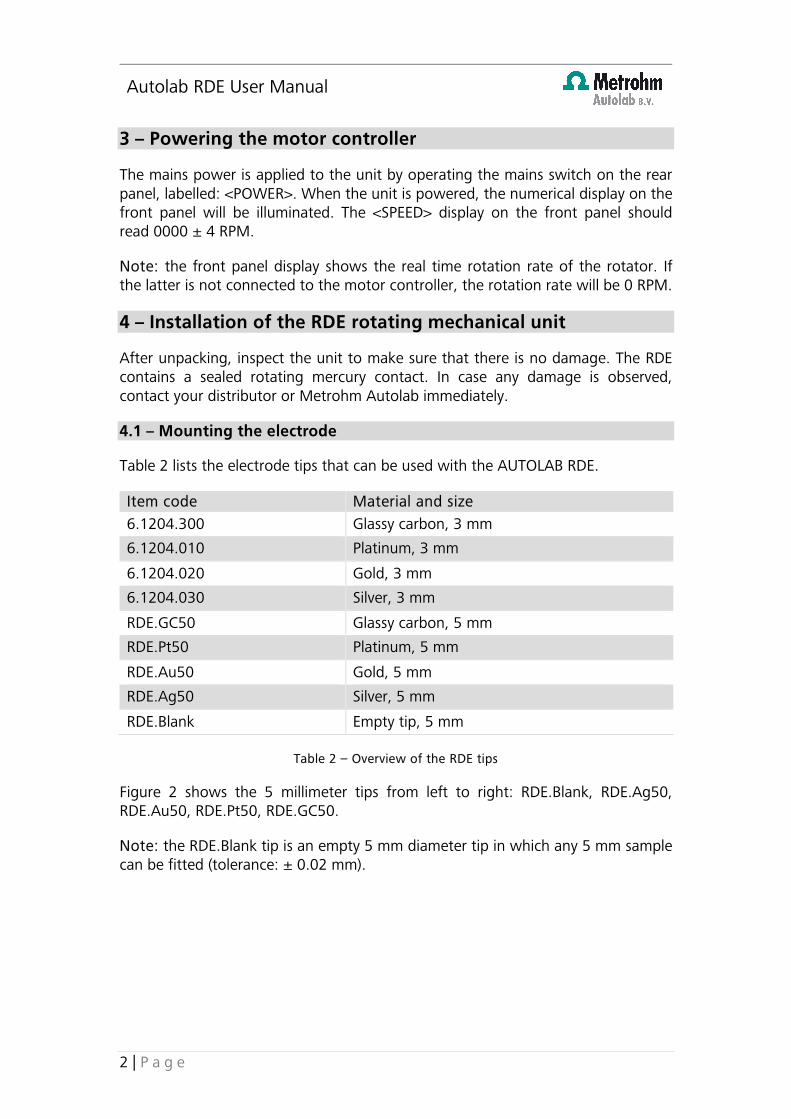
Table 2 lists the electrode tips that can be used with the AUTOLAB RDE.
Item code Material and size 6.1204.300 Glassy carbon, 3 mm
6.1204.010 Platinum, 3 mm
6.1204.020 Gold, 3 mm
6.1204.030 Silver, 3 mm
RDE.GC50 Glassy carbon, 5 mm
RDE.Pt50 Platinum, 5 mm
RDE.Au50 Gold, 5 mm
RDE.Ag50 Silver, 5 mm
RDE.Blank Empty tip, 5 mm
Table 2 – Overview of the RDE tips
Figure 2 shows the 5 millimeter tips from left to right: RDE.Blank, RDE.Ag50, RDE.Au50, RDE.Pt50, RDE.GC50.
Note: the RDE.Blank tip is an empty 5 mm diameter tip in which any 5 mm sample can be fitted (tolerance: ± 0.02 mm).
Autolab RDE User Manual
3 | P a g e
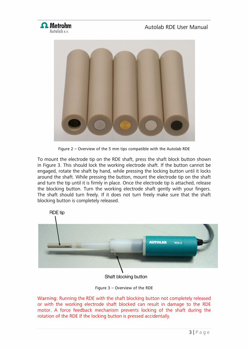
Figure 2 – Overview of the 5 mm tips compatible with the Autolab RDE
To mount the electrode tip on the RDE shaft, press the shaft block button shown in Figure 3. This should lock the working electrode shaft. If the button cannot be engaged, rotate the shaft by hand, while pressing the locking button until it locks around the shaft. While pressing the button, mount the electrode tip on the shaft and turn the tip until it is firmly in place. Once the electrode tip is attached, release the blocking button. Turn the working electrode shaft gently with your fingers. The shaft should turn freely. If it does not turn freely make sure that the shaft blocking button is completely released.
Figure 3 – Overview of the RDE
Warning: Running the RDE with the shaft blocking button not completely released or with the working electrode shaft blocked can result in damage to the RDE motor. A force feedback mechanism prevents locking of the shaft during the rotation of the RDE if the locking button is pressed accidentally.
RDE tip
Shaft blocking button
RDE tip
Shaft blocking button
Autolab RDE User Manual
4 | P a g e
4.2 – Connecting the RDE rotating mechanical unit to the motor controller
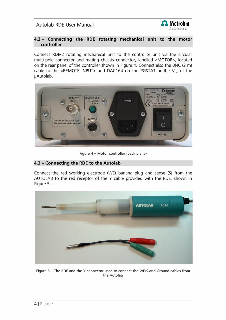
Connect RDE-2 rotating mechanical unit to the controller unit via the circular multi-pole connector and mating chassis connector, labelled <MOTOR>, located on the rear panel of the controller shown in Figure 4. Connect also the BNC (2 m) cable to the <REMOTE INPUT> and DAC164 on the PGSTAT or the Vout of the µAutolab.
Figure 4 – Motor controller (back plane)
4.3 – Connecting the RDE to the Autolab
Connect the red working electrode (WE) banana plug and sense (S) from the AUTOLAB to the red receptor of the Y cable provided with the RDE, shown in Figure 5.
Figure 5 – The RDE and the Y connector used to connect the WE/S and Ground cables from the Autolab
Autolab RDE User Manual
5 | P a g e
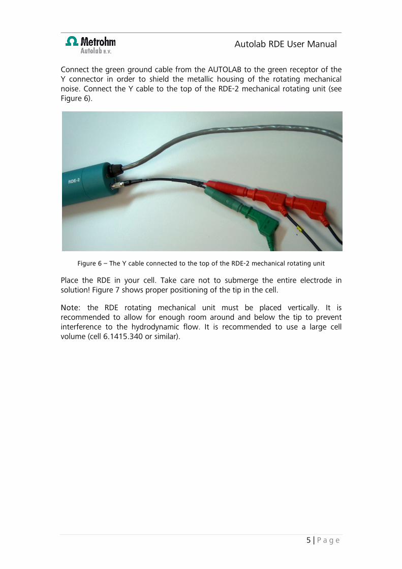
Connect the green ground cable from the AUTOLAB to the green receptor of the Y connector in order to shield the metallic housing of the rotating mechanical noise. Connect the Y cable to the top of the RDE-2 mechanical rotating unit (see Figure 6).
Figure 6 – The Y cable connected to the top of the RDE-2 mechanical rotating unit
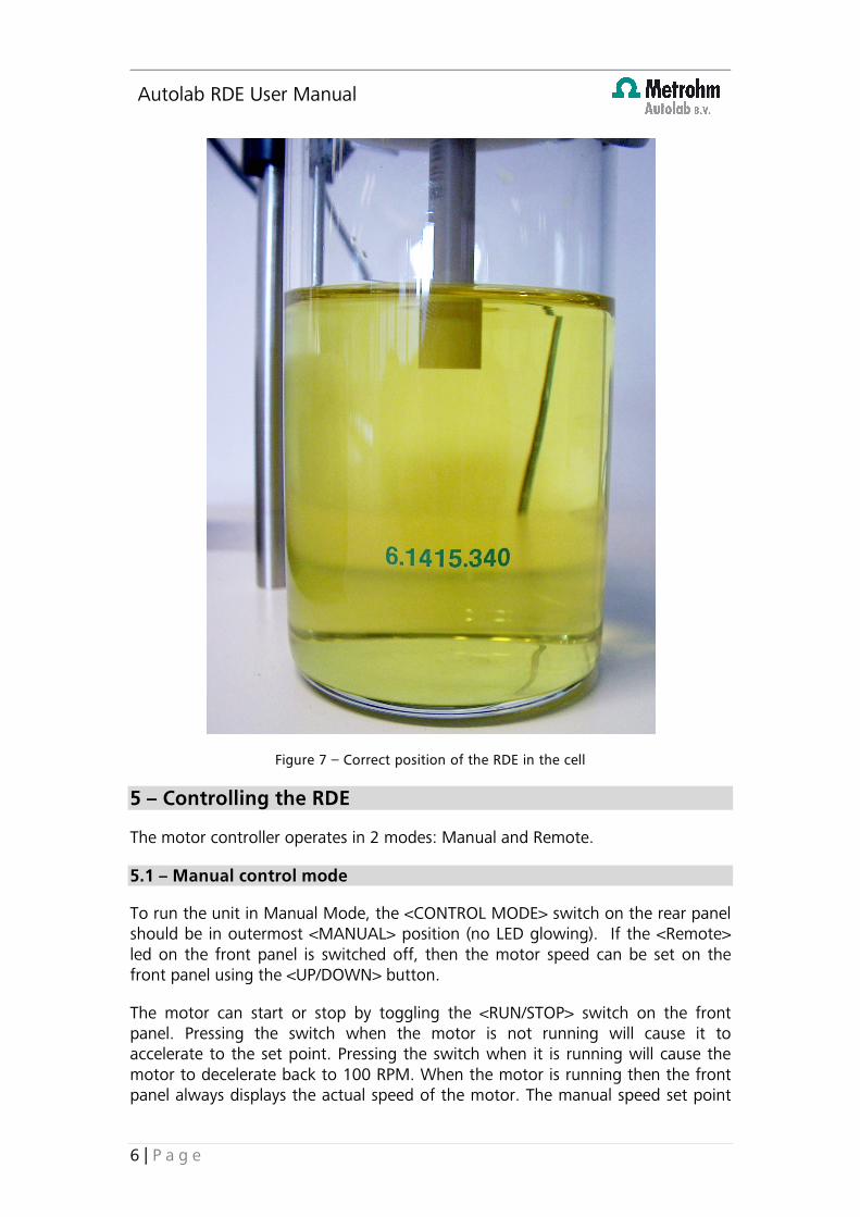
Place the RDE in your cell. Take care not to submerge the entire electrode in solution! Figure 7 shows proper positioning of the tip in the cell.
Note: the RDE rotating mechanical unit must be placed vertically. It is recommended to allow for enough room around and below the tip to prevent interference to the hydrodynamic flow. It is recommended to use a large cell volume (cell 6.1415.340 or similar).
Autolab RDE User Manual
6 | P a g e
Figure 7 – Correct position of the RDE in the cell
5 – Controlling the RDE
The motor controller operates in 2 modes: Manual and Remote.
5.1 – Manual control mode
To run the unit in Manual Mode, the <CONTROL MODE> switch on the rear panel should be in outermost <MANUAL> position (no LED glowing). If the <Remote> led on the front panel is switched off, then the motor speed can be set on the front panel using the <UP/DOWN> button.
The motor can start or stop by toggling the <RUN/STOP> switch on the front panel. Pressing the switch when the motor is not running will cause it to accelerate to the set point. Pressing the switch when it is running will cause the motor to decelerate back to 100 RPM. When the motor is running then the front panel always displays the actual speed of the motor. The manual speed set point
Autolab RDE User Manual
7 | P a g e
can be altered either when the motor is running or when the motor is stopped. Please note that the manual speed setpoint is volatile, so a previously entered setpoint before the unit was switched off the mains cannot be recalled.
5.1.1 – Viewing and setting the speed the speed when the motor is off
Immediately after power up the initial internal manual speed setpoint of the controller is set to 100 RPM for the RDE configuration and the motor is switched off <STOP>.
When the motor is not running, the speed set point can be viewed on the front panel display by pressing and releasing the <MANUAL> <UP> or <DOWN> front panel switch. The display will show the speed set point for approximately 3 seconds.
To change the speed set point continue holding the <UP> or <DOWN> switch. The speed setpoint will change in steps of 1 RPM. If you continue holding the <UP> or <DOWN> switch then every 4 s the step size will increase by a factor of 10 with a maximum step size of 1000 rpm. Once the new speed set point has been entered, the motor can be set to run by pressing the <RUN/STOP> switch. The motor will accelerate to the desired set point.
5.1.2 – Viewing and setting the speed the speed when the motor is running
When the motor is running, the actual rotation speed is displayed on the front panel. To increase or decrease the speed, press the front switch labelled <MANUAL> in either the <UP> or <DOWN> position. The speed will change in steps of 1 RPM. If you continue holding the <UP> or <DOWN> switch then every 4 s the step size will increase by a factor of 10 with a maximum step size of 1000 rpm.
5.2 – Remote control mode (software controlled operation)
The unit can be controlled remotely by providing a remote speed setpoint to the motor controller. To enable the unit to be controlled through the remote input, the switch on the rear panel, labelled <CONTROL MODE> should be set to <REMOTE> (in the <REMOTE> state, the <CONTROL MODE> switch on the rear panel and the <REMOTE> indicator light on the front panel are both illuminated).
The remote speed setpoint can be applied through the insulated BNC connector on the rear panel, labelled <REMOTE INPUT>. Core = HI-in, Shield = LO-in. The speed of the motor can be set by applying a voltage of +0.1 V (for 100 RPM) to +10.0 V (for 10.000 RPM) to this input.
Note: applying -2 V on the remote input sets the rotation rate of the RDE to 0 RPM. Please note that it is not possible to set the rotation rate to values between 100 and 0 RPM.
Autolab RDE User Manual
8 | P a g e
Warning: To exclude any deviations in remote speed set points due to the load impedance of the controller’s remote input please respect the controller’s input impedance of 1MΩ ± 5%.
5.2.1 – Controlling the RDE with the Autolab
Connect the DAC164 channel 1 or 2 in the front of the AUTOLAB (or the Vout of the µAutolab) to the BNC connector on the rear panel of the motor controller, labelled <REMOTE INPUT>.
5.2.2 – Software control in GPES/FRA
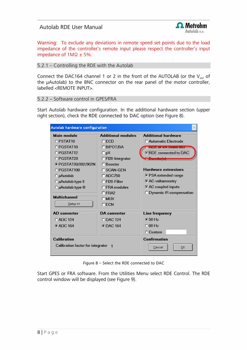
Start Autolab hardware configuration. In the additional hardware section (upper right section), check the RDE connected to DAC option (see Figure 8).
Figure 8 – Select the RDE connected to DAC
Start GPES or FRA software. From the Utilities Menu select RDE Control. The RDE control window will be displayed (see Figure 9).
Autolab RDE User Manual
9 | P a g e
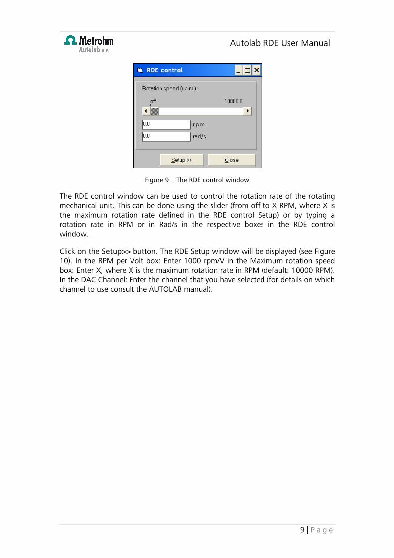
Figure 9 – The RDE control window
The RDE control window can be used to control the rotation rate of the rotating mechanical unit. This can be done using the slider (from off to X RPM, where X is the maximum rotation rate defined in the RDE control Setup) or by typing a rotation rate in RPM or in Rad/s in the respective boxes in the RDE control window.
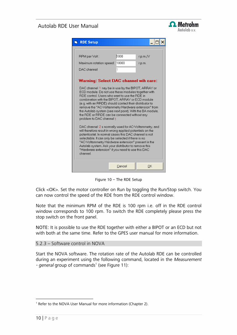
Click on the Setup>> button. The RDE Setup window will be displayed (see Figure 10). In the RPM per Volt box: Enter 1000 rpm/V in the Maximum rotation speed box: Enter X, where X is the maximum rotation rate in RPM (default: 10000 RPM). In the DAC Channel: Enter the channel that you have selected (for details on which channel to use consult the AUTOLAB manual).
Autolab RDE User Manual
10 | P a g e
Figure 10 – The RDE Setup
Click <OK>. Set the motor controller on Run by toggling the Run/Stop switch. You can now control the speed of the RDE from the RDE control window.
Note that the minimum RPM of the RDE is 100 rpm i.e. off in the RDE control window corresponds to 100 rpm. To switch the RDE completely please press the stop switch on the front panel.
NOTE: It is possible to use the RDE together with either a BIPOT or an ECD but not with both at the same time. Refer to the GPES user manual for more information.
5.2.3 – Software control in NOVA
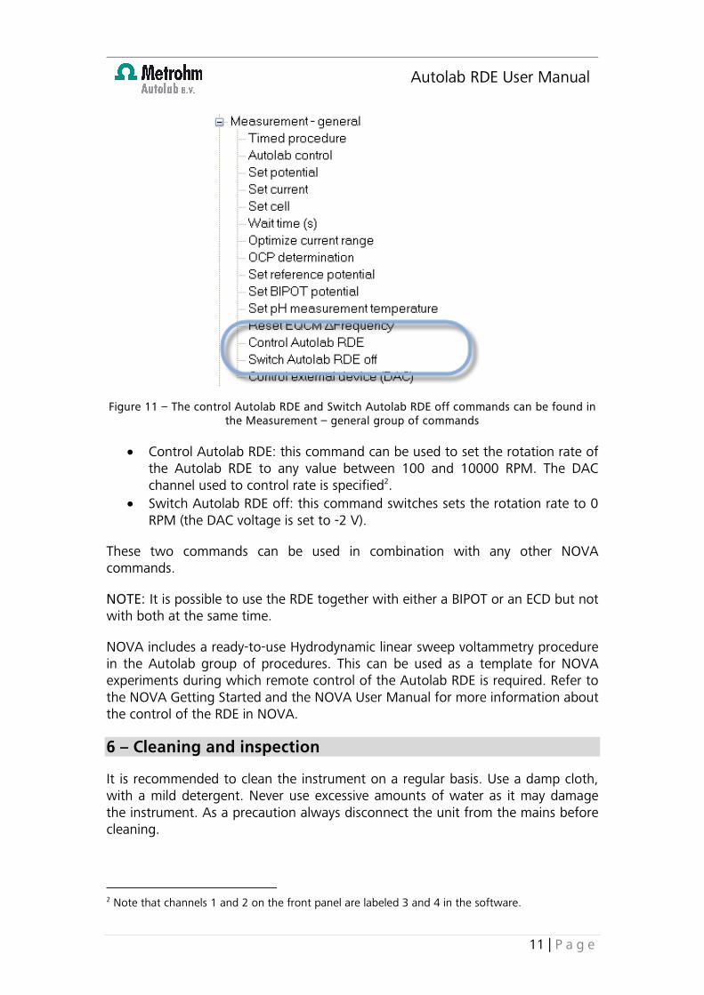
Start the NOVA software. The rotation rate of the Autolab RDE can be controlled during an experiment using the following command, located in the Measurement - general group of commands1 (see Figure 11):
1 Refer to the NOVA User Manual for more information (Chapter 2).
Autolab RDE User Manual
11 | P a g e
Figure 11 – The control Autolab RDE and Switch Autolab RDE off commands can be found in the Measurement – general group of commands
• Control Autolab RDE: this command can be used to set the rotation rate of the Autolab RDE to any value between 100 and 10000 RPM. The DAC channel used to control rate is specified2.
• Switch Autolab RDE off: this command switches sets the rotation rate to 0 RPM (the DAC voltage is set to -2 V).
These two commands can be used in combination with any other NOVA commands.
NOTE: It is possible to use the RDE together with either a BIPOT or an ECD but not with both at the same time.
NOVA includes a ready-to-use Hydrodynamic linear sweep voltammetry procedure in the Autolab group of procedures. This can be used as a template for NOVA experiments during which remote control of the Autolab RDE is required. Refer to the NOVA Getting Started and the NOVA User Manual for more information about the control of the RDE in NOVA.
6 – Cleaning and inspection
It is recommended to clean the instrument on a regular basis. Use a damp cloth, with a mild detergent. Never use excessive amounts of water as it may damage the instrument. As a precaution always disconnect the unit from the mains before cleaning.
2 Note that channels 1 and 2 on the front panel are labeled 3 and 4 in the software.
Autolab RDE User Manual
12 | P a g e
Always perform an inspection of the instrument and all its connecting cables before use. If you find any cable with damaged insulation or other irregularities, stop using the instrument until it has been repaired. Damaged equipment or damaged cables may be hazardous!
7 – Changing and polishing the electrode tip
It is recommended first to remove the electrode tip from the rotating mechanical unit prior to cleaning and polishing the electrode tips used in your chemical experiment. Please always follow the manufacturer’s suggestions for polishing your particular electrode.
To remove the electrode tip from the rotating mechanical unit – first turn off the rotator. Always remember to press the <RUN/STOP> button on the motor controller unit and be sure the LED is not illuminated. <STOP> the rotation completely otherwise damage may result to the shaft blocking button and maybe even the Hg contact itself.
Second, remove the rotator from the electrochemical cell being sure to rinse off all solution material/salts. Dry both the electrode and the axis carefully with a soft lab tissue. Block the shaft of the rotating mechanical unit by pressing the blocking button to lock the RDE shaft and very gently, by hand, untwist the RDE electrode! Exert no force beyond that of your own fingers.
WARNING: If the electrode cannot be removed by hand using the axis locking button, the unit must be returned to Metrohm Autolab for repair! Using excessive force on the axis may break the Hg contact. If the Hg contact leaks you will have trouble with future measurements.
8 – RDE storage
In experimental conditions take care not to expose the axis to a corrosive environment for long periods of time. Between samples always rinse the rotating tip and dry thoroughly before continuing analyses.
Do not store the RDE upside down. Do not store the RDE with an electrode attached. Always rinse the RDE electrodes and rotation axis with demineralised water, store dry and separately before leaving for prolonged periods.
To avoid damage to the unit please handle with care.
WARNING: The RDE rotating mechanical unit contains a sealed mercury contact. Do not throw the unit with ordinary waste. This mercury seal may break if the unit is dropped or used with excessive force. Breaking the mercury seal will result in irreparable damage and the unit will need to be replaced.
Autolab RDE User Manual
13 | P a g e
Do not for any reason attempt to open the unit. There are no user serviceable parts. Failure to conform to user specifications described above may result in the void of any warranty claims.
9 – Diagnostics
Problem: The controller does not seem to power up, after toggling the power switch (front speed display does not show any readings).
Cause The controller is not powered Solution Check mains connection Check fuses
Problem: The <RUN/STOP> switch illumination keeps blinking and the motor cannot be set to <RUN>, although the controller seems to power up normally and the set point can be set using the front panel controls.
Cause The motor assembly is not or not properly connected to the controller Solution Check the motor connection cable to be sure the RDE rotator is
attached
Problem: The speed display does not show motor speeds under ~100 RPM, although a set point under 100 RPM is applied to the remote input.
Cause To meet the controller’s accuracy specification, motor speeds fewer than 100 RPM are not allowed. Therefore the remote set point is internally limited to ~100 RPM on the low end of the speed range
Solution Do not attempt to set the speeds to values under 100 RPM
Problem: The motor cannot be operated at the maximum speed of 10.000 ± 4 RPM, while in <MANUAL> control mode.
Cause 1 The mains voltage probably does not meet the lower limit specification (according to the line setting)
Solution Check line setting (see Installation guide)
Cause 2 The motor assembly is blocked or obstructed in any way (under normal operating conditions the motor requires to run freely, without any additional mechanical loads, except for some inertia of the RDE electrode tip and some work due to viscous friction of the air or electrolyte respectively)
Solution Make sure the motor is able to run freely by ensuring that the motor block pin is released
Problem: The rotation speed cannot be set to zero in “remote mode” with the software (GPES/FRA).
Autolab RDE User Manual
14 | P a g e
Solution Upgrade software to release 4.9.6 (or higher)
10 – Limited warranty
The Autolab RDE rotating mechanical unit as well as the Motor controller do not contain any user serviceable parts. Any attempt to open or disassemble the rotator and/or the motor controller will void any warranty. Please contact your Autolab distribitor or Metrohm Autolab if the rotator or the motor controller.
The Autolab RDE rotating mechanical unit is intended to be used with Metrohm Autolab certified electrode tips only (see Table 2). Using uncertified tips will immediately void any warranty. Please contact Metrohm Autolab for custom electrode tips requests ([email protected]).

7/2011
Kanaalweg 29/G 3526 KM Utrecht The Netherlands