Embed Size (px)
Citation preview
Publication T1-702, Rev. 1 Dated: January 22, 2001
INSTALLATION AND OPERATING MANUAL
MODELS: T100-B, T100-D, T100-F, T100-P
TURBOTWIN Engine Air Starters
AN 95-414 From Tech Development Inc 6800 Poe Ave. �Dayton OH 45414 Tel: (937) 898-9600 �Fax: (937) 898-8431
TDI TURBOTWIN FROM TECH DEVELOPMENT INC
TABLE OF CONTENTS
SECTION SUBJECT PAGE
1.0 GENERAL INFORMATION 2 1.1 DESCRIPTION 2 1.2 PRODUCT IDENTIFICATION 2 1.3 PERFORMANCE 3 2.0 ORIENTATION OF THE STARTER 3 2.1 GENERAL 3 3.0 INSTALLING THE STARTER 3 3.1 SUPPLY LINE INSTALLATION 3 3.2 NLET PRESSURE PORT 4 3.3 EXHAUST PIPING 4 3.4 NATURAL GAS INSTALLATION 4 3.5 PIPING SYSTEM 4 3.6 BACKLASH 5 4.0 STARTER OPERATION 5 4.1 BASIC OPERATION 6 4.2 AUTOMATED START PANEL 6 5.0 PREVENTIVE MAINTENANCE 6 6.0 TROUBLE SHOOTING GUIDE 7 7.0 TURBOTWIN WARRANTY 8 LIST OF FIGURES 1. TURBOTWIN PART NUMBER LISTING 2. MODEL T112B/T121B INSTALLATION DRAWING 3. MODEL T106F/T112F INSTALLATION DRAWING 4. MODEL T112D/T121D INSTALLATION DRAWING (STD MESH) 5. MODEL T112D/T121D INSTALLATION DRAWING
Publication T1-702, Rev 1 Issued January 22, 2001 1
TDI TURBOTWIN FROM TECH DEVELOPMENT INC 1.0 GENERAL INFORMATION This manual provides instructions for the installation and operation of the TDI T100 TURBOTWIN Starters (Series: B,D,F,P). If there are questions not answered in this manual, please contact your TDI TURBOTWIN distributor or dealer for assistance. The T100 TURBOTWIN models are turbine driven starters with an inertially engaged starter drive. Depending on the starter model and engine installation, the TURBOTWIN starters have applications ranging from 1200 CID (20 Liters) on diesel engines and up to 15000 CID (250 Liters) on gas engines. The TURBOTWIN models are suited to operate within a wide range of inlet pressures and ambient temperatures. The engine size and parasitic loading will determine the exact minimum pressure that will assure reliable starting. The T100 TURBOTWIN starters are designed for operation with compressed air or natural gas; materials used are compatible with “sour” natural gas and marine environments. Small amounts of foreign matter or liquid in the air stream will not adversely affect TURBOTWIN starters. As with all other TDI starters, no lubrication is required in the air supply. Please review the rest of this manual before installing the T100 TURBOTWIN series air starter. WARNINGS, CAUTIONS AND NOTES Certain types of information are highlighted in this manual for your attention:
WARNING - used where injury to personnel or damage to the equipment is likely.
CAUTION - used where there is the possibility of damage to the equipment.
NOTE - used to point out special interest information.
NOTE Throughout this manual, the term “air” is used to designate the starter drive medium. Unless other wise stated, air “ means either compressed air or natural gas. 1.1 DESCRIPTION All models feature three basic subassemblies: a unique two stage turbine motor section, a planetary gearbox section and an inertia drive assembly. The two stage motor section features greater stall torque than a single stage turbine plus aerodynamic speed control.
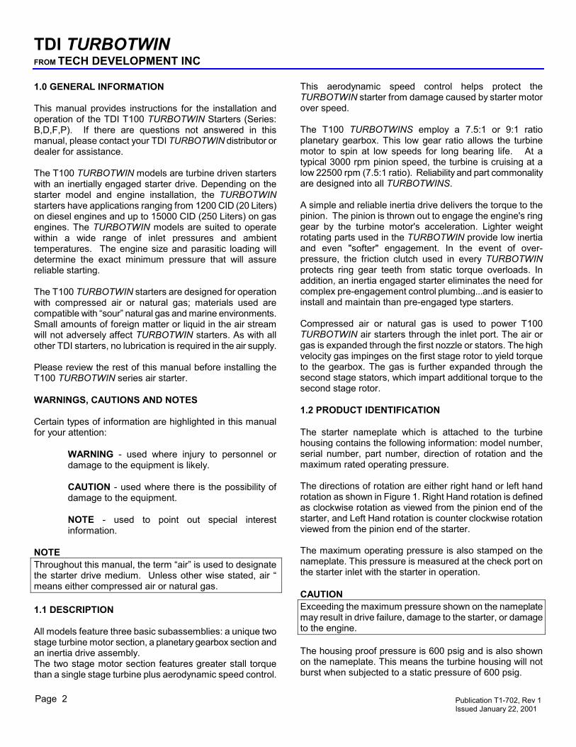
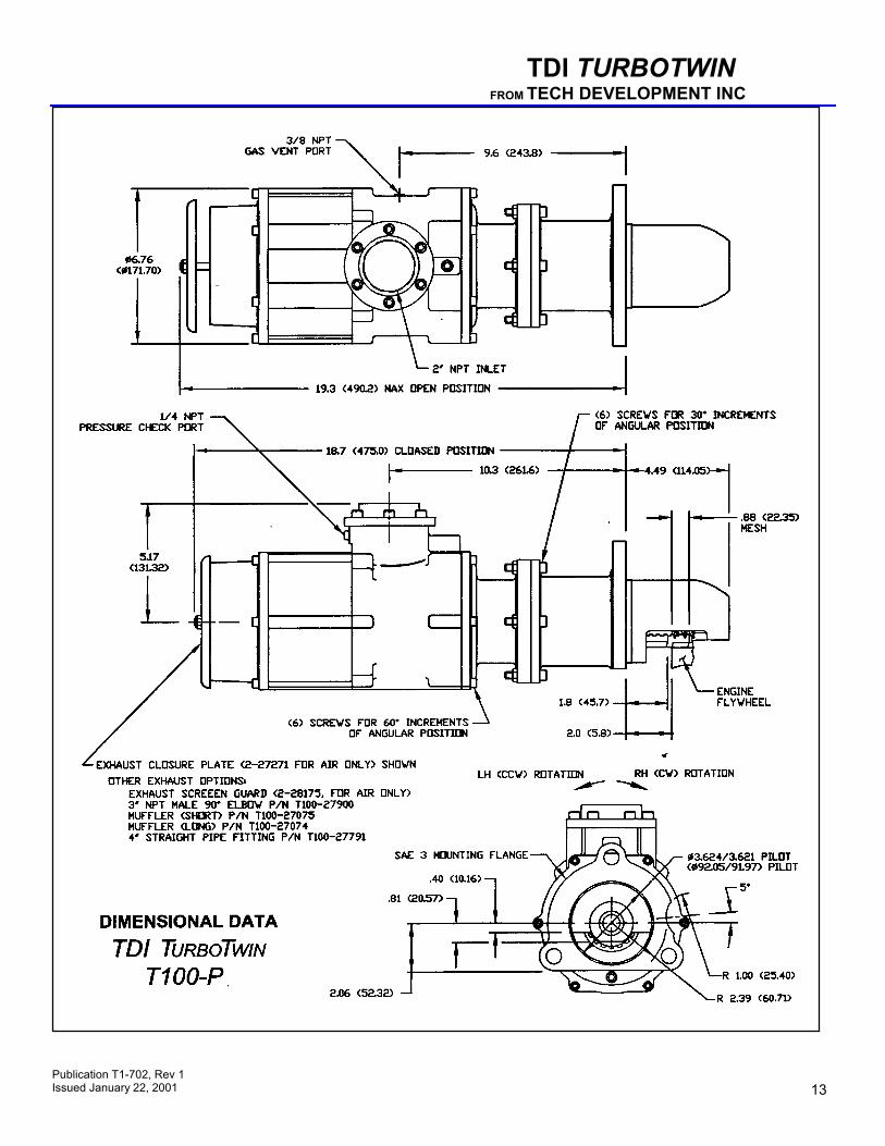
This aerodynamic speed control helps protect the TURBOTWIN starter from damage caused by starter motor over speed. The T100 TURBOTWINS employ a 7.5:1 or 9:1 ratio planetary gearbox. This low gear ratio allows the turbine motor to spin at low speeds for long bearing life. At a typical 3000 rpm pinion speed, the turbine is cruising at a low 22500 rpm (7.5:1 ratio). Reliability and part commonality are designed into all TURBOTWINS. A simple and reliable inertia drive delivers the torque to the pinion. The pinion is thrown out to engage the engine's ring gear by the turbine motor's acceleration. Lighter weight rotating parts used in the TURBOTWIN provide low inertia and even "softer" engagement. In the event of over-pressure, the friction clutch used in every TURBOTWIN protects ring gear teeth from static torque overloads. In addition, an inertia engaged starter eliminates the need for complex pre-engagement control plumbing...and is easier to install and maintain than pre-engaged type starters. Compressed air or natural gas is used to power T100 TURBOTWIN air starters through the inlet port. The air or gas is expanded through the first nozzle or stators. The high velocity gas impinges on the first stage rotor to yield torque to the gearbox. The gas is further expanded through the second stage stators, which impart additional torque to the second stage rotor. 1.2 PRODUCT IDENTIFICATION The starter nameplate which is attached to the turbine housing contains the following information: model number, serial number, part number, direction of rotation and the maximum rated operating pressure. The directions of rotation are either right hand or left hand rotation as shown in Figure 1. Right Hand rotation is defined as clockwise rotation as viewed from the pinion end of the starter, and Left Hand rotation is counter clockwise rotation viewed from the pinion end of the starter. The maximum operating pressure is also stamped on the nameplate. This pressure is measured at the check port on the starter inlet with the starter in operation. CAUTION Exceeding the maximum pressure shown on the nameplate may result in drive failure, damage to the starter, or damage to the engine. The housing proof pressure is 600 psig and is also shown on the nameplate. This means the turbine housing will not burst when subjected to a static pressure of 600 psig.
Publication T1-702, Rev 1 Issued January 22, 2001 Page 2
TDI TURBOTWIN FROM TECH DEVELOPMENT INC
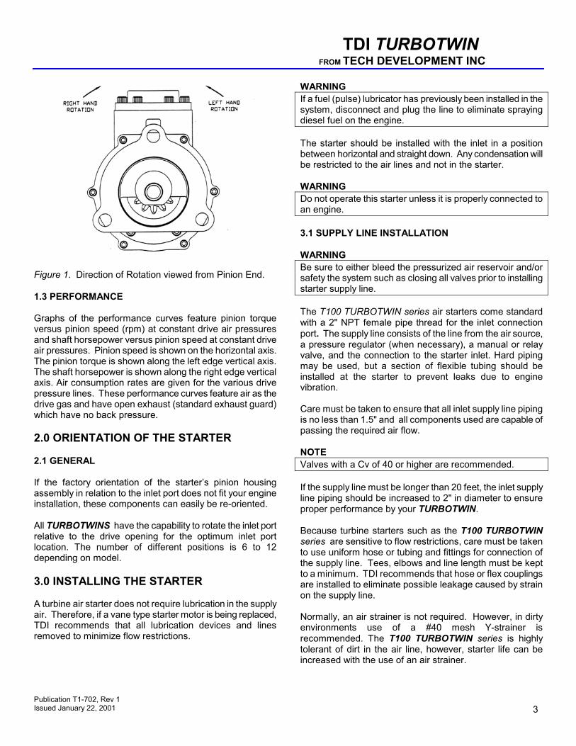
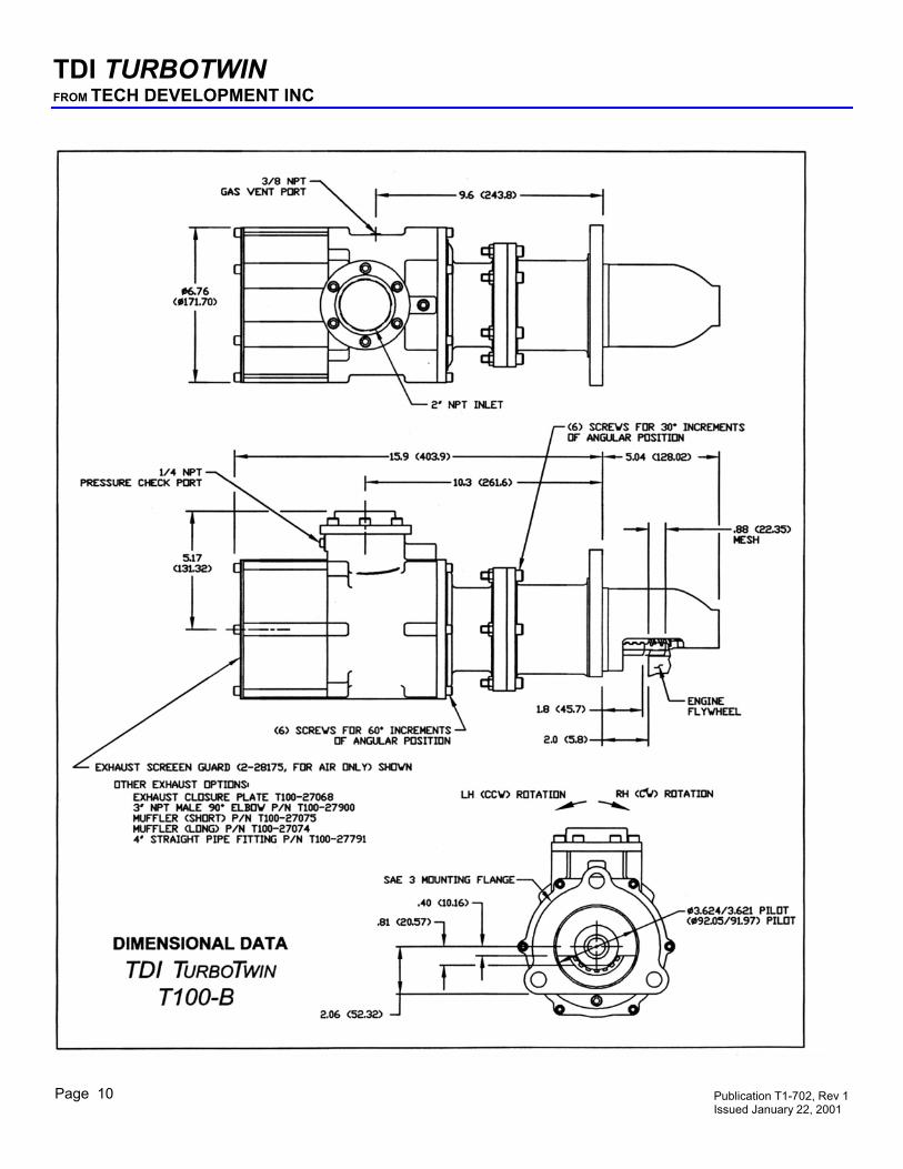
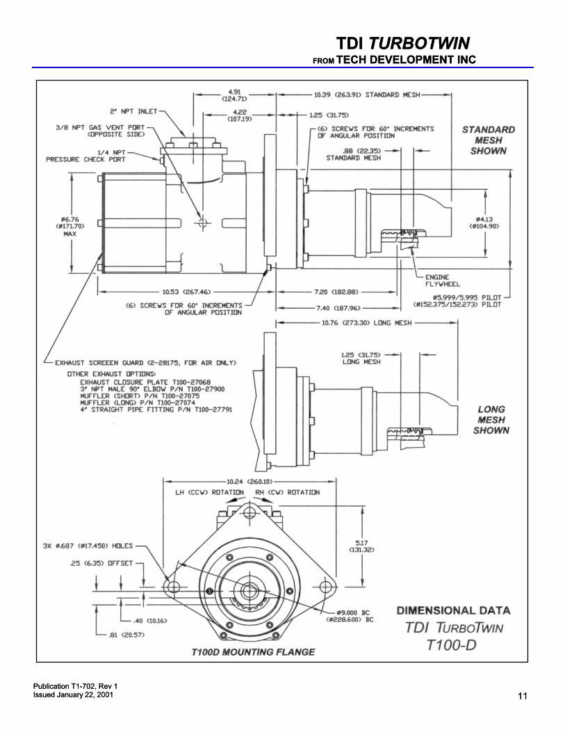
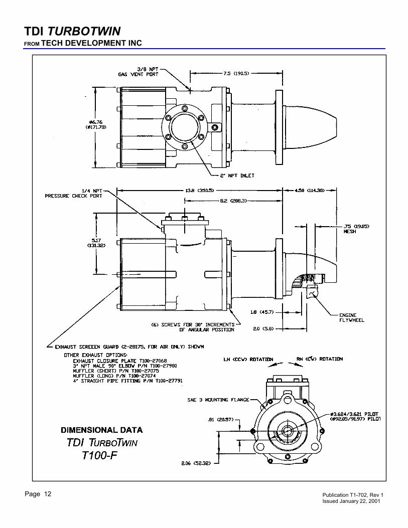
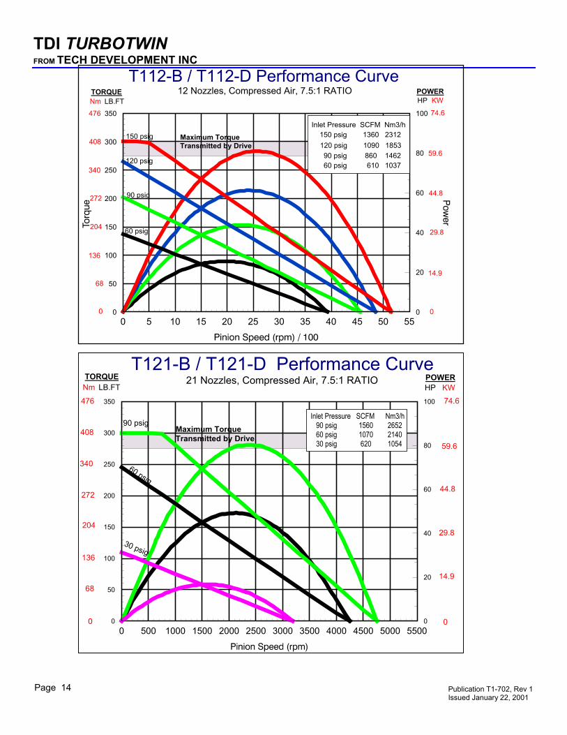
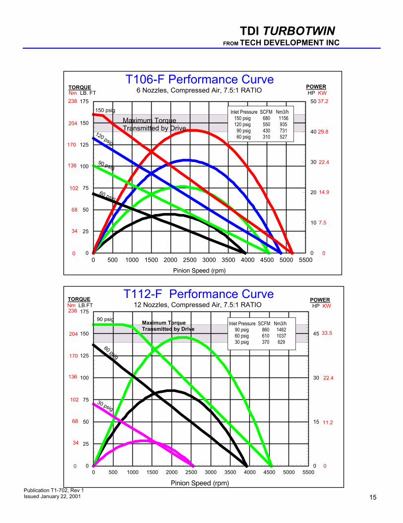
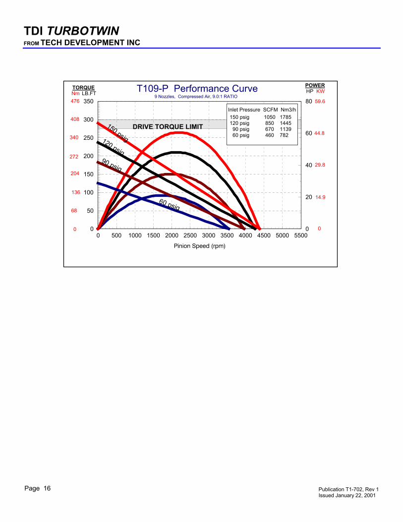
Figure 1. Direction of Rotation viewed from Pinion End. 1.3 PERFORMANCE Graphs of the performance curves feature pinion torque versus pinion speed (rpm) at constant drive air pressures and shaft horsepower versus pinion speed at constant drive air pressures. Pinion speed is shown on the horizontal axis. The pinion torque is shown along the left edge vertical axis. The shaft horsepower is shown along the right edge vertical axis. Air consumption rates are given for the various drive pressure lines. These performance curves feature air as the drive gas and have open exhaust (standard exhaust guard) which have no back pressure. 2.0 ORIENTATION OF THE STARTER 2.1 GENERAL If the factory orientation of the starter’s pinion housing assembly in relation to the inlet port does not fit your engine installation, these components can easily be re-oriented. All TURBOTWINS have the capability to rotate the inlet port relative to the drive opening for the optimum inlet port location. The number of different positions is 6 to 12 depending on model. 3.0 INSTALLING THE STARTER A turbine air starter does not require lubrication in the supply air. Therefore, if a vane type starter motor is being replaced, TDI recommends that all lubrication devices and lines removed to minimize flow restrictions.
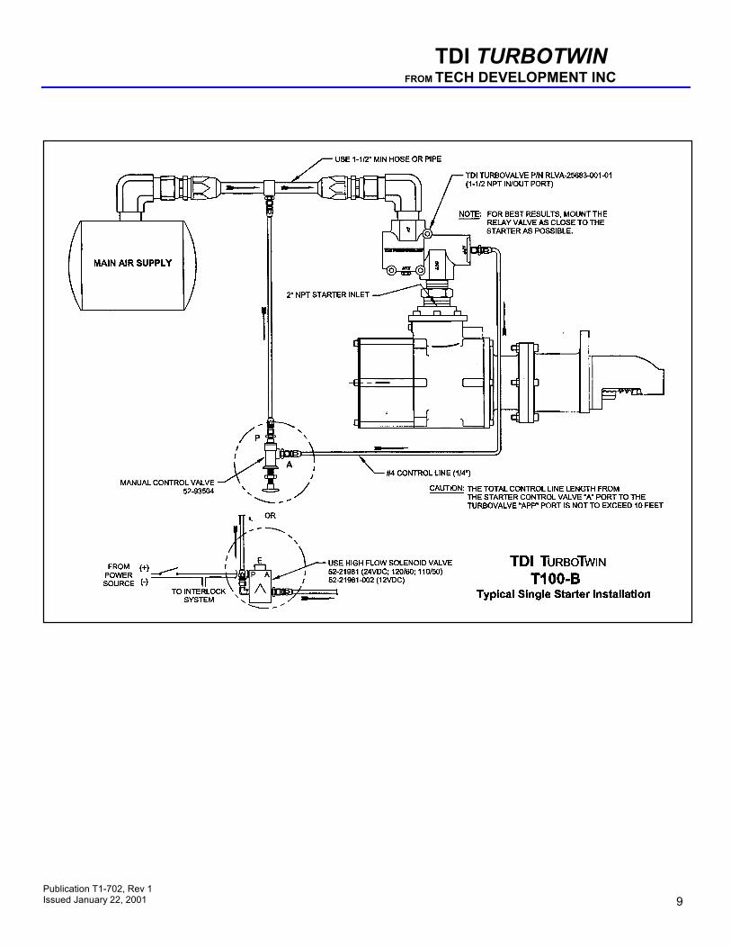
WARNING If a fuel (pulse) lubricator has previously been installed in the system, disconnect and plug the line to eliminate spraying diesel fuel on the engine. The starter should be installed with the inlet in a position between horizontal and straight down. Any condensation will be restricted to the air lines and not in the starter. WARNING Do not operate this starter unless it is properly connected to an engine. 3.1 SUPPLY LINE INSTALLATION WARNING Be sure to either bleed the pressurized air reservoir and/or safety the system such as closing all valves prior to installing starter supply line. The T100 TURBOTWIN series air starters come standard with a 2" NPT female pipe thread for the inlet connection port. The supply line consists of the line from the air source, a pressure regulator (when necessary), a manual or relay valve, and the connection to the starter inlet. Hard piping may be used, but a section of flexible tubing should be installed at the starter to prevent leaks due to engine vibration. Care must be taken to ensure that all inlet supply line piping is no less than 1.5" and all components used are capable of passing the required air flow. NOTE Valves with a Cv of 40 or higher are recommended. If the supply line must be longer than 20 feet, the inlet supply line piping should be increased to 2" in diameter to ensure proper performance by your TURBOTWIN. Because turbine starters such as the T100 TURBOTWIN series are sensitive to flow restrictions, care must be taken to use uniform hose or tubing and fittings for connection of the supply line. Tees, elbows and line length must be kept to a minimum. TDI recommends that hose or flex couplings are installed to eliminate possible leakage caused by strain on the supply line. Normally, an air strainer is not required. However, in dirty environments use of a #40 mesh Y-strainer is recommended. The T100 TURBOTWIN series is highly tolerant of dirt in the air line, however, starter life can be increased with the use of an air strainer.
Publication T1-702, Rev 1 Issued January 22, 2001 3
TDI TURBOTWIN FROM TECH DEVELOPMENT INC A pressure regulator is required when the air supply pressure is great enough to exceed the starter operating pressure (at the inlet port) and/or the maximum torque. A manual ball valve may be used to admit drive air/gas to the starter. The manual valve should be located in a safe position away from the engine. A preferred valve is pilot-operated, which can be pneumatically or electrically actuated. The valve should be located close to or even on the starter inlet for best performance. Pneumatic or electrical control lines may be routed virtually anywhere for the customer's preferred operating station. This type of valve actuates from a fully closed to a fully open position very rapidly. TDI offers a variety of relay valves such as P/N RLVA-25683-001-2-01, which is a 1-1/2" port, pneumatically actuated valve. The supply line should be dry-fitted for proper alignment /location prior to final assembly. All pipe threaded joints should be sealed with Loctite Pipe Thread Sealant (TDI P/N 9-94085) or equivalent for leak tight joints prior to final assembly. Be sure to tighten all joints to proper torque after final assembly. CAUTION In cold weather climates, care should be taken while designing your installation to prevent condensation from developing in the starter system. In systems with a regulator valve or relay valve, there is the possibility of freeze-ups. A tee connection with a quick disconnect can be added to the inlet. This will allow an external air source to be used to accomplish a “blow start” if the system freezes. Once the engine has been started, the other system components may be thawed. CAUTION On new installations, it is strongly recommended to blow out the supply line with air to remove possible dirt and welding slag prior to final connection to the TURBOTWIN starter. Be sure to secure the free end of the supply line prior to blowing out the line. 3.2 INLET PRESSURE PORT A 1/4" NPT port is located on the air inlet. This port may be used to check the supply pressure at the starter when the starter is operating. Remove the 1/4" NPT pipe plug and save for later use. Install a 1/4" minimum size tubing to the port. Route the tubing away from the starter to a safe location away from the engine. Install a pressure gauge on the tubing. This pressure monitoring line/gauge may be permanently installed. Use Loctite Pipe Thread Sealant or equivalent. Alternately, a pressure transducer may be
installed at the pressure check port and electrical lines routed to a digital display at the operator's station. This pressure port is invaluable in diagnosing air starter and/or installation problems. 3.3 EXHAUST PIPING The turbine exhaust may be plumbed away from the starter area. All starters using natural gas must be piped according to industry codes and local regulations. The performance of a turbine starter will be decreased because of back pressure when smaller than recommended exhaust piping is installed. If back pressure hampers starter performance, compensation can be made by increasing the supply pressure. Consult your TDI distributor for advice. Exhaust piping should be routed downward to help prevent any accumulation of condensation in the starter motor. If the overhung section of the starter is not otherwise supported, TDI recommends supporting the exhaust piping with a suitable bracket(s). Exhaust piping should be routed downward to help prevent any accumulation of condensate in the starter motor. 3.4 NATURAL GAS INSTALLATION The installation of the starter using natural gas is similar to the air installation except all fittings, piping, valves and regulators must be compatible with natural gas. Proper control of natural gas is a major consideration when used in the starter system. All starters using natural gas must pipe the exhaust according to industry codes and local regulations. There is a natural gas vent port in the turbine housing that is plugged for compressed air use. This vent is used to remove any natural gas that could leak past the primary turbine shaft seal. Remove this 3/8"NPT plug and install a line to carry gas away from the starter area. WARNING Do not connect the turbine housing vent line to the turbine exhaust line. Exhaust gas can pressurize the housing. 3.5 PIPING SYSTEM Only type approved metallic hose assemblies are approved in permanently pressurized compressed air lines of starters. Non-metallic hose assemblies are allowed only in case the piping system will be emptied after the starting procedure.
Publication T1-702, Rev 1 Issued January 22, 2001 Page 4
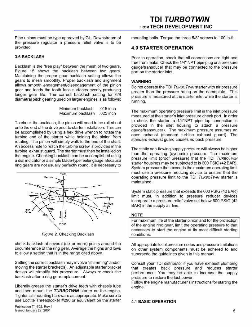
TDI TURBOTWIN FROM TECH DEVELOPMENT INC Pipe unions must be type approved by GL. Downstream of the pressure regulator a pressure relief valve is to be provided. 3.6 BACKLASH Backlash is the "free play" between the mesh of two gears. Figure 15 shows the backlash between two gears. Maintaining the proper gear backlash setting allows the gears to mesh smoothly. Proper backlash and alignment allows smooth engagement/disengagement of the pinion gear and loads the tooth face surfaces evenly producing longer gear life. The correct backlash setting for 6/8 diametral pitch gearing used on larger engines is as follows:
Minimum backlash .015 inch Maximum backlash .025 inch
To check the backlash, the pinion will need to be rolled out onto the end of the drive prior to starter installation. This can be accomplished by using a hex drive wrench to rotate the turbine end of the starter while holding the pinion from rotating. The pinion will simply walk to the end of the shaft. An access hole to reach the turbine screw is provided in the turbine exhaust guard. The starter must then be installed on the engine. Checking backlash can be accomplished using a dial indicator or a simple blade-type feeler gauge. Because ring gears are not usually perfectly round, it is necessary to
Figure 2. Checking Backlash
check backlash at several (six or more) points around the circumference of the ring gear. Average the highs and lows to allow a setting that is in the range cited above. Setting the correct backlash may involve "shimming" and/or moving the starter bracket(s). An adjustable starter bracket design will simplify this procedure. Always re-check the backlash after a ring gear replacement. Liberally grease the starter’s drive teeth with chassis lube and then mount the TURBOTWIN starter on the engine. Tighten all mounting hardware as appropriate. Make sure to use Loctite Threadlocker #290 or equivalent on the starter
mounting bolts. Torque the three 5/8" screws to 100 lb-ft. 4.0 STARTER OPERATION Prior to operation, check that all connections are tight and free from leaks. Check the 1/4" NPT pipe plug or a pressure gauge/transducer that may be connected to the pressure port on the starter inlet. WARNING Do not operate the TDI TURBOTWIN starter with air pressure greater than the pressure rating on the nameplate. This pressure is measured at the starter inlet while the starter is running. The maximum operating pressure limit is the inlet pressure measured at the starter’s inlet pressure check port. In order to check the starter, a 1/4"NPT pipe tap connection is provided in the inlet housing to attach a pressure gauge/transducer). The maximum pressure assumes an open exhaust (standard turbine exhaust guard). The standard exhaust guard causes no back pressure. The static non-flowing supply pressure will always be higher than the operating (dynamic) pressure. The maximum pressure limit (proof pressure) that the TDI TURBOTWIN starter housings may be subjected to is 600 PSIG (42 BAR). System pressure that exceeds the maximum operating limit must use a pressure reducing device to ensure that the operating pressure limit to the TDI TURBOTWIN starter is maintained. System static pressure that exceeds the 600 PSIG (42 BAR) limit must, in addition to pressure reducer devices incorporate a pressure relief valve set below 600 PSIG (42 BAR) in the supply air line. NOTE For maximum life of the starter pinion and for the protection of the engine ring gear, limit the operating pressure to that necessary to start the engine at its most difficult starting conditions. All appropriate local pressure codes and pressure limitations on other system components must be adhered to and supersede the guidelines given in this manual. Consult your TDI distributor if you have exhaust plumbing that creates back pressure and reduces starter performance. You may be able to increase the supply pressure to restore the lost power. Follow the engine manufacturer’s instructions for starting the engine.
Publication T1-702, Rev 1 Issued January 22, 2001 5
4.1 BASIC OPERATION
TDI TURBOTWIN FROM TECH DEVELOPMENT INC The basic operation of the starter is as follows: Pressurized air or natural is admitted to the starter by opening of the manual or relay valve. The air expands through the turbine, which produces shaft rotation and torque. The acceleration of the drive assembly causes the pinion to advance and engage the ring gear of the engine. The starter motor torque causes the engine to accelerate. This acceleration causes the pinion to be disengaged from the ring gear. The fuel and ignition systems now fire the engine. Closing the relay valve stops the starter. The operator may decrease starter life by the continual operation of the starter after the engine has started. Upon a successful engine start, turn the air off to the starter immediately. Minimizing the time the starter is operating unloaded (i.e. the engine is running) will maximize starter life. If a start is aborted, a restart may be attempted after the engine and the starter has come to rest. CAUTION Do not engage the starter while the engine is running. The drive air pressure is the primary starter control parameter. It is important, especially on new installations, to measure this pressure during several engine starts. The secondary parameter is the starter pinion speed. This speed is usually measured by knowledge of the engine starting speed and the starter cranking ratio. The cranking ratio is the number of ring gear teeth divided by the number of pinion teeth. The starter pinion speed is then found by multiplying the engine speed by the cranking ratio. The pinion speed is usually 2000-3500 rpm at typical engine starting speed. 4.2 AUTOMATED START PANEL The starter drive pressure measured at the starter inlet must be set. As noted above, for maximum life of the starter pinion and for the protection of the engine ring gear, limit the operating pressure to that necessary to start the engine at its most difficult starting conditions. The speed control parameter will then need to be set. Engine starting speed along with the cranking ratio number can be used to determine starter pinion speed. The pinion speed is usually 2000-3500 rpm for a typical engine starting speed. Once the start sequence has begun, the air is admitted to the starter. The starter begins to accelerate the engine. Once the firing speed of the engine is reached, the automated start panel may deliver fuel to the engine. The engine will begin to accelerate under its own power. The starter should be dropped out of the sequence at a rpm higher than the firing speed, but less than the engine idle
speed. The automated start panel should monitor engine speed to determine air on and air off. Do not simply use time as a control parameter. Avoiding excessive operation of the starter after the engine is firing will maximize the starter life. 5.0 PREVENTIVE MAINTENANCE The TDI TURBOTWIN starters provide distinct advantages of size and efficiency as compared to electric motor, vane-type or other turbine-type starters. It is important to properly install the starter to receive full benefit of these advantages. Repair technicians or service organizations without turbine starter experience should not attempt to repair this machine until they receive factory approved training from TDI, or its representatives. Proper operation and repair of your TDI TURBOTWIN starter will assure continued reliable and superior performance for many years. 5.1 Every Six (6) Months Perform the following procedures at six(6) months intervals if the normal cranking cycle is 0 - 10 seconds. 5.1.1 Check the amount and condition of grease in the planetary gearbox. If gearbox requires re-greasing, only use TDI grease. Approximately one (1) pint of grease is needed to repack the gearbox. 5.1.2 Check the turbine bearing and carrier output bearings for freedom of rotation without excessive play between races. If bearings are damaged, replace them with genuine TDI parts. Refer to TDI Service Manual for part numbers. 5.1.3 Place a small amount of chassis lube on the starter’s pinion teeth. 5.2 Every Three (3) Months Follow the six (6) month procedures if there is severe starter loading or extended duration crank cycles. Also perform these procedures every three (3) months when starter is used for motoring the engine for maintenance or valve adjustments.
Motoring Crank Cycle: 10 -60 seconds
Extended Crank Cycle: 60 seconds or longer starter, use only genuine TDI replacement parts. The component part numbers are found in the Illustrated Parts Breakdown.
Publication T1-702, Rev 1 Issued January 22, 2001 Page 6
TDI TURBOTWIN FROM TECH DEVELOPMENT INC
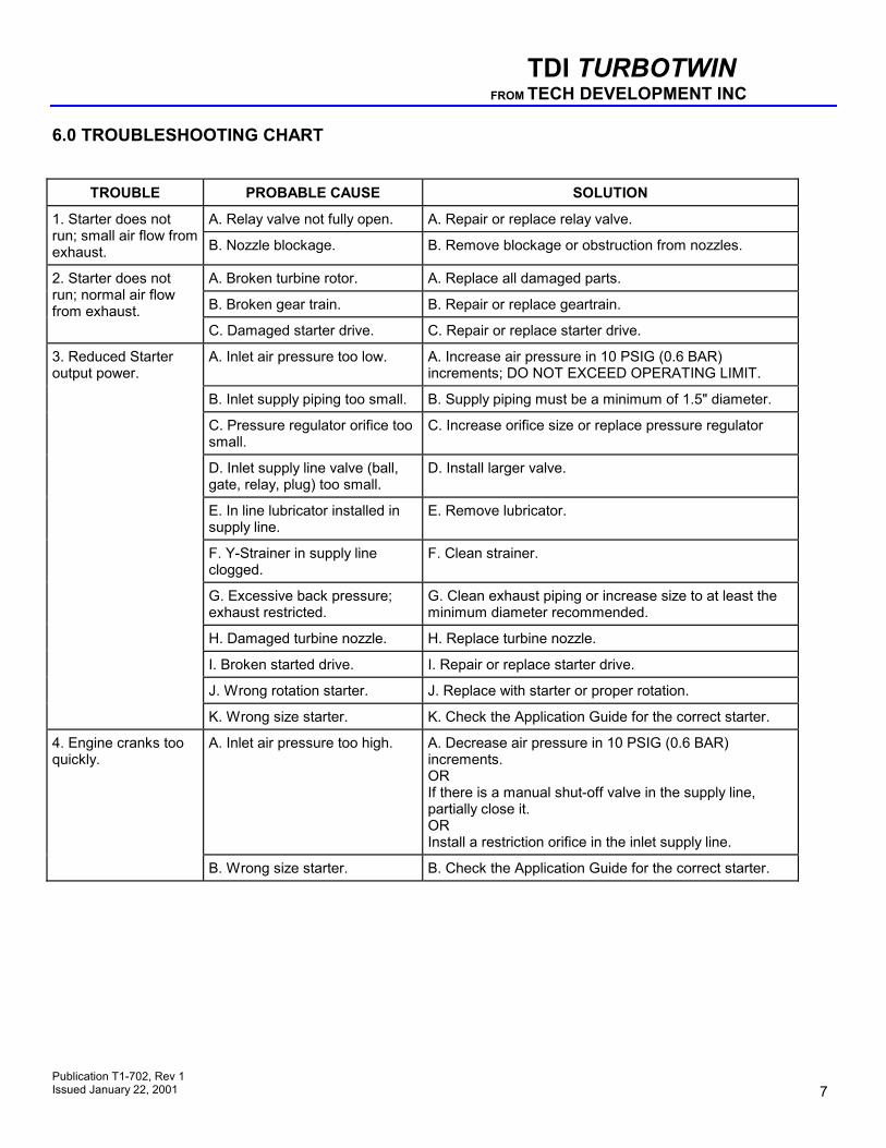
6.0 TROUBLESHOOTING CHART
TROUBLE
PROBABLE CAUSE SOLUTION
A. Relay valve not fully open.
A. Repair or replace relay valve.
1. Starter does not run; small air flow from exhaust.
B. Nozzle blockage.
B. Remove blockage or obstruction from nozzles.
A. Broken turbine rotor.
A. Replace all damaged parts.
B. Broken gear train.
B. Repair or replace geartrain.
2. Starter does not run; normal air flow from exhaust.
C. Damaged starter drive. C. Repair or replace starter drive.
A. Inlet air pressure too low.
A. Increase air pressure in 10 PSIG (0.6 BAR) increments; DO NOT EXCEED OPERATING LIMIT.
B. Inlet supply piping too small.
B. Supply piping must be a minimum of 1.5" diameter.
C. Pressure regulator orifice too small.
C. Increase orifice size or replace pressure regulator
D. Inlet supply line valve (ball, gate, relay, plug) too small.
D. Install larger valve.
E. In line lubricator installed in supply line.
E. Remove lubricator.
F. Y-Strainer in supply line clogged.
F. Clean strainer.
G. Excessive back pressure; exhaust restricted.
G. Clean exhaust piping or increase size to at least the minimum diameter recommended.
H. Damaged turbine nozzle.
H. Replace turbine nozzle.
I. Broken started drive.
I. Repair or replace starter drive.
J. Wrong rotation starter.
J. Replace with starter or proper rotation.
3. Reduced Starter output power.
K. Wrong size starter.
K. Check the Application Guide for the correct starter.
A. Inlet air pressure too high.
A. Decrease air pressure in 10 PSIG (0.6 BAR) increments. OR If there is a manual shut-off valve in the supply line, partially close it. OR Install a restriction orifice in the inlet supply line.
4. Engine cranks too quickly.
B. Wrong size starter.
B. Check the Application Guide for the correct starter.
Publication T1-702, Rev 1 Issued January 22, 2001 7
TDI TURBOTWIN FROM TECH DEVELOPMENT INC 7.0 WARRANTY TDI TURBOTWIN ENGINE STARTER WARRANTY Tech Development Inc. (TDI) warrants to the original user of the TDI TurboTwin™ Model T30 Series air starters to be free from defects in material and workmanship for a period of one year from date of purchase by such user. The warranty period shall begin on the actual delivery date to the original user or twelve (12) months from the date of shipment from TDI, whichever comes first. The conditions of this warranty are: a) TDI is notified within this period by return of such product to TDI or its authorized distributor or dealer, transportation prepaid by user; b) such product has been installed according to TDI’s specifications; c) such product has not been misused, abused or improperly maintained by user; d) the defect is not the result of normal wear and tear; and e) such starter product has not been repaired with parts not manufactured or authorized by TDI, and TDI installation and repair procedures as outlined in the appropriate manual were properly followed. Tech Development Inc. shall, at its option, either repair or replace, without charge, any such starter product found by TDI’s examination to be defective, or by mutual agreement, refund the user’s purchase price in exchange for such starter product. Repairs or replacements are warranted for the remainder of the original warranty period. Tech Development Inc. makes no other warranty, and IMPLIED WARRANTIES INCLUDING ANY WARRANTY OR MERCHANTABILITY OR FITNESS FOR A PARTICULAR PURPOSE ARE HEREBY DISCLAIMED. This warranty constitutes the entire obligation of Tech Development Inc. relating to the sale and use of such product, and TDI’s maximum liability is limited to the purchase price of such product at the date of purchase. In no event shall TDI be liable for incidental, indirect, consequential or special damages of any nature arising from the sale or use of such engine starter product.
Publication T1-702, Rev 1 Issued January 22, 2001 Page 8
TDI TURBOTWIN FROM TECH DEVELOPMENT INC
Publication T1-702, Rev 1 Issued January 22, 2001 9
TDI TURBOTWIN FROM TECH DEVELOPMENT INC
Publication T1-702, Rev 1 Issued January 22, 2001 Page 10
TDI TURBOTWIN FROM TECH DEVELOPMENT INC
TDI TURBOTWIN FROM TECH DEVELOPMENT INC
Publication T1-702, Rev 1 Issued January 22, 2001 11
Publication T1-702, Rev 1 Issued January 22, 2001 11
TDI TURBOTWIN FROM TECH DEVELOPMENT INC
Publication T1-702, Rev 1 Issued January 22, 2001 Page 12
TDI TURBOTWIN FROM TECH DEVELOPMENT INC
Publication T1-702, Rev 1 Issued January 22, 2001 13
TDI TURBOTWIN FROM TECH DEVELOPMENT INC
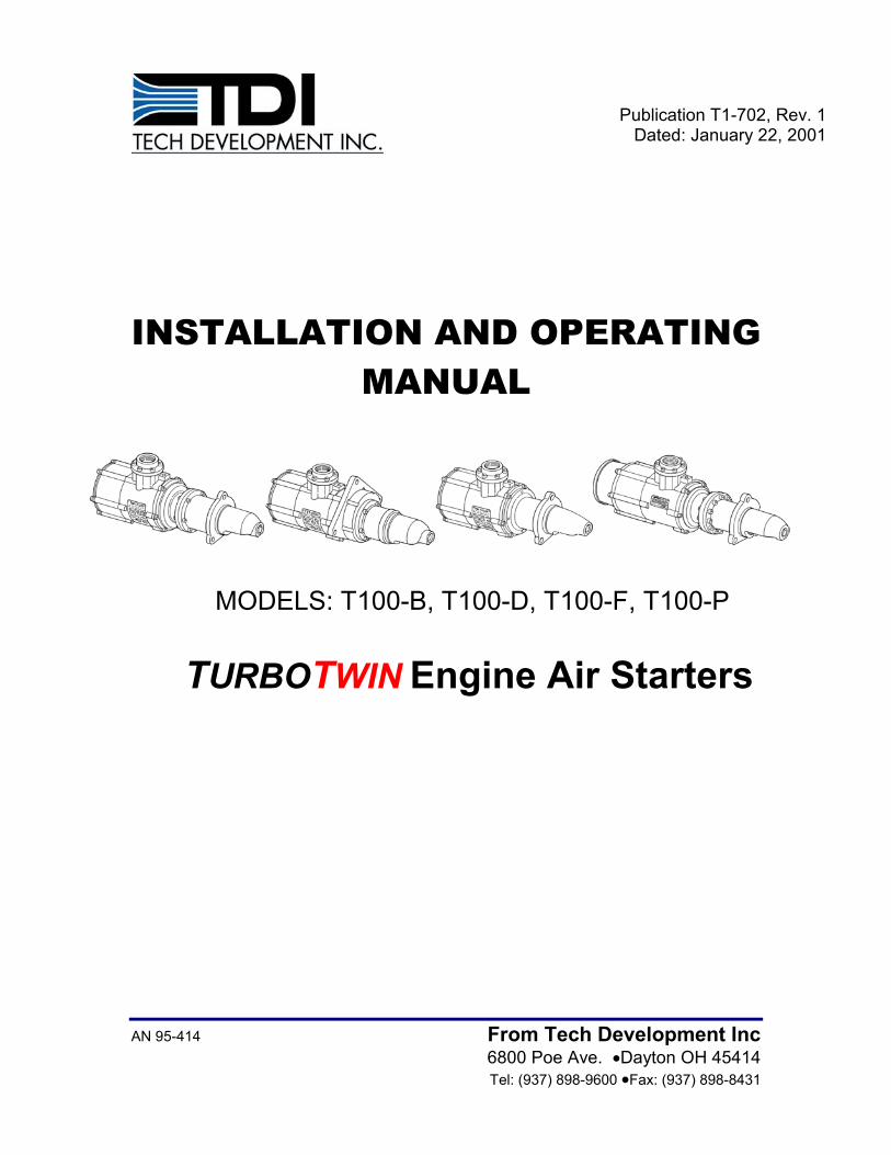
T112-B / T112-D Performance Curve12 Nozzles, Compressed Air, 7.5:1 RATIO
0 5 10 15 20 25 30 35 40 45 50 550
50
100
150
200
250
300
350
0
20
40
60
80
100
150 psig 1360 2312 120 psig 1090 1853 90 psig 860 146260 psig 610 1037
Maximum Torque Transmitted by Drive
150 psig
120 psig
90 psig
60 psig
HPLB.FTTORQUE POWER
Inlet Pressure SCFM Nm3/h
68
136
272
340
408
476
0
14.9
29.8
44.8
59.6
74.6
204
KWNm
68
136
204
272
340
408
476
Nm
0
14.9
29.8
44.8
59.6
74.6 KW
T121-B / T121-D Performance Curve21 Nozzles, Compressed Air, 7.5:1 RATIO
0 500 1000 1500 2000 2500 3000 3500 4000 4500 5000 55000
50
100
150
200
250
300
350
0
20
40
60
80
100
Inlet Pressure SCFM Nm3/h 90 psig 1560 2652 60 psig 1070 2140 30 psig 620 1054
Maximum Torque Transmitted by Drive
90 psig
60 psig
30 psig
LB.FT HP TORQUE POWER
Publication T1-702, Rev 1 Issued January 22, 2001 Page 14
TDI TURBOTWIN FROM TECH DEVELOPMENT INC
T106-F Performance Curve 6 Nozzles, Compressed Air, 7.5:1 RATIO
0 500 1000 1500 2000 2500 3000 3500 4000 4500 5000 55000
25
50
75
100
125
150
175
0
10
20
30
40
50
Maximum Torque Transmitted by Drive
90 psig
120 psig
150 psig
60 psig
HPPOWERTORQUE
Inlet Pressure SCFM Nm3/h 150 psig 680 1156 120 psig 550 935 90 psig 430 731 60 psig 310 527
0
14.9
29.8
KW
7.5
22.4
37.2
34
68
136
170
204
238
102
Nm LB. FT
0
33.5
KW
11.2
22.4
34
68
136
170
204
238
102
Nm LB.FT
Publication T1-702, Rev 1 Issued January 22, 2001 15
T112-F Performance Curve12 Nozzles, Compressed Air, 7.5:1 RATIO
0 500 1000 1500 2000 2500 3000 3500 4000 4500 5000 55000
25
50
75
100
125
150
175
0
15
30
45
Maximum Torque Transmitted by Drive
90 psig
60 psig
30 psig
HPPOWERTORQUE
Inlet Pressure SCFM Nm3/h 90 psig 860 1462 60 psig 610 1037 30 psig 370 629
TDI TURBOTWIN FROM TECH DEVELOPMENT INC
T109-P Performance Curve9 Nozzles, Compressed Air, 9.0:1 RATIO
0 500 1000 1500 2000 2500 3000 3500 4000 4500 5000 55000
50
100
150
200
250
300
350
0
20
40
60
80
90 psig
60 psig
DRIVE TORQUE LIMIT
120 psig
150 psig
150 psig 1050 1785120 psig 850 1445 90 psig 670 1139 60 psig 460 782
HPPOWER
LB.FTTORQUE
Inlet Pressure SCFM Nm3/h
68
136
272
340
408
476
204
0
14.9
29.8
44.8
59.6
KWNm
Publication T1-702, Rev 1 Issued January 22, 2001 Page 16