Embed Size (px)
Citation preview
Save These Instructions 3-90-30000369Vermont Castings • Aspen 1920 Owner's Manual_R35 • 02/18
For use in the United States and Canada
The French language version of this manual is available online:www.vermontcastings.comLa version française de ce manuel est disponible en ligne: www.vermontcastings.com
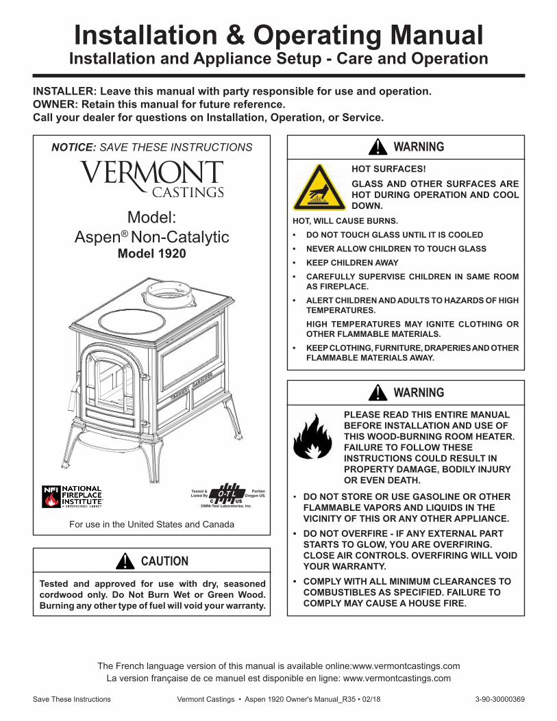
Model:Aspen® Non-Catalytic
Model 1920
Installation & Operating ManualInstallation and Appliance Setup - Care and Operation
INSTALLER: Leave this manual with party responsible for use and operation.OWNER: Retain this manual for future reference.Call your dealer for questions on Installation, Operation, or Service.
NOTICE: SAVE THESE INSTRUCTIONS
Tested and approved for use with dry, seasoned cordwood only. Do Not Burn Wet or Green Wood. Burning any other type of fuel will void your warranty.
CAUTION!
HOT, WILL CAUSE BURNS.• DO NOT TOUCH GLASS UNTIL IT IS COOLED• NEVER ALLOW CHILDREN TO TOUCH GLASS• KEEP CHILDREN AWAY• CAREFULLY SUPERVISE CHILDREN IN SAME ROOM
AS FIREPLACE.• ALERT CHILDREN AND ADULTS TO HAZARDS OF HIGH
TEMPERATURES. HIGH TEMPERATURES MAY IGNITE CLOTHING OR
OTHER FLAMMABLE MATERIALS.• KEEP CLOTHING, FURNITURE, DRAPERIES AND OTHER
FLAMMABLE MATERIALS AWAY.
HOT SURFACES!GLASS AND OTHER SURFACES ARE HOT DURING OPERATION AND COOL DOWN.
WARNING!
PLEASE READ THIS ENTIRE MANUAL BEFORE INSTALLATION AND USE OF THIS WOOD-BURNING ROOM HEATER. FAILURE TO FOLLOW THESE INSTRUCTIONS COULD RESULT IN PROPERTY DAMAGE, BODILY INJURY OR EVEN DEATH.
• DO NOT STORE OR USE GASOLINE OR OTHER FLAMMABLE VAPORS AND LIQUIDS IN THE VICINITY OF THIS OR ANY OTHER APPLIANCE.
• DO NOT OVERFIRE - IF ANY EXTERNAL PART STARTS TO GLOW, YOU ARE OVERFIRING. CLOSE AIR CONTROLS. OVERFIRING WILL VOID YOUR WARRANTY.
• COMPLY WITH ALL MINIMUM CLEARANCES TO COMBUSTIBLES AS SPECIFIED. FAILURE TO COMPLY MAY CAUSE A HOUSE FIRE.
WARNING!
2 Save These Instructions Vermont Castings • Aspen 1920 Owner's Manual_R35 • 02/18
Thank you for choosing a Vermont Castings Aspen to meet your heating needs. We’re confident you will find the Aspen to be an effective wood-burning heater incorporating modern, non-catalytic combustion technology with the classic aesthetic appeal of its Vermont Castings lineage.The Aspen achieves high-efficiency through precisely calibrated delivery of primary and secondary air into a refractory-insulated firebox. Properly operated and maintained according to the guidelines in this manual, your Aspen will provide safe, dependable, and economical heating for years to come. The Aspen Model 1920 is listed for burning wood fuel only. Do not burn other fuels. The Aspen Model 1920 complies with the standards set forth by the Federal Environmental Protection Agency, 40 CFR Part 60.532(b)(2), as stated on the permanent label attached to each stove.We recommend that you hire a professional, solid-fuel stove technician to install your Aspen, or to advise you on the installation should you attempt to install it yourself. Consult the authority having local jurisdiction (such as a municipal building department, fire department, fire prevention bureau, etc.) before installation to determine the need for a building permit. Also, consult your insurance agent to be sure your installation complies with specific requirements that may vary locally. In addition to directions on installation and operation, this manual includes directions on maintenance and assembly. Please read this entire manual before you install or operate your new room heater. Save These Instructions For Future Reference.
ATTENTION: CHAUD LORS DU FONC-TIONNEMENT- NE TOUCHEZ PAS L’APPAREIL-GARDEZ LES ENFANTS ET LES VÊTEMENTS ÉLOIGNÉS- TOUT CON-TACT PEUT ENTRAÎNER DES BRÛLURES DE LA PEAU. RÉ-FÉREZ-VOUS À LA PLAQUE SIGNALÉTIQUE ET AU MODE
D’EMPLOI. GARDEZ LE MOBILIER ET LES AUTRES MATÉRIAUX COMBUSTIBLES BIEN À L’ÉCART DE L’APPAREIL.
BARCODE LABELHFSerial No.No de série:
Rev G3-90-30000367
352 Mountain House RoadHalifax, PA 17032
ECO:
PART # / REV: 3-90-30000367_RevG
ORIGINATOR: SpidleT
DATE: 09/16
LABEL SIZE: 4.375” H x 11” W
LOCATION:
CLASS:
ADHESIVE:
MATERIAL: METAL
INK: BLACK BACKGROUND
OVERCOAT:
LABEL TICKET
ALL CAUTION LITERATURE IN RED(4) Holes = .156 x .250, Corners .062
Barcode label must have the serial number on it. The barcode label must be able to read Code 39 Full ASCII.
Date of Manufacture / Date de fabrication:2016 2017 2018 JAN FEB MAR APR MAY JUN JUL AUG SEP OCT NOV DEC
Manufactured by / Fabriqué par: Hearth and Home Technologies 352 Mountain House Road, Halifax PA 17032
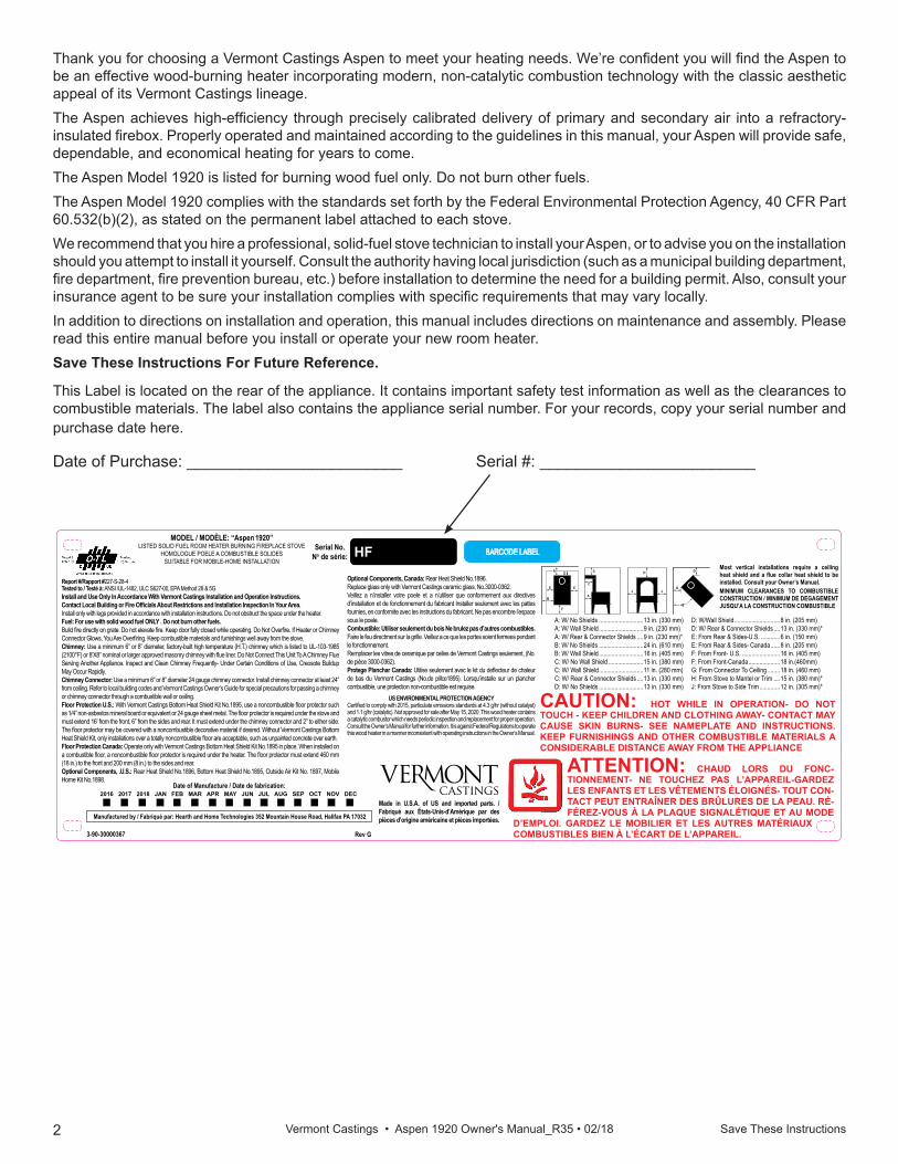
Report #/Rapport #227-S-28-4Tested to / Testé à: ANSI /UL-1482, ULC S627-00, EPA Method 28 & 5GInstall and Use Only In Accordance With Vermont Castings Installation and Operation Instructions. Contact Local Building or Fire Officials About Restrictions and Installation Inspection In Your Area.Install only with legs provided in accordance with installation instructions. Do not obstruct the space under the heater.Fuel: For use with solid wood fuel ONLY . Do not burn other fuels.Build fire directly on grate. Do not elevate fire. Keep door fully closed while operating. Do Not Overfire. If Heater or Chimney Connector Glows, You Are Overfiring. Keep combustible materials and furnishings well away from the stove. Chimney: Use a minimum 6” or 8” diameter, factory-built high temperature (H.T.) chimney which is listed to UL-103-1985 (2100°F) or 8’X8” nominal or larger approved masonry chimney with flue liner. Do Not Connect This Unit To A Chimney Flue Serving Another Appliance. Inspect and Clean Chimney Frequently- Under Certain Conditions of Use, Creosote Buildup May Occur Rapidly.Chimney Connector: Use a minimum 6” or 8” diameter 24 gauge chimney connector. Install chimney connector at least 24” from ceiling. Refer to local building codes and Vermont Castings Owner’s Guide for special precautions for passing a chimney or chimney connector through a combustible wall or ceiling.Floor Protection U.S.: With Vermont Castings Bottom Heat Shield Kit No.1895, use a noncombustible floor protector such as 1/4” non-asbestos mineral board or equivalent or 24 gauge sheet metal. The floor protector is required under the stove and must extend 16’ from the front, 6” from the sides and rear. lt must extend under the chimney connector and 2” to either side. The floor protector may be covered with a noncombustible decorative material if desired. Without Vermont Castings Bottom Heat Shield Kit, only installations over a totally noncombustible floor are acceptable, such as unpainted concrete over earth.Floor Protection Canada: Operate only with Vermont Castings Bottom Heat Shield Kit No.1895 in place. When installed on a combustible floor, a noncombustible floor protector is required under the heater. The floor protector must extend 460 mm (18 in.) to the front and 200 mm (8 in.) to the sides and rear.Optional Components, .U.S.: Rear Heat Shield No.1896, Bottom Heat Shield No.1895, Outside Air Kit No. 1897, Mobile Home Kit No.1898.
MODEL / MODÈLE: “Aspen 1920”LISTED SOLID FUEL ROOM HEATER BURNING FIREPLACE STOVE
HOMOLOGUE POELE A COMBUSTIBLE SOLIDESSUITABLE FOR MOBILE-HOME INSTALLATION
CAUTION: HOT WHILE IN OPERATION- DO NOT TOUCH - KEEP CHILDREN AND CLOTHING AWAY- CONTACT MAY CAUSE SKIN BURNS- SEE NAMEPLATE AND INSTRUCTIONS. KEEP FURNISHINGS AND OTHER COMBUSTIBLE MATERIALS A CONSIDERABLE DISTANCE AWAY FROM THE APPLIANCE
Most vertical installations require a ceiling heat shield and a flue collar heat shield to be installed. Consult your Owner’s Manual.MINIMUM CLEARANCES TO COMBUSTIBLE CONSTRUCTION / MINIMUM DE DEGAGEMENT JUSQU’A LA CONSTRUCTION COMBUSTIBLE
E
E E
F
B
A
D
D
45°
H
J J
G
C
A
Optional Components, Canada: Rear Heat Shield No.1896.Replace glass only with Vermont Castings ceramic glass, No.3000-0362.Veillez a n’installer votre poele et a n’utiliser que conformement aux directives d’installation et de fonctionne ment du fabricant Installer seulement avec les pattes fournies, en conformite avec les instructions du fabricant. Ne pas encombre l’espace sous le poele.Combustible: Utiliser seulement du bois Ne brulez pas d’autres combustibles. Faire le feu directment sur Ia grille. Veillez a ce que les portes soient fermees pendant le fonctionnement.Remplacer les vitres de ceramique par celles de Vermont Castings seulement, (No. de pièce 3000-0362).Protege Planchar Canada: Utilise seulement avec le kit du deflecteur de chaleur de bas du Vermont Castings (No.de pillce1895). Lorsqu’installe sur un plancher combustible, une protection non-combustible est requise.
US ENVIRONMENTAL PROTECTION AGENCYCertified to comply with 2015, particulate emissions standards at 4.3 g/hr (without catalyst) and 1.1 g/hr (catalytic). Not approved for sale after May 15, 2020. This wood heater contains a catalytic combustor which needs periodic inspection and replacement for proper operation. Consult the Owner’s Manual for further information. It is against Federal Regulations to operate this wood heater in a manner inconsistent with operating instructions in the Owner’s Manual.
A: W/ No Shields ............................13 in. (330 mm)A: W/ Wall Shield ............................9 in. (230 mm)A: W/ Rear & Connector Shields ....9 in. (230 mm)*B: W/ No Shields ............................24 in. (610 mm)B: W/ Wall Shield ............................16 in. (405 mm)C: W/ No Wall Shield ......................15 in. (380 mm)C: W/ Wall Shield ............................11 in. (280 mm)C: W/ Rear & Connector Shields ....13 in. (330 mm)D: W/ No Shields ............................13 in. (330 mm)
D: W/Wall Shield .............................8 in. (205 mm)D: W/ Rear & Connector Shields ....13 in. (330 mm)*E: From Rear & Sides-U.S. ............6 in. (150 mm)E: From Rear & Sides- Canada ......8 in. (205 mm)F: From Front- U.S. ........................16 in. (405 mm)F: From Front-Canada ....................18 in.(460mm)G: From Connector To Ceiling ........18 in. (460 mm)H: From Stove to Mantel or Trim ....15 in. (380 mm)*J: From Stove to Side Trim .............12 in. (305 mm)*
Made in U.S.A. of US and imported parts. / Fabriqué aux États-Unis-d’Amérique par des pièces d’origine américaine et pièces importées.
This Label is located on the rear of the appliance. It contains important safety test information as well as the clearances to combustible materials. The label also contains the appliance serial number. For your records, copy your serial number and purchase date here.
Date of Purchase: ________________________ Serial #: ________________________
3 Save These Instructions Vermont Castings • Aspen 1920 Owner's Manual_R35 • 02/18
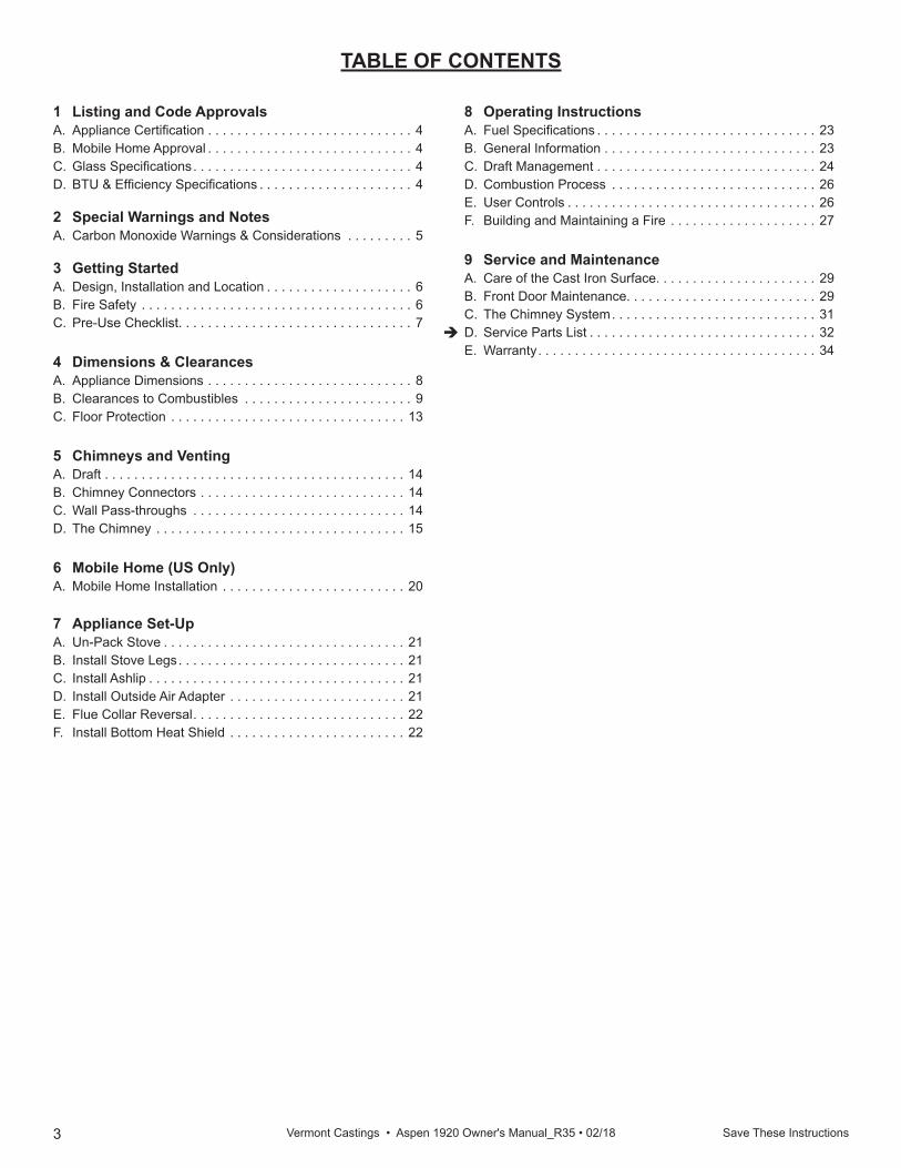
1 Listing and Code Approvals A. Appliance Certification . . . . . . . . . . . . . . . . . . . . . . . . . . . . 4B. Mobile Home Approval . . . . . . . . . . . . . . . . . . . . . . . . . . . . 4C. Glass Specifications . . . . . . . . . . . . . . . . . . . . . . . . . . . . . . 4D. BTU & Efficiency Specifications . . . . . . . . . . . . . . . . . . . . . 4
2 Special Warnings and Notes A. Carbon Monoxide Warnings & Considerations . . . . . . . . . 5
3 Getting Started A. Design, Installation and Location . . . . . . . . . . . . . . . . . . . . 6B. Fire Safety . . . . . . . . . . . . . . . . . . . . . . . . . . . . . . . . . . . . . 6C. Pre-Use Checklist. . . . . . . . . . . . . . . . . . . . . . . . . . . . . . . . 7
4 Dimensions & ClearancesA. Appliance Dimensions . . . . . . . . . . . . . . . . . . . . . . . . . . . . 8B. Clearances to Combustibles . . . . . . . . . . . . . . . . . . . . . . . 9C. Floor Protection . . . . . . . . . . . . . . . . . . . . . . . . . . . . . . . . 13
5 Chimneys and VentingA. Draft . . . . . . . . . . . . . . . . . . . . . . . . . . . . . . . . . . . . . . . . . 14B. Chimney Connectors . . . . . . . . . . . . . . . . . . . . . . . . . . . . 14C. Wall Pass-throughs . . . . . . . . . . . . . . . . . . . . . . . . . . . . . 14D. The Chimney . . . . . . . . . . . . . . . . . . . . . . . . . . . . . . . . . . 15
6 Mobile Home (US Only)A. Mobile Home Installation . . . . . . . . . . . . . . . . . . . . . . . . . 20
7 Appliance Set-UpA. Un-Pack Stove . . . . . . . . . . . . . . . . . . . . . . . . . . . . . . . . . 21B. Install Stove Legs . . . . . . . . . . . . . . . . . . . . . . . . . . . . . . . 21C. Install Ashlip . . . . . . . . . . . . . . . . . . . . . . . . . . . . . . . . . . . 21D. Install Outside Air Adapter . . . . . . . . . . . . . . . . . . . . . . . . 21E. Flue Collar Reversal . . . . . . . . . . . . . . . . . . . . . . . . . . . . . 22F. Install Bottom Heat Shield . . . . . . . . . . . . . . . . . . . . . . . . 22
TABLE OF CONTENTS
8 Operating InstructionsA. Fuel Specifications . . . . . . . . . . . . . . . . . . . . . . . . . . . . . . 23B. General Information . . . . . . . . . . . . . . . . . . . . . . . . . . . . . 23C. Draft Management . . . . . . . . . . . . . . . . . . . . . . . . . . . . . . 24D. Combustion Process . . . . . . . . . . . . . . . . . . . . . . . . . . . . 26E. User Controls . . . . . . . . . . . . . . . . . . . . . . . . . . . . . . . . . . 26F. Building and Maintaining a Fire . . . . . . . . . . . . . . . . . . . . 27
9 Service and MaintenanceA. Care of the Cast Iron Surface. . . . . . . . . . . . . . . . . . . . . . 29B. Front Door Maintenance. . . . . . . . . . . . . . . . . . . . . . . . . . 29C. The Chimney System . . . . . . . . . . . . . . . . . . . . . . . . . . . . 31D. Service Parts List . . . . . . . . . . . . . . . . . . . . . . . . . . . . . . . 32E. Warranty . . . . . . . . . . . . . . . . . . . . . . . . . . . . . . . . . . . . . . 34
4Save These Instructions Vermont Castings • Aspen 1920 Owner's Manual_R35 • 02/18
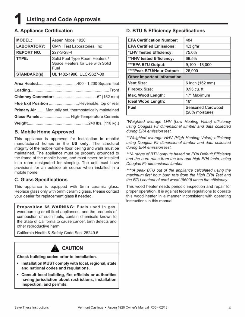
MODEL: Aspen Model 1920LABORATORY: OMNI Test Laboratories, IncREPORT NO. 227-S-28-4TYPE: Solid Fuel Type Room Heaters /
Space Heaters for Use with Solid Fuel
STANDARD(s): UL 1482-1996, ULC-S627-00
EPA Certification Number: 484EPA Certified Emissions: 4.3 g/hr*LHV Tested Efficiency: 75.0%**HHV tested Efficiency: 69.5%***EPA BTU Output: 9,100 - 18,000****Peak BTU/Hour Output: 26,900Other Important InformationVent Size: 6 Inch (152 mm)Firebox Size: 0.93 cu. ft.Max. Wood Length: 17" MaximumIdeal Wood Length: 16"Fuel Seasoned Cordwood
(20% moisture)
*Weighted average LHV (Low Heating Value) efficiency using Douglas Fir dimensional lumber and data collected during EPA emission test.**Weighted average HHV (High Heating Value) efficiency using Douglas Fir dimensional lumber and data collected during EPA emission test.***A range of BTU outputs based on EPA Default Efficiency and the burn rates from the low and high EPA tests, using Douglas Fir dimensional lumber.****A peak BTU out of the appliance calculated using the maximum first hour burn rate from the High EPA Test and the BTU content of cord wood (8600) times the efficiency.This wood heater needs periodic inspection and repair for proper operation. It is against federal regulations to operate this wood heater in a manner inconsistent with operating instructions in this manual.
Area Heated...................................400 - 1,200 Square feetLoading ....................................................................... FrontChimney Connector: ......................................6" (152 mm)Flue Exit Position ...........................Reversible, top or rear Primary Air ........Manually set, thermostatically maintainedGlass Panels ........................... High-Temperature CeramicWeight ......................................................240 lbs. (110 kg.)
1 Listing and Code Approvals
B. Mobile Home ApprovedThis appliance is approved for Installation in mobile/manufactured homes in the US only. The structural integrity of the mobile home floor, ceiling and walls must be maintained. The appliance must be properly grounded to the frame of the mobile home, and must never be installed in a room designated for sleeping. The unit must have provisions for an outside air source when installed in a mobile home.
C. Glass SpecificationsThis appliance is equipped with 5mm ceramic glass. Replace glass only with 5mm ceramic glass. Please contact your dealer for replacement glass if needed.
A. Appliance Certification D. BTU & Efficiency Specifications
Proposition 65 WARNING: Fuels used in gas, woodburning or oil fired appliances, and the products of combustion of such fuels, contain chemicals known to the State of California to cause cancer, birth defects and other reproductive harm.California Health & Safety Code Sec. 25249.6
Check building codes prior to installation.• Installation MUST comply with local, regional, state
and national codes and regulations.• Consult local building, fire officials or authorities
having jurisdiction about restrictions, installation inspection, and permits.
CAUTION!
5Save These Instructions Vermont Castings • Aspen 1920 Owner's Manual_R35 • 02/18
2 Special Warnings and Notes
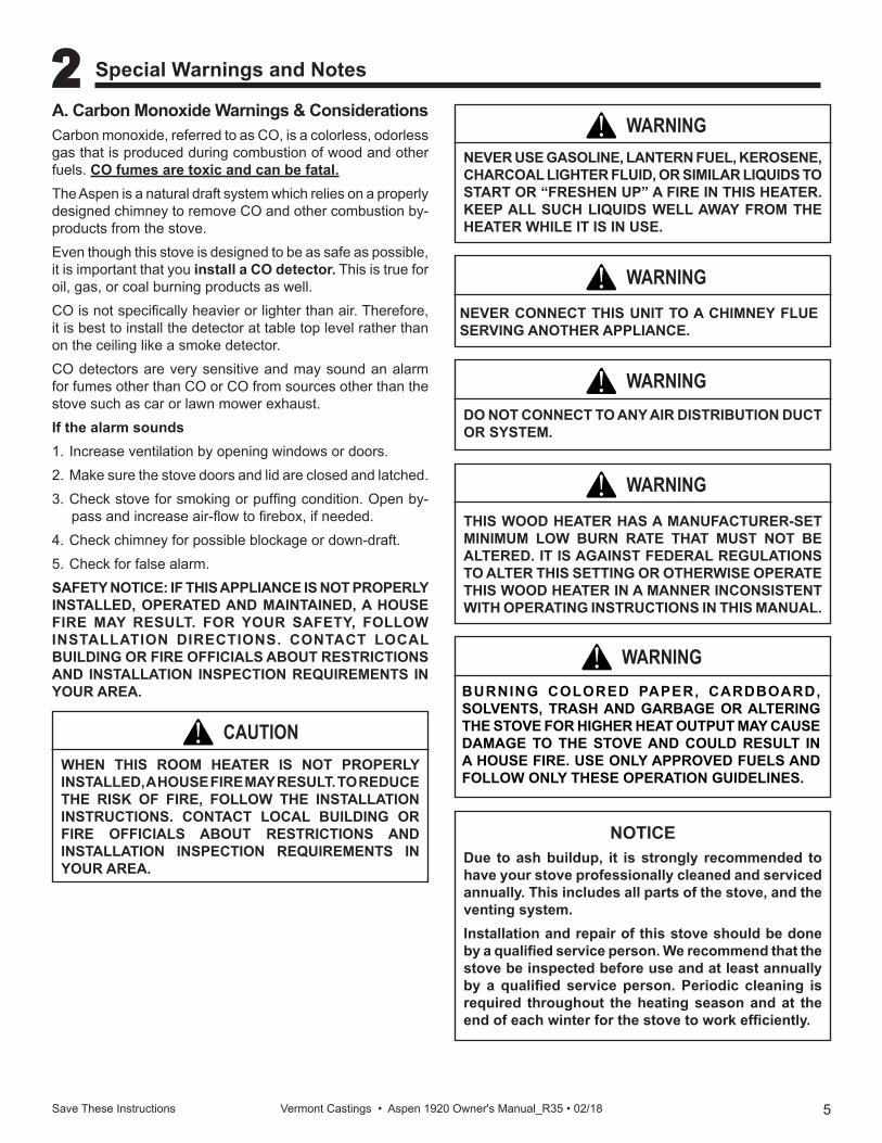
NOTICEDue to ash buildup, it is strongly recommended to have your stove professionally cleaned and serviced annually. This includes all parts of the stove, and the venting system.Installation and repair of this stove should be done by a qualified service person. We recommend that the stove be inspected before use and at least annually by a qualified service person. Periodic cleaning is required throughout the heating season and at the end of each winter for the stove to work efficiently.
WARNING!THIS WOOD HEATER HAS A MANUFACTURER-SET MINIMUM LOW BURN RATE THAT MUST NOT BE ALTERED. IT IS AGAINST FEDERAL REGULATIONS TO ALTER THIS SETTING OR OTHERWISE OPERATE THIS WOOD HEATER IN A MANNER INCONSISTENT WITH OPERATING INSTRUCTIONS IN THIS MANUAL.
BURNING COLORED PAPER, CARDBOARD, SOLVENTS, TRASH AND GARBAGE OR ALTERING THE STOVE FOR HIGHER HEAT OUTPUT MAY CAUSE DAMAGE TO THE STOVE AND COULD RESULT IN A HOUSE FIRE. USE ONLY APPROVED FUELS AND FOLLOW ONLY THESE OPERATION GUIDELINES.
WARNING!
NEVER USE GASOLINE, LANTERN FUEL, KEROSENE, CHARCOAL LIGHTER FLUID, OR SIMILAR LIQUIDS TO START OR “FRESHEN UP” A FIRE IN THIS HEATER. KEEP ALL SUCH LIQUIDS WELL AWAY FROM THE HEATER WHILE IT IS IN USE.
WARNING!
NEVER CONNECT THIS UNIT TO A CHIMNEY FLUE SERVING ANOTHER APPLIANCE.
WARNING!
DO NOT CONNECT TO ANY AIR DISTRIBUTION DUCT OR SYSTEM.
WARNING!
WHEN THIS ROOM HEATER IS NOT PROPERLY INSTALLED, A HOUSE FIRE MAY RESULT. TO REDUCE THE RISK OF FIRE, FOLLOW THE INSTALLATION INSTRUCTIONS. CONTACT LOCAL BUILDING OR FIRE OFFICIALS ABOUT RESTRICTIONS AND INSTALLATION INSPECTION REQUIREMENTS IN YOUR AREA.
CAUTION!
A. Carbon Monoxide Warnings & ConsiderationsCarbon monoxide, referred to as CO, is a colorless, odorless gas that is produced during combustion of wood and other fuels. CO fumes are toxic and can be fatal.The Aspen is a natural draft system which relies on a properly designed chimney to remove CO and other combustion by-products from the stove.Even though this stove is designed to be as safe as possible, it is important that you install a CO detector. This is true for oil, gas, or coal burning products as well.CO is not specifically heavier or lighter than air. Therefore, it is best to install the detector at table top level rather than on the ceiling like a smoke detector.CO detectors are very sensitive and may sound an alarm for fumes other than CO or CO from sources other than the stove such as car or lawn mower exhaust.If the alarm sounds 1. Increase ventilation by opening windows or doors.2. Make sure the stove doors and lid are closed and latched.3. Check stove for smoking or puffing condition. Open by-
pass and increase air-flow to firebox, if needed.4. Check chimney for possible blockage or down-draft.5. Check for false alarm.SAFETY NOTICE: IF THIS APPLIANCE IS NOT PROPERLY INSTALLED, OPERATED AND MAINTAINED, A HOUSE FIRE MAY RESULT. FOR YOUR SAFETY, FOLLOW INSTALLATION DIRECTIONS. CONTACT LOCAL BUILDING OR FIRE OFFICIALS ABOUT RESTRICTIONS AND INSTALLATION INSPECTION REQUIREMENTS IN YOUR AREA.
6Save These Instructions Vermont Castings • Aspen 1920 Owner's Manual_R35 • 02/18
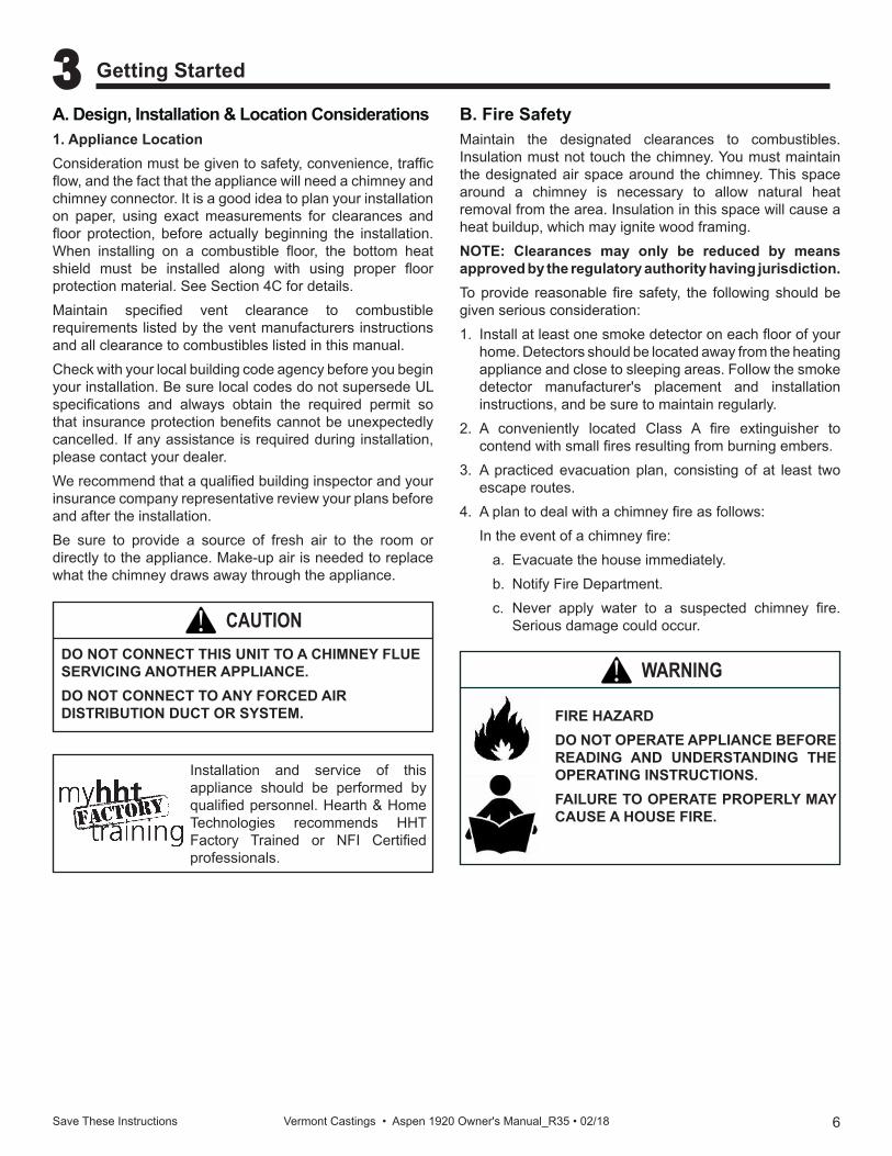
A. Design, Installation & Location Considerations1. Appliance LocationConsideration must be given to safety, convenience, traffic flow, and the fact that the appliance will need a chimney and chimney connector. It is a good idea to plan your installation on paper, using exact measurements for clearances and floor protection, before actually beginning the installation. When installing on a combustible floor, the bottom heat shield must be installed along with using proper floor protection material. See Section 4C for details.Maintain specified vent clearance to combustible requirements listed by the vent manufacturers instructions and all clearance to combustibles listed in this manual.Check with your local building code agency before you begin your installation. Be sure local codes do not supersede UL specifications and always obtain the required permit so that insurance protection benefits cannot be unexpectedly cancelled. If any assistance is required during installation, please contact your dealer.We recommend that a qualified building inspector and your insurance company representative review your plans before and after the installation.Be sure to provide a source of fresh air to the room or directly to the appliance. Make-up air is needed to replace what the chimney draws away through the appliance.
B. Fire SafetyMaintain the designated clearances to combustibles. Insulation must not touch the chimney. You must maintain the designated air space around the chimney. This space around a chimney is necessary to allow natural heat removal from the area. Insulation in this space will cause a heat buildup, which may ignite wood framing.NOTE: Clearances may only be reduced by means approved by the regulatory authority having jurisdiction.To provide reasonable fire safety, the following should be given serious consideration:1. Install at least one smoke detector on each floor of your
home. Detectors should be located away from the heating appliance and close to sleeping areas. Follow the smoke detector manufacturer's placement and installation instructions, and be sure to maintain regularly.
2. A conveniently located Class A fire extinguisher to contend with small fires resulting from burning embers.
3. A practiced evacuation plan, consisting of at least two escape routes.
4. A plan to deal with a chimney fire as follows: In the event of a chimney fire:
a. Evacuate the house immediately.b. Notify Fire Department.c. Never apply water to a suspected chimney fire.
Serious damage could occur.
3 Getting Started
DO NOT CONNECT THIS UNIT TO A CHIMNEY FLUE SERVICING ANOTHER APPLIANCE.DO NOT CONNECT TO ANY FORCED AIR DISTRIBUTION DUCT OR SYSTEM.
CAUTION!
FIRE HAZARDDO NOT OPERATE APPLIANCE BEFORE READING AND UNDERSTANDING THE OPERATING INSTRUCTIONS.FAILURE TO OPERATE PROPERLY MAY CAUSE A HOUSE FIRE.
WARNING!
Installation and service of this appliance should be performed by qualified personnel. Hearth & Home Technologies recommends HHT Factory Trained or NFI Certified professionals.
7Save These Instructions Vermont Castings • Aspen 1920 Owner's Manual_R35 • 02/18
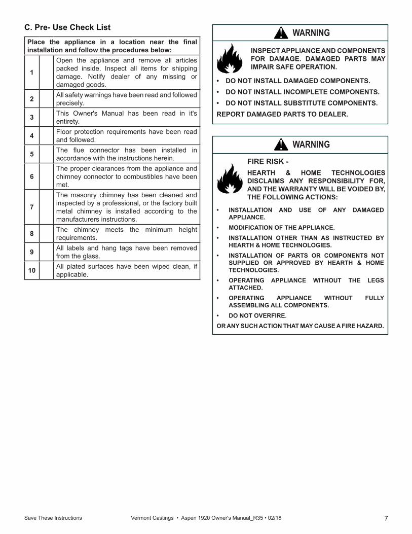
C. Pre- Use Check List
WARNING!FIRE RISK -HEARTH & HOME TECHNOLOGIES DISCLAIMS ANY RESPONSIBILITY FOR, AND THE WARRANTY WILL BE VOIDED BY, THE FOLLOWING ACTIONS:
• INSTALLATION AND USE OF ANY DAMAGED APPLIANCE.
• MODIFICATION OF THE APPLIANCE.• INSTALLATION OTHER THAN AS INSTRUCTED BY
HEARTH & HOME TECHNOLOGIES.• INSTALLATION OF PARTS OR COMPONENTS NOT
SUPPLIED OR APPROVED BY HEARTH & HOME TECHNOLOGIES.
• OPERATING APPLIANCE WITHOUT THE LEGS ATTACHED.
• OPERATING APPLIANCE WITHOUT FULLY ASSEMBLING ALL COMPONENTS.
• DO NOT OVERFIRE.OR ANY SUCH ACTION THAT MAY CAUSE A FIRE HAZARD.
Place the appliance in a location near the final installation and follow the procedures below:
1
Open the appliance and remove all articles packed inside. Inspect all items for shipping damage. Notify dealer of any missing or damaged goods.
2 All safety warnings have been read and followed precisely.
3 This Owner's Manual has been read in it's entirety.
4 Floor protection requirements have been read and followed.
5 The flue connector has been installed in accordance with the instructions herein.
6The proper clearances from the appliance and chimney connector to combustibles have been met.
7
The masonry chimney has been cleaned and inspected by a professional, or the factory built metal chimney is installed according to the manufacturers instructions.
8 The chimney meets the minimum height requirements.
9 All labels and hang tags have been removed from the glass.
10 All plated surfaces have been wiped clean, if applicable.
INSPECT APPLIANCE AND COMPONENTS FOR DAMAGE. DAMAGED PARTS MAY IMPAIR SAFE OPERATION.
WARNING!
• DO NOT INSTALL DAMAGED COMPONENTS.• DO NOT INSTALL INCOMPLETE COMPONENTS.• DO NOT INSTALL SUBSTITUTE COMPONENTS.REPORT DAMAGED PARTS TO DEALER.
8 Save These Instructions Vermont Castings • Aspen 1920 Owner's Manual_R35 • 02/18
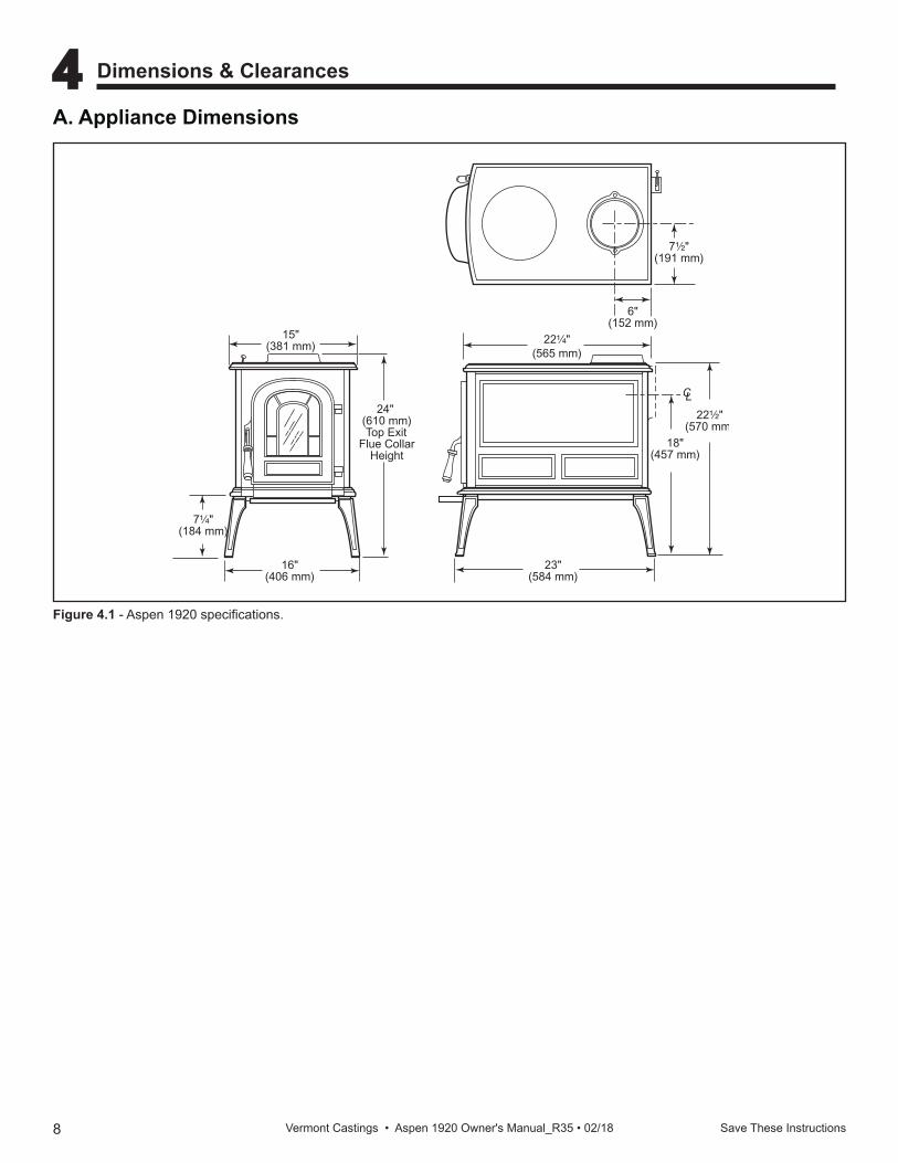
15"(381 mm)
24" (610 mm)Top Exit
Flue CollarHeight
16"(406 mm)
22¹⁄₂"(570 mm)
7¹⁄₄"(184 mm)
18"(457 mm)
23"(584 mm)
CL
6"(152 mm)
7¹⁄₂"(191 mm)
3069Aspen Specs2/15/00 djt
22¹⁄₄"(565 mm)
Figure 4.1 - Aspen 1920 specifications.
A. Appliance Dimensions
4 Dimensions & Clearances
9 Save These Instructions Vermont Castings • Aspen 1920 Owner's Manual_R35 • 02/18
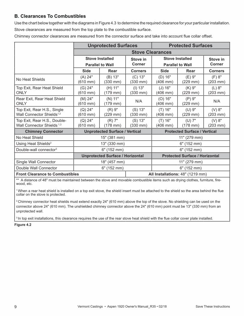
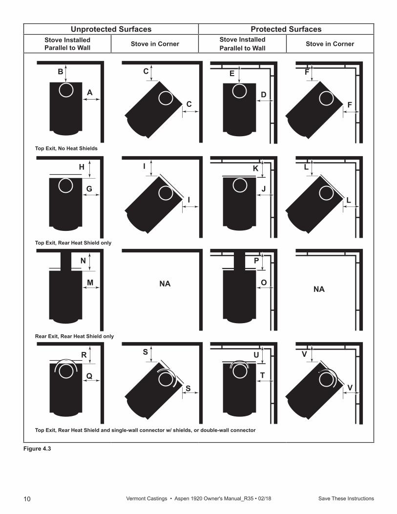
B. Clearances To CombustiblesUse the chart below together with the diagrams in Figure 4.3 to determine the required clearance for your particular installation.Stove clearances are measured from the top plate to the combustible surface.Chimney connector clearances are measured from the connector surface and take into account flue collar offset.
Unprotected Surfaces Protected SurfacesStove Clearances
Stove InstalledParallel to Wall
Stove in Corner
Stove InstalledParallel to Wall
Stove in Corner
Side Rear Corners Side Rear Corners
No Heat Shields (A) 24"(610 mm)
(B) 13"(330 mm)
(C) 13"(330 mm)
(D) 16"(406 mm)
(E) 9"(229 mm)
(F) 8"(203 mm)
Top Exit, Rear Heat Shield ONLY
(G) 24"(610 mm)
(H) 11"(179 mm)
(I) 13"(330 mm)
(J) 16"(406 mm)
(K) 9"(229 mm)
(L) 8"(203 mm)
Rear Exit, Rear Heat Shield ONLY
(M) 24"(610 mm)
(N) 11"(179 mm) N/A (O) 16"
(406 mm)(P) 9"
(229 mm) N/A
Top Exit, Rear H.S., Single Wall Connector Shields1,2
(Q) 24"(610 mm)
(R) 9"(229 mm)
(S) 13"(330 mm)
(T) 16"(406 mm)
(U) 9"(229 mm)
(V) 8"(203 mm)
Top Exit, Rear H.S., Double-Wall Connector Shields 1,3
(Q) 24"(610 mm)
(R) 7"(178 mm)
(S) 13"(330 mm)
(T) 16"(406 mm)
(U) 7"(178 mm)
(V) 8"(203 mm)
Chimney Connector Unprotected Surface / Vertical Protected Surface / VerticalNo Heat Shield 15" (381 mm) 11" (279 mm)Using Heat Shields2 13" (330 mm) 6" (152 mm)Double-wall connector3 6" (152 mm) 6" (152 mm)
Unprotected Surface / Horizontal Protected Surface / HorizontalSingle Wall Connector 18" (457 mm) 11" (279 mm)Double Wall Connector 6" (152 mm) 6" (152 mm)Front Clearance to Combustibles All Installations: 48" (1219 mm)** A distance of 48" must be maintained between the stove and movable combustible items such as drying clothes, furniture, fire-wood, etc.
1 When a rear heat shield is installed on a top exit stove, the shield insert must be attached to the shield so the area behind the flue collar on the stove is protected.
2 Chimney connector heat shields must extend exactly 24" (610 mm) above the top of the stove. No shielding can be used on the connector above 24" (610 mm). The unshielded chimney connector above the 24" (610 mm) point must be 13" (330 mm) from an unprotected wall.
3 In top exit installations, this clearance requires the use of the rear stove heat shield with the flue collar cover plate installed.
Figure 4.2
10 Save These Instructions Vermont Castings • Aspen 1920 Owner's Manual_R35 • 02/18
Unprotected Surfaces Protected SurfacesStove InstalledParallel to Wall Stove in Corner Stove Installed
Parallel to Wall Stove in Corner
ST255exit diagram12/15/99 djt
S
B C
CD
E
F
J
K
NANA
O
R
N
M
Q
A
H
I
U
P
VT
S
G
Top Exit, No Heat Shields
Rear Exit, Rear Heat Shield only
Top Exit, Rear Heat Shield only
Top Exit, Rear Heat Shield and single-wall connector w/ shields, or double-wall connector
F
LI
V
L
Figure 4.3
11 Save These Instructions Vermont Castings • Aspen 1920 Owner's Manual_R35 • 02/18
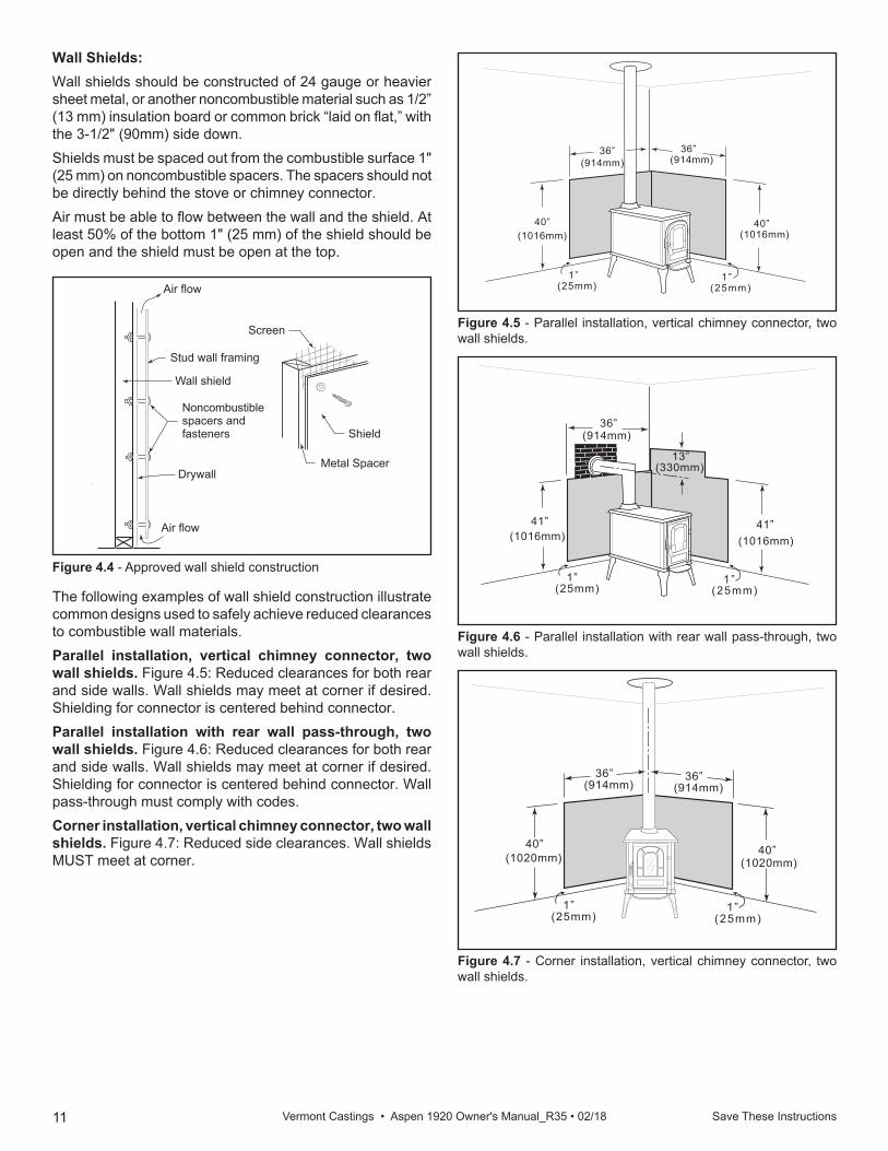
Figure 4.5 - Parallel installation, vertical chimney connector, two wall shields.
1”(25mm)
1”(25mm)
40”(1016mm)
40”(1016mm)
36”(914mm)
36”(914mm)
ST249parallel vertical wall shield12/14/99 djt
Figure 4.7 - Corner installation, vertical chimney connector, two wall shields.
1”(25mm)
1”(25mm)
40”(1020mm)
40”(1020mm)
36”(914mm)
36”(914mm)
ST251acorner installvertical12/14/99 djt
Figure 4.6 - Parallel installation with rear wall pass-through, two wall shields.
1”(25mm)
1”(25mm)
41”(1016mm)
41”(1016mm)
36”(914mm)
13”(330mm)
ST250parallel rear wall12/14/99 djt
The following examples of wall shield construction illustrate common designs used to safely achieve reduced clearances to combustible wall materials.Parallel installation, vertical chimney connector, two wall shields. Figure 4.5: Reduced clearances for both rear and side walls. Wall shields may meet at corner if desired. Shielding for connector is centered behind connector.Parallel installation with rear wall pass-through, two wall shields. Figure 4.6: Reduced clearances for both rear and side walls. Wall shields may meet at corner if desired. Shielding for connector is centered behind connector. Wall pass-through must comply with codes. Corner installation, vertical chimney connector, two wall shields. Figure 4.7: Reduced side clearances. Wall shields MUST meet at corner.
Wall Shields:Wall shields should be constructed of 24 gauge or heavier sheet metal, or another noncombustible material such as 1/2” (13 mm) insulation board or common brick “laid on flat,” with the 3-1/2" (90mm) side down.Shields must be spaced out from the combustible surface 1" (25 mm) on noncombustible spacers. The spacers should not be directly behind the stove or chimney connector.Air must be able to flow between the wall and the shield. At least 50% of the bottom 1" (25 mm) of the shield should be open and the shield must be open at the top.
ST248wall shield construction12/14/99 djt
Air flow
Wall shield
Air flow
Stud wall framing
Noncombustible spacers and fasteners
Drywall
Screen
Metal Spacer
Shield
Figure 4.4 - Approved wall shield construction
12 Save These Instructions Vermont Castings • Aspen 1920 Owner's Manual_R35 • 02/18
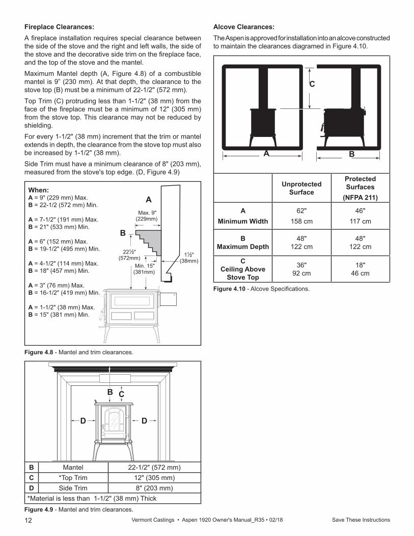
When: A = 9" (229 mm) Max.B = 22-1/2 (572 mm) Min.
A = 7-1/2" (191 mm) Max.B = 21" (533 mm) Min.
A = 6" (152 mm) Max.B = 19-1/2" (495 mm) Min.
A = 4-1/2" (114 mm) Max.B = 18" (457 mm) Min.
A = 3" (76 mm) Max.B = 16-1/2" (419 mm) Min.
A = 1-1/2" (38 mm) Max.B = 15" (381 mm) Min.
ST252amantel clrncs12/14/99 djt
Min. 15"(381mm)
11⁄2"(38mm)
Max. 9"(229mm)
221⁄2"(572mm)
A
B
Figure 4.8 - Mantel and trim clearances.
Unprotected Surface
Protected Surfaces
(NFPA 211)
AMinimum Width
62"158 cm
46"117 cm
BMaximum Depth
48"122 cm
48"122 cm
CCeiling Above
Stove Top
36"92 cm
18"46 cm
ST254alcove clearances12/99
Figure 4.10 - Alcove Specifications.
BA
C
Fireplace Clearances:A fireplace installation requires special clearance between the side of the stove and the right and left walls, the side of the stove and the decorative side trim on the fireplace face, and the top of the stove and the mantel.Maximum Mantel depth (A, Figure 4.8) of a combustible mantel is 9” (230 mm). At that depth, the clearance to the stove top (B) must be a minimum of 22-1/2" (572 mm).Top Trim (C) protruding less than 1-1/2" (38 mm) from the face of the fireplace must be a minimum of 12" (305 mm) from the stove top. This clearance may not be reduced by shielding. For every 1-1/2" (38 mm) increment that the trim or mantel extends in depth, the clearance from the stove top must also be increased by 1-1/2" (38 mm). Side Trim must have a minimum clearance of 8" (203 mm), measured from the stove's top edge. (D, Figure 4.9)
Alcove Clearances:The Aspen is approved for installation into an alcove constructed to maintain the clearances diagramed in Figure 4.10.
B Mantel 22-1/2" (572 mm)C *Top Trim 12" (305 mm)D Side Trim 8" (203 mm)*Material is less than 1-1/2" (38 mm) Thick
Figure 4.9 - Mantel and trim clearances.
ST253a aspentrim clearances12/15/99 djt
C
DD
B
13 Save These Instructions Vermont Castings • Aspen 1920 Owner's Manual_R35 • 02/18
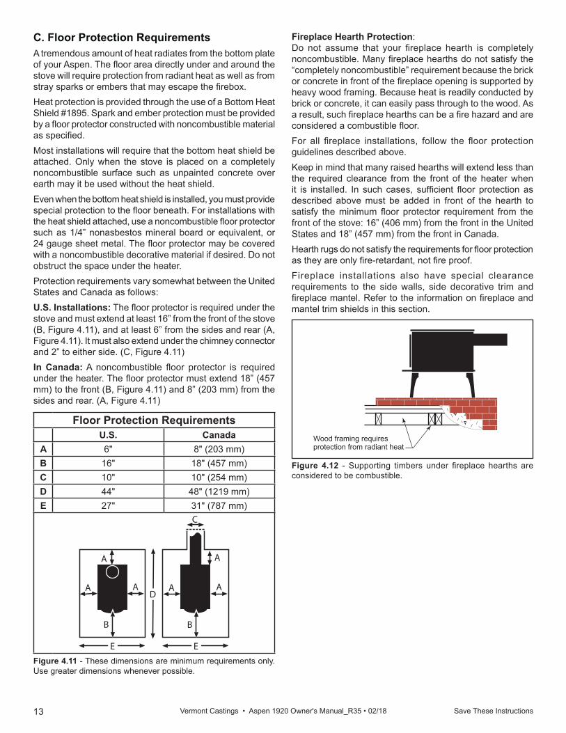
Figure 4.12 - Supporting timbers under fireplace hearths are considered to be combustible.
ST247Rear exit floor dgrm12/14/99 djt
Wood framing requires protection from radiant heat
Fireplace Hearth Protection:Do not assume that your fireplace hearth is completely noncombustible. Many fireplace hearths do not satisfy the “completely noncombustible” requirement because the brick or concrete in front of the fireplace opening is supported by heavy wood framing. Because heat is readily conducted by brick or concrete, it can easily pass through to the wood. As a result, such fireplace hearths can be a fire hazard and are considered a combustible floor. For all fireplace installations, follow the floor protection guidelines described above.Keep in mind that many raised hearths will extend less than the required clearance from the front of the heater when it is installed. In such cases, sufficient floor protection as described above must be added in front of the hearth to satisfy the minimum floor protector requirement from the front of the stove: 16” (406 mm) from the front in the United States and 18” (457 mm) from the front in Canada. Hearth rugs do not satisfy the requirements for floor protection as they are only fire-retardant, not fire proof.Fireplace installations also have special clearance requirements to the side walls, side decorative trim and fireplace mantel. Refer to the information on fireplace and mantel trim shields in this section.
C. Floor Protection RequirementsA tremendous amount of heat radiates from the bottom plate of your Aspen. The floor area directly under and around the stove will require protection from radiant heat as well as from stray sparks or embers that may escape the firebox.Heat protection is provided through the use of a Bottom Heat Shield #1895. Spark and ember protection must be provided by a floor protector constructed with noncombustible material as specified.Most installations will require that the bottom heat shield be attached. Only when the stove is placed on a completely noncombustible surface such as unpainted concrete over earth may it be used without the heat shield.Even when the bottom heat shield is installed, you must provide special protection to the floor beneath. For installations with the heat shield attached, use a noncombustible floor protector such as 1/4” nonasbestos mineral board or equivalent, or 24 gauge sheet metal. The floor protector may be covered with a noncombustible decorative material if desired. Do not obstruct the space under the heater.Protection requirements vary somewhat between the United States and Canada as follows:U.S. Installations: The floor protector is required under the stove and must extend at least 16” from the front of the stove (B, Figure 4.11), and at least 6” from the sides and rear (A, Figure 4.11). It must also extend under the chimney connector and 2” to either side. (C, Figure 4.11)In Canada: A noncombustible floor protector is required under the heater. The floor protector must extend 18” (457 mm) to the front (B, Figure 4.11) and 8” (203 mm) from the sides and rear. (A, Figure 4.11)
Floor Protection RequirementsU.S. Canada
A 6" 8" (203 mm)B 16" 18" (457 mm)C 10" 10" (254 mm)D 44" 48" (1219 mm)E 27" 31" (787 mm)
C
A
B
A
A
A
A
B
A
E E
D
ST246floor protection12/99
Figure 4.11 - These dimensions are minimum requirements only. Use greater dimensions whenever possible.
14 Save These Instructions Vermont Castings • Aspen 1920 Owner's Manual_R35 • 02/18
5 Chimneys and Venting
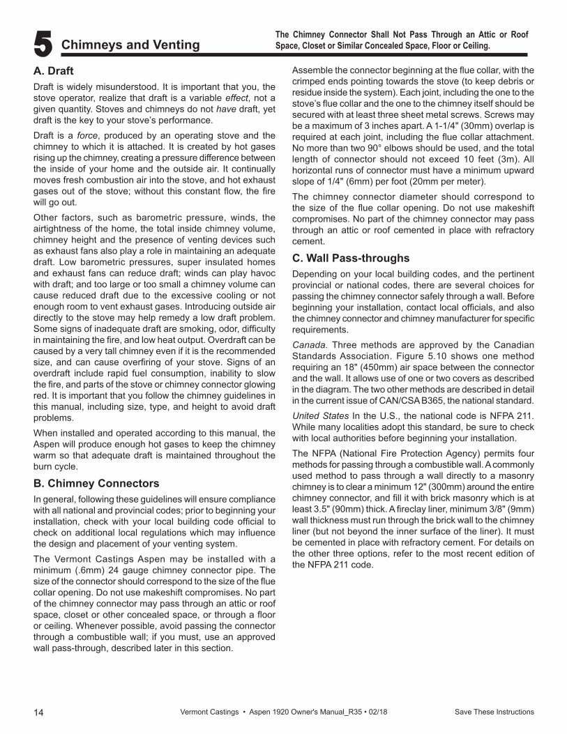
A. DraftDraft is widely misunderstood. It is important that you, the stove operator, realize that draft is a variable effect, not a given quantity. Stoves and chimneys do not have draft, yet draft is the key to your stove’s performance.Draft is a force, produced by an operating stove and the chimney to which it is attached. It is created by hot gases rising up the chimney, creating a pressure difference between the inside of your home and the outside air. It continually moves fresh combustion air into the stove, and hot exhaust gases out of the stove; without this constant flow, the fire will go out.Other factors, such as barometric pressure, winds, the airtightness of the home, the total inside chimney volume, chimney height and the presence of venting devices such as exhaust fans also play a role in maintaining an adequate draft. Low barometric pressures, super insulated homes and exhaust fans can reduce draft; winds can play havoc with draft; and too large or too small a chimney volume can cause reduced draft due to the excessive cooling or not enough room to vent exhaust gases. Introducing outside air directly to the stove may help remedy a low draft problem. Some signs of inadequate draft are smoking, odor, difficulty in maintaining the fire, and low heat output. Overdraft can be caused by a very tall chimney even if it is the recommended size, and can cause overfiring of your stove. Signs of an overdraft include rapid fuel consumption, inability to slow the fire, and parts of the stove or chimney connector glowing red. It is important that you follow the chimney guidelines in this manual, including size, type, and height to avoid draft problems.When installed and operated according to this manual, the Aspen will produce enough hot gases to keep the chimney warm so that adequate draft is maintained throughout the burn cycle.
B. Chimney ConnectorsIn general, following these guidelines will ensure compliance with all national and provincial codes; prior to beginning your installation, check with your local building code official to check on additional local regulations which may influence the design and placement of your venting system.The Vermont Castings Aspen may be installed with a minimum (.6mm) 24 gauge chimney connector pipe. The size of the connector should correspond to the size of the flue collar opening. Do not use makeshift compromises. No part of the chimney connector may pass through an attic or roof space, closet or other concealed space, or through a floor or ceiling. Whenever possible, avoid passing the connector through a combustible wall; if you must, use an approved wall pass-through, described later in this section.
The Chimney Connector Shall Not Pass Through an Attic or Roof Space, Closet or Similar Concealed Space, Floor or Ceiling.
Assemble the connector beginning at the flue collar, with the crimped ends pointing towards the stove (to keep debris or residue inside the system). Each joint, including the one to the stove’s flue collar and the one to the chimney itself should be secured with at least three sheet metal screws. Screws may be a maximum of 3 inches apart. A 1-1/4" (30mm) overlap is required at each joint, including the flue collar attachment. No more than two 90° elbows should be used, and the total length of connector should not exceed 10 feet (3m). All horizontal runs of connector must have a minimum upward slope of 1/4" (6mm) per foot (20mm per meter).The chimney connector diameter should correspond to the size of the flue collar opening. Do not use makeshift compromises. No part of the chimney connector may pass through an attic or roof cemented in place with refractory cement.
C. Wall Pass-throughsDepending on your local building codes, and the pertinent provincial or national codes, there are several choices for passing the chimney connector safely through a wall. Before beginning your installation, contact local officials, and also the chimney connector and chimney manufacturer for specific requirements.Canada. Three methods are approved by the Canadian Standards Association. Figure 5.10 shows one method requiring an 18" (450mm) air space between the connector and the wall. It allows use of one or two covers as described in the diagram. The two other methods are described in detail in the current issue of CAN/CSA B365, the national standard.United States In the U.S., the national code is NFPA 211. While many localities adopt this standard, be sure to check with local authorities before beginning your installation.The NFPA (National Fire Protection Agency) permits four methods for passing through a combustible wall. A commonly used method to pass through a wall directly to a masonry chimney is to clear a minimum 12" (300mm) around the entire chimney connector, and fill it with brick masonry which is at least 3.5" (90mm) thick. A fireclay liner, minimum 3/8" (9mm) wall thickness must run through the brick wall to the chimney liner (but not beyond the inner surface of the liner). It must be cemented in place with refractory cement. For details on the other three options, refer to the most recent edition of the NFPA 211 code.
15Save These Instructions Vermont Castings • Aspen 1920 Owner's Manual_R35 • 02/18
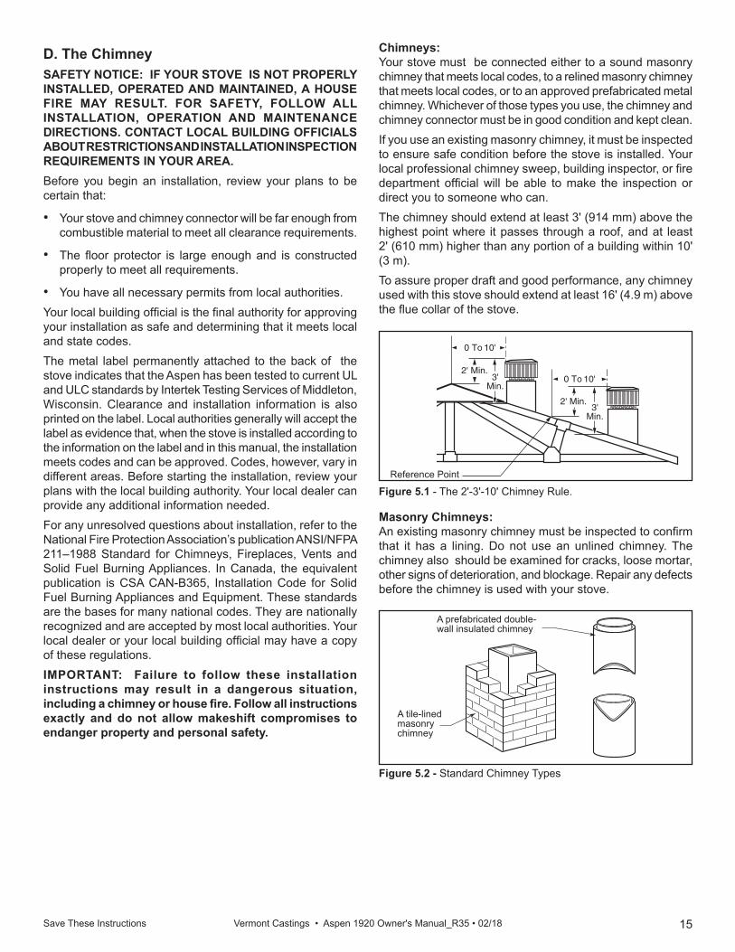
Figure 5.1 - The 2'-3'-10' Chimney Rule.
2' Min.
2' Min.
3'Min.
0 To 10'
3'Min.
0 To 10'
AC617RLTSKC8
2/11/98
Reference Point
Figure 5.2 - Standard Chimney Types
ST241chimney types12/13/99 djt
A prefabricated double-wall insulated chimney
A tile-lined masonry chimney
Masonry Chimneys:An existing masonry chimney must be inspected to confirm that it has a lining. Do not use an unlined chimney. The chimney also should be examined for cracks, loose mortar, other signs of deterioration, and blockage. Repair any defects before the chimney is used with your stove.
Chimneys:Your stove must be connected either to a sound masonry chimney that meets local codes, to a relined masonry chimney that meets local codes, or to an approved prefabricated metal chimney. Whichever of those types you use, the chimney and chimney connector must be in good condition and kept clean.If you use an existing masonry chimney, it must be inspected to ensure safe condition before the stove is installed. Your local professional chimney sweep, building inspector, or fire department official will be able to make the inspection or direct you to someone who can.The chimney should extend at least 3' (914 mm) above the highest point where it passes through a roof, and at least 2' (610 mm) higher than any portion of a building within 10' (3 m).To assure proper draft and good performance, any chimney used with this stove should extend at least 16' (4.9 m) above the flue collar of the stove.
D. The ChimneySAFETY NOTICE: IF YOUR STOVE IS NOT PROPERLY INSTALLED, OPERATED AND MAINTAINED, A HOUSE FIRE MAY RESULT. FOR SAFETY, FOLLOW ALL INSTALLATION, OPERATION AND MAINTENANCE DIRECTIONS. CONTACT LOCAL BUILDING OFFICIALS ABOUT RESTRICTIONS AND INSTALLATION INSPECTION REQUIREMENTS IN YOUR AREA.Before you begin an installation, review your plans to be certain that:
• Your stove and chimney connector will be far enough from combustible material to meet all clearance requirements.
• The floor protector is large enough and is constructed properly to meet all requirements.
• You have all necessary permits from local authorities.Your local building official is the final authority for approving your installation as safe and determining that it meets local and state codes.The metal label permanently attached to the back of the stove indicates that the Aspen has been tested to current UL and ULC standards by Intertek Testing Services of Middleton, Wisconsin. Clearance and installation information is also printed on the label. Local authorities generally will accept the label as evidence that, when the stove is installed according to the information on the label and in this manual, the installation meets codes and can be approved. Codes, however, vary in different areas. Before starting the installation, review your plans with the local building authority. Your local dealer can provide any additional information needed.For any unresolved questions about installation, refer to the National Fire Protection Association’s publication ANSI/NFPA 211–1988 Standard for Chimneys, Fireplaces, Vents and Solid Fuel Burning Appliances. In Canada, the equivalent publication is CSA CAN-B365, Installation Code for Solid Fuel Burning Appliances and Equipment. These standards are the bases for many national codes. They are nationally recognized and are accepted by most local authorities. Your local dealer or your local building official may have a copy of these regulations. IMPORTANT: Failure to follow these installation instructions may result in a dangerous situation, including a chimney or house fire. Follow all instructions exactly and do not allow makeshift compromises to endanger property and personal safety.

16 Save These Instructions Vermont Castings • Aspen 1920 Owner's Manual_R35 • 02/18
Chimney Connector Guidelines:A chimney connector is the double-wall or single-wall pipe that connects the stove to the chimney. The chimney itself is a masonry or prefabricated structure that encloses the flue. Chimney connectors are used only to make the connection from the stove to the chimney. They are for interior use only.Double-wall connectors must be tested and listed for use with solid-fuel burning appliances. Single-wall connectors should be made of 24 gauge or heavier steel, and should be 6" (152 mm) in diameter. Do not use galvanized chimney connector; it cannot withstand the high temperatures that can be reached by smoke and exhaust gases, and may release toxic fumes under high heat.If possible, do not pass the chimney connector through a combustible wall or ceiling. If passage through a combustible wall is unavoidable, refer to the recommendations in the section following on Wall Pass-throughs. Do not pass the connector through an attic, a closet or any similar concealed space. The whole chimney connector should be exposed and accessible for inspection and cleaning.Install the single wall chimney connector not less than 18" (457 mm) from the ceiling. Keep it as short and direct as possible, with no more than two 90 degree turns. If possible, use 45° elbows. Slope horizontal runs of connectors upward 1/4" per foot (20 mm per meter) going from the stove toward the chimney. The recommended maximum length of a horizontal run is 3' (914 mm), and the total length of chimney connector should be no longer than 8' (2.5 meters). In cathedral ceiling installations, extend the prefabricated chimney downward to within 8 feet (2.4m) of the stove.SAFETY NOTE: Always wear gloves and protective eyewear when drilling, cutting or joining chimney connector sections .Double-wall Chimney Connectors:The Aspen is approved for installation in the U.S. and Canada with double-wall chimney connectors that have been tested and listed for use with solid-fuel burning appliances by a recognized testing laboratory.Follow the instructions for assembling and installing double-wall connectors provided by the manufacturer of the double-wall chimney. To ease assembly and help assure safety, use chimney components manufactured by a single source.NOTE: For installations using double-wall connectors, minimum clearances must conform to those listed in the clearance chart in Section B - Figure 4.2.
ST242Chimney connector
12/13/99 djt
Flue gas direction
Toward stove
Figure 5.3 - Chimney connector.
Do not connect this unit to a chimney flue serving another appliance.NOTE: Do not vent this stove into a factory-built (zero-clearance) fireplace. This stove has not been tested and listed for that type of installation. Factory-built fireplaces and their chimneys are specifically designed as a unit for use as fireplaces. It may void the listing or be hazardous to adapt them for any other use.Do not connect the STOVE to any air distribution duct or system.
Masonry Chimneys, cont’d.:• Unused openings in an existing masonry chimney must
be sealed with masonry to the thickness of the chimney wall, and the chimney liner should be repaired. Openings sealed with pie plates or wallpaper are a hazard and should be sealed with mortar or refractory cement. In the event of a chimney fire, flames and smoke may be forced out of these unused thimbles.
• The chimney should be thoroughly cleaned before use.• A newly-built masonry chimney must conform to the
standards of local building code, or, in the absence of a local code, to a recognized national code. Masonry chimneys must be lined, either with code-approved masonry or precast refractory tiles, stainless steel pipe, or a code-approved, “poured-in-place” liner. The chimney clean-out door must seal tightly to ensure a good draft.
Prefabricated Chimneys:A prefabricated metal chimney must be one that is tested and listed for use with solid-fuel burning appliances to the High-Temperature (H.T.) Chimney Standard UL-103-1985 (2100°F.) for the United States, and High Temperature (650°C) Standard ULC S-629 for Canada. Chimney Size:This stove is approved for venting into a masonry chimney with a nominal flue size of 8" x 8" (203 x 203 mm), and into a round flue size of 8" (203 mm) or 6" (152 mm).It may be vented into larger chimneys as well. However, chimneys with liners larger than 8" x 12" (203 x 305 mm) may experience rapid cooling of smoke and reduction in draft, especially if they are located outside the home. Such large chimneys may need to be insulated or have the flue relined for proper stove performance. Ask your dealer about components available for connecting the stove to a steel chimney liner.
17Save These Instructions Vermont Castings • Aspen 1920 Owner's Manual_R35 • 02/18
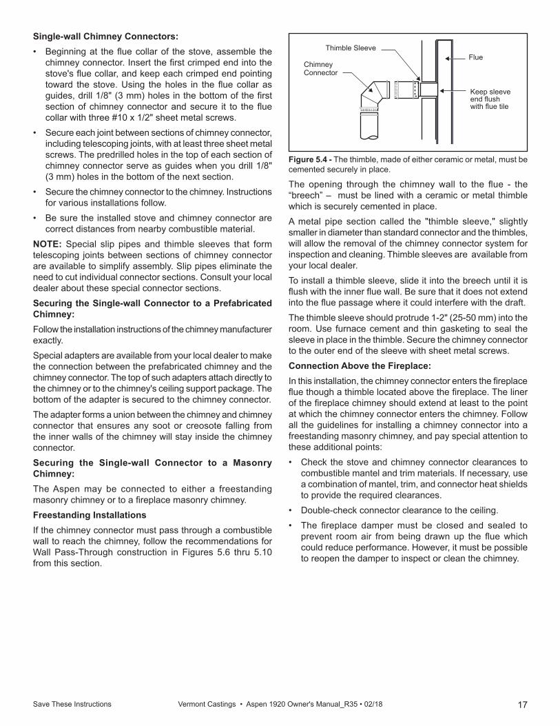
Figure 5.4 - The thimble, made of either ceramic or metal, must be cemented securely in place.
ST243thinble connection
12/13/99 djt
Chimney Connector
Thimble SleeveFlue
Keep sleeve end flush with flue tile
The opening through the chimney wall to the flue - the “breech” – must be lined with a ceramic or metal thimble which is securely cemented in place. A metal pipe section called the "thimble sleeve," slightly smaller in diameter than standard connector and the thimbles, will allow the removal of the chimney connector system for inspection and cleaning. Thimble sleeves are available from your local dealer.To install a thimble sleeve, slide it into the breech until it is flush with the inner flue wall. Be sure that it does not extend into the flue passage where it could interfere with the draft. The thimble sleeve should protrude 1-2" (25-50 mm) into the room. Use furnace cement and thin gasketing to seal the sleeve in place in the thimble. Secure the chimney connector to the outer end of the sleeve with sheet metal screws. Connection Above the Fireplace:In this installation, the chimney connector enters the fireplace flue though a thimble located above the fireplace. The liner of the fireplace chimney should extend at least to the point at which the chimney connector enters the chimney. Follow all the guidelines for installing a chimney connector into a freestanding masonry chimney, and pay special attention to these additional points:• Check the stove and chimney connector clearances to
combustible mantel and trim materials. If necessary, use a combination of mantel, trim, and connector heat shields to provide the required clearances.
• Double-check connector clearance to the ceiling.• The fireplace damper must be closed and sealed to
prevent room air from being drawn up the flue which could reduce performance. However, it must be possible to reopen the damper to inspect or clean the chimney.
Single-wall Chimney Connectors:• Beginning at the flue collar of the stove, assemble the
chimney connector. Insert the first crimped end into the stove's flue collar, and keep each crimped end pointing toward the stove. Using the holes in the flue collar as guides, drill 1/8" (3 mm) holes in the bottom of the first section of chimney connector and secure it to the flue collar with three #10 x 1/2" sheet metal screws.
• Secure each joint between sections of chimney connector, including telescoping joints, with at least three sheet metal screws. The predrilled holes in the top of each section of chimney connector serve as guides when you drill 1/8" (3 mm) holes in the bottom of the next section.
• Secure the chimney connector to the chimney. Instructions for various installations follow.
• Be sure the installed stove and chimney connector are correct distances from nearby combustible material.
NOTE: Special slip pipes and thimble sleeves that form telescoping joints between sections of chimney connector are available to simplify assembly. Slip pipes eliminate the need to cut individual connector sections. Consult your local dealer about these special connector sections.Securing the Single-wall Connector to a Prefabricated Chimney:Follow the installation instructions of the chimney manufacturer exactly. Special adapters are available from your local dealer to make the connection between the prefabricated chimney and the chimney connector. The top of such adapters attach directly to the chimney or to the chimney's ceiling support package. The bottom of the adapter is secured to the chimney connector.The adapter forms a union between the chimney and chimney connector that ensures any soot or creosote falling from the inner walls of the chimney will stay inside the chimney connector. Securing the Single-wall Connector to a Masonry Chimney:The Aspen may be connected to either a freestanding masonry chimney or to a fireplace masonry chimney.Freestanding Installations If the chimney connector must pass through a combustible wall to reach the chimney, follow the recommendations for Wall Pass-Through construction in Figures 5.6 thru 5.10 from this section.
18 Save These Instructions Vermont Castings • Aspen 1920 Owner's Manual_R35 • 02/18
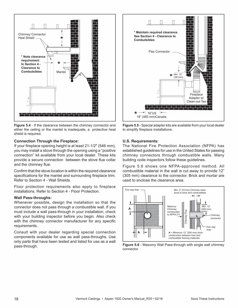
Figure 5.4 - If the clearance between the chimney connector and either the ceiling or the mantel is inadequate, a protective heat shield is required. ST244
Plymouthfplc over mantel12/99
* Note clearance requirement In Section 4 - Clearance to Combutsibles Mantel
Chimney Connector Heat Shield *
*
Figure 5.5 - Special adapter kits are available from your local dealer to simplify fireplace installations.
ST245fireplace flex connector12/99
* Maintain required clearance.See Section 4 - Clearance to Combutsibles
16”US 18” (460 mm)Canada
Flex Connector
Fireplace Adapter w/
Clean-out Tee
Min. 15” (381mm) *
*
Figure 5.6 - Masonry Wall Pass-through with single wall chimney connector.
ST272masonry wall pass throughw/ single wallconnector12/99
Min. 2” (51mm) Chimney clear-ance to brick and combustibles
A = Minimum 12” (305 mm) brick construction between liner and combustible framing materials
Min. 12” (305 mm)
Fire clay liner
A
A
Chi
mne
y Fl
ue
Fire clay liner
Masonry Chimney constructed to NFPA 211 Chimney
connector
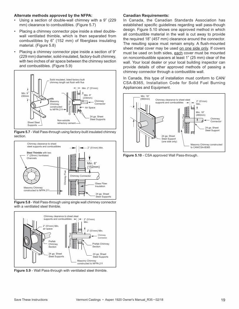
U.S. Requirements:The National Fire Protection Association (NFPA) has established guidelines for use in the United States for passing chimney connectors through combustible walls. Many building code inspectors follow these guidelines. Figure 5.6 shows one NFPA-approved method. All combustible material in the wall is cut away to provide 12” (305 mm) clearance to the connector. Brick and mortar are used to enclose the clearance area.
Connection Through the Fireplace:If your fireplace opening height is at least 21-1/2" (546 mm), you may install a stove through the opening using a “positive connection” kit available from your local dealer. These kits provide a secure connection between the stove flue collar and the chimney flue. Confirm that the stove location is within the required clearance specifications for the mantel and surrounding fireplace trim. Refer to Section 4 - Wall Shields.Floor protection requirements also apply to fireplace installations. Refer to Section 4 - Floor Protection.Wall Pass-throughs:Whenever possible, design the installation so that the connector does not pass through a combustible wall. If you must include a wall pass-through in your installation, check with your building inspector before you begin. Also check with the chimney connector manufacturer for any specific requirements.Consult with your dealer regarding special connection components available for use as wall pass-throughs. Use only parts that have been tested and listed for use as a wall pass-through.
19Save These Instructions Vermont Castings • Aspen 1920 Owner's Manual_R35 • 02/18
Figure 5.9 - Wall Pass-through with ventilated steel thimble.
ST275wall withventilatedsteel thimble
24 ga. Sheet Steel Supports
24 ga. Sheet Steel Supports
2” (51mm) Min.
Chimney clearance to sheet steel supports and combustibles 2” (51mm)
Min.
Chi
mne
y Fl
ue
2” (51mm) Min.air space
Prefab ChimneySection
Prefab ChimneySection
Chimney Connector
Masonry Chimney constructed to NFPA 211
Figure 5.8 - Wall Pass-through using single wall chimney connector with a ventilated steel thimble.
ST274single wall w/ventilated thimble12/99
Min. 6” (152mm)
Chimney clearance to sheet steel supports and combustibles 2” (51mm) Min.
Glass Fiber Insulation
Chimney Connector
Chi
mne
y Fl
ue
Steel Thimble with two 1” (25mm) Ventilated Channels
Masonry Chimney constructed to NFPA 211
24 ga. Sheet Steel Supports
Figure 5.10 - CSA approved Wall Pass-through.ST276CSA approved wall pass-through12/99
24 ga. Sheet Steel Support
24 ga. Sheet Steel Support(one side only)
Min. 18” (460mm)
Chimney clearance to sheet steel supports and combustibles 2” (51mm)
Min.
Chi
mne
y Fl
ue
ChimneyConnector
Masonry Chimney constructed to CAN/CSA-B365
Min. 18” (460mm)
Figure 5.7 - Wall Pass-through using factory-built insulated chimney section.
ST273nfpa factory built insulatedchimney section12/99
Min. 9” (230mm)
Air Space
Min. 9”230mm
Chi
mne
y Fl
ue
Sheet Steel Supports
Min. 2” (51mm)
Non-soluble refractory cement
Solid insulated, listed factory-built chimney length set flush with flue
Chimney Connector
Masonry Chimney constructed to NFPA 211
24 ga. Sheet Steel Supports
Canadian Requirements:In Canada, the Canadian Standards Association has established specific guidelines regarding wall pass-though design. Figure 5.10 shows one approved method in which all combustible material in the wall is cut away to provide the required 18” (457 mm) clearance around the connector. The resulting space must remain empty. A flush-mounted sheet metal cover may be used on one side only. If covers must be used on both sides, each cover must be mounted on noncombustible spacers at least 1” (25 mm) clear of the wall. Your local dealer or your local building inspector can provide details of other approved methods of passing a chimney connector through a combustible wall.In Canada, this type of installation must conform to CAN/CSA-B365, Installation Code for Solid Fuel Burning Appliances and Equipment.
Alternate methods approved by the NFPA: • Using a section of double-wall chimney with a 9” (229
mm) clearance to combustibles. (Figure 5.7)• Placing a chimney connector pipe inside a steel double-
wall ventilated thimble, which is then separated from combustibles by 6” (152 mm) of fiberglass insulating material. (Figure 5.8)
• Placing a chimney connector pipe inside a section of 9” (229 mm) diameter, solid-insulated, factory-built chimney, with two inches of air space between the chimney section and combustibles. (Figure 5.9)
20Save These Instructions Vermont Castings • Aspen 1920 Owner's Manual_R35 • 02/18
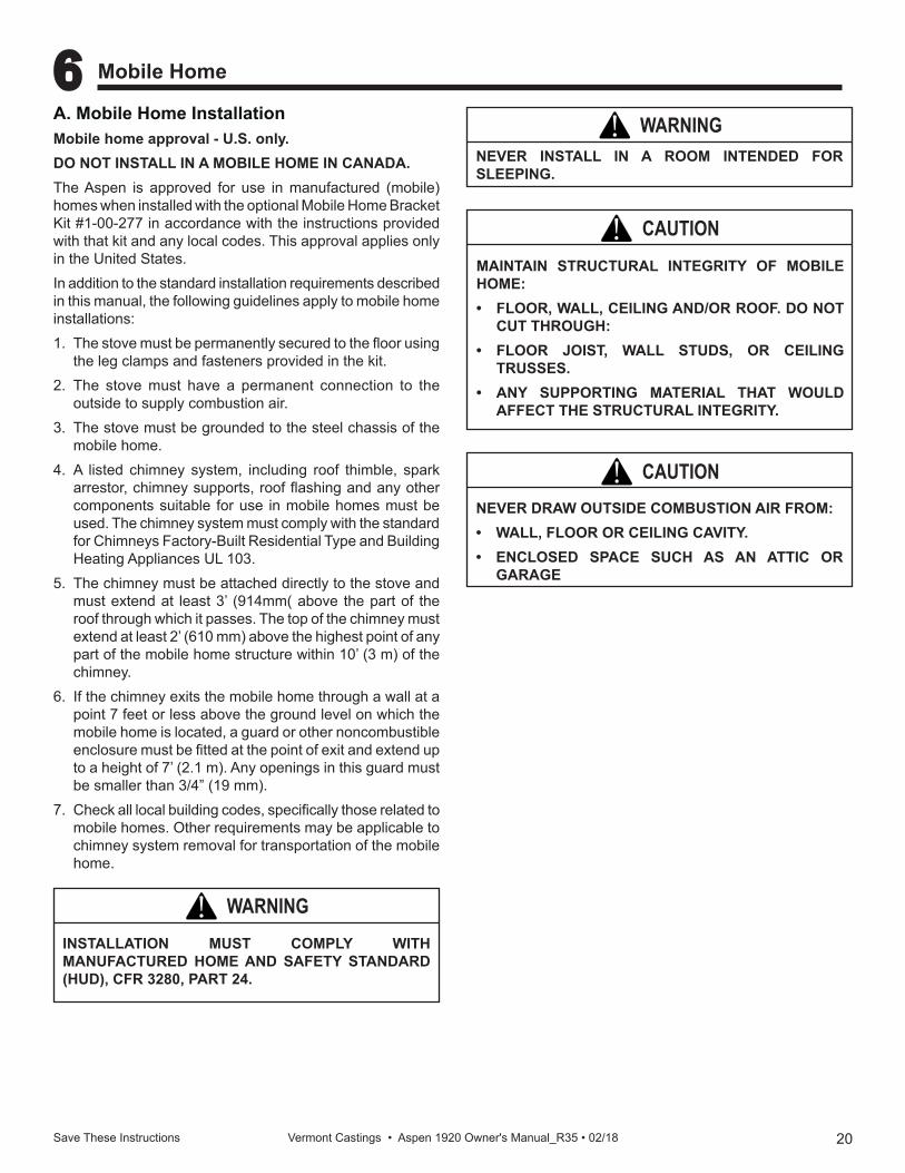
A. Mobile Home InstallationMobile home approval - U.S. only.DO NOT INSTALL IN A MOBILE HOME IN CANADA.The Aspen is approved for use in manufactured (mobile) homes when installed with the optional Mobile Home Bracket Kit #1-00-277 in accordance with the instructions provided with that kit and any local codes. This approval applies only in the United States.In addition to the standard installation requirements described in this manual, the following guidelines apply to mobile home installations:1. The stove must be permanently secured to the floor using
the leg clamps and fasteners provided in the kit.2. The stove must have a permanent connection to the
outside to supply combustion air.3. The stove must be grounded to the steel chassis of the
mobile home.4. A listed chimney system, including roof thimble, spark
arrestor, chimney supports, roof flashing and any other components suitable for use in mobile homes must be used. The chimney system must comply with the standard for Chimneys Factory-Built Residential Type and Building Heating Appliances UL 103.
5. The chimney must be attached directly to the stove and must extend at least 3’ (914mm( above the part of the roof through which it passes. The top of the chimney must extend at least 2’ (610 mm) above the highest point of any part of the mobile home structure within 10’ (3 m) of the chimney.
6. If the chimney exits the mobile home through a wall at a point 7 feet or less above the ground level on which the mobile home is located, a guard or other noncombustible enclosure must be fitted at the point of exit and extend up to a height of 7’ (2.1 m). Any openings in this guard must be smaller than 3/4” (19 mm).
7. Check all local building codes, specifically those related to mobile homes. Other requirements may be applicable to chimney system removal for transportation of the mobile home.
6 Mobile Home
INSTALLATION MUST COMPLY WITH MANUFACTURED HOME AND SAFETY STANDARD (HUD), CFR 3280, PART 24.
WARNING!
NEVER INSTALL IN A ROOM INTENDED FOR SLEEPING.
WARNING!
MAINTAIN STRUCTURAL INTEGRITY OF MOBILE HOME:• FLOOR, WALL, CEILING AND/OR ROOF. DO NOT
CUT THROUGH:• FLOOR JOIST, WALL STUDS, OR CEILING
TRUSSES.• ANY SUPPORTING MATERIAL THAT WOULD
AFFECT THE STRUCTURAL INTEGRITY.
CAUTION!
NEVER DRAW OUTSIDE COMBUSTION AIR FROM:• WALL, FLOOR OR CEILING CAVITY.• ENCLOSED SPACE SUCH AS AN ATTIC OR
GARAGE
CAUTION!
21 Save These Instructions Vermont Castings • Aspen 1920 Owner's Manual_R35 • 02/18
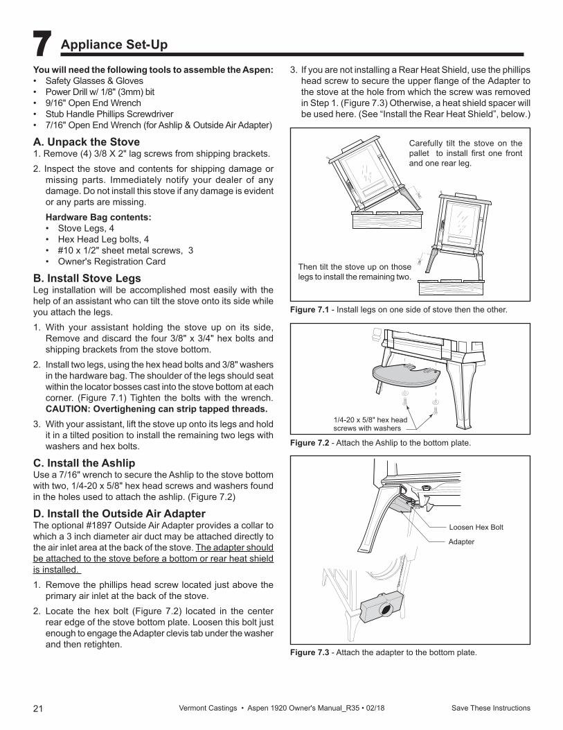
Figure 7.2 - Attach the Ashlip to the bottom plate.
ST257install ashlip12/99
1/4-20 x 5/8" hex head screws with washers
ST256attach legs12/15/99 djt
Carefully tilt the stove on the pallet to install first one front and one rear leg.
Then tilt the stove up on those legs to install the remaining two.
Figure 7.1 - Install legs on one side of stove then the other.
Figure 7.3 - Attach the adapter to the bottom plate.
ST258install outsideadapter12/15/99 djt
Loosen Hex Bolt
Adapter
You will need the following tools to assemble the Aspen:• Safety Glasses & Gloves• Power Drill w/ 1/8" (3mm) bit • 9/16" Open End Wrench• Stub Handle Phillips Screwdriver• 7/16" Open End Wrench (for Ashlip & Outside Air Adapter)
A. Unpack the Stove1. Remove (4) 3/8 X 2" lag screws from shipping brackets.2. Inspect the stove and contents for shipping damage or
missing parts. Immediately notify your dealer of any damage. Do not install this stove if any damage is evident or any parts are missing.Hardware Bag contents:• Stove Legs, 4 • Hex Head Leg bolts, 4• #10 x 1/2" sheet metal screws, 3• Owner's Registration Card
B. Install Stove LegsLeg installation will be accomplished most easily with the help of an assistant who can tilt the stove onto its side while you attach the legs.1. With your assistant holding the stove up on its side,
Remove and discard the four 3/8" x 3/4" hex bolts and shipping brackets from the stove bottom.
2. Install two legs, using the hex head bolts and 3/8" washers in the hardware bag. The shoulder of the legs should seat within the locator bosses cast into the stove bottom at each corner. (Figure 7.1) Tighten the bolts with the wrench. CAUTION: Overtighening can strip tapped threads.
3. With your assistant, lift the stove up onto its legs and hold it in a tilted position to install the remaining two legs with washers and hex bolts.
C. Install the AshlipUse a 7/16" wrench to secure the Ashlip to the stove bottom with two, 1/4-20 x 5/8" hex head screws and washers found in the holes used to attach the ashlip. (Figure 7.2)
D. Install the Outside Air AdapterThe optional #1897 Outside Air Adapter provides a collar to which a 3 inch diameter air duct may be attached directly to the air inlet area at the back of the stove. The adapter should be attached to the stove before a bottom or rear heat shield is installed. 1. Remove the phillips head screw located just above the
primary air inlet at the back of the stove.2. Locate the hex bolt (Figure 7.2) located in the center
rear edge of the stove bottom plate. Loosen this bolt just enough to engage the Adapter clevis tab under the washer and then retighten.
3. If you are not installing a Rear Heat Shield, use the phillips head screw to secure the upper flange of the Adapter to the stove at the hole from which the screw was removed in Step 1. (Figure 7.3) Otherwise, a heat shield spacer will be used here. (See “Install the Rear Heat Shield”, below.)
7 Appliance Set-Up
22Save These Instructions Vermont Castings • Aspen 1920 Owner's Manual_R35 • 02/18
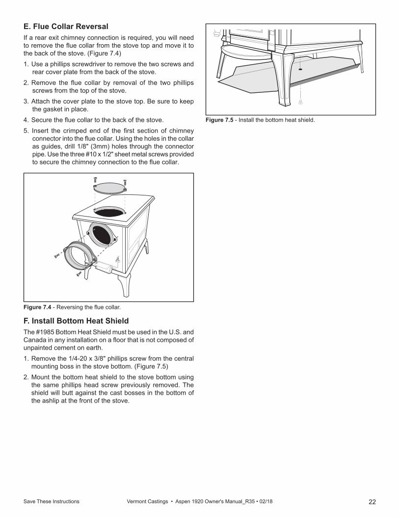
E. Flue Collar ReversalIf a rear exit chimney connection is required, you will need to remove the flue collar from the stove top and move it to the back of the stove. (Figure 7.4)1. Use a phillips screwdriver to remove the two screws and
rear cover plate from the back of the stove.2. Remove the flue collar by removal of the two phillips
screws from the top of the stove.3. Attach the cover plate to the stove top. Be sure to keep
the gasket in place.4. Secure the flue collar to the back of the stove.5. Insert the crimped end of the first section of chimney
connector into the flue collar. Using the holes in the collar as guides, drill 1/8" (3mm) holes through the connector pipe. Use the three #10 x 1/2" sheet metal screws provided to secure the chimney connection to the flue collar. ST261
install bottom heat shield12/99
Figure 7.5 - Install the bottom heat shield.
Figure 7.4 - Reversing the flue collar.
ST258flue collar reversal12/99
F. Install Bottom Heat ShieldThe #1985 Bottom Heat Shield must be used in the U.S. and Canada in any installation on a floor that is not composed of unpainted cement on earth.1. Remove the 1/4-20 x 3/8" phillips screw from the central
mounting boss in the stove bottom. (Figure 7.5)2. Mount the bottom heat shield to the stove bottom using
the same phillips head screw previously removed. The shield will butt against the cast bosses in the bottom of the ashlip at the front of the stove.
23Save These Instructions Vermont Castings • Aspen 1920 Owner's Manual_R35 • 02/18
A. Fuel SpecificationsSelect only dry, seasoned wood. Wood for burning should never be exposed to rain or extremely damp conditions. Hardwoods are favored because they are heavier and contain more heating capacity (BTU’s) per load than do softwoods. Fuel wood should be split and stored under cover for “seasoning” - at least a year is recommended. Your stove is not an incinerator - do not burn garbage, painted or treated wood, plastic, or other debris.Keep the area around the stove free from clutter. Keep all combustibles, including fuel, beyond the code-required clearance distance (48" or 1215mm in the U.S., 1525mm or 60" in Canada). Never store fuel in front of the stove where it could interfere with door operation, safe loading, and ash removal.
B. General InformationBefore you install and operate your Aspen wood stove, please read the entire contents of this manual. Pay particular attention to the explanation of draft and its effect on stove performance in the Installation section. By following the installation and operating guidelines, you will ensure proper draft and gain maximum efficiency and enjoyment from your stove.Do not alter the position of the andirons. Building a fire too close to the glass may cause damage to the glass, creating a serious risk of fire and property damage.
SAFETY NOTICEIF THIS APPLIANCE IS NOT PROPERLY INSTALLED, OPERATED AND MAINTAINED, A HOUSE FIRE MAY RESULT. FOR YOUR SAFETY, FOLLOW INSTALLATION DIRECTIONS. CONTACT LOCAL BUILDING OR FIRE OFFICIALS ABOUT RESTRICTIONS AND INSTALLATION INSPECTION REQUIREMENTS IN YOUR AREA.
8 Operating Instructions
CAUTION!Approved for use with wood fuel only. The use of any other fuel will void the product warranty and may cause damage to the appliance and/or your home.
"NEVER USE GASOLINE, GASOLINE-TYPE LANTERN FUEL, KEROSENE, CHARCOAL LIGHTER FLUID, OR SIMILAR LIQUIDS TO START OR "FRESHEN UP " A FIRE IN THIS HEATER. KEEP ALL SUCH LIQUIDS WELL AWAY FROM THE HEATER WHILE IN USE".
WARNING!
ALWAYS WEAR FIRE RETARDANT GLOVES WHEN OPERATING THE STOVE.
CAUTION!
BURNING COLORED PAPER, CARDBOARD, SOLVENTS, TRASH AND GARBAGE OR ALTERING THE STOVE FOR HIGHER HEAT OUTPUT MAY CAUSE DAMAGE TO THE STOVE AND COULD RESULT IN A HOUSE FIRE. USE ONLY APPROVED FUELS AND FOLLOW ONLY THESE OPERATION GUIDELINES.
WARNING!
WARNING!DO NOT BURN GARBAGE OR FLAMMABLE LIQUIDS SUCH AS GASOLINE, NAPTHA, OR ENGINE OIL.
24Save These Instructions Vermont Castings • Aspen 1920 Owner's Manual_R35 • 02/18
DO NOT USE CHEMICALS OR FLUIDS TO START THE FIRE. DO NOT BURN GARBAGE OR FLAMMABLE FLUIDS SUCH AS GASOLINE, NAPTHA, OR ENGINE OIL. Also, never use gasoline-type lantern fuel, kerosene, charcoal lighter fluid, or similar liquids to start or “freshen up” a fire. Keep all such liquids well away from the Aspen while it is in use.Caution: the Aspen will be hot while in operation. Keep children, clothing and furniture away. Contact may cause skin burns.DO NOT OVERFIRE THIS HEATER. Overfiring may cause a house fire, or can result in permanent damage to the stove. If any part of the stove glows, you are overfiring.
Safety Tips:Conveniently locate a "Class A" fire extinguisher to contend with small fires. Be sure the fire extinguisher works and is clearly visible. All occupants of the house should know where it is, and how it operates. Have heavy stove gloves available near the stove. Have special safety accessories (e.g., Child Guard Screen) available for use if small children will be in the home.In the event of a stove pipe or chimney fire….• Evacuate the house immediately• Notify the fire department• If the fire isn't too threatening, closing down the stove
tight, (primary air, all doors) will help to smother the fire. • Inspect your stove, stove pipe and chimney for any
damage caused by the fire and correct any damage before using your stove again.
WARNING!This wood heater has a manufactured-set minimum low burn rate that must not be altered. It is against federal regulations to alter this setting or otherwise operate this wood heater in a manner inconsistent with operating instructions in this manual.
C. Draft Management:Your stove is only one part of a system that includes the chimney, the operator, the fuel and the home. The other parts of the system will affect how well the stove works. When there is a good match between all the parts, the stove works well.
Wood stove operation depends on natural (unforced) draft. Natural draft occurs when exhaust gas is hotter (and therefore lighter) than the outdoor air at the top of the chimney. The greater the temperature difference, the stronger the draft. As the hot exhaust gas rises out of the chimney it generates suction that draws air into the stove for combustion. A slow, lazy fire with the stove’s air inlets fully open indicates a weak draft. A brisk fire, supported only by air entering the stove through the normal inlets, indicates a good draft. The inlets are passive; they regulate how much air can enter the stove, but they do not move air into it.The efficiency of a modern woodburning appliance, (in which the amount of air available for combustion is regulated), depends on the chimney to keep exhaust gases warm all the way outdoors. The characteristics of your chimney - whether it is steel or masonry, interior or exterior, matched or mismatched to the stove collar - determine how quickly it will warm up and how well it will sustain the optimum temperatures necessary to maintain strong draft and efficient combustion. Here follows a description of various flue system characteristics and related effects on stove performance.Masonry Chimney:Although masonry is the traditional material used for chimney construction, it can have distinct performance disadvantages when used to vent a controlled-combustion woodstove. Masonry forms an effective ‘heat sink’ - that is, it absorbs and holds heat for long periods of time. The large mass, however, may take a long time to become hot enough to sustain a strong draft. The larger the chimney (in total mass), the longer it will take to warm up. Cold masonry will actually cool exhaust gases enough to diminish draft strength. This problem is compounded if the chimney is located outside the home or if the chimney flue has a cross-sectional size larger than the stove outlet.Steel Chimney:Most factory-made ‘Class A’ steel chimneys have a layer of insulation around the inner flue. This insulation keeps the smoke warm and protects the surrounding structure from the high flue temperatures. Because the insulation is less dense than masonry, the inner steel liner warms up more quickly than a masonry chimney. Although steel chimneys are not as attractive as their masonry counterparts, they are very durable and generally outperform masonry.Inside/Outside Location:Because the chimney’s function is to keep the smoke warm, it is best to locate it inside the house. This location uses the house as insulation for the flue and allows some radiant heat release from the flue into the home. Since an interior chimney does not continuously lose its heat to the outdoors, it takes less heat from the stove to get it warm and keep it warm.
25Save These Instructions Vermont Castings • Aspen 1920 Owner's Manual_R35 • 02/18
Flue Sizing:The flue size for a controlled-combustion appliance should be based on the cross-sectional volume of the stove flue outlet. In this case, more is definitely not better. Hot gases lose heat through expansion; if a stove with a six-inch flue collar (28 square inch area) is vented into a 10” x 10” flue, the gases will expand to over three times their original volume. As gases cool with expansion, draft strength decreases. If an oversized flue is also outside the house, the heat it absorbs will be conducted to the outdoor air and the flue will remain relatively cool.It is common for a masonry flue to be oversized for the stove. Such a chimney can take quite a while to warm up and the stove performance will likely be disappointing. The best solution to an oversize flue problem is the installation of an insulated steel chimney liner of the same diameter as the appliance flue outlet. The liner keeps the exhaust gas warm and the result is a stronger draft. An uninsulated liner is a second choice - although the liner will keep the exhaust restricted to its original volume, the air around the liner will require time and heat energy to warm up.Check your local codes. You may be required to install a flue liner in any oversize or masonry flue.Pipe & Chimney Layout:Every bend in the flue will act as a brake on the exhaust as it flows from the firebox to the chimney cap. The ideal pipe and chimney layout is straight up from the stove through a completely straight chimney. Use this layout if at all possible as it will promote optimum stove performance and simplify maintenance.If the stovepipe must elbow to enter a chimney, locate the elbow about midway between the stove top and the chimney thimble. This configuration lets the smoke speed up before it must turn, keeps some pipe in the room for heat transfer, and allows long-term flexibility for installing a different appliance without relocating the thimble.There should be no more than eight feet of single-wall stove pipe between the stove and a chimney. Longer runs can cool the smoke enough to cause draft and creosote problems. Use double-wall stove pipe for longer runs.Single Venting:Your stove requires a dedicated flue. Do not connect the stove to a flue used by any other appliance. Chimney draft is a natural form of energy and follows the path of least resistance. If the stove is vented to a flue that also serves an open fireplace or another appliance, the draft will also pull air in through those avenues. The additional air flow will lower flue temperatures, reduce draft strength and promote creosote development; overall stove performance will suffer. The effect is similar to that of a vacuum cleaner with a hole in the hose. In some extreme instances, the other appliance can even impose a negative draft and result in a dangerous draft reversal.
Fuel:Even the best stove installation will not perform well if poor fuel is used. I available, always use hardwood that has been air-dried (‘seasoned’) 12-18 months. Softwood burns more rapidly than hardwood and has a high resin content conducive to creosote production. Decayed wood of any type has little heat value and should not be used.All unseasoned (‘green’) wood has a high moisture content. Much of its heat value will be used to evaporate moisture before the wood can burn. This significantly reduces not only the amount of energy available to warm your home, but also the intensity of the fire and temperature of the exhaust gas. Incomplete combustion and cool flue temperatures promote creosote formation and weak draft.You can judge the moisture content of wood by its appearance and weight or use a commercially available moisture meter for an exact measurement. Unseasoned wood will be a third heavier than dry wood. Also, look for cracks (‘checking’) in the ends of the log that result from contraction as the wood dries. The longer and wider the cracks, the dryer the wood is. Purchase your fuel from a reputable dealer.Creosote:Creosote is a by-product of low-temperature stove operations, weak draft or both. It is a tar that results when unburned gases condense inside the flue system at temperatures below 290°F. Creosote is volatile and can generate chimney fire. All of the installation characteristics that adversely affect chimney draft also promote creosote condensation. Consequently, you can minimize creosote accumulation with an effective chimney design and the use of operational techniques that encourage good draft and complete combustion.Backpuffing:Backpuffing is a condition that results when the draft is too weak to pull flue gases out of the chimney system as fast as the fire is generating more. Volatile gases build up within the firebox until reaching a density and temperature at which they ignite. With this ignition, you may hear a muffled popping sound and see a bit of smoke forced out of the air inlets.This condition is most likely to occur in the spring or fall when moderate outdoor temperatures and low intensity fires combine to inhibit draft strength. If your stove backpuffs open the air inlets to induce a livelier fire and speed airflow through the stove. Avoid large loads of firewood at one time. You should always see lively, dancing flames in the firebox; a lazy, smoky fire is inefficient and will promote draft problems.
26 Save These Instructions Vermont Castings • Aspen 1920 Owner's Manual_R35 • 02/18
Burn Only High-Quality WoodTHE ASPEN IS DESIGNED TO BURN NATURAL WOOD ONLY; DO NOT BURN ANY OTHER FUELS.You will enjoy the best results when burning wood that has been adequately air-dried. Avoid burning “green” wood that has not been properly seasoned. The wood should be no longer than 16” (410 mm) in length, however, you will find that shorter wood lengths ease refueling and promote the most efficient combustion.The best hardwood fuels include oak, maple, beech, ash, and hickory that has been split, stacked, and air-dried outside under cover for at least one year.For areas that do not have a supply of hardwood, commonly burned softwoods include tamarack, yellow pine, white pine, Eastern red cedar, fir, and redwood. These too should be properly dried. Keep wood a safe distance from the heater and keep it out of the areas around the heater used for refueling and ash removal.
E. User ControlsUse the Air Control Setting that Works Best for You:No single air control setting will be appropriate for every situation. Settings will differ depending on the quality of the fuel, the amount of heat desired, and how long you wish the fire to burn. The control setting also depends on your particular installation’s “draft,” or the force that moves air from the stove up through the chimney. Draft is affected by such things as the length, type, and location of the chimney, local geography, nearby obstructions, and other factors.Too much draft may cause excessive temperatures in the Aspen, and could even damage it. On the other hand, too little draft can cause backpuffing into the room and/or the “plugging” of the chimney.How do you know if your draft is excessively high or low? Symptoms of too much draft include an uncontrollable burn or a glowing-red stove part. A sign of inadequate draft is smoke leaking into the room through the stove or chimney connector joints, low heat, and dirty glass.In newer homes that are well-insulated and weather-tight, poor draft may result from insufficient air in the house. In such cases, a slightly opened window or door, near the stove on the windward side of the house will provide the fresh air needed. A more effective option for delivering ample combustion air to the stove is to duct air directly from outdoors to the stove. In fact, in some areas, provisions for outside combustion air are required in all new construction. The optional Aspen Outside Air Adapter #1897 is available from your dealer.When you first begin using the stove, pay attention to the air control settings. You will quickly find that a specific setting will give you a fixed amount of heat. It may take some time to determine the amount of heat and the length of burn you should expect from various settings.
Negative Pressure:Good draft also depends on a sufficient supply of air to the stove. The chimney cannot pull more air than is available. Sluggish draft can be caused by a house that is tight enough to prevent the ready flow of air to the stove, or by competition between the stove and other appliances that vent indoor air to the outside; i.e., exhaust fans for range hoods, clothes dryers, bathroom, etc. If the chimney draws well when all such equipment is turned off (or sealed, in the case of the fireplaces and/or other stoves), you simply need to be attentive in timing the use of the other appliances. If you need to crack a nearby window or door to enable the chimney to pull well, you should install an outside-air intake to bring combustion air directly to the stove. Consult your Vermont Castings’ dealer regarding an adapter to attach to the stove to connect an air duct for outdoor combustion air.Conclusion:Woodburning is more an art than a science. Art includes technique and since installations, homes and fuel vary, the stove operator must also vary technique, (mostly timing), to achieve satisfying results. Over time, you will become familiar with the intricacies and nuances of your particular installation and you will be able to identify cause and effect in a variety of seasonal circumstances.
D. Combustion ProcessHow the Aspen Works:Combustion control is achieved in the Aspen through two separate air delivery systems. The primary air control lever, located at the left rear corner of the stove, controls the amount of incoming primary air for starting, maintaining, and reviving the fire. More air entering the stove makes the fire burn hotter and faster, while less air prolongs the burn at a lower heat level.For the greatest air supply and maximum heat output (but the shortest burn time), move the lever to the straight up (12 o’clock) position. For a fire that will last longer with less heat, move the lever to the right. You can set the lever anywhere in between the left and right extremes.The Aspen features an automatic thermostat to ensure an even heat output at any manual setting you select. As the fuel burns, the thermostat reacts to the heat radiating from the stove surface and, consequently, adjusts the air shutter attached to it . As the fire intensity (and heat output) builds, the thermostat slowly closes the air shutter, thereby restricting incoming combustion air. As the fire intensity then wanes (and heat output lessens), the thermostat responds and gradually opens the air shutter which allows more combustion air to again enliven the fire. This ebb and flow action functions continuously to prolong the burn cycle until the fuel bed is exhausted.Another separate supply of oxygen is delivered to the upper area of the firebox to support combustion of gases released from the main fuel bed. This Secondary Air enters the stove through two, unrestricted inlets and is heated while passing through separate channels before being delivered through three stainless steel multi-ported tubes located at the top of the firebox.
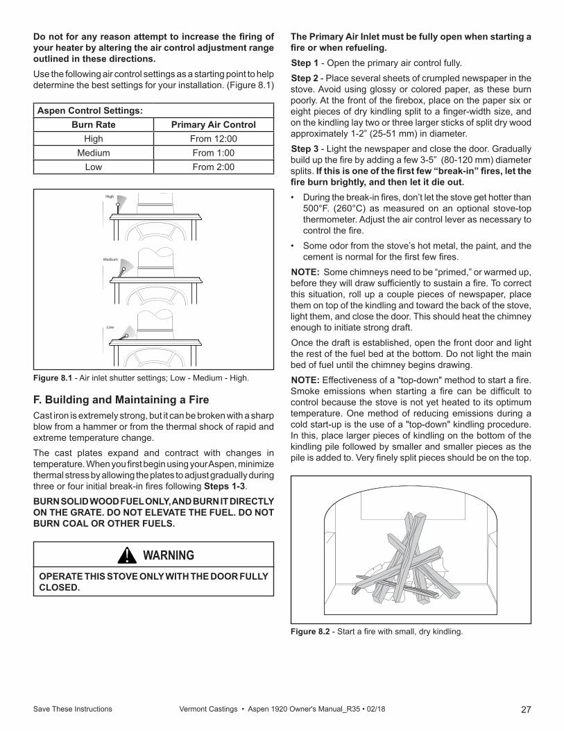
27Save These Instructions Vermont Castings • Aspen 1920 Owner's Manual_R35 • 02/18
High
ST262air inlet settings12/15/99 djt
Medium
Low
Figure 8.1 - Air inlet shutter settings; Low - Medium - High.
Aspen Control Settings:Burn Rate Primary Air Control
High From 12:00Medium From 1:00
Low From 2:00
The Primary Air Inlet must be fully open when starting a fire or when refueling. Step 1 - Open the primary air control fully.Step 2 - Place several sheets of crumpled newspaper in the stove. Avoid using glossy or colored paper, as these burn poorly. At the front of the firebox, place on the paper six or eight pieces of dry kindling split to a finger-width size, and on the kindling lay two or three larger sticks of split dry wood approximately 1-2” (25-51 mm) in diameter.Step 3 - Light the newspaper and close the door. Gradually build up the fire by adding a few 3-5” (80-120 mm) diameter splits. If this is one of the first few “break-in” fires, let the fire burn brightly, and then let it die out. • During the break-in fires, don’t let the stove get hotter than
500°F. (260°C) as measured on an optional stove-top thermometer. Adjust the air control lever as necessary to control the fire.
• Some odor from the stove’s hot metal, the paint, and the cement is normal for the first few fires.
NOTE: Some chimneys need to be “primed,” or warmed up, before they will draw sufficiently to sustain a fire. To correct this situation, roll up a couple pieces of newspaper, place them on top of the kindling and toward the back of the stove, light them, and close the door. This should heat the chimney enough to initiate strong draft. Once the draft is established, open the front door and light the rest of the fuel bed at the bottom. Do not light the main bed of fuel until the chimney begins drawing.NOTE: Effectiveness of a "top-down" method to start a fire. Smoke emissions when starting a fire can be difficult to control because the stove is not yet heated to its optimum temperature. One method of reducing emissions during a cold start-up is the use of a "top-down" kindling procedure. In this, place larger pieces of kindling on the bottom of the kindling pile followed by smaller and smaller pieces as the pile is added to. Very finely split pieces should be on the top.
Do not for any reason attempt to increase the firing of your heater by altering the air control adjustment range outlined in these directions.Use the following air control settings as a starting point to help determine the best settings for your installation. (Figure 8.1)
F. Building and Maintaining a FireCast iron is extremely strong, but it can be broken with a sharp blow from a hammer or from the thermal shock of rapid and extreme temperature change.The cast plates expand and contract with changes in temperature. When you first begin using your Aspen, minimize thermal stress by allowing the plates to adjust gradually during three or four initial break-in fires following Steps 1-3.BURN SOLID WOOD FUEL ONLY, AND BURN IT DIRECTLY ON THE GRATE. DO NOT ELEVATE THE FUEL. DO NOT BURN COAL OR OTHER FUELS.
ST263starting a fire12/99
Figure 8.2 - Start a fire with small, dry kindling.
WARNING!OPERATE THIS STOVE ONLY WITH THE DOOR FULLY CLOSED.
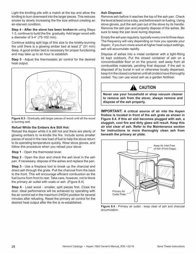
28 Save These Instructions Vermont Castings • Aspen 1920 Owner's Manual_R35 • 02/18
ST264good fire12/99
Figure 8.3 - Gradually add larger pieces of wood until all the wood is burning well.
Light the kindling pile with a match at the top and allow the kindling to burn downward into the larger pieces. This reduces smoke by slowly increasing the fire size without creating an air-starved condition.Step 4 - After the stove has been broken-in using Steps 1-3, continue to build the fire gradually. Add larger wood with a diameter of 3-4” (75-102 mm). Continue adding split logs of this size to the briskly-burning fire until there is a glowing ember bed at least 2” (51 mm) deep. A good ember bed is necessary for proper functioning and may take up to an hour to establish. Step 5 - Adjust the thermostatic air control for the desired heat output.
Ash Disposal:Remove ash before it reaches the top of the ash pan. Check the level at least once a day, and before each re-fueling. Using stove gloves, pull the ash pan out of the stove by its handle. Remove the ash pan and properly dispose of the ashes. Be sure to keep the pan level during disposal.Empty the ash pan regularly, typically every one to three days. The frequency will vary depending on how you operate your Aspen; if you burn more wood at higher heat output settings, ash will accumulate rapidly.Dispose of ashes into a metal container with a tight-fitting lid kept outdoors. Put the closed container of ash on a noncombustible floor or on the ground, well away from all combustible materials, pending final disposal. If the ash is disposed of by burial in soil or otherwise locally dispersed, keep it in the closed container until all cinders have thoroughly cooled. You can use wood ash as a garden fertilizer.
CAUTION!Never use your household or shop vacuum cleaner to remove ash from the stove; always remove and dispose of the ash properly.
Refuel While the Embers Are Still Hot:Reload the Aspen while it is still hot and there are plenty of glowing embers to re-kindle the fire. Include some smaller pieces of wood in the new load of fuel to help the stove return to its operating temperature quickly. Wear stove gloves, and follow this procedure when you reload your stove:Step 1 - Open the thermostat lever.Step 2 - Open the door and check the ash level in the ash pan. If necessary, dispose of the ashes and replace the pan.Step 3 - Use a fireplace tool to break up the charcoal and direct ash through the grate. Pull the charcoal from the back to the front. This will encourage efficient combustion as the fuel burns from front to rear. Take care, however, not to block the primary air outlet with coals or ash. (Figure 8.4)Step 4 - Load wood - smaller, split pieces first. Close the door. Ideal performance will be achieved by operating with the air control set in the maximum (HIGH) position for several minutes after refueling. Reset the primary air control for the desired heat output after the fire is re-established.
Figure 8.4 - Primary air outlet - keep clear of ash and charcoal accumulation.
Primary Air Outlet Plate
ST265ash pan12/99
Keep Air Inlet Free of Ash (Front Edge)
IMPORTANT: A critical source of air into the Aspen firebox is located in front of the ash grate as shown in Figure 8.4. If this air slot becomes plugged with ash, a sluggish, cool fire and dirty glass will result. Keep this air slot clear of ash. Refer to the Maintenance section for instructions to more thoroughly clean ash from beneath the primary air plate.
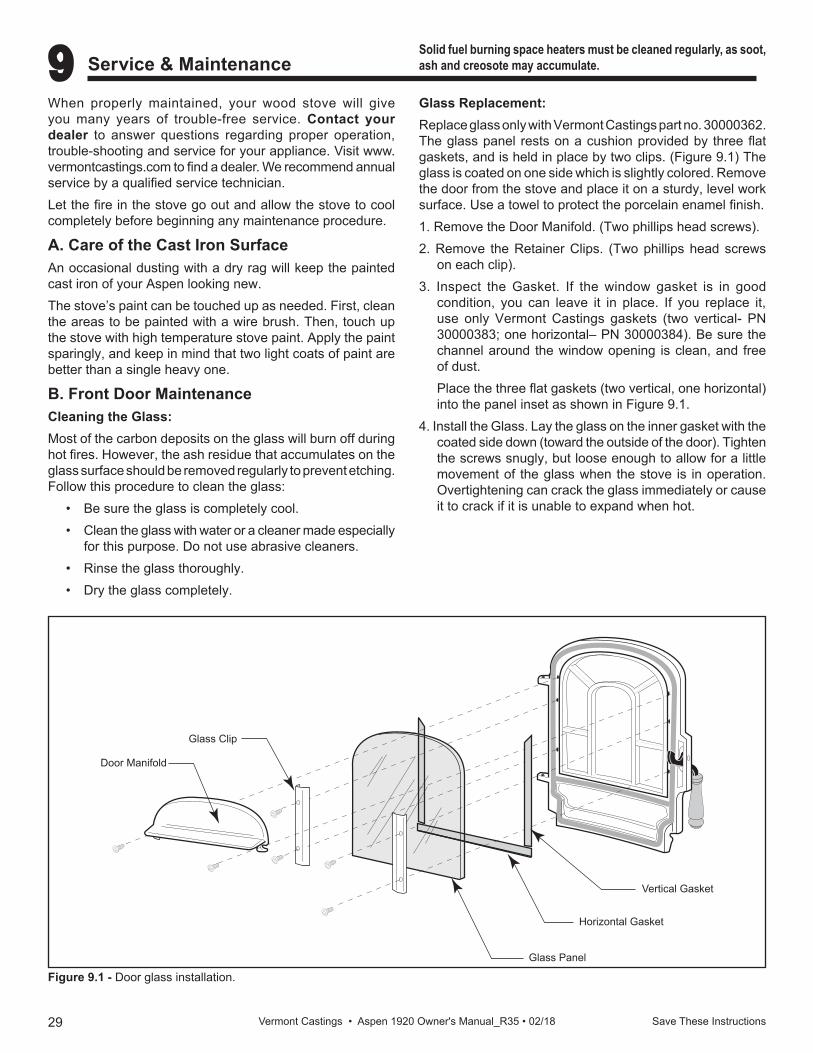
29 Save These Instructions Vermont Castings • Aspen 1920 Owner's Manual_R35 • 02/18
9 Service & Maintenance Solid fuel burning space heaters must be cleaned regularly, as soot, ash and creosote may accumulate.
When properly maintained, your wood stove will give you many years of trouble-free service. Contact your dealer to answer questions regarding proper operation, trouble-shooting and service for your appliance. Visit www.vermontcastings.com to find a dealer. We recommend annual service by a qualified service technician.Let the fire in the stove go out and allow the stove to cool completely before beginning any maintenance procedure.
A. Care of the Cast Iron SurfaceAn occasional dusting with a dry rag will keep the painted cast iron of your Aspen looking new. The stove’s paint can be touched up as needed. First, clean the areas to be painted with a wire brush. Then, touch up the stove with high temperature stove paint. Apply the paint sparingly, and keep in mind that two light coats of paint are better than a single heavy one.
B. Front Door MaintenanceCleaning the Glass:Most of the carbon deposits on the glass will burn off during hot fires. However, the ash residue that accumulates on the glass surface should be removed regularly to prevent etching. Follow this procedure to clean the glass:
• Be sure the glass is completely cool.• Clean the glass with water or a cleaner made especially
for this purpose. Do not use abrasive cleaners.• Rinse the glass thoroughly.• Dry the glass completely.
Glass Replacement:Replace glass only with Vermont Castings part no. 30000362. The glass panel rests on a cushion provided by three flat gaskets, and is held in place by two clips. (Figure 9.1) The glass is coated on one side which is slightly colored. Remove the door from the stove and place it on a sturdy, level work surface. Use a towel to protect the porcelain enamel finish.1. Remove the Door Manifold. (Two phillips head screws).2. Remove the Retainer Clips. (Two phillips head screws
on each clip).3. Inspect the Gasket. If the window gasket is in good
condition, you can leave it in place. If you replace it, use only Vermont Castings gaskets (two vertical- PN 30000383; one horizontal– PN 30000384). Be sure the channel around the window opening is clean, and free of dust.
Place the three flat gaskets (two vertical, one horizontal) into the panel inset as shown in Figure 9.1.
4. Install the Glass. Lay the glass on the inner gasket with the coated side down (toward the outside of the door). Tighten the screws snugly, but loose enough to allow for a little movement of the glass when the stove is in operation. Overtightening can crack the glass immediately or cause it to crack if it is unable to expand when hot.
ST348Aspendoor glass parts2/00
Door Manifold
Glass Clip
Glass Panel
Horizontal Gasket
Vertical Gasket
Figure 9.1 - Door glass installation.
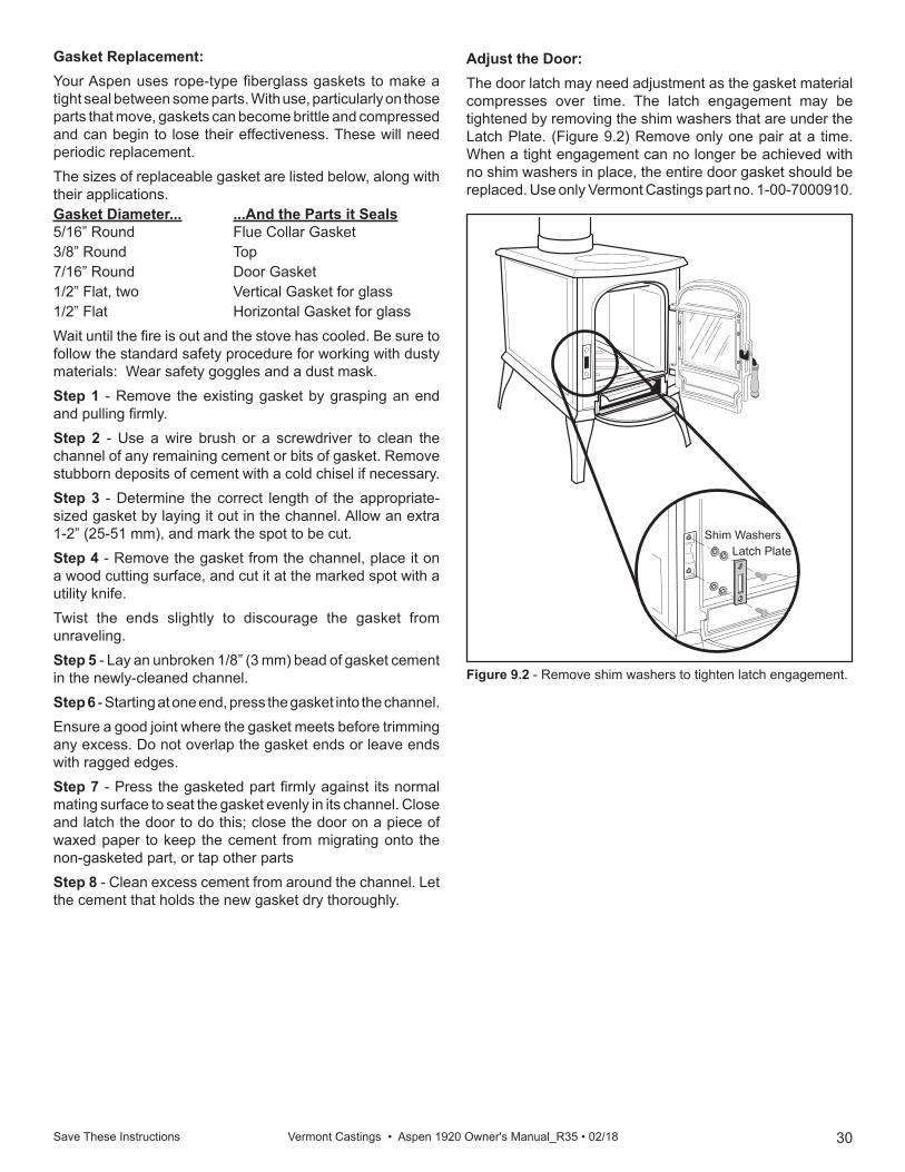
30Save These Instructions Vermont Castings • Aspen 1920 Owner's Manual_R35 • 02/18
ST267door latch12/99
ST268door latch detail12/99
Shim WashersLatch Plate
Figure 9.2 - Remove shim washers to tighten latch engagement.
Adjust the Door:The door latch may need adjustment as the gasket material compresses over time. The latch engagement may be tightened by removing the shim washers that are under the Latch Plate. (Figure 9.2) Remove only one pair at a time. When a tight engagement can no longer be achieved with no shim washers in place, the entire door gasket should be replaced. Use only Vermont Castings part no. 1-00-7000910.
Gasket Replacement:Your Aspen uses rope-type fiberglass gaskets to make a tight seal between some parts. With use, particularly on those parts that move, gaskets can become brittle and compressed and can begin to lose their effectiveness. These will need periodic replacement.The sizes of replaceable gasket are listed below, along with their applications.Gasket Diameter... ...And the Parts it Seals 5/16” Round Flue Collar Gasket 3/8” Round Top7/16” Round Door Gasket1/2” Flat, two Vertical Gasket for glass1/2” Flat Horizontal Gasket for glassWait until the fire is out and the stove has cooled. Be sure to follow the standard safety procedure for working with dusty materials: Wear safety goggles and a dust mask. Step 1 - Remove the existing gasket by grasping an end and pulling firmly.Step 2 - Use a wire brush or a screwdriver to clean the channel of any remaining cement or bits of gasket. Remove stubborn deposits of cement with a cold chisel if necessary.Step 3 - Determine the correct length of the appropriate-sized gasket by laying it out in the channel. Allow an extra 1-2” (25-51 mm), and mark the spot to be cut. Step 4 - Remove the gasket from the channel, place it on a wood cutting surface, and cut it at the marked spot with a utility knife. Twist the ends slightly to discourage the gasket from unraveling.Step 5 - Lay an unbroken 1/8” (3 mm) bead of gasket cement in the newly-cleaned channel.Step 6 - Starting at one end, press the gasket into the channel. Ensure a good joint where the gasket meets before trimming any excess. Do not overlap the gasket ends or leave ends with ragged edges.Step 7 - Press the gasketed part firmly against its normal mating surface to seat the gasket evenly in its channel. Close and latch the door to do this; close the door on a piece of waxed paper to keep the cement from migrating onto the non-gasketed part, or tap other partsStep 8 - Clean excess cement from around the channel. Let the cement that holds the new gasket dry thoroughly.
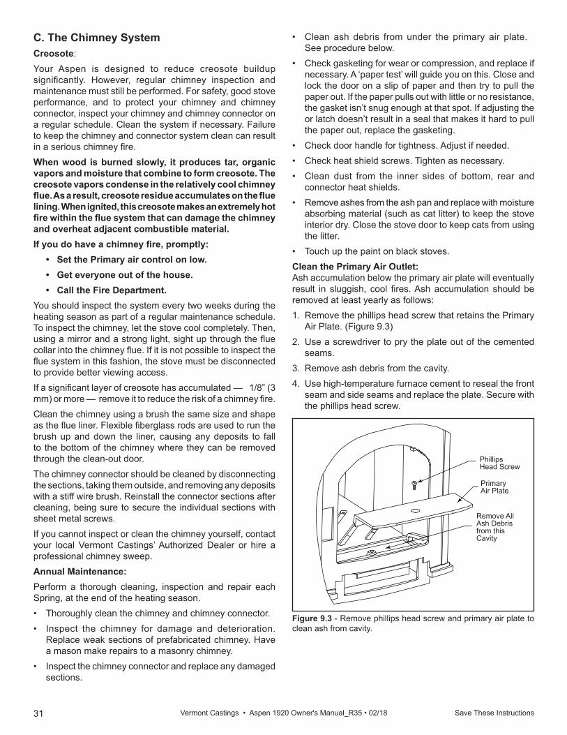
31 Save These Instructions Vermont Castings • Aspen 1920 Owner's Manual_R35 • 02/18
KT351cleaningprimary air11/02
Phillips Head Screw
Primary Air Plate
Remove All Ash Debris from this Cavity
Figure 9.3 - Remove phillips head screw and primary air plate to clean ash from cavity.
• Clean ash debris from under the primary air plate. See procedure below.
• Check gasketing for wear or compression, and replace if necessary. A ‘paper test’ will guide you on this. Close and lock the door on a slip of paper and then try to pull the paper out. If the paper pulls out with little or no resistance, the gasket isn’t snug enough at that spot. If adjusting the or latch doesn’t result in a seal that makes it hard to pull the paper out, replace the gasketing.
• Check door handle for tightness. Adjust if needed.• Check heat shield screws. Tighten as necessary.• Clean dust from the inner sides of bottom, rear and
connector heat shields.• Remove ashes from the ash pan and replace with moisture
absorbing material (such as cat litter) to keep the stove interior dry. Close the stove door to keep cats from using the litter.
• Touch up the paint on black stoves.Clean the Primary Air Outlet:Ash accumulation below the primary air plate will eventually result in sluggish, cool fires. Ash accumulation should be removed at least yearly as follows:1. Remove the phillips head screw that retains the Primary
Air Plate. (Figure 9.3)2. Use a screwdriver to pry the plate out of the cemented
seams.3. Remove ash debris from the cavity.4. Use high-temperature furnace cement to reseal the front
seam and side seams and replace the plate. Secure with the phillips head screw.
C. The Chimney SystemCreosote:Your Aspen is designed to reduce creosote buildup significantly. However, regular chimney inspection and maintenance must still be performed. For safety, good stove performance, and to protect your chimney and chimney connector, inspect your chimney and chimney connector on a regular schedule. Clean the system if necessary. Failure to keep the chimney and connector system clean can result in a serious chimney fire.When wood is burned slowly, it produces tar, organic vapors and moisture that combine to form creosote. The creosote vapors condense in the relatively cool chimney flue. As a result, creosote residue accumulates on the flue lining. When ignited, this creosote makes an extremely hot fire within the flue system that can damage the chimney and overheat adjacent combustible material.If you do have a chimney fire, promptly:
• Set the Primary air control on low.• Get everyone out of the house.• Call the Fire Department.
You should inspect the system every two weeks during the heating season as part of a regular maintenance schedule. To inspect the chimney, let the stove cool completely. Then, using a mirror and a strong light, sight up through the flue collar into the chimney flue. If it is not possible to inspect the flue system in this fashion, the stove must be disconnected to provide better viewing access. If a significant layer of creosote has accumulated — 1/8” (3 mm) or more — remove it to reduce the risk of a chimney fire.Clean the chimney using a brush the same size and shape as the flue liner. Flexible fiberglass rods are used to run the brush up and down the liner, causing any deposits to fall to the bottom of the chimney where they can be removed through the clean-out door. The chimney connector should be cleaned by disconnecting the sections, taking them outside, and removing any deposits with a stiff wire brush. Reinstall the connector sections after cleaning, being sure to secure the individual sections with sheet metal screws.If you cannot inspect or clean the chimney yourself, contact your local Vermont Castings’ Authorized Dealer or hire a professional chimney sweep.Annual Maintenance:Perform a thorough cleaning, inspection and repair each Spring, at the end of the heating season.• Thoroughly clean the chimney and chimney connector.• Inspect the chimney for damage and deterioration.
Replace weak sections of prefabricated chimney. Have a mason make repairs to a masonry chimney.
• Inspect the chimney connector and replace any damaged sections.
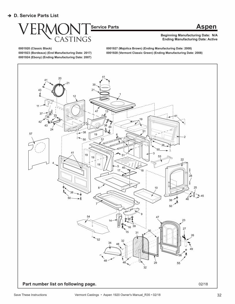
32Save These Instructions Vermont Castings • Aspen 1920 Owner's Manual_R35 • 02/18
D. Service Parts List
Service Parts
Beginning Manufacturing Date: N/A Ending Manufacturing Date: Active
Aspen
Part number list on following page. 02/18
0001920 (Classic Black) 0001927 (Majolica Brown) (Ending Manufacturing Date: 2008) 0001923 (Bordeaux) (End Manufacturing Date: 2017) 0001928 (Vermont Classic Green) (Ending Manufacturing Date: 2008) 0001924 (Ebony) (Ending Manufacturing Date: 2007)
1
19
1919
4
8
7
14
34
48
32
3248
48
31
47
30
29
49
26
27
23
52
16
15
39
38
9
1038
50
41
24
43
11
43
36
42
3733
21
12
41 20
19
50
38
47
21
35
41
13
4438
51
6
5
51
19
4017 18
3
51
38
41
2
50
53
38
50
22
28
45
25
46
54
55
56
57
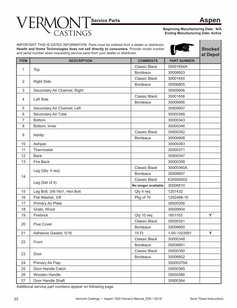
33 Save These Instructions Vermont Castings • Aspen 1920 Owner's Manual_R35 • 02/18
Service Parts
Beginning Manufacturing Date: N/A Ending Manufacturing Date: Active
Aspen
IMPORTANT: THIS IS DATED INFORMATION. Parts must be ordered from a dealer or distributor. Hearth and Home Technologies does not sell directly to consumers. Provide model number and serial number when requesting service parts from your dealer or distributor.
Stocked at Depot
ITEM DESCRIPTION COMMENTS PART NUMBER
1 TopClassic Black 30001654ABordeaux 30006803
2 Right SideClassic Black 30001655Bordeaux 30006805
3 Secondary Air Channel, Right 30000606
4 Left Side Classic Black 30001656Bordeaux 30006806
5 Secondary Air Channel, Left 300006076 Secondary Air Tube 300003687 Bottom 300003438 Bottom, Inner 30000346
9 AshlipClassic Black 30000352Bordeaux 30006808
10 Ashpan 3000036311 Thermostat 3000037112 Back 3000034713 Fire Back 30000358
14Leg (Qty. 4 req)
Classic Black 30000360ABordeaux 30006807
Leg (Set of 4)Classic Black K30000502
No longer available 3000681015 Leg Bolt, 3/8-16x1, Hex Bolt Qty 4 req 120143216 Flat Washer, 3/8 Pkg of 10 1202488-1017 Primary Air Plate 3000035618 Grate, Wood 3000060419 Firebrick Qty 10 req 1601103 Y
20 Flue CoverClassic Black 30000351Bordeaux 30006800
21 Adhesive Gasket, 5/16 15 Ft 1-00-1203591 Y
22 FrontClassic Black 30000348Bordeaux 30006801
23 DoorClassic Black 30000350Bordeaux 30006802
24 Primary Air Flap 30000370A25 Door Handle Catch 3000036526 Wooden Handle 3000036627 Door Handle Shaft 30000364
Additional service part numbers appear on following page.
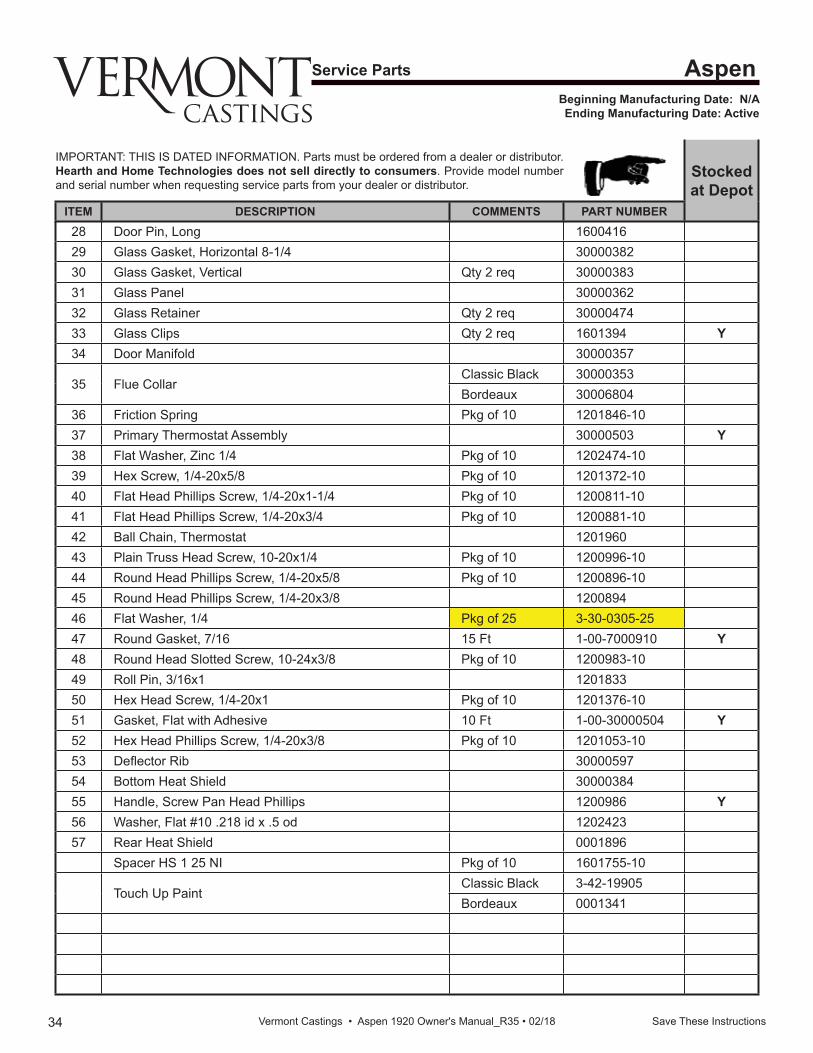
34 Save These Instructions Vermont Castings • Aspen 1920 Owner's Manual_R35 • 02/18
Service Parts
Beginning Manufacturing Date: N/A Ending Manufacturing Date: Active
Aspen
IMPORTANT: THIS IS DATED INFORMATION. Parts must be ordered from a dealer or distributor. Hearth and Home Technologies does not sell directly to consumers. Provide model number and serial number when requesting service parts from your dealer or distributor.
Stocked at Depot
ITEM DESCRIPTION COMMENTS PART NUMBER28 Door Pin, Long 160041629 Glass Gasket, Horizontal 8-1/4 3000038230 Glass Gasket, Vertical Qty 2 req 3000038331 Glass Panel 3000036232 Glass Retainer Qty 2 req 3000047433 Glass Clips Qty 2 req 1601394 Y34 Door Manifold 30000357
35 Flue CollarClassic Black 30000353Bordeaux 30006804
36 Friction Spring Pkg of 10 1201846-1037 Primary Thermostat Assembly 30000503 Y38 Flat Washer, Zinc 1/4 Pkg of 10 1202474-1039 Hex Screw, 1/4-20x5/8 Pkg of 10 1201372-1040 Flat Head Phillips Screw, 1/4-20x1-1/4 Pkg of 10 1200811-1041 Flat Head Phillips Screw, 1/4-20x3/4 Pkg of 10 1200881-1042 Ball Chain, Thermostat 120196043 Plain Truss Head Screw, 10-20x1/4 Pkg of 10 1200996-1044 Round Head Phillips Screw, 1/4-20x5/8 Pkg of 10 1200896-1045 Round Head Phillips Screw, 1/4-20x3/8 120089446 Flat Washer, 1/4 Pkg of 25 3-30-0305-2547 Round Gasket, 7/16 15 Ft 1-00-7000910 Y48 Round Head Slotted Screw, 10-24x3/8 Pkg of 10 1200983-1049 Roll Pin, 3/16x1 120183350 Hex Head Screw, 1/4-20x1 Pkg of 10 1201376-1051 Gasket, Flat with Adhesive 10 Ft 1-00-30000504 Y52 Hex Head Phillips Screw, 1/4-20x3/8 Pkg of 10 1201053-1053 De ector Rib 3000059754 Bottom Heat Shield 3000038455 Handle, Screw Pan Head Phillips 1200986 Y56 Washer, Flat #10 .218 id x .5 od 120242357 Rear Heat Shield 0001896
Spacer HS 1 25 NI Pkg of 10 1601755-10
Touch Up PaintClassic Black 3-42-19905Bordeaux 0001341
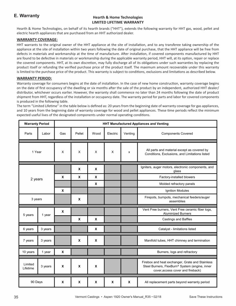
35 Save These Instructions Vermont Castings • Aspen 1920 Owner's Manual_R35 • 02/18
E. Warranty
4021-645J • 08-03-171
Hearth & Home TechnologiesLIMITED LIFETIME WARRANTY
Hearth & Home Technologies, on behalf of its hearth brands (“HHT”), extends the following warranty for HHT gas, wood, pellet and electric hearth appliances that are purchased from an HHT authorized dealer.
WARRANTY COVERAGE:HHT warrants to the original owner of the HHT appliance at the site of installation, and to any transferee taking ownership of the appliance at the site of installation within two years following the date of original purchase, that the HHT appliance will be free from defects in materials and workmanship at the time of manufacture. After installation, if covered components manufactured by HHT are found to be defective in materials or workmanship during the applicable warranty period, HHT will, at its option, repair or replace the covered components. HHT, at its own discretion, may fully discharge all of its obligations under such warranties by replacing the product itself or refunding the verified purchase price of the product itself. The maximum amount recoverable under this warranty is limited to the purchase price of the product. This warranty is subject to conditions, exclusions and limitations as described below.
WARRANTY PERIOD:Warranty coverage for consumers begins at the date of installation. In the case of new home construction, warranty coverage begins on the date of first occupancy of the dwelling or six months after the sale of the product by an independent, authorized HHT dealer/distributor, whichever occurs earlier. However, the warranty shall commence no later than 24 months following the date of product shipment from HHT, regardless of the installation or occupancy date. The warranty period for parts and labor for covered components is produced in the following table.The term “Limited Lifetime” in the table below is defined as: 20 years from the beginning date of warranty coverage for gas appliances, and 10 years from the beginning date of warranty coverage for wood and pellet appliances. These time periods reflect the minimum expected useful lives of the designated components under normal operating conditions.
Parts Labor Gas Pellet Wood Electric Venting Components Covered
X X Igniters, auger motors, electronic components, and glass
X X X Factory-installed blowers
X Molded refractory panels
X Ignition Modules
X Firepots, burnpots, mechanical feeders/auger assemblies
X Vent Free burners, Vent Free ceramic fiber logs, Aluminized Burners
X X Castings and Baffles
6 years 3 years X Catalyst - limitations listed
7 years 3 years X X Manifold tubes, HHT chimney and termination
10 years 1 year X Burners, logs and refractory
Limited Lifetime 3 years X X X
Firebox and heat exchanger, Grate and Stainless Steel Burners, FlexBurn® System (engine, inner
cover,access cover and fireback)
X X X X X All replacement parts beyond warranty period
Warranty Period HHT Manufactured Appliances and Venting
All parts and material except as covered by Conditions, Exclusions, and Limitations listedX X X
2 years
3 years
1 Year
90 Days
5 years 1 year
xX
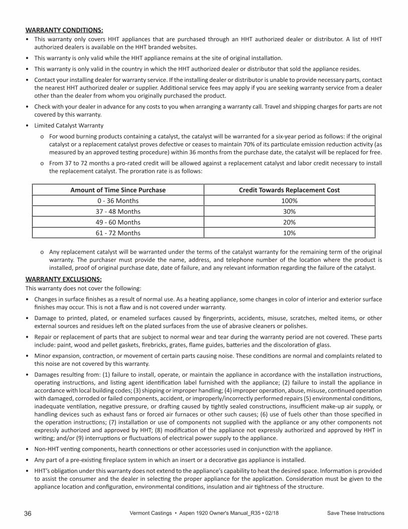
36 Save These Instructions Vermont Castings • Aspen 1920 Owner's Manual_R35 • 02/184021-645J • 08-03-172
WARRANTY CONDITIONS:• This warranty only covers HHT appliances that are purchased through an HHT authorized dealer or distributor. A list of HHT
authorized dealers is available on the HHT branded websites.
• This warranty is only valid while the HHT appliance remains at the site of original installation.
• This warranty is only valid in the country in which the HHT authorized dealer or distributor that sold the appliance resides.
• Contact your installing dealer for warranty service. If the installing dealer or distributor is unable to provide necessary parts, contact the nearest HHT authorized dealer or supplier. Additional service fees may apply if you are seeking warranty service from a dealer other than the dealer from whom you originally purchased the product.
• Check with your dealer in advance for any costs to you when arranging a warranty call. Travel and shipping charges for parts are not covered by this warranty.
• Limited Catalyst Warranty
o For wood burning products containing a catalyst, the catalyst will be warranted for a six-year period as follows: if the original catalyst or a replacement catalyst proves defective or ceases to maintain 70% of its particulate emission reduction activity (as measured by an approved testing procedure) within 36 months from the purchase date, the catalyst will be replaced for free.
o From 37 to 72 months a pro-rated credit will be allowed against a replacement catalyst and labor credit necessary to install the replacement catalyst. The proration rate is as follows:
Amount of Time Since Purchase Credit Towards Replacement Cost0 - 36 Months 100%
37 - 48 Months 30%49 - 60 Months 20%61 - 72 Months 10%
o Any replacement catalyst will be warranted under the terms of the catalyst warranty for the remaining term of the original warranty. The purchaser must provide the name, address, and telephone number of the location where the product is installed, proof of original purchase date, date of failure, and any relevant information regarding the failure of the catalyst.
WARRANTY EXCLUSIONS:This warranty does not cover the following:
• Changes in surface finishes as a result of normal use. As a heating appliance, some changes in color of interior and exterior surface finishes may occur. This is not a flaw and is not covered under warranty.
• Damage to printed, plated, or enameled surfaces caused by fingerprints, accidents, misuse, scratches, melted items, or other external sources and residues left on the plated surfaces from the use of abrasive cleaners or polishes.
• Repair or replacement of parts that are subject to normal wear and tear during the warranty period are not covered. These parts include: paint, wood and pellet gaskets, firebricks, grates, flame guides, batteries and the discoloration of glass.
• Minor expansion, contraction, or movement of certain parts causing noise. These conditions are normal and complaints related to this noise are not covered by this warranty.
• Damages resulting from: (1) failure to install, operate, or maintain the appliance in accordance with the installation instructions, operating instructions, and listing agent identification label furnished with the appliance; (2) failure to install the appliance in accordance with local building codes; (3) shipping or improper handling; (4) improper operation, abuse, misuse, continued operation with damaged, corroded or failed components, accident, or improperly/incorrectly performed repairs (5) environmental conditions, inadequate ventilation, negative pressure, or drafting caused by tightly sealed constructions, insufficient make-up air supply, or handling devices such as exhaust fans or forced air furnaces or other such causes; (6) use of fuels other than those specified in the operation instructions; (7) installation or use of components not supplied with the appliance or any other components not expressly authorized and approved by HHT; (8) modification of the appliance not expressly authorized and approved by HHT in writing; and/or (9) interruptions or fluctuations of electrical power supply to the appliance.
• Non-HHT venting components, hearth connections or other accessories used in conjunction with the appliance.
• Any part of a pre-existing fireplace system in which an insert or a decorative gas appliance is installed.
• HHT’s obligation under this warranty does not extend to the appliance’s capability to heat the desired space. Information is provided to assist the consumer and the dealer in selecting the proper appliance for the application. Consideration must be given to the appliance location and configuration, environmental conditions, insulation and air tightness of the structure.
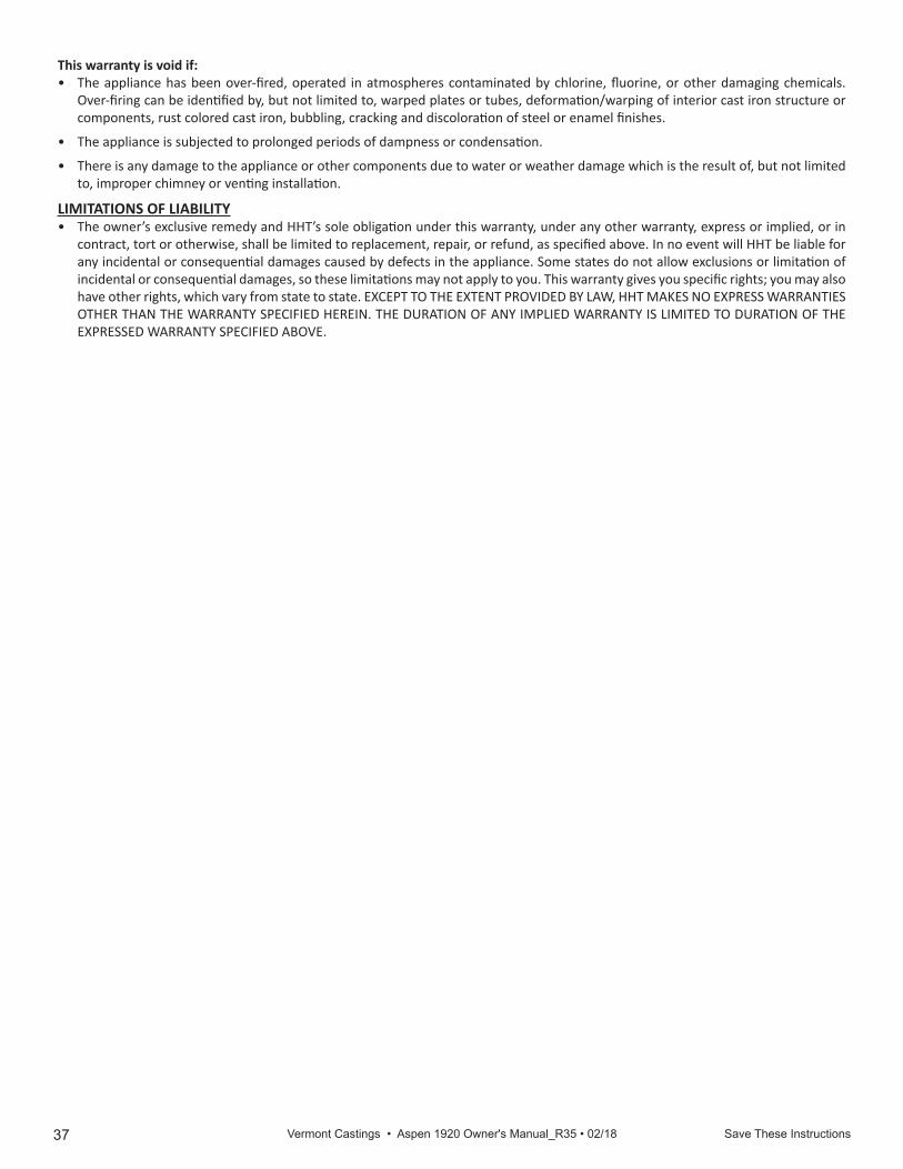
37 Save These Instructions Vermont Castings • Aspen 1920 Owner's Manual_R35 • 02/18 4021-645J • 08-03-173
This warranty is void if:• The appliance has been over-fired, operated in atmospheres contaminated by chlorine, fluorine, or other damaging chemicals.
Over-firing can be identified by, but not limited to, warped plates or tubes, deformation/warping of interior cast iron structure or components, rust colored cast iron, bubbling, cracking and discoloration of steel or enamel finishes.
• The appliance is subjected to prolonged periods of dampness or condensation.
• There is any damage to the appliance or other components due to water or weather damage which is the result of, but not limited to, improper chimney or venting installation.
LIMITATIONS OF LIABILITY• The owner’s exclusive remedy and HHT’s sole obligation under this warranty, under any other warranty, express or implied, or in
contract, tort or otherwise, shall be limited to replacement, repair, or refund, as specified above. In no event will HHT be liable for any incidental or consequential damages caused by defects in the appliance. Some states do not allow exclusions or limitation of incidental or consequential damages, so these limitations may not apply to you. This warranty gives you specific rights; you may also have other rights, which vary from state to state. EXCEPT TO THE EXTENT PROVIDED BY LAW, HHT MAKES NO EXPRESS WARRANTIES OTHER THAN THE WARRANTY SPECIFIED HEREIN. THE DURATION OF ANY IMPLIED WARRANTY IS LIMITED TO DURATION OF THE EXPRESSED WARRANTY SPECIFIED ABOVE.

38 Save These Instructions Vermont Castings • Aspen 1920 Owner's Manual_R35 • 02/18
352 Mountain House Road • Halifax, PA 17032www.vermontcastings.com