Embed Size (px)
Citation preview

VENTILATION SYSTEMS
INSTALLATION AND OPERATING
TECHNICAL MANUAL
FOR ADDITIONAL COPIES VISIT OUR WEB SITE AT www.avtecind.com
AVTEC INDUSTRIES INC. 120 KENDALL POINT DR. OSWEGO, IL 60543-8898 630-851-4800
TABLE OF CONTENTS
I. TYPES OF SYSTEMS 1 A. Baffle Filter . .. . . . . . . . . . . . . . . . . . . . . . . . . . . . . . . . . . . . . . . . . . . . . . . . . . . 1 B. Modular Grease Extractors [Energy Aire] . . . . . . . . . . . . . . . . . . . . . . . . . . . . . . . 1 C. Auto Wash [Energy Aire] . . . . . . . . . . . . . . . . . . . . . . . . . . . . . . . . . . . . . . . . . . . 1 D. Airflow Requirements . . . . . . . . . . . . . . . . . . . . . . . . . . . . . . . . . . . . .. . . . . . . . . . 2 E. Fire Extinguishing Systems .. . . . . . . . . . . . . . . . . . . . . . . . . . . . . . . . . . . . . . . . . . 2
II. INSTALLING THE VENTILATOR . . . . . . . . . . . . . . . . . . . . . . . . . . . . . . . . . . . . . . . . 2/3
III. CONTROL PANEL . . . . . . . . . .. . . . . . . . . . . . . . . . . . . . . . . . . . . . . . . . . . . . . . . . . . 3 A. Wall Attachment . . . . . . . . . . . . . . . . . . . . . . . . . . . . . . . . . . . . . . . . . . . . . . . . . . 3
IV. ELECTRICAL CONNECTIONS . . . . . . . . . . . . . . . . . . . . . . . . . . . . . . . . . . . . . . . . . 5 A. VCW Control Panel . . . . . . . . . . . . . . . . . . . . . . . . . . . . . . . . . . . . . . . . . . . . . . . . 5 B. PAWS Control Panel . . . . . . . . . . .. . . . . . . . . . . . . . . . . . . . . . . . . . . . . . . . . . . . . 5/6/7 C. Damper and Detectors . . . . . . . . . . . . . . . . . . . . . . . . . . . . . . . . . . . . . . . . . . . . . 9 D. Ventilator Lights . . . . . . . . . . . . . . . . . . . . . . . . . . . . . . . . . . . . . . . . . . . . . . . . . . 9
V. PLUMBING CONNECTIONS . . . . . . . . . . . . . . . . . . . . . . . . . . . . . . . . . . . . . . . . . . . 9 A. Hot Water Wash . . . . . . . . . . . . . . . . . . . . . . . . . . . . . . . . . . . . . . . . . . . . . . . . . 9 B. Cold Water Mist [optional] . . . . . . . . . . . . . . . . . . . . . . . . . . . . . . . . . . . . . . . . . . . 9 C. Drains . . . . . . . . . . . . . . . . . . . . . . . . . . . . . . . . . . . . . . . . . . . . . . . . . . . . . . . . . . 9 D. Field Joints . . . . . . . . . . . . . . . . . . . . . . . . . . . . . . . . . . . . . . . . . . . . . . . . . . . . . 9 E. Detergent Pump and Tank . . . . . . . . . . . . . . . . . . . . . . . . . . . . . . . . . . . . . . . . . . 9 F. Interconnecting . . . . . . . . . . . . . . . . . . . . . . . . . . . . . . . . . . . . . . . . . . . . . . . . . . . 9 G. Detergent Flow Chart . . . . . . . . . .. . . . . . . . . . . . . . . . . . . . . . . . . . . . . . . . . . . . . 10
VI. OPERATION . . . . . . . . . . . . . . . . . . . . . . . . . . . . . . . . . . . . . . . . . . . . . . . . . . . . . . . 11 A. VCW Control Panel . . . . . . . . . . . . . . . . . . . . . . . . . . . . . . . . . . . . . . . . . . . . . . . . 11 1. Adjustment . . . . . . . . . . .. . . . . . . . . . . . . . . . . . . . . . . . . . . . . . . . . . . . . . . . . . 11 2. Sequence Of Operation . . . . . . . . . . . . . . . . . . . . . . . . . . . . . . . . . . . . . . . . . . 11 3. Trouble-Shooting . . . . . . . . . .. . . . . . . . . . . . . . . . . . . . . . . . . . . . . . . . . . . . . . 11/12 B. PAWS Control Panel . . . . . . . . . . . . . . . . . . . . . . . . . . . . . . . . . . . . . . . . . . . . . . . 12/13 1. Manual Operation . . . . . . . . . . . . . . . . . . . . . . . . . . . . . . . . . . . . . . . . . . . . . . . . 12/13 a. Fan Start . . . . . . . . . . . . . . . . . . . . . . . . . . . . . . . . . . . . . . . . . . . . . . . . . . . . 13 b. Fan Stop . . . . . . . . . . . . . . . . . . . . . . . . . . . . . . . . . . . . . . . . . . . . . . . . . . . . 13 c. Wash Start . . . . . . . . . . . . . . . . . . . . . . . . . . . . . . . . . . . . . . . . . . . . . . . . . . 13 d. Wash Stop . . . . . . . . . . . . . . . . . . . . . . . . . . . . . . . . . . . . . . . . . . . . . . . . . . . 13 2. Trouble Conditions . . . . . . . . . . . . . . . . . . . . . . . . . . . . . . . . . . . . . . . . . . . . . . . 13 a. Low Detergent Indicator . . . . . . . . . . . . . . . . . . . . . . . . . . . . . . . . . . . . . . . . 13 b. Supervised Valve [optional] . . . . . . . . . .. . . . . . . . . . . . . . . . . . . . . . . . . . . . . 13 3. Hood Plenum Fire Protection . . . . . . . . . . . . . . . . . . . . . . . . . . . . . . . . . . . . . . . 13 a. Automatic Operation . . . . . . . . . . . . . . . . . . . . . . . . . . . . . . . . . . . . . . . . . . . 13 b. Manual Operation . . . . . . . . . . . . . . . . . . . . . . . . . . . . . . . . . . . . . . . . . . . . . . 13 4. Programming Instructions . . . . . . . . . . . . . . . . . . . . . . . . . . . . . . . . . . . . . . . . . 13/14 a . Setting The Clock . . . . . . . . . . . . . . . . . . . . . . . . . . . . . . . . . . . . . . . . . . . . . . 13/14 b. Setting The PAWS . . . . . . . . . . . . . . . . . . . . . . . . . . . . . . . . . . . . . . . . . . . . . 14 1. Single Wash Models . . . . . . . . . . . . . . . . . . . . . . . . . . . . . . . . . . . . . . . . . . 14 2. Multi-Wash Models . . . . . . . . . . . . . . . . . . . . . . . . . . . . . . . . . . . . . . . . . . . 14 c. Setting The Fire Delay . . . . . . . . . .. . . . . . . . . . . . . . . . . . . . . . . . . . . . . . . . . 14 d. Reviewing The Daily Event Schedule . . . . . . . . . . . . . . . . . . . . . . . . . . . . . . . 15 e. Changing The Daily Event Schedule . . . . . . . . . . . . . . . . . . . . . . . . . . . . . . . 15 f. Repeating The Daily Event Schedule . . . . . . . .. . . . . . . . . . . . . . . . . . . . . . . 15 g. Holiday Feature . . . . . . . . . . . . . . . . . . . . . . . . . . . . . . . . . . . . . . . . . . . . . . . 15 h. Fan On During Recovery . . . . . . . . . . . . . . . . . . . . . . . . . . . . . . . . . . . . . . . . 16 i. Power Loss . . . . . . . . . . . . . . . . . . . . . . . . . . . . . . . . . . . . . . . . . . . . . . . . . . 16 j. Last Command Indicator . . . . . . . . . . . . . . . . . . . . . . . . . . . . . . . . . . . . . . . . 16 k. Diagnostic Indicators . . . . . . . . . . . . . . . . . . . . . . . . . . . . . . . . . . . . . . . . . . 16 l. Detergent Pump and Tank . . . . . . . . . . . . . . . . . . . . . . . . . . . . . . . . . . . . . . . . 18
VII. VENTILATOR FEATURES AND ACCESSORIES . . . . . . . . . . . . . . . . . . . . . . . . . . . 18 A. Baffle Filter . . . . . . . . . . . . . . . . . . . . . . . . . . . . . . . . . . . . . . . . . . . . . . . . . . . . . . . 18 B. Modular Grease Extractors . . . . . . . . . . . . . . . . . . . . . . . . . . . . . . . . . . . . . . . . . . 18 C. Auto Wash Grease Extractors . . . . . . . . . . . . . . . . . . . . . . . . . . . . . . . . . . . . . . . . 19 D. Air Adjustment Baffle . . . . . . . . . . . . . . . . . . . . . . . . . . . . . . . . . . . . . . . . . . . . . . . 19 E. Fire Dampers . . . . . . . . . . . . . . . . . . . . . . . . . .. . . . . . . . . . . . . . . .. .. . . . . . . .. .. . 20 F. Air Make-Up [Supply] Plenums . . . . . . . . . . . . . . . . . . . . . . . . . . . . . . . . . . . . .. .. . 20 G. Auto Wash . . . . . . . . . . . . . . . . . . . . . . . . . . . . . . . . . . . . . . . . . . . . . . . . . . . . . . 21 H. Cold Water Mist [Optional] . . . . . . . . . . . . . . . . . . . . . . . . . . . . . . . . . . . . . . . . . . 21 I. Lights . . . . . . . . . . . . . . . . . . . . . . . . . . . . . . . . . . . . . . . . . . . . . . . . . . . . . . . . . . 21
VIII. PERIODIC MAINTENANCE . . . . . . . . .. . . . . . . . . . . . . . . . . . . . . . . . . . . . . . . . . . . . 21 A. Baffle Filters . . . . . . . . . . . . . . . . . . . . . . . . . . . . . . . . . . . . . . . . . . . . . . . . . . . . . . 21 B. Modular Grease Extractors . . . . . . . . . . . . . . . . . . . . . . . . . . . . . . . . . . . . . . . . . . 21 C. Grease Trough . . . . . . . . . . . . . . . . . . . . . . . . . . . . . . . . . . . . . . . . . . . . . . . . . . . 21 D. Grease Collection Receptacle . . . . . . . . . . . . . . . . . . . . . . . . . . . . . . . . . . . . . . . . 22 E. Hood Canopy . . . . . . . . . . . . . . . . . . . . . . . . . . . . . . . . . . . . . . . . . . . . . . . . . . . . . 22 F. Detergent System . . . . . . . . . . . . . . . . . . . . . . . . . . . . . . . . . . . . . . . . . . . . . . . . . 22 G. Fusible Link Replacement . . . . . . . . . . . . . . . . . . . . . . . . . . . . . . . . . . . . . . . . . . 22
IX. PARTS LIST A. PAWS Panel - Electrical . . . . . . . . . . . . . . . . . . . . . . . . . . . . . . . . . . . . . . . . . . . . 23 B. VCW Panel - Electrical . . . . . . . . . . . . . . . . . . . . . . . . . . . . . . . . . . . . . . . . . . . . 23 C. PAWS/VCW Panel - Plumbing . . . . . . . . . . . . . . . . . . . . . . . . . . . . . . . . . . . . . . 23 D. EVAC Detergent . . . . . . . . . . . . . . . . . . . . . . . . . . . . . . . . . . . . . . . . . . . . . . . . . . 24 E. Electro-Mechanical Damper . . . . . . . . . . . . . . . . . . . . . . . . . . . . . . . . . . . . . . . . . 24 F. Fusible Link Damper . . . . . . . . . . . . . . . . . . . . . . . . . . . . . . . . . . . . . . . . . . . . . . . 25 G. Hood Canopy . . . . . . . . . . . . . . . . . . . . . . . . . . . . . . . . . . . . . . . . . . . . . . . . . . . 25/26
X. OTHER DATA AND DRAWINGS A. EVAC Cleaner Cut Sheet . . . . . . . . . . . . . . . . . . . . . . . . . . . . . . . . . . . . . . . . . . . 27 B. Air Movement Recordings . . . . . . . . . . . . . . . . . . . . . . . . . . . . . . . . . . . . . . . . . . 28 C. Calculating and Recording Air Movement Readings . . . . . . . . . . . . . . . . . . . . . . 29 D. Calculating and Recording Air Movement . . . . . . . . . . . . . . . . . . . . . . . . . . . . . . 30
XI. WARRANTY . . . . . . . . . . . . . . . . . . . . . . . . . . . . . . . . . . . . . . . . . . . . . . . . . . . . . . . 31

1
1I. TYPES OF SYSTEMS This manual covers three [3] of the basic types of
systems offered by AVTEC - Baffle Filter [AF], Modular Grease Extractor [AX] and Auto Wash Down [AW].
A.Baffle Filter [AF Series] [See fig. #1]
Model AF ventilators are listed by Underwriters Laboratories Inc. [UL] and are built in accordance with the National Fire Protection Association [NFPA] Standard No. 96 for use with UL Listed fire extinguishing systems for duct hood protection. They are available with or without an automatic exhaust fire damper. They utilize UL Classified removable baffle filters to extract grease and provide a limited fire barrier. The canopy contains an integral grease trough and removable grease receptacle(s). Surface, plenum and duct collar fire extinguishing systems may be factory supplied. Vent Control Panels may be supplied with these systems. See additional wiring diagrams for options.
Installation shall be in accordance with NFPA 96.
B.Modular Grease Extractors [AX Series] Energy Aire [see fig. #2] Model AX ventilators are listed by UL and built in accordance with NFPA Standard No. 96 for use with UL Listed fire extinguishing systems for duct and hood protection. They are available with or without an automatic exhaust fire damper.
These models utilize high velocity removable grease extractors. This exclusive design extracts up to 95%* of airborne grease contaminants. The
1 *Data from independent tests not a part of UL test procedure.
canopy contains an integral grease trough and grease collection receptacle(s). Surface, plenum and duct collar fire extinguishing systems are
required and may be factory supplied.
Vent control panels may be supplied with these systems. See additional wiring diagrams for options.
Installation shall be in accordance with NFPA 96.
C.Auto Wash Down [AW Series] Energy Aire [see
fig. #3] Model AW ventilators are listed by UL and built in
accordance with NFPA Standard No. 96 for use with UL Listed fire extinguishing systems for duct and hood protection. They are available with or without an automatic exhaust fire damper.
These systems utilize a high velocity grease extractor. This exclusive design extracts up to 95%* of airborne grease contaminants. An

2
integral water wash system cleans the inside of the grease extraction chamber either by manual activation of the Wash Start button or by a programmable timer. The duration of the wash is electrically controlled. The wash system is also activated by an electrical thermostat or a manual switch in the event of a fire condition. A surface fire extinguishing system is required and may be factory supplied. Auto Wash control panels are provided with these systems. Wiring diagrams are provided with this manual.
Installation shall be in accordance with NFPA 96.
D.Airflow Requirements Minimum exhaust airflow requirements and
maximum make-up airflow requirements [where air is introduced directly inside the canopy] are shown on the chart below. These flow rates were established under laboratory conditions. Greater exhaust airflows and/or reduced make-up airflows may be required for complete capture.
CFM REQUIREMENTS 400°F Cooking 600°F Cooking 700°F Cooking Model No. Surface Equip. Surface Equip. Surface Equip. AFWO,AFBO 200 300 525 AFDO,AFWP AFBP,AFDP AFWE,AFDE AFBE AFWI,AFBI 250[175] N/R N/R AFDI,AFWD AFBD,AFDD AFIO,AFIP 250 400 600 AFIE AFII,AFID 300[150] N/R N/R AXWO,AXBO 200 275 525 AXDO,AXWP AXBP,AXDP AXWE,AXDE AXBE AXWI,AXBI 250[175] N/R N/R AXDI,AXWD AXBD,AXDD AXIO,AXIP 250 400 600 AXII 300[150] N/R N/R AWWO,AWWP 194 270 *525 AWWE,AWDO AWDP,AWDE AWBO,AWBP AWBE AWWI,AWBI 250[190] 270[146] N/R AWDI,AWWD AWBD,AWDD AWTE,AWTP 400 420 N/R AWTO N/R = Not Recommended *=Manufacturer's test results not yet submitted to U.L. for capture tests.
E.Fire Extinguishing Systems There are two basic types of ventilator fire extinguishing systems in use today:
Wet Chemical and Water Mist. Wet Chemical Systems may be all or partially factory installed [by the Fire System Manufacturer]; final hook up and certification at job site is done by the Fire System Manufacturer's local representative. These systems must be periodially inspected, and critical parts replaced. It is suggested that a service contract be purchased from the local representative. For further details refer to the manufacturer's technical manual.
AVTEC manufactures and installs a water mist fire extinguishing system, "MIST-A-FIRE", that connects to the building fire sprinkler system [must be "wet" type system]. Final connect of this system must be done in the field by the sprinkler contractor or authorized plumber. A certification/inspection report is done by an authorized AVTEC representative. Periodic inspection is generally required, but replacement of parts and periodic maintenance is virtually eliminated. For further details, refer to the AVTEC MIST-A-FIRE Installation and Operating Technical Manual.
II. INSTALLING THE VENTILATOR
The ventilator is supplied with brackets to facilitate the attachment of hanger rods to the vent. Hanger rods should be attached to all brackets to ensure proper support.
A.Ascertain that the ceiling/roof structure is strong enough to support the weight of the hood and support system. The approximate weight of the hood is shown below:
45 lbs/linear ft. for hoods w/o AMU plenums. 55 lbs/linear ft. for hoods w/AMU plenums. 125 lbs for fire control cabinet.
B.Carefully uncrate the hood so as not to dent or scratch the outer surface.
C.Position the hood on the floor in approximately its final installed location.
D.Use 1/2" threaded rods to hang the hood. The hanger rods should be approximately 1/2" closer to the wall at the structural attachment location than at the top of the hood. [see fig. #4] This ensures that the hood is held tightly against the wall.
Note! Do not remove Support Brace until Ventilator installation is complete. Upon completion of installation, dispose of Support Brace and replace the Acorn Nuts to their original locations.
Error! Not a valid link.
Fig 4
E.The hood should be hung so that the bottom of the hood is 6'-6" above the finished floor unless otherwise specified. Carefully lift the hood into position being certain to avoid scratching the finished surfaces.

3
Install 1/2" threaded rod from each bracket and the structural support. Secure rods with heavy duty nuts. [see fig. #5] Be sure that the hood is level.
Error! Not a valid link. Fig 5
Tower Interface Detail Place trim collar on tower. Position tower under hood. Fully tighten trim collar retainer hardware after tower and hood are aligned properly. See fig. A, B, and C (next page).
F.The entire exhaust duct system must be con-
tinuously welded. This includes the connection to the duct collar and the roof curb. All welds must be liquid tight.
NOTE: Welds must not impede operation of damper.
G.Connect the lights to the circuit breaker panel
through the light switch. All connections should be in compliance with NFPA 70, National Electric Code [NEC].
H. Install bulbs in the light fixture[s].
I.Install the grease filters [AF] or modules [AX].
J.Install the grease receptacles [AF or AX]
NOTE: A minimum of a three inch [3"] insulated fire barrier and air space must be maintained between the capture area skin of the ventilator and any combustible surface, including wall and ceiling. AVTEC ventilators normally have a 3" air space; insulation is added when specified.
III.CONTROL PANEL [if provided]
Control panels are provided with all auto wash type ventilators [Models AW- ] and are optional with the baffle filter type [AF- ] and modular grease extractor type [AX- ]. Control panels with Models AF- and AX- do not have the auto wash plumbing assembly compartments. Any control panel may be provided with a integral MIST-A- FIRE Extinguishing System alarm panel and sprinkler assembly piping; refer to the MIST-A-FIRE technical manual. A.Wall Attachment
Control panel dimensions and connection detail are shown on the enclosed shop drawing. Panels may be surface mounted, partially recessed or fully recessed as shown on fig. 6. 1.Surface Mounted
Drill four [4] holes in ventilator plumbing compartment as required. Be careful not to damage any components. Avoid drilling into electrical compartments. Bolt to wall with anchor bolts or other acceptable means. Weight of control panel varies from 90 lbs. to 200 lbs.
2.Recessed Cut hole in wall 1/2" greater than O/A dimensions of control box [shown on shop drawing]. Spacers or support angles may be necessary to provide proper support. It is recommended that panel be bolted to wall similar to method used for surface mounted above.

4
5
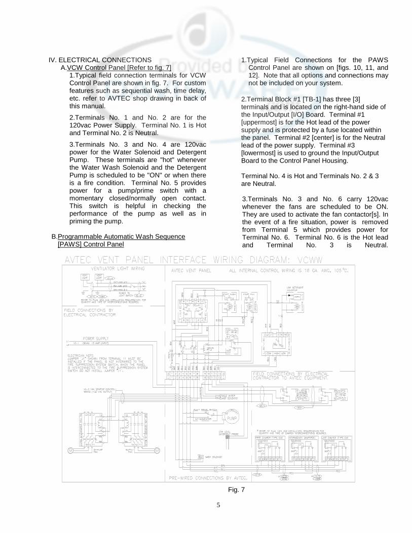
IV. ELECTRICAL CONNECTIONS A.VCW Control Panel [Refer to fig. 7]
1.Typical field connection terminals for VCW Control Panel are shown in fig. 7. For custom features such as sequential wash, time delay, etc. refer to AVTEC shop drawing in back of this manual.
2.Terminals No. 1 and No. 2 are for the 120vac Power Supply. Terminal No. 1 is Hot and Terminal No. 2 is Neutral.
3.Terminals No. 3 and No. 4 are 120vac power for the Water Solenoid and Detergent Pump. These terminals are "hot" whenever the Water Wash Solenoid and the Detergent Pump is scheduled to be "ON" or when there is a fire condition. Terminal No. 5 provides power for a pump/prime switch with a momentary closed/normally open contact. This switch is helpful in checking the performance of the pump as well as in priming the pump.
B.Programmable Automatic Wash Sequence
[PAWS] Control Panel
1.Typical Field Connections for the PAWS Control Panel are shown on [figs. 10, 11, and 12]. Note that all options and connections may not be included on your system.
2.Terminal Block #1 [TB-1] has three [3] terminals and is located on the right-hand side of the Input/Output [I/O] Board. Terminal #1 [uppermost] is for the Hot lead of the power supply and is protected by a fuse located within the panel. Terminal #2 [center] is for the Neutral lead of the power supply. Terminal #3 [lowermost] is used to ground the Input/Output Board to the Control Panel Housing. Terminal No. 4 is Hot and Terminals No. 2 & 3 are Neutral.
3.Terminals No. 3 and No. 6 carry 120vac whenever the fans are scheduled to be ON. They are used to activate the fan contactor[s]. In the event of a fire situation, power is removed from Terminal 5 which provides power for Terminal No. 6. Terminal No. 6 is the Hot lead and Terminal No. 3 is Neutral.
Fig. 7

6
4.Terminal Block #2 [TB-2] has three [3] pairs of terminals and is located at the upper right corner of the Input/Output Board. The first pair of terminals are for the number one wash valve solenoid. This will be the only wash output active in a P-10-__ or P-15-__ Control Panel. The second pair of terminals are for the number two wash valve solenoid. The third pair of terminals are for the number three wash valve solenoid.
5.Terminal Block #3 [TB-3] has three [3] pairs of
terminals. It will not be present on P-10-__ or P-15-__ Control Panels. The first pair of terminals are for wash valve solenoid number four. The second pair of terminals are for the number five wash valve solenoid. The third pair of terminals are for the number six wash valve solenoid.
6.Terminal Block #4 [TB-4] has three [3] pairs of
terminals. It will not be present on P-10-__ or P-15-__ Control Panels. The first pair of terminals are for the number seven wash valve solenoid. The second pair of terminals are for the number eight wash valve solenoid.
7.Terminal Block #5 [TB-5] has three [3] pairs of
terminals. The first pair provides power for the detergent pump. The second pair provides power for the PAWS Alarm/Trouble horn. [The third pair provides power for the vent fan contactors. [see figs. #8a & 8b]
Note that the maximum output is one-and-one-half [1-1/2] amperes. If the total inrush current for all contactors will exceed this limit, an intermediate relay must be used. 8.Terminal Block #9 [TB-9] has three [3] pairs of terminals and is located at the lower left corner of the Input/Output Board. The first pair of terminals are for connection to the optional supervised shut-off valve. If the panel is not equipped with this option, a jumper wire must be installed. The second pair of terminals are for connection to the Manual Fire Switch. The third pair of terminals are for connection to the automatic fire switch contacts terminals are for connection to the automatic fire switch contacts.
Fig 8a
Fig 8b
7
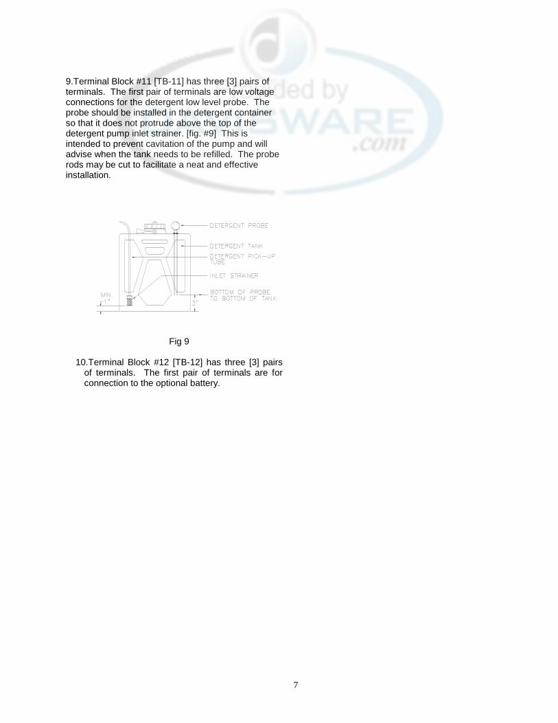
9.Terminal Block #11 [TB-11] has three [3] pairs of terminals. The first pair of terminals are low voltage connections for the detergent low level probe. The probe should be installed in the detergent container so that it does not protrude above the top of the detergent pump inlet strainer. [fig. #9] This is intended to prevent cavitation of the pump and will advise when the tank needs to be refilled. The probe rods may be cut to facilitate a neat and effective installation.
Fig 9
10.Terminal Block #12 [TB-12] has three [3] pairs
of terminals. The first pair of terminals are for connection to the optional battery.
8
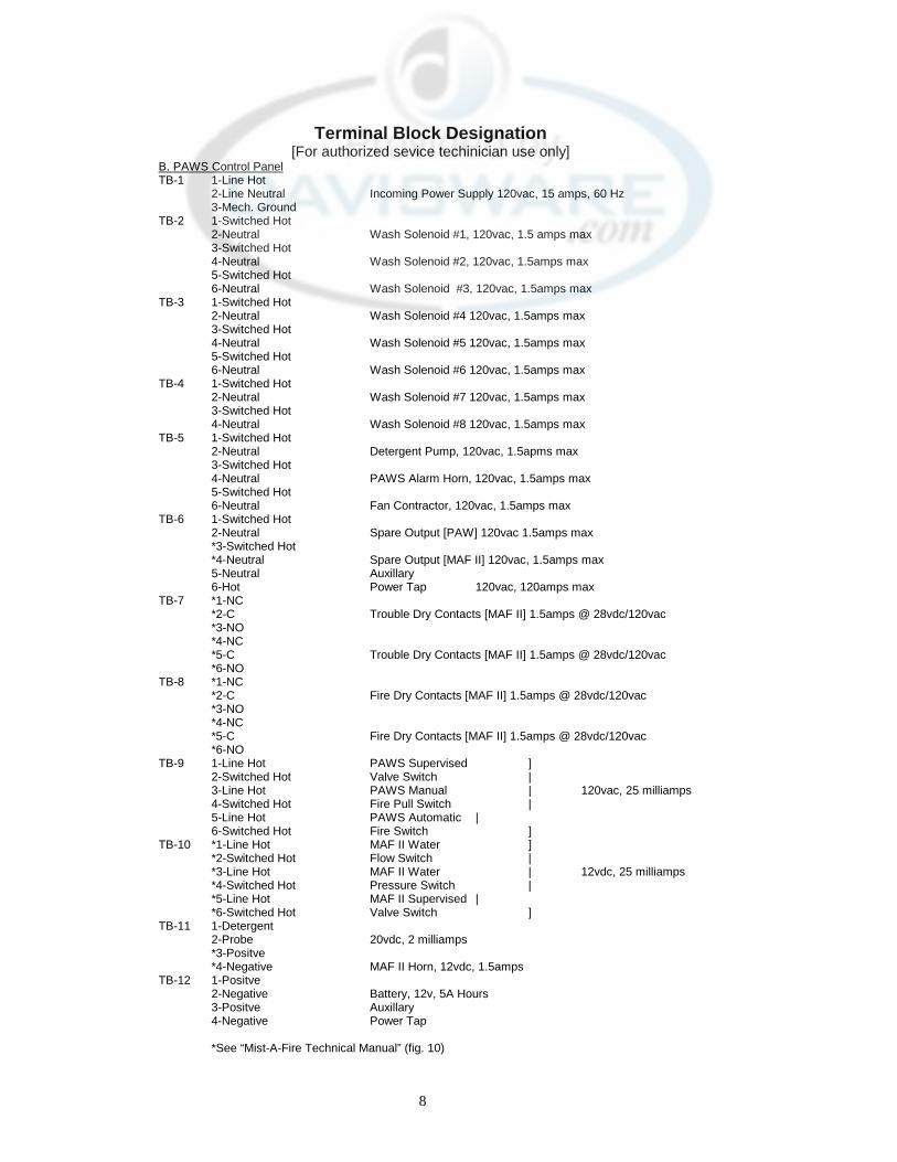
Terminal Block Designation [For authorized sevice techinician use only]
B. PAWS Control Panel TB-1 1-Line Hot 2-Line Neutral Incoming Power Supply 120vac, 15 amps, 60 Hz 3-Mech. Ground TB-2 1-Switched Hot 2-Neutral Wash Solenoid #1, 120vac, 1.5 amps max 3-Switched Hot 4-Neutral Wash Solenoid #2, 120vac, 1.5amps max 5-Switched Hot 6-Neutral Wash Solenoid #3, 120vac, 1.5amps max TB-3 1-Switched Hot 2-Neutral Wash Solenoid #4 120vac, 1.5amps max 3-Switched Hot 4-Neutral Wash Solenoid #5 120vac, 1.5amps max 5-Switched Hot 6-Neutral Wash Solenoid #6 120vac, 1.5amps max TB-4 1-Switched Hot 2-Neutral Wash Solenoid #7 120vac, 1.5amps max 3-Switched Hot 4-Neutral Wash Solenoid #8 120vac, 1.5amps max TB-5 1-Switched Hot 2-Neutral Detergent Pump, 120vac, 1.5apms max 3-Switched Hot 4-Neutral PAWS Alarm Horn, 120vac, 1.5amps max 5-Switched Hot 6-Neutral Fan Contractor, 120vac, 1.5amps max TB-6 1-Switched Hot 2-Neutral Spare Output [PAW] 120vac 1.5amps max *3-Switched Hot *4-Neutral Spare Output [MAF II] 120vac, 1.5amps max 5-Neutral Auxillary 6-Hot Power Tap 120vac, 120amps max TB-7 *1-NC *2-C Trouble Dry Contacts [MAF II] 1.5amps @ 28vdc/120vac *3-NO *4-NC *5-C Trouble Dry Contacts [MAF II] 1.5amps @ 28vdc/120vac *6-NO TB-8 *1-NC *2-C Fire Dry Contacts [MAF II] 1.5amps @ 28vdc/120vac *3-NO *4-NC *5-C Fire Dry Contacts [MAF II] 1.5amps @ 28vdc/120vac *6-NO TB-9 1-Line Hot PAWS Supervised ] 2-Switched Hot Valve Switch | 3-Line Hot PAWS Manual | 120vac, 25 milliamps 4-Switched Hot Fire Pull Switch | 5-Line Hot PAWS Automatic | 6-Switched Hot Fire Switch ] TB-10 *1-Line Hot MAF II Water ] *2-Switched Hot Flow Switch | *3-Line Hot MAF II Water | 12vdc, 25 milliamps *4-Switched Hot Pressure Switch | *5-Line Hot MAF II Supervised | *6-Switched Hot Valve Switch ] TB-11 1-Detergent 2-Probe 20vdc, 2 milliamps *3-Positve *4-Negative MAF II Horn, 12vdc, 1.5amps TB-12 1-Positve 2-Negative Battery, 12v, 5A Hours 3-Positve Auxillary 4-Negative Power Tap *See “Mist-A-Fire Technical Manual” (fig. 10)
9
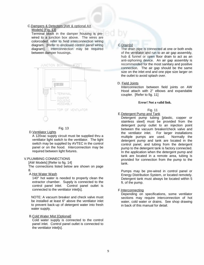
C.Dampers & Detectors [AW & optional AX Models] [Fig. 13]
Terminal block in the damper housing is pre-wired to a junction box above. The wires are colorcoded; refer to field interconnection wiring diagram. [Refer to enclosed control panel wiring diagram]. Interconnection may be required between damper housings.
Fig. 13
D.Ventilator Lights A 120vac supply circuit must be supplied thru a ventilator light switch to the ventilator. The light switch may be supplied by AVTEC in the control panel or on the hood. Interconnection may be required between light fixtures.
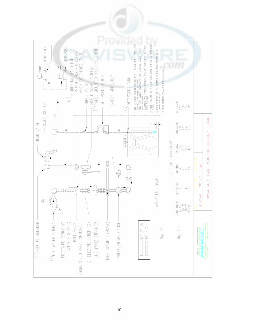
V.PLUMBING CONNECTIONS
[AW Models] [Refer to fig. 14] The connections listed below are shown on page 8. A.Hot Water Wash
140° hot water is needed to properly clean the extractor chamber. Supply is connected to the control panel inlet. Control panel outlet is connected to the ventilator inlet[s].
NOTE: A vacuum breaker and check valve must be installed at least 6" above the ventilator inlet to prevent back-up of detergent water into fresh water supply.
B.Cold Water Mist [Optional]
Cold water supply is connected to the control panel inlet. Control panel outlet is connected to the ventilator inlet[s].
C.Drain[s]
The drain pipe is connected at one or both ends of the ventilator and run to an air gap assembly, hub & funnel or open floor drain to act as an anti-siphoning device. An air gap assembly is recommended for the most sanitary and positive connection. The air gap should be the same size on the inlet end and one pipe size larger on the outlet to avoid splash over.
D. Field Joints Interconnection between field joints on AW
Hood attach with 2” elbows and expandable coupler. [Refer to fig. 11]
Error! Not a valid link.
Fig. 11
E.Detergent Pump and Tank Detergent pump tubing [plastic, copper or stainless steel] must be provided from the detergent pump outlet to an injection point between the vacuum breaker/check valve and the ventilator inlet. For larger installations multiple pumps are used. Normally the detergent pump and tank are located in the control panel, and tubing from the detergent pump to the detergent tank is factory connected. In the application when the detergent pump and tank are located in a remote area, tubing is provided for connection from the pump to the tank.
Pumps may be pre-wired in control panel or Energy Distribution System, or located remotely. Detergent tank must always be located within 5 ft. of the pump.
F.Interconnecting
Depending on specifications, some ventilator sections may require interconnection of hot water, cold water or drains. See shop drawing in back of this manual for detail.
10
11
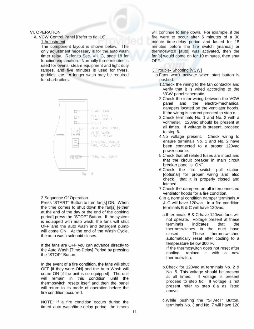
VI. OPERATION A. VCW Control Panel [Refer to fig. 16]
1.Adjustment The component layout is shown below. The only adjustment necessary is for the auto wash timer relay. Refer to Sec. VII. G, page 18 for function explanation. Normally three minutes is used for ovens, steam equipment and light duty ranges, and five minutes is used for fryers, griddles, etc. A longer wash may be required for charbroilers.
2.Sequence Of Operation Press "START" Button to turn fan[s] ON. When the time comes to shut down the fan[s] [either at the end of the day or the end of the cooking period] press the "STOP" Button. If the system is equipped with auto wash, the fans will shut OFF and the auto wash and detergent pump will come ON. At the end of the Wash Cycle, the auto wash solenoid closes.
If the fans are OFF you can advance directly to the Auto Wash [Time-Delay] Period by pressing the "STOP" Button.
In the event of a fire condition, the fans will shut OFF [if they were ON] and the Auto Wash will come ON [if the unit is so equipped]. The unit will remain in this condition until the thermoswitch resets itself and then the panel will return to its mode of operation before the fire condition occurred.
NOTE: If a fire condition occurs during the timed auto wash/time-delay period, the timers
will continue to time down. For example, if the fire were to occur after 5 minutes of a 30 minute time-delay period and lasted for 15 minutes before the fire switch [manual] or thermoswitch [auto] was activated, then the fan[s] would come on for 10 minutes, then shut OFF.
3.Trouble- Shooting [VCW]
a.Fans won't activate when start button is pushed. 1.Check the wiring to the fan contactor and
verify that it is wired according to the VCW panel schematic.
2.Check the inter-wiring between the VCW panel and the electro-mechanical dampers located on the ventilator hoods. If the wiring is correct proceed to step c.
3.Check terminals No. 1 and No. 2 with a voltmeter. 120vac should be present at all times. If voltage is present, proceed to step 6.
4.No voltage present. Check wiring to ensure terminals No. 1 and No. 2 have been connected to a proper 120vac power source.
5.Check that all related fuses are intact and that the circuit breaker in main circuit breaker panel is "ON".
6.Check the fire switch pull station [optional] for proper wiring and also check that it is properly closed and latched.
7.Check the dampers on all interconnected ventilator hoods for a fire condition.
8.In a normal condition damper terminals A & C will have 120vac. In a fire condition terminals B & C will have 120vac.
a.If terminals B & C have 120vac fans will not operate. Voltage present at these terminals indicates that the thermoswitches in the duct have closed. These thermoswitches automatically reset after cooling to a temperature below 300°F. If the thermoswitch does not reset after cooling, replace it with a new thermoswitch.
b.Check for 120vac at terminals No. 2 &
No. 5. This voltage should be present at all times. If voltage is present proceed to step 8c. If voltage is not present refer to step 8.a as listed above.
c.While pushing the "START" Button,
terminals No. 3 and No. 7 will have 120
12
vac as long as the "START" Button is depressed.
d.Once the "Start" Button is released, power[120vac] will be present at terminals No. 2 & No. 6. If no power is present after releasing start button verify that the fan contactor has been wired as shown on VCW Panel Electrical Schematic.
e.Voltage present at terminals No. 2 & No. 6 after pushing "START" Button, fans won't operate. This condition indicates that the control wiring is operating properly, therefore the problem must be in the fan motor itself or the power supply wiring to fan thru the normally open contactor or the fan contactor.
b.Auto Wash Solenoid does not open.
1.Check that fuse is intact. 2.Check terminals No. 1 and No. 2 with volt
meter. a.If 120vac proceed to step 2d. b.If no voltage, check fuse and wiring to
panel. c.Check panel circuit breaker and verify
that it is "ON", d.Press "Stop" button in completely and
hold for one [1] full second. e.Check terminals No. 3 and No. 4 with
volt meter. i.If 120vac is present, check wiring to
water solenoid. Check voltage at solenoid coil. If 120vac is present, replace coil. If no voltage, refer to step 2.b.
ii.Check the timer relay inside the VCW Panel to verify that power is going thru the contacts and that the coil is engaging. If relay doesn't function properly, replace the relay, If relay functions properly proceed to step 4.
iii.Check wiring against schematic to verify that is correct. Check condition of wires and connections to verify that they are not loose or damaged.
c. Auto Wash Solenoid will not close.
1.Check terminals No. 3 & No. 4 for voltage [120vac]. If no voltage is present proceed to step e.
2.Check the wiring to the fire switch pull station to see that it has been wired to the correct contacts.
3.Check the fire switch pull station [optional] to verify it has not been pulled.
4.Check all the dampers on the ventilator to verify that none of the dampers have been activated into the fire condition.
5.Check condition of solenoid for damage or debris.
d.Solenoid coil activates but no water flow is
present. 1.Check water pressure gauge. If water
pressure of 25 psig or more is present proceed to steps 2 & 3. If no water pressure is present proceed to steps 4 & 5.
2.Check solenoid valve for damage or debris.
3.Check for water line blockage and verify all spray nozzles are clear.
4.Check all water supply valves to verify they are open.
5.Check and clean all line wye strainers.
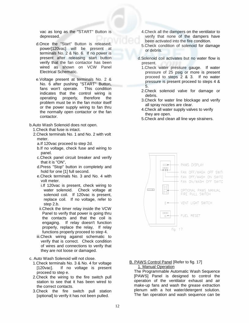
B. PAWS Control Panel [Refer to fig. 17]
1. Manual Operation The Programmable Automatic Wash Sequence [PAWS] Panel is designed to control the operation of the ventilator exhaust and air make-up fans and wash the grease extraction plenum with a hot water/detergent solution. The fan operation and wash sequence can be
13
started and stopped manually or programmed or automatic operation. a. Fan Start The exhaust and air make-up fans can be started manually by pressing "FAN ON/WASH OFF" on the PAWS panel. If the wash cycle is in progress it will stop immediately and the fans will start. The PAWS display will indicate "FAN ON/WASH OFF". b. Fan Stop The exhaust and air make-up fans can be stopped manually by pressing "FAN OFF/WASH OFF" on the PAWS panel. The fans will stop immediately. The PAWS display will indicate "FAN OFF/WASH OFF".
c. Wash Start The wash cycle can be started manually by pressing "FAN OFF/WASH ON'' on the PAWS panel. If the fans are on, they will stop immediately. The display will indicate "WASH 1" and the total time [in hours and minutes] remaining until the wash cycle ends.
d. Wash Stop The wash cycle can be stopped manually by pressing "FAN OFF/WASH OFF" on the PAWS panel. The wash cycle will stop immediately. The PAWS display will read "FAN OFF/WASH OFF".
2. Trouble Conditions
a. Low Detergent Indicator If the detergent level drops below the bottom of the detergent probe, the PAWS panel horn will sound and the display will flash "DETERGENT LOW". The horn can be silenced by pressing the "VFC Horn Silence" switch, but the trouble condition will continue to be displayed. The detergent pump will not operate until the detergent tank is refilled. The fan and wash cycles will continue to operate normally, however, the display will continue to flash "LOW DETERGENT". When the detergent tank is refilled, the trouble condition will automatically clear itself after approximately 10 seconds.
b. Supervised Water Valve [optional] If your PAWS panel is equipped with the optional supervised valve, the PAWS panel horn will sound and the display will flash "PLENUM WASH AND FIRE CYCLES LOST" when the valve is closed. The horn can be
silenced by pressing the "VFC Horn Silence" switch, but the trouble condition will continue to be displayed. The fan will operate normally, hot water will not flow during the wash cycle and the display will continue to flash "PLENUM WASH AND FIRE CYCLES LOST". When the valve is opened, the alarm condition will automatically clear itself. In the event that the detergent level drops below the probe and the optional supervised valve is closed at the same time, the horn will sound and the display will alternate between "DETERGENT LOW" and "PLENUM WASH AND FIRE CYCLES LOST". The horn can be silenced by pressing the "VFC Horn Silence " switch.
3. Hood Plenum Fire Protection
a. Automatic Operation In the event of a fire in and/or under the ventilator, the fans will turn off and the plenum wash will be activated when the temperature at the duct collar exceeds 300°F. The display will read "AUTO FIRE CYCLE FAN OFF/WASH ON" and the PAWS panel alarm will sound. The alarm cannot be silenced. When the temperature at the duct collar drops below 300°F, the PAWS panel will enter the fire delay cycle. During the fire delay cycle the fan will remain off and the hood plenum wash will remain on for a programmable period of time then automatically return to normal operation. The fire delay cycle can be terminated by pressing "FAN OFF/WASH OFF" on the PAWS panel. [See Sec. 4.b.2.c for setting Fire Delay Cycle Duration].
b. Manual Operation The PAWS panel may be equipped with the optional "Manual Fire Switch". Pulling the "Manual Fire Switch" will turn on the exhaust fan(s) and activate the plenum hood wash to act as a fire barrier. The display will read "MAN'L FIRE CYCLE FAN ON/WASH ON" and the PAWS panel alarm will sound. The alarm cannot be silenced. After the "Manual Fire Switch" is reset, the PAWS panel will enter the fire delay cycle. During the fire delay cycle the exhaust fan will remain on for a programmable period of time then automatically return to normal operation. The fire delay cycle can be terminated by pressing "FAN OFF/WASH OFF" on the PAWS panel. [See Sec. 4.3 for setting Fire Delay Cycle duration].
4. Programming Instructions [Refer to fig. 17A & 17B] a. Setting the Clock
14
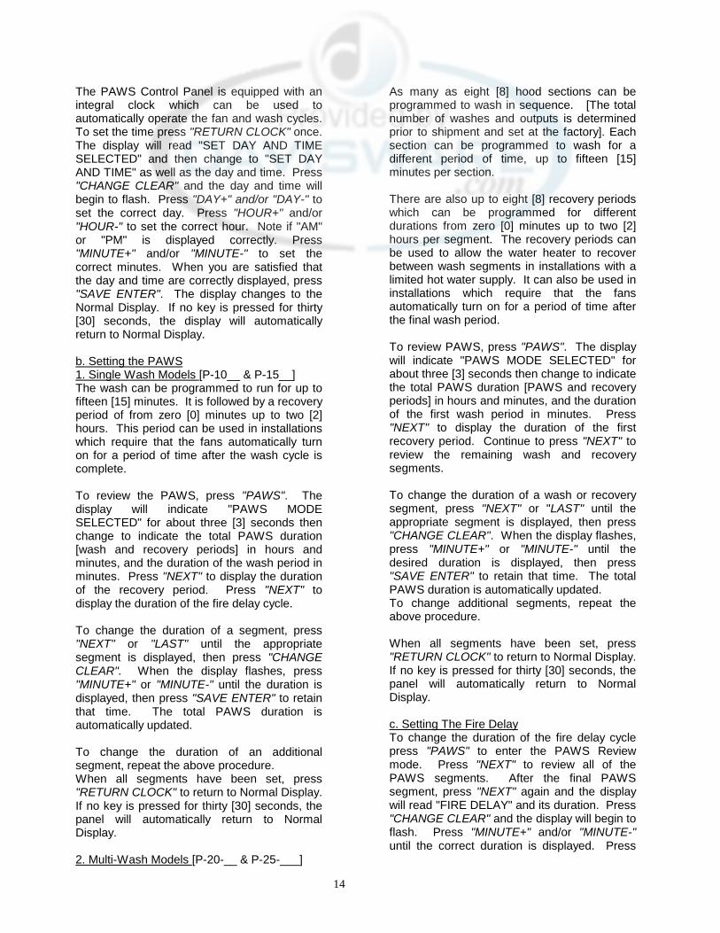
The PAWS Control Panel is equipped with an integral clock which can be used to automatically operate the fan and wash cycles. To set the time press "RETURN CLOCK" once. The display will read "SET DAY AND TIME SELECTED" and then change to "SET DAY AND TIME" as well as the day and time. Press "CHANGE CLEAR" and the day and time will begin to flash. Press "DAY+" and/or "DAY-" to set the correct day. Press "HOUR+" and/or "HOUR-" to set the correct hour. Note if "AM" or "PM" is displayed correctly. Press "MINUTE+" and/or "MINUTE-" to set the correct minutes. When you are satisfied that the day and time are correctly displayed, press "SAVE ENTER". The display changes to the Normal Display. If no key is pressed for thirty [30] seconds, the display will automatically return to Normal Display.
b. Setting the PAWS 1. Single Wash Models [P-10__ & P-15__] The wash can be programmed to run for up to fifteen [15] minutes. It is followed by a recovery period of from zero [0] minutes up to two [2] hours. This period can be used in installations which require that the fans automatically turn on for a period of time after the wash cycle is complete.
To review the PAWS, press "PAWS". The display will indicate "PAWS MODE SELECTED" for about three [3] seconds then change to indicate the total PAWS duration [wash and recovery periods] in hours and minutes, and the duration of the wash period in minutes. Press "NEXT" to display the duration of the recovery period. Press "NEXT" to display the duration of the fire delay cycle. To change the duration of a segment, press "NEXT" or "LAST" until the appropriate segment is displayed, then press "CHANGE CLEAR". When the display flashes, press "MINUTE+" or "MINUTE-" until the duration is displayed, then press "SAVE ENTER" to retain that time. The total PAWS duration is automatically updated.
To change the duration of an additional segment, repeat the above procedure. When all segments have been set, press "RETURN CLOCK" to return to Normal Display. If no key is pressed for thirty [30] seconds, the panel will automatically return to Normal Display.
2. Multi-Wash Models [P-20-__ & P-25-___]
As many as eight [8] hood sections can be programmed to wash in sequence. [The total number of washes and outputs is determined prior to shipment and set at the factory]. Each section can be programmed to wash for a different period of time, up to fifteen [15] minutes per section.
There are also up to eight [8] recovery periods which can be programmed for different durations from zero [0] minutes up to two [2] hours per segment. The recovery periods can be used to allow the water heater to recover between wash segments in installations with a limited hot water supply. It can also be used in installations which require that the fans automatically turn on for a period of time after the final wash period.
To review PAWS, press "PAWS". The display will indicate "PAWS MODE SELECTED" for about three [3] seconds then change to indicate the total PAWS duration [PAWS and recovery periods] in hours and minutes, and the duration of the first wash period in minutes. Press "NEXT" to display the duration of the first recovery period. Continue to press "NEXT" to review the remaining wash and recovery segments.
To change the duration of a wash or recovery segment, press "NEXT" or "LAST" until the appropriate segment is displayed, then press "CHANGE CLEAR". When the display flashes, press "MINUTE+" or "MINUTE-" until the desired duration is displayed, then press "SAVE ENTER" to retain that time. The total PAWS duration is automatically updated. To change additional segments, repeat the above procedure.
When all segments have been set, press "RETURN CLOCK" to return to Normal Display. If no key is pressed for thirty [30] seconds, the panel will automatically return to Normal Display.
c. Setting The Fire Delay To change the duration of the fire delay cycle press "PAWS" to enter the PAWS Review mode. Press "NEXT" to review all of the PAWS segments. After the final PAWS segment, press "NEXT" again and the display will read "FIRE DELAY" and its duration. Press "CHANGE CLEAR" and the display will begin to flash. Press "MINUTE+" and/or "MINUTE-" until the correct duration is displayed. Press

15
"SAVE ENTER" to retain that time. Press "RETURN CLOCK" to return to Normal Display.
d. Reviewing The Daily Event Schedule The Daily Event Schedule is a program which will automatically turn the fans on and off and/or initiate the PAWS up to four [4] times each day. Each day may be different from another or it may be programmed to stay off for the entire day. To review the Daily Event Schedule, press "CHECK". The display will show "CHECK MODE SELECTED" and then indicate the first programmed event of that day. If there are no events programmed for that day, it will display the next programmed event. If there are entries in the Daily Event Schedule, press "NEXT" to see the next event and/or press "LAST" to see the previous event. Press "RETURN CLOCK" to return to Normal Display. If no key is pressed for thirty [30] seconds the display will automatically change to Normal Display.
e. Changing The Daily Event Schedule In order to make initial entires in the Daily Event Schedule or change existing entries, press "PROGRAM DAY". The display will show "PROGRAM MODE SELECTED" then ask which day's events are to be changed. Press "DAY+" and/or "DAY-" to select the desired day, then press "SAVE ENTER". If no events are programmed to occur that day, the display will indicate "FAN ON UNPROG". If events are programmed for the day selected, that day's first event will be displayed. If an event other than the one being displayed is to be entered or changed, press "NEXT" until the correct event is displayed. Press "CHANGE CLEAR".
NOTE: WHEN AN EVENT IS CHANGED, ALL EVENTS WHICH ARE SCHEDULED TO OCCUR ON THAT DAY AFTER THE EVENT BEING CHANGED ARE ERASED.
The time will begin to flash. Press "HOUR+" and/or "HOUR-" to select the desired hour. Press "MINUTE+" and/or "MINUTE-" to select the desired minute. When the correct time is displayed, press "SAVE ENTER". Press "NEXT" to access the next event.
NOTE: A "FAN ON" EVENT MUST BE FOLLOWED BY A "FAN OFF" EVENT.
Repeat the programming procedure indicated above. When you have completed programming the events for that day, press
"RETURN CLOCK" to return to Normal Display. If no key is pressed for thirty [30] seconds, the display will automatically return for Normal Display.
To program Daily Event Schedules for additional days, particularly if they are different from the schedule already programmed, repeat the previous steps.
f. Repeating The Daily Event Schedule If you wish to repeat the Daily Event Schedule from one day to another, press "REPEAT DAY". The display will show "REPEAT MODE SELECTED", then ask which day's Daily Event Schedule is to be repeated. Select the intended day by pressing "DAY+" and/or "DAY-". When the proper day is displayed, press "SAVE ENTER". The display will then ask on which day that Daily Event Schedule is to be repeated. Press "DAY+" and/or "DAY-" until the proper day is displayed, then press "SAVE ENTER". The display will acknowledge that the schedule has been copied, then return to the starting Repeat Day display. Continue as outlined above to repeat additional Daily Event Schedules.
NOTE: IF A DAY HAS ALREADY BEEN PROGRAMMED FOR A DAILY EVENT SCHEDULE, THE ORIGINAL WILL BE ERASED AND REPLACED BY THE REPEAT SCHEDULE.
When you are finished repeating Daily Event Schedules, press "RETURN CLOCK" to return to Normal Display. If no key is pressed for thirty [30] seconds, the display will return to Normal Display, automatically.
g. Holiday Feature To temporarily suspend a programmed Daily Event Schedule for a particular day during the upcoming seven [7] day period, press "HOLIDAY". The display will show the status of the current day. Select the day's Daily Event Schedule which you wish to suspend [make a Holiday] by pressing "DAY+" and/or "DAY-". Press "CHANGE CLEAR" to make that day a holiday. Press "DAY+" and/or "DAY-" to select additional Holidays press "RETURN CLOCK" to return to Normal Display. If no key is pressed for thirty [30] seconds, the display will automatically return to Normal Display. After the Holiday passes, the Daily Event Schedule will resume normally. The Manual Controls will operate normally during a Holiday.
16
h. Fan On During Recovery The operator can choose to have the fan on during PAWS recovery periods or remain off. To have the fan come on during recovery, push down the right side of switch number one of the selector switch. To have the fan remain off during recovery, push down the left side of switch number one of the selector switch. [see fig. 19]
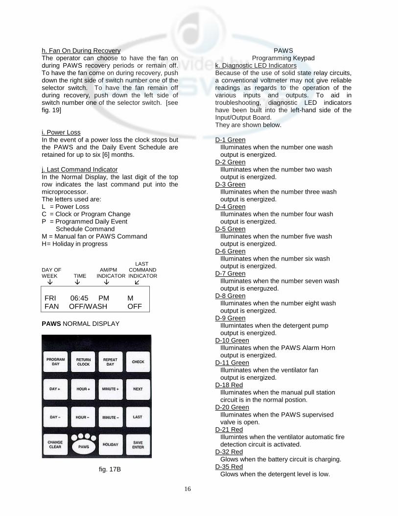
i. Power Loss In the event of a power loss the clock stops but the PAWS and the Daily Event Schedule are retained for up to six [6] months. j. Last Command Indicator In the Normal Display, the last digit of the top row indicates the last command put into the microprocessor. The letters used are: L = Power Loss C = Clock or Program Change P = Programmed Daily Event Schedule Command M = Manual fan or PAWS Command H = Holiday in progress LAST DAY OF AM/PM COMMAND WEEK TIME INDICATOR INDICATOR � � � � FRI 06:45 PM M FAN OFF/WASH OFF
PAWS NORMAL DISPLAY
fig. 17B
PAWS Programming Keypad
k. Diagnostic LED Indicators Because of the use of solid state relay circuits, a conventional voltmeter may not give reliable readings as regards to the operation of the various inputs and outputs. To aid in troubleshooting, diagnostic LED indicators have been built into the left-hand side of the Input/Output Board. They are shown below.
D-1 Green Illuminates when the number one wash output is energized. D-2 Green Illuminates when the number two wash output is energized. D-3 Green Illuminates when the number three wash output is energized. D-4 Green Illuminates when the number four wash output is energized. D-5 Green Illuminates when the number five wash output is energized. D-6 Green Illuminates when the number six wash output is energized. D-7 Green Illuminates when the number seven wash output is energuzed. D-8 Green Illuminates when the number eight wash output is energized. D-9 Green Illumintates when the detergent pump output is energized. D-10 Green Illuminates when the PAWS Alarm Horn output is energized. D-11 Green Illuminates when the ventilator fan output is energized. D-18 Red Illuminates when the manual pull station circuit is in the normal postion. D-20 Green Illuminates when the PAWS supervised valve is open. D-21 Red Illumintes when the ventilator automatic fire detection circuit is activated. D-32 Red Glows when the battery circuit is charging. D-35 Red Glows when the detergent level is low.

17
18
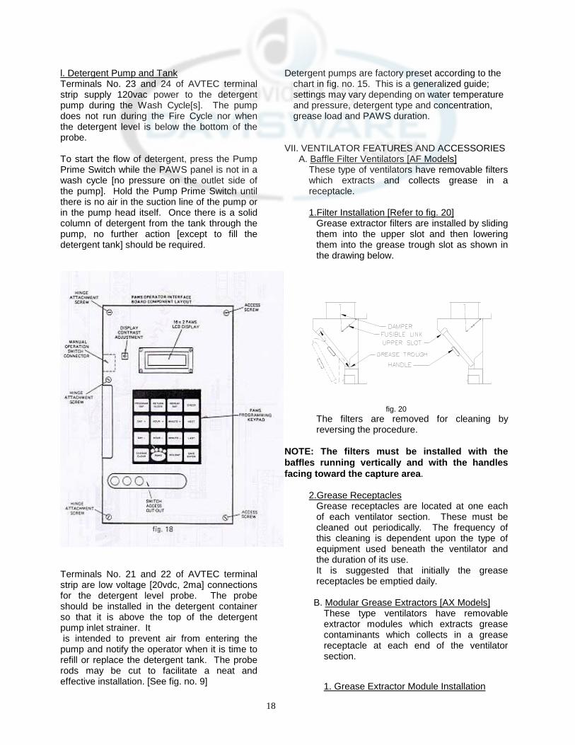
l. Detergent Pump and Tank Terminals No. 23 and 24 of AVTEC terminal strip supply 120vac power to the detergent pump during the Wash Cycle[s]. The pump does not run during the Fire Cycle nor when the detergent level is below the bottom of the probe.
To start the flow of detergent, press the Pump Prime Switch while the PAWS panel is not in a wash cycle [no pressure on the outlet side of the pump]. Hold the Pump Prime Switch until there is no air in the suction line of the pump or in the pump head itself. Once there is a solid column of detergent from the tank through the pump, no further action [except to fill the detergent tank] should be required.
Terminals No. 21 and 22 of AVTEC terminal strip are low voltage [20vdc, 2ma] connections for the detergent level probe. The probe should be installed in the detergent container so that it is above the top of the detergent pump inlet strainer. It is intended to prevent air from entering the pump and notify the operator when it is time to refill or replace the detergent tank. The probe rods may be cut to facilitate a neat and effective installation. [See fig. no. 9]
Detergent pumps are factory preset according to the chart in fig. no. 15. This is a generalized guide; settings may vary depending on water temperature and pressure, detergent type and concentration, grease load and PAWS duration.
VII. VENTILATOR FEATURES AND ACCESSORIES
A. Baffle Filter Ventilators [AF Models] These type of ventilators have removable filters which extracts and collects grease in a receptacle.
1.Filter Installation [Refer to fig. 20]
Grease extractor filters are installed by sliding them into the upper slot and then lowering them into the grease trough slot as shown in the drawing below.
fig. 20 The filters are removed for cleaning by reversing the procedure.
NOTE: The filters must be installed with the baffles running vertically and with the handles facing toward the capture area.
2.Grease Receptacles Grease receptacles are located at one each of each ventilator section. These must be cleaned out periodically. The frequency of this cleaning is dependent upon the type of equipment used beneath the ventilator and the duration of its use. It is suggested that initially the grease receptacles be emptied daily.
B. Modular Grease Extractors [AX Models] These type ventilators have removable extractor modules which extracts grease contaminants which collects in a grease receptacle at each end of the ventilator section.
1. Grease Extractor Module Installation
19
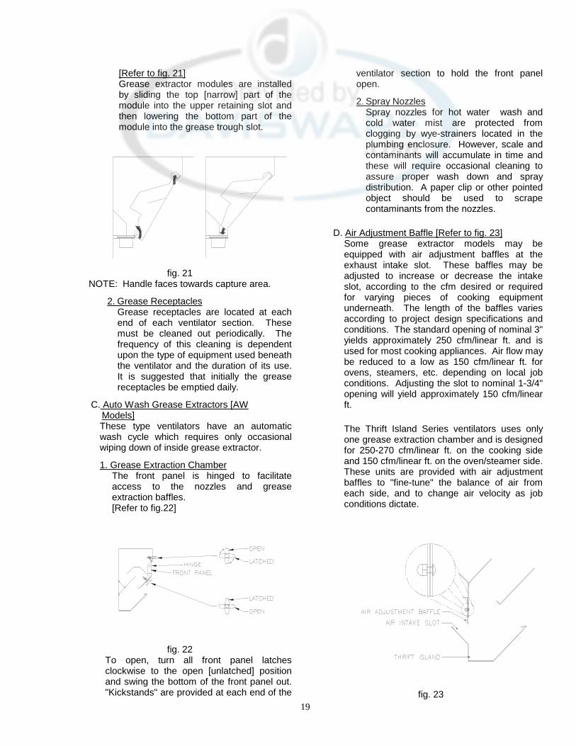
[Refer to fig. 21] Grease extractor modules are installed by sliding the top [narrow] part of the module into the upper retaining slot and then lowering the bottom part of the module into the grease trough slot.
fig. 21 NOTE: Handle faces towards capture area.
2. Grease Receptacles Grease receptacles are located at each end of each ventilator section. These must be cleaned out periodically. The frequency of this cleaning is dependent upon the type of equipment used beneath the ventilator and the duration of its use. It is suggested that initially the grease receptacles be emptied daily.
C. Auto Wash Grease Extractors [AW Models]
These type ventilators have an automatic wash cycle which requires only occasional wiping down of inside grease extractor.
1. Grease Extraction Chamber The front panel is hinged to facilitate access to the nozzles and grease extraction baffles. [Refer to fig.22]
fig. 22
To open, turn all front panel latches clockwise to the open [unlatched] position and swing the bottom of the front panel out. "Kickstands" are provided at each end of the
ventilator section to hold the front panel open.
2. Spray Nozzles Spray nozzles for hot water wash and cold water mist are protected from clogging by wye-strainers located in the plumbing enclosure. However, scale and contaminants will accumulate in time and these will require occasional cleaning to assure proper wash down and spray distribution. A paper clip or other pointed object should be used to scrape contaminants from the nozzles.
D. Air Adjustment Baffle [Refer to fig. 23] Some grease extractor models may be equipped with air adjustment baffles at the exhaust intake slot. These baffles may be adjusted to increase or decrease the intake slot, according to the cfm desired or required for varying pieces of cooking equipment underneath. The length of the baffles varies according to project design specifications and conditions. The standard opening of nominal 3" yields approximately 250 cfm/linear ft. and is used for most cooking appliances. Air flow may be reduced to a low as 150 cfm/linear ft. for ovens, steamers, etc. depending on local job conditions. Adjusting the slot to nominal 1-3/4" opening will yield approximately 150 cfm/linear ft.
The Thrift Island Series ventilators uses only one grease extraction chamber and is designed for 250-270 cfm/linear ft. on the cooking side and 150 cfm/linear ft. on the oven/steamer side. These units are provided with air adjustment baffles to "fine-tune" the balance of air from each side, and to change air velocity as job conditions dictate.
fig. 23

20
To adjust air intake slot, turn nuts to loosen, move air adjustment baffles up or down until the desired slot opening is obtained, and tighten nuts.
E. Fire Dampers 1. Fusible Link Type Some ducts are protected by fire dampers which are activated by a fusible link rated at 360°F exhaust and 286°F supply When this temperature is exceeded, the fusible link melts allowing the fire damper to fall closed. This linkage should be inspected and the fusible links replaced annually. Fusible links in the exhaust duct collar are readily accessible by removing the baffle filters [Models AF] or grease extractor modules [Models AX]. [Refer to fig. 20 and 24] An access plate is provided for access [supply] duct collar for all models.
fig. 24 Electro-Mechanical Type [Refer to fig. 24] Some ducts are protected by fire dampers which are activated by heat sensitive thermoswitches located near the duct inlet. These switches close electrically at temperatures above 300° F and activate a solenoid which releases the damper, and energizes a relay which activates the plenum auto wash/fire extinguishing spray and deactivates the fan. In the event of a loss of power, the damper assembly also contains a fusible link, set at 360°F.
The damper can be manually closed by pulling down on the red knob at the end of the damper reset arm and allowing it to swing away from the plenum.
If the damper has been activated by excessive temperature, it cannot be reset until the temperature has dropped below 300°
F. After the temperature has dropped below 300°F, the damper can be reset and opened by pushing the damper reset arm toward the plenum until it latches. If the fusible link has melted, it must be replaced before the damper can be reset. An access plate is provided.
When the damper is closed manually or if the fusible link melts and causes the damper to close, the fan and auto wash down are not affected.
When the damper closes due to activation of the thermoswitch, the fan[s] will shut OFF and the auto wash will actuate.
F. Air Make-Up [Supply] Plenums Ventilators may be supplied with four [4] different Air-Make-up plenums. Air is controlled by grill registers or a special E-Z Breeze perforated panel.
1. Grill Registers [Refer to fig. 25] Grill registers are located for external discharge or both internal and external discharge. Internal register have fixed louvers for proper "Short Cycle" of air. External registers have four-way louvers for adjusting direction of air flow to suit job requirements. Grill registers have opposing blade dampers located on the rear of the
register. The airflow may be adjusted by turning the damper adjustment screwhead located just behind the louvers as shown in fig. 25.
fig. 25 2. E-Z Breeze [Refer to fig. 26] The E-Z Breeze plenum is specially designed to slow the velocity of the supply air to minimize the energy costs incurred for tempering the air. The front perforated panel is removable for cleaning. Screws are provided to secure the panel in place after cleaning.
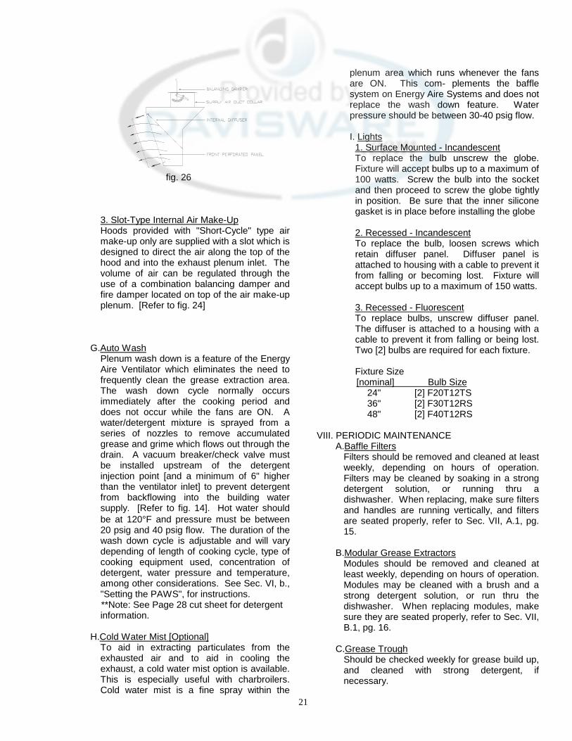
21
fig. 26 3. Slot-Type Internal Air Make-Up Hoods provided with "Short-Cycle" type air make-up only are supplied with a slot which is designed to direct the air along the top of the hood and into the exhaust plenum inlet. The volume of air can be regulated through the use of a combination balancing damper and fire damper located on top of the air make-up plenum. [Refer to fig. 24]
G.Auto Wash Plenum wash down is a feature of the Energy Aire Ventilator which eliminates the need to frequently clean the grease extraction area. The wash down cycle normally occurs immediately after the cooking period and does not occur while the fans are ON. A water/detergent mixture is sprayed from a series of nozzles to remove accumulated grease and grime which flows out through the drain. A vacuum breaker/check valve must be installed upstream of the detergent injection point [and a minimum of 6" higher than the ventilator inlet] to prevent detergent from backflowing into the building water supply. [Refer to fig. 14]. Hot water should be at 120°F and pressure must be between 20 psig and 40 psig flow. The duration of the wash down cycle is adjustable and will vary depending of length of cooking cycle, type of cooking equipment used, concentration of detergent, water pressure and temperature, among other considerations. See Sec. VI, b., "Setting the PAWS", for instructions. **Note: See Page 28 cut sheet for detergent information.
H.Cold Water Mist [Optional]
To aid in extracting particulates from the exhausted air and to aid in cooling the exhaust, a cold water mist option is available. This is especially useful with charbroilers. Cold water mist is a fine spray within the
plenum area which runs whenever the fans are ON. This com- plements the baffle system on Energy Aire Systems and does not replace the wash down feature. Water pressure should be between 30-40 psig flow. I. Lights
1. Surface Mounted - Incandescent To replace the bulb unscrew the globe. Fixture will accept bulbs up to a maximum of 100 watts. Screw the bulb into the socket and then proceed to screw the globe tightly in position. Be sure that the inner silicone gasket is in place before installing the globe
2. Recessed - Incandescent To replace the bulb, loosen screws which retain diffuser panel. Diffuser panel is attached to housing with a cable to prevent it from falling or becoming lost. Fixture will accept bulbs up to a maximum of 150 watts.
3. Recessed - Fluorescent To replace bulbs, unscrew diffuser panel. The diffuser is attached to a housing with a cable to prevent it from falling or being lost. Two [2] bulbs are required for each fixture.
Fixture Size [nominal] Bulb Size
24" [2] F20T12TS 36" [2] F30T12RS 48" [2] F40T12RS
VIII. PERIODIC MAINTENANCE
A.Baffle Filters Filters should be removed and cleaned at least weekly, depending on hours of operation. Filters may be cleaned by soaking in a strong detergent solution, or running thru a dishwasher. When replacing, make sure filters and handles are running vertically, and filters are seated properly, refer to Sec. VII, A.1, pg. 15.
B.Modular Grease Extractors
Modules should be removed and cleaned at least weekly, depending on hours of operation. Modules may be cleaned with a brush and a strong detergent solution, or run thru the dishwasher. When replacing modules, make sure they are seated properly, refer to Sec. VII, B.1, pg. 16.
C.Grease Trough
Should be checked weekly for grease build up, and cleaned with strong detergent, if necessary.
22
D. Grease Collection Receptacle
Should be emptied at least once a day, and cleaned daily with a strong detergent.
E. Hood Canopy
1. Inside hood canopy should be wiped down as needed. The area at the exhaust intake openings should be wiped down daily.
2. Inspect inside of extraction chamber at least monthly, to insure proper cleaning and that the trough is free of foreign matter.
F. Detergent System 1. Detergent tank should be checked at least weekly; and cleaned every six months. Always keep cover on tight to prevent spillage and evaporation.
2. A colloid type detergent, is recommended due to its non-caustic, non-toxic, biodegradable characteristics. It will not damage the rubber or synthetic parts of the pumping system. AVTEC recommends using EVAC Detergent. Available thru your local Service Agents or call Factory. See page 28 for more information.
3. All fittings should be checked for air tightness at least monthly.
4. Foot check valve should be cleaned every six months.
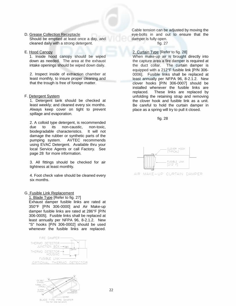
G. Fusible Link Replacement 1. Blade Type [Refer to fig. 27] Exhaust damper fusible links are rated at 350°F [P/N 306-0000] and Air Make-up damper fusible links are rated at 286°F [P/N 306-0005]. Fusible links shall be replaced at least annually per NFPA 96, 8-2.1.2. New "S" hooks [P/N 306-0002] should be used whenever the fusible links are replaced.
Cable tension can be adjusted by moving the eye-bolts in and out to ensure that the damper is fully open.
fig. 27 2. Curtain Type [Refer to fig. 28] When make-up air is brought directly into the capture area a fire damper is required at the duct collar. The curtain damper is equipped with a 212°F fusible link [P/N 306-0006]. Fusible links shall be replaced at least annually per NFPA 96, 8-2.1.2. New clover hooks [P/N 306-0007] should be installed whenever the fusible links are replaced. These links are replaced by unfolding the retaining strap and removing the clover hook and fusible link as a unit. Be careful to hold the curtain damper in place as a spring will try to pull it closed.
fig. 28
23
IX. PARTS LIST
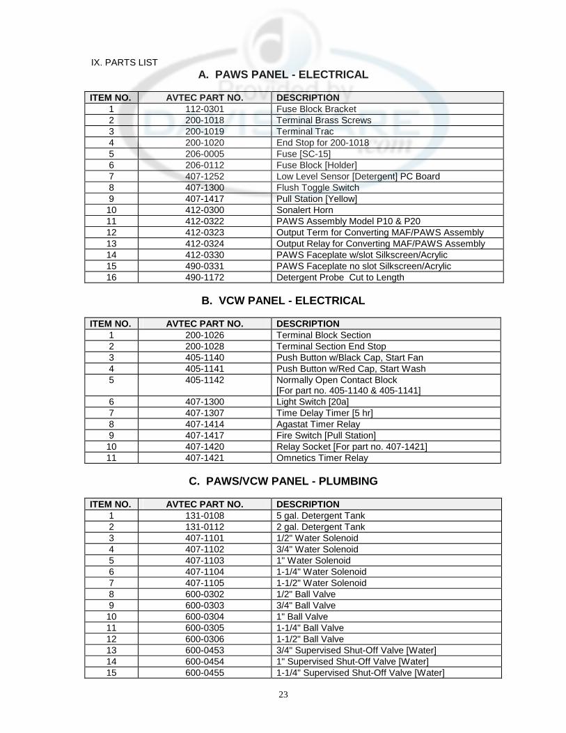
A. PAWS PANEL - ELECTRICAL
ITEM NO. AVTEC PART NO. DESCRIPTION 1 112-0301 Fuse Block Bracket 2 200-1018 Terminal Brass Screws 3 200-1019 Terminal Trac 4 200-1020 End Stop for 200-1018 5 206-0005 Fuse [SC-15] 6 206-0112 Fuse Block [Holder] 7 407-1252 Low Level Sensor [Detergent] PC Board 8 407-1300 Flush Toggle Switch 9 407-1417 Pull Station [Yellow] 10 412-0300 Sonalert Horn 11 412-0322 PAWS Assembly Model P10 & P20 12 412-0323 Output Term for Converting MAF/PAWS Assembly 13 412-0324 Output Relay for Converting MAF/PAWS Assembly 14 412-0330 PAWS Faceplate w/slot Silkscreen/Acrylic 15 490-0331 PAWS Faceplate no slot Silkscreen/Acrylic 16 490-1172 Detergent Probe Cut to Length
B. VCW PANEL - ELECTRICAL
ITEM NO. AVTEC PART NO. DESCRIPTION
1 200-1026 Terminal Block Section 2 200-1028 Terminal Section End Stop 3 405-1140 Push Button w/Black Cap, Start Fan 4 405-1141 Push Button w/Red Cap, Start Wash 5 405-1142 Normally Open Contact Block
[For part no. 405-1140 & 405-1141] 6 407-1300 Light Switch [20a] 7 407-1307 Time Delay Timer [5 hr] 8 407-1414 Agastat Timer Relay 9 407-1417 Fire Switch [Pull Station] 10 407-1420 Relay Socket [For part no. 407-1421] 11 407-1421 Omnetics Timer Relay
C. PAWS/VCW PANEL - PLUMBING
ITEM NO. AVTEC PART NO. DESCRIPTION
1 131-0108 5 gal. Detergent Tank 2 131-0112 2 gal. Detergent Tank 3 407-1101 1/2" Water Solenoid 4 407-1102 3/4" Water Solenoid 5 407-1103 1" Water Solenoid 6 407-1104 1-1/4" Water Solenoid 7 407-1105 1-1/2" Water Solenoid 8 600-0302 1/2" Ball Valve 9 600-0303 3/4" Ball Valve 10 600-0304 1" Ball Valve 11 600-0305 1-1/4" Ball Valve 12 600-0306 1-1/2" Ball Valve 13 600-0453 3/4" Supervised Shut-Off Valve [Water] 14 600-0454 1" Supervised Shut-Off Valve [Water] 15 600-0455 1-1/4" Supervised Shut-Off Valve [Water]

24
16 600-0456 1-1/2" Supervised Shut-Off Valve [Water] 17 600-1100 1/2" Check Valve, Br. 18 600-1101 3/4" Check Valve, Br. 19 600-1102 1" Check Valve, Br. 20 600-1103 3/8" Check Valve, Br. 21 600-1104 1/4" Check Valve, Br. 22 600-1105 1-1/4" Check Valve, Br. 23 600-1107 1-1/2" Check Valve, Br. 24 601-0051 1/2" Wye [Line] Strainer, B.I. 25 601-0052 3/4" Wye [Line] Strainer, B.I. 26 601-0053 1" Wye [Line] Strainer, B.I. 27 601-0054 1-1/4" Wye [Line] Strainer, B.I. 28 601-0055 1-1/2" Wye [Line] Strainer, B.I. 29 601-0103 1/2" Shock Arrestor 30 601-0153 1/2" Press/Temp. Gauge 31 601-0212 1/2" Vacuum Breaker, Br. 32 601-0213 3/4" Vacuum Breaker, Br. 33 601-0214 1" Vacuum Breaker, Br. 34 601-0215 1-1/4" Vacuum Breaker, Br. 35 601-0216 1-1/2" Vacuum Breaker, Br. 36 602-1403 3/4" Pressure Reducing Valve 37 602-1404 1" Pressure Reducing Valve 38 602-1405 1-1/4" Pressure Reducing Valve 39 602-1406 1-1/2" Pressure Reducing Valve, Br. 40 602-2000 Single Head Diaphragm Pump [Detergent] 41 602-2009 Foot Valve 42 602-2014 Check Anti-Syphon Valve
D. EVAC DETERGENT
ITEM NO. PART NO. DESCRIPTION 1 602-3001 EVAC 1 Gallon 2 602-3005 EVAC 5 Gallon 3 602-3030 EVAC 30 Gallon 4 602-3055 EVAC 55 Gallon
E. ELECTRO - MECHANICAL DAMPER
ITEM NO. AVTEC PART NO. DESCRIPTION
1 119-0406 1-1/2" S/S Spring 2 119-0600 Damper Spring [Right] 3 119-0601 Damper Spring [Left] 4 119-0603 Solenoid Return Spring 5 129-0202 Red Knob [Damper] 6 200-1026 Terminal Section 7 200-1028 Terminal Section End Stop 8 407-1283 Fire Relay [Damper] 9 407-1282 Damper Solenoid 10 407-1419 300°F, Normally Open Thermoswitch 11 411-0226 Electro-Mechanical Damper Instruction [Label] 12 205-0001 Convolution Boot 13 190-0404 AW Damper Linkage Assembly Complete 14 306-0000 350°F, Fusible Link 15 306-0003 Stainless Steel Cable 16 306-0004 Crimp Sleeve (For S.S. Cable)

25
17 144-0901 Small Linkage (Between 306-0000 and 144-0902) 18 144-0902 Large LInkage
F. FUSIBLE LINK DAMPER
ITEM NO. AVTEC PART NO. DESCRIPTION 1 120-7000 10" x 10" Balancing Damper 2 120-7001 16" x 10" Balancing Damper 3 120-7002 20" x 10" Balancing Damper 4 120-7003 30" x 10" Balancing Damper 5 120-7004 40" x 10" Balancing Damper 6 120-7100 10" x 10" Combo Balancing and Fire Damper 7 120-7101 16" x 10" Combo Balancing and Fire Damper 8 120-7102 20" x 10" Combo Balancing and Fire Damper 9 120-7103 30" x 10" Combo Balancing and Fire Damper 10 120-7104 40" x 10" Combo Balancing and Fire Damper 11 306-0000 Fusible Link 350°F 12 306-0001 Eye Bolt 3/16" x 2" - 10 - 24 13 306-0002 "S" Hook 14 306-0003 Stainless Steel Cable 15 306-0004 Crimp Sleeve [for S/S Cable] 16 306-0005 Fusible Link 286°F 17 306-0006 Fusible Link 212°F 18 306-0007 Clover Hook [Curtain Damper]
G. HOOD CANOPY
ITEM NO. AVTEC PART NO. DESCRIPTION 1 119-0211 Paddle Latch 2 119-0413 "Vice Action" Panel Latch 3 190-0380 16" x 16" S/S Filter 4 190-0383 20" x 25" S/S Filter 5 190-0398 20" x 20" S/S Filter 6 190-0400 20" x 20" Aluminum Filter 7 190-0401 16" x 16" Aluminum Filter 8 190-0405 Hanger Bracket [Ventilator] 9 190-0410 16" x 20" S/S Filter 10 190-0412 16" x 20" Aluminum Filter 11 190-0413 20" x 16" Aluminum Filter 12 190-0416 20" x 25" Aluminum Filter 13 190-0832 20" x 16" S/S Filter 14 412-0103 Incandescent Work Light Globe 15 412-0104 Incandescent Work Light Cage 16 412-0105 Incandescent Work Light Base 17 412-0115 3'-0" Fluorescent Work Light 18 412-0116 4'-0" Fluorescent Work Light 19 412-0117 2'-0" Fluorescent Work Light 20 412-0118 Recessed Incandescent Work Light 21 608-0410 Spray Nozzle, Br. No. 1/8 B-0.5-0.5W
[Cold Water Mist] 22 608-0412 Spray Nozzle, Br. No. 1/8 GG-2.8W ]Water 23 608-0413 Spray Nozzle, Br. No. 1/8 GGA-1.5W ]Wash 24 609-0050 2” Expandable Coupler
26
25 609-0051 2” PVC XMPT Adapter 26 609-0052 2” Male PVC Fitting
27
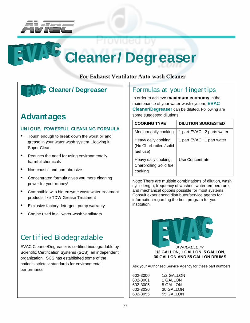
Cleaner/Degreaser
For Exhaust Ventilator Auto-wash Cleaner
Cleaner/Degreaser
Advantages UNIQUE, POWERFUL CLEANING FORMULA • Tough enough to break down the worst oil and
grease in your water wash system…leaving it Super Clean!
• Reduces the need for using environmentally harmful chemicals
• Non-caustic and non-abrasive
• Concentrated formula gives you more cleaning power for your money!
• Compatible with bio-enzyme wastewater treatment products like TDW Grease Treatment
• Exclusive factory detergent pump warranty
• Can be used in all water-wash ventilators.
Certified Biodegradable EVAC Cleaner/Degreaser is certified biodegradable by Scientific Certification Systems (SCS), an independent organization. SCS has established some of the nation’s strictest standards for environmental performance.
Formulas at your fingertips In order to achieve maximum economy in the maintenance of your water-wash system, EVAC Cleaner/Degreaser can be diluted. Following are some suggested dilutions:
COOKING TYPE DILUTION SUGGESTED
Medium daily cooking
Heavy daily cooking (No Charbroilers/solid fuel use)
Heavy daily cooking Charbroiling Solid fuel cooking
1 part EVAC : 2 parts water
1 part EVAC : 1 part water
Use Concentrate
Note: There are multiple combinations of dilution, wash cycle length, frequency of washes, water temperature, and mechanical options possible for most systems. Consult experienced distributor/service agents for information regarding the best program for your institution.
AVAILABLE IN
1/2 GALLON, 1 GALLON, 5 GALLON, 30 GALLON AND 55 GALLON DRUMS
Ask your Authorized Service Agency for these part numbers
602-3000 1/2 GALLON 602-3001 1 GALLON 602-3005 5 GALLON 602-3030 30 GALLON 602-3055 55 GALLON
28
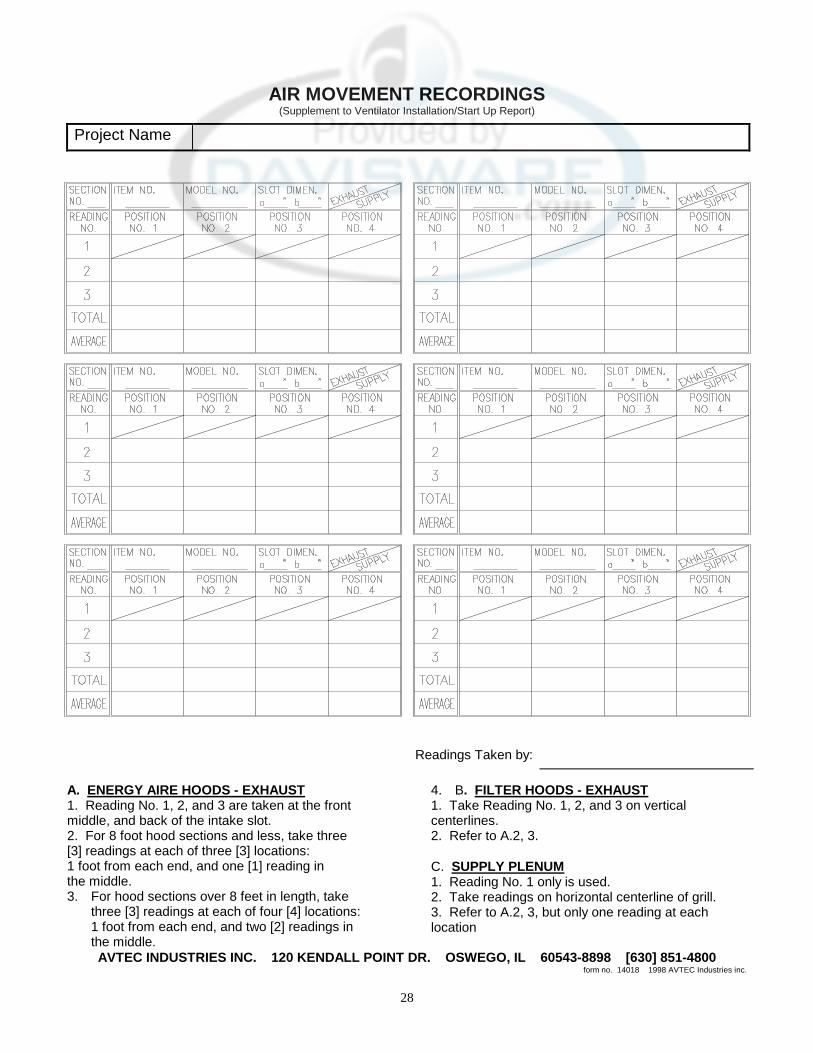
AIR MOVEMENT RECORDINGS
(Supplement to Ventilator Installation/Start Up Report)
Project Name
Readings Taken by:
A. ENERGY AIRE HOODS - EXHAUST 1. Reading No. 1, 2, and 3 are taken at the front middle, and back of the intake slot. 2. For 8 foot hood sections and less, take three [3] readings at each of three [3] locations: 1 foot from each end, and one [1] reading in the middle. 3. For hood sections over 8 feet in length, take
three [3] readings at each of four [4] locations: 1 foot from each end, and two [2] readings in the middle.
4. B. FILTER HOODS - EXHAUST 1. Take Reading No. 1, 2, and 3 on vertical centerlines. 2. Refer to A.2, 3. C. SUPPLY PLENUM 1. Reading No. 1 only is used. 2. Take readings on horizontal centerline of grill. 3. Refer to A.2, 3, but only one reading at each location
AVTEC INDUSTRIES INC. 120 KENDALL POINT DR. OSWEGO, IL 60543-8898 [630] 851-4800 form no. 14018 1998 AVTEC Industries inc.

29

30
CALCULATING AND RECORDING AIR MOVEMENT
1.) Cubic feet per minute or CFM'S is the total area multiplied by the average feet per
minute. A: CFM
AREA FPM B: CFM = AREA x AVG. FPM
FPM = CFM ÷ AREA AREA = CFM ÷ FPM
2.) AREA is the length of the opening multiplied by the width in inches. Divide the total
by 144 to get the total square feet (area).
EXHAUST A: Filter Hoods - Area = *Square Feet x Quantity of Filters
* 16 x 20 Filter = 1.75 Square Feet * 20 x 20 Filter = 2.25 Square Feet
B: Extractor Type Hoods - Area = **Square Feet x Quantity of Modules 16” Standard Module
**Low Volume Extractor w/3" Slot = .32352 Square Feet **High Volume Extractor w/4" Slot = .43136 Square Feet
9” Standard Module **Low Volume Extractor w/3" Slot = .1855 Square Feet **High Volume Extractor w/4" Slot = .2473 Square Feet
C: Water Wash Hood - Area = Length of Slot x Width of Slot in inches and
divided by 144 for square feet.
SUPPLY
A: Perforated Supply Air Panels - Square Feet of Panel x .4 = Area.
B: Register Type Supply Air Panels - Square Feet of Panel x .7 = Area.
31
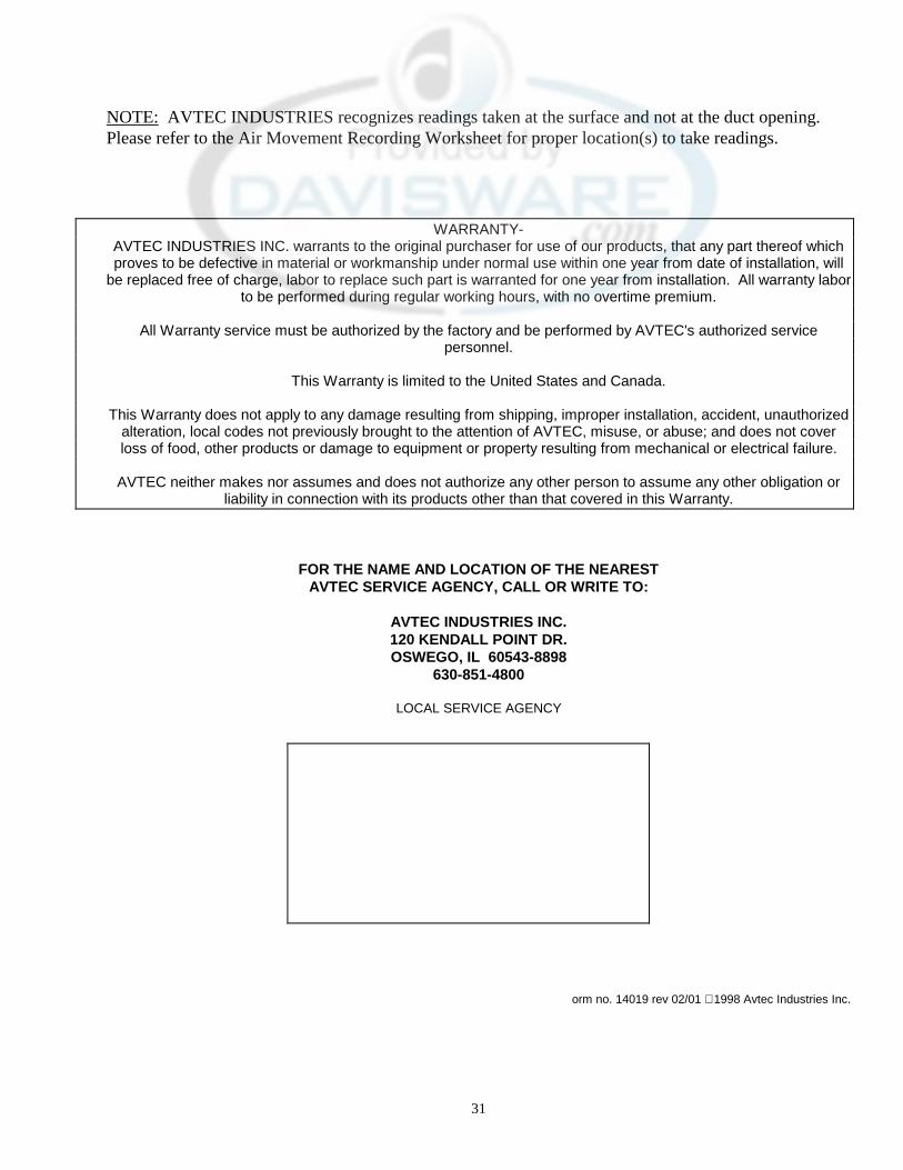
NOTE: AVTEC INDUSTRIES recognizes readings taken at the surface and not at the duct opening. Please refer to the Air Movement Recording Worksheet for proper location(s) to take readings.
WARRANTY- AVTEC INDUSTRIES INC. warrants to the original purchaser for use of our products, that any part thereof which proves to be defective in material or workmanship under normal use within one year from date of installation, will
be replaced free of charge, labor to replace such part is warranted for one year from installation. All warranty labor to be performed during regular working hours, with no overtime premium.
All Warranty service must be authorized by the factory and be performed by AVTEC's authorized service
personnel.
This Warranty is limited to the United States and Canada.
This Warranty does not apply to any damage resulting from shipping, improper installation, accident, unauthorized alteration, local codes not previously brought to the attention of AVTEC, misuse, or abuse; and does not cover loss of food, other products or damage to equipment or property resulting from mechanical or electrical failure.
AVTEC neither makes nor assumes and does not authorize any other person to assume any other obligation or
liability in connection with its products other than that covered in this Warranty.
FOR THE NAME AND LOCATION OF THE NEAREST AVTEC SERVICE AGENCY, CALL OR WRITE TO:
AVTEC INDUSTRIES INC. 120 KENDALL POINT DR. OSWEGO, IL 60543-8898
630-851-4800
LOCAL SERVICE AGENCY
orm no. 14019 rev 02/01 1998 Avtec Industries Inc.