Embed Size (px)
Citation preview
Installation Manual and Operating Guidelines
For Fiberglass Underground Storage Tanks
XERXES INSTALLATION MANuAL AND OPERATING GuIDELINES
TABLE OF CONTENTS
SECTIONS1. Introduction
1.1. Safety ........................................................................1
1.2. General ......................................................................1
1.3. Equipment .................................................................2
2. Handling and Storing Tanks
2.1. General ..........................................................................22.2. Unloading and Hoisting Tanks.....................................22.3. Storing Tanks ................................................................3
3. Preinstallation Inspection and Testing
3.1. General ..........................................................................33.2. Inspecting the Tank ......................................................43.3. Pretesting Procedures..................................................43.4. Preparing the Tank for Air Testing ...............................43.5. Pressurizing the Primary Tank .....................................53.6. Pressurizing the Interstitial Space
in a Dry Tank .................................................................53.7. Soaping the Tank ..........................................................53.8. Performing Visual Checks on a Tank
with a Wet Interstitial Space ........................................63.9. Releasing Pressure from the Tank...............................6
4. Preinstallation Testing For Specific Types of
Air-Testable Tanks
4.1. Air Testing a Single-Wall Tank ...................................6
4.2. Testing a Wet Double-Wall Tank ................................6
4.3. Testing a Dry-Monitor, Double-Wall Tank with the
Interstitial Space Under Vacuum ...................................7
4.4. Air Testing a Dry-Monitor, Double-Wall Tank.............7
4.5. Air Testing a Dry-Monitor, Double-Wall
Multicompartment Tank Not Under Vacuum .............7
5. Installing Tanks
5.1. General ..........................................................................85.2. Dry-Hole Installation .....................................................85.3. Wet-Hole Installation ..................................................10
6. Backfill Material
6.1. General ........................................................................10
6.2. Primary Backfill ...........................................................10
6.3. Secondary Backfill......................................................11
7. Excavation Requirements
7.1. General ....................................................................11
7.2. Excavation and Tank Location ................................11
7.3. Depth of Excavation ................................................12
7.4. Depth of Cover ........................................................12
7.5. Tank Spacing...........................................................13
8. Anchoring Systems
8.1. General ........................................................................14
8.2. Anchor Straps .............................................................14
8.3. Hardware and Anchor Points ....................................15
8.4. Deadmen .................................................................16
8.5. Xerxes Prefabricated Deadmen...............................16
8.6. Anchor Slabs ...........................................................17
8.7. Man-Out-of-Hole (MOH) Straps ..............................17
8.8. Alternate Wet-Hole Anchoring Method ...................17
9. Geotextile Fabric
9.1. General ......................................................................18
10. Bottom Sumps and Fittings
10.1. General ......................................................................18
11. Taking Diameter Measurements
11.1. General ......................................................................18
11.2. Diameter Measurement without a Standpipe ........19
11.3. Diameter Measurement with a Standpipe..............19
11.4. Calculation and Comparison...................................19
12. Ballasting Tanks (Adding Liquid)
12.1. General ......................................................................19
13. Postinstallation Testing
13.1. General ......................................................................20
13.2. Air Testing Tanks.......................................................20
13.3. Optional Hydrostatic Testing ...................................20
14. Piping and Venting
14.1. Internal Piping...........................................................20
14.2. External Piping..........................................................21
14.3. Venting Tanks............................................................21
14.4. Venting Interstitial Spaces .......................................22
15. Monitoring Tanks
15.1. General ......................................................................22
15.2. Single-Wall Tank .......................................................22
15.3. Double-Wall Tank .....................................................22
16. Installing Containment Sumps
16.1. General ......................................................................23
16.2. Final Containment Sump Installation......................24
17. Adding Tanks at Existing Locations
17.1. General ......................................................................24
17.2. Preferred Method .....................................................24
17.3. Alternate Method......................................................25
18. Operating Guidelines
18.1. General ......................................................................25
18.2. Temperature Limits for Stored Products
and Materials.........................................................25
18.3. Entering Tanks ..........................................................25
18.4. Filling Tanks (in General) ..........................................25
18.5. Filling UL-Labeled Tanks .........................................26
19. Limited Warranties
19.1. General ......................................................................26
20. Supplemental Materials
20.1. General ......................................................................26
21. Retention of Installation Manual
21.1. General ......................................................................26
APPENDICESA. Xerxes Tank Data Chart.....................................................27
B. Xerxes Primary Backfill Requirements ............................28
C. Xerxes Split Backfill Instructions .....................................29
XERXES TANK INSTALLATION CHECKLIST.........30
1. IntroduCtIon1.1. saFetY1.1.1. Before beginning the tank installation, read through the
entire Installation Manual and Operating Guidelines (subse-
quently referred to as Installation Manual). It is the responsibil-
ity of the owner, installer and operator to understand and
follow all requirements contained in this Installation Manual.
1.1.2. Work must be performed according to standard industry
practices that may apply to all aspects of tank installations
and operations.
1.1.3. Comply with all applicable federal, state and local regu-
lations and standards, such as:
• federal, state and local construction, health, safety and environmental codes
• National Fire Protection Association standards (for example, NFPA 30, 30A and 31)
• industry standard practices (for example, PEI RP100, API RP1615)
• EPA reference materials (for example, “Doing It Right”).
NOTE: A u.S. federal law (the Resource Conservation and
Recovery Act (RCRA), as amended (Pub. L. 98–616)) requires
owners of certain underground storage tanks to notify des-
ignated state or local agencies by May 8, 1986, of the exis-
tence of their tanks. Notifications for tanks brought into use
after May 8, 1986, must be made within 30 days. Consult
EPA’s latest regulations to determine if you are affected by
this law.
1.1.4. For additional information, contact relevant state,
county and city storage-tank authorities, including health, fire
or building departments, and environmental agencies.
1.1.5. The following definitions will serve as a guide when
reading the Installation Manual:
Indicates a potentially hazardous situation, which, if notavoided, could result in death or serious injury.
Indicates a potentially hazardous situation, which, if notavoided, may result in minor or moderate injury.
A Caution without the safety alert symbol indicates a poten-tially hazardous situation, which, if not avoided, may resultin property damage.
1.1.6. Keep this Installation Manual available at the installation
site to refer to safety procedures as needed.
Follow OSHA regulations for tank excavations. Collapse ofexcavation walls could result in death or serious injury.
1.1.7. Working in and around excavations is dangerous.The
Occupational Safety and Health Administration (OSHA) has
specific requirements that must be followed. Prior to begin-
ning work at the site, the installer must read and understand
OSHA’s Standard, Part 1926, Subpart P (Excavations), 650-
652. A copy of this standard is available free of charge at
www.osha.gov.
1.1.8. Ca reless activity or reckless operation of equipment can
cause death, serious injury or property damage.
1.1.9. Federal, state and local codes and regulations always
take precedence over a Xerxes requirement.
1.1.10. No instructions or procedures presented in this Installation
Manual should be interpreted so as to put at risk any person’s
health or safety, or to harm any property or the environment.
1.2. general1.2.1. It is important to follow the procedures and instructions
in this manual in order to safely and properly install a Xerxes
underground storage tank and accessories. Failure to follow
these instructions will void Xerxes’ obligations under the lim-
ited warranty, may result in tank failure or property damage,
and could cause serious personal injury or death.
1.2.1.1. The presence of a Xerxes representative does not relieve
the installer of responsibility for proper installation of the tank.
1.2.2. The Xerxes limited warranty applies only to a tank in-
stalled according to these instructions. Since Xerxes does not
control the parameters of any installation, Xerxes’ sole responsi-
bility in any installation is that presented in the limited warranty.
1.2.3. It is the responsibility of the owner and operator to al-
ways follow the operating guidelines set forth in Xerxes’ appli-
cable limited warranty and SECTION 18 of this Installation
Manual. It is the responsibility of the owner to retain this Instal-
lation Manual for future reference to operating guidelines.
1
XerXes InstallatIon Manual and operatIng guIdelInes
Read all instructions and operating guidelines before installation.
These instructions, which are based on successful experiences in a wide variety of situations, are issued as a guide for the
installation of Xerxes underground storage tanks. Compliance with the procedures and instructions contained in this Installa-
tion Manual are necessary for the proper installation of Xerxes tanks. Failure to comply will void the limited warranty for the
tank(s) and may cause tank failure.
To Installer: Before installation, read and understand the Installation Manual and Operating Guidelines (subsequently referred
to as Installation Manual). After installation, give the In stal la tion Manual with the completed Tank Installation Checklist (back of
manual) to the tank owner.
To Owner: After installation, retain the Installation Manual for future reference to operating guidelines and checklist.
1.2.3.1. A copy of the applicable Xerxes limited warranty is
found in the shipping documents that accompany each tank
when delivered.
1.2.3.2. A copy of the applicable Xerxes limited warranty is
also found in some of the applicable product brochures, at
www.xerxes.com and upon request from the Xerxes customer
service coordinator.
1.2.4. Use the Tank Installation Checklist (back of manual) for
all single-wall tanks (SW), double-wall tanks (DW), oil/water
separators (OWS) and multicompartment tanks (MC) as the in-
stallation proceeds.
1.2.5. Relevant information for each tank installed must be
recorded on the Tank Installation Checklist found at the back
of this manual. Consult the Xerxes customer service coordina-
tor if additional checklist forms are needed.
1.2.6. The tank owner should retain a copy of the completed
Tank Installation Checklist in order to facilitate any warranty
claim.
1.2.7. Xerxes recommends that the installing contractor also
keep a copy of the completed Tank Installation Checklist.
1.2.8. Xerxes must authorize—in writing and prior to tank in-
stallation—any variation to, or deviation from, the instructions
in the Installation Manual.
1.2.8.1. All correspondence regarding variations must be re-
tained for any warranty claim to be valid.
1.2.9. For any questions regarding the interpretation of these
instructions or for any other technical inquiries, contact techni-
cal support at Xerxes Minneapolis, MN.
1.2.10. All contact information applicable to installation is
found on the back cover of this manual.
1.3. eQuIpMent1.3.1. The following list is to be used as a guide for the equip-
ment recommended for installing Xerxes tanks:
1.3.1.1. excavation equipment capable of producing a level
bottom hole and placing backfill material at any point in the
excavation
1.3.1.2. suitable lifting equipment capable of lifting and placing
the tanks and associated tank anchors
1.3.1.3. spirit level or transit
1.3.1.4. 50-foot tape measure
1.3.1.5. tamping rod(s)
NOTE: A long wooden shovel handle is satisfactory.
1.3.1.6. pipe wrenches and appropriate pipe joint compound
1.3.1.7. a test manifold for each air-testable tank or compart-
ment—see FIGURE 3-2
1.3.1.8. source of pressurized air capable of 6 psig
1.3.1.9. soap and water solution (during freezing conditions, a
suitable solution such as windshield wiper fluid may be added
to the soap and water mixture)
1.3.1.10. soft cloth, brush or hand-held pneumatic sprayer
1.3.1.11. hand shovel
1.3.1.12. lifting sling(s)
1.3.1.13. soil compacting equipment (if necessary).
2. HandlIng and storIng tanKs2.1. general2.1.1. Although Xerxes tanks are rugged, the tank owner
and/or tank owner’s representative must take care so that the
tank is not dropped or damaged during loading, unloading,
handling and storage at the jobsite.
2.1.2. Move tanks by lifting and setting only. Do not move
tanks by rolling or dragging.
2.1.3. Always lift tanks by using the lifting lugs provided with
the tank. Distribute the lifting load evenly between the lifting
lugs. Use spreader bars and equal length slings as required.
NOTE: Larger tanks may be provided with guide lugs for at-
tachment of guide ropes during lifting and positioning oper-
ations. Do not use guide lugs for lifting.
Never roll, drag or drop the tank. This may result in damageto the tank.
2.2. unloadIng and HoIstIng tanKs2.2.1. Before the tank is unloaded or relocated on the job site (and
before preinstallation testing at the jobsite), tank owner and/or tank
owner’s representative must complete the following steps:
2.2.1.1. Visually inspect the entire exterior surface of the tank
to make sure that no shipping or handling damage has oc-
curred. Look particularly for visible damage, cracks or deep
scrapes.
2.2.1.2. Sign the shipping papers accepting the tank as deliv-
ered. Any damage observed must be noted in these papers.
2.2.1.3. Be sure that all equipment used to lift the tank is rated
to handle the load.
2.2.1.4. Select a smooth, solid, level area on which to place the
tank, and clear that area of all large rocks, trash and debris.
2.2.1.5. Make sure that all tools and other items that may dam-
age the tank during unloading are removed from the trailer bed.
2.2.2. When unloading the tank from the truck, tank owner
and/or tank owner’s representative must make sure that the
tank is secured in such a way that it does not roll off the truck.
Do not release straps securing the tank to the truck until lift-ing equipment (such as a crane) is secured to the tank’s lift-ing lug(s) and until anyone in a position to be injured by thetank's movement is in a safe location. Failure to do so couldresult in death, serious injury or property damage.
2.2.3. When hoisting the tank, follow these instructions—see
FIGURE 2-1 and FIGURE 2-2:
2.2.3.1. Choose suitable lifting sling(s) for the tank being installed.
2
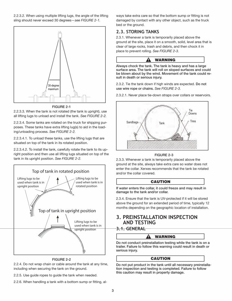
2.2.3.2. When using multiple lifting lugs, the angle of the lifting
sling should never exceed 30 degrees—see FIGURE 2-1.
FIGURE 2-12.2.3.3. When the tank is not rotated (the tank is upright), use
all lifting lugs to unload and install the tank. See FIGURE 2-2.
2.2.3.4. Some tanks are rotated on the truck for shipping pur-
poses. These tanks have extra lifting lug(s) to aid in the load-
ing/unloading process. See FIGURE 2-2.
2.2.3.4.1. To unload these tanks, use the lifting lugs that are
situated on top of the tank in its rotated position.
2.2.3.4.2. To install the tank, carefully rotate the tank to its up-
right position and then use all lifting lugs situated on top of the
tank in its upright position. See FIGURE 2-2.
FIGURE 2-22.2.4. Do not wrap chain or cable around the tank at any time,
including when securing the tank on the ground.
2.2.5. Use guide ropes to guide the tank when needed.
2.2.6. When handling a tank with a bottom sump or fitting, al-
ways take extra care so that the bottom sump or fitting is not
damaged by contact with any other object, such as the truck
bed or the ground.
2.3. storIng tanKs2.3.1. Whenever a tank is temporarily placed above the
ground at the site, place it on a smooth, solid, level area that is
clear of large rocks, trash and debris, and then chock it in
place to prevent rolling. See FIGURE 2-3.
Always chock the tank. The tank is heavy and has a largesurface area. The tank will roll on sloped surfaces and couldbe blown about by the wind. Movement of the tank could re-sult in death or serious injury.
2.3.2. Tie the tank down if high winds are expected. Do not
use wire rope or chains. See FIGURE 2-3.
2.3.2.1. Never place tie-down straps over collars or reservoirs.
FIGURE 2-32.3.3. Whenever a tank is temporarily placed above the
ground at the site, always take extra care so water does not
enter the collar. Xerxes recommends that the tank be rotated
and/or the collar covered.
If water enters the collar, it could freeze and may result indamage to the tank and/or collar.
2.3.4. Ensure that the tank is UV-protected if it will be stored
above the ground for an extended period of time, typically 12
months depending on the geographic location of installation.
3. preInstallatIon InspeCtIon and testIng
3.1. general
Do not conduct preinstallation testing while the tank is on atrailer. Failure to follow this warning could result in death orserious injury.
Do not put product in the tank until all necessary preinstalla-tion inspection and testing is completed. Failure to followthis caution may result in property damage.
Lifting lugs to be used when tank is inupright position
Top of tank in upright position
Top of tank in rotated position
Lifting lugs to be used when tank is inupright position
Lifting lugs to be used when tank is inrotated position
30-degreemaximum
TieDowns
TiresTankSandbags
3
3.1.1. The applicable inspection and testing procedures set
forth in SECTIONS 3 and 4 must be performed to validate the
limited warranty.
3.1.2. All tanks are tested and inspected at the factory prior to
shipment. However, in order to verify the absence of any dam-
age resulting from shipping or handling, prior to installation all
tanks must also be inspected at the site. Some tanks must
also be tested at the site prior to installation according to the
applicable procedures.
Always secure the tank before moving, rotating or lifting it.This is commonly done by connecting a crane or backhoe tothe lifting lugs. Failure to follow this warning could result indeath or serious injury.
While moving or lifting the tank, do not position any partof your body underneath the tank. Failure to follow thiswarning could result in death or serious injury.
Do not lift or hoist a tank under pressure. Failure to followthis warning could result in death or serious injury.
3.1.3. Not all tanks are air-testable in the field. If a tank needs
to be hydrostatica lly tested, see SECTION 13.3.
3.1.4. If the tank is a water/wastewater tank equipped for op-
tional preinstallation testing, after inspecting the tank (see
SECTION 3.2.), follow procedures in the Xerxes supplement,
Preinstallation Testing Instructions for Water/Wastewater Tanks
Factory-Equipped for Pressure Testing. See SECTION 20 for
information on how to obtain this supplement.
3.1.5. If damage of any kind is detected, contact the plant
from which the tank was shipped before installing the tank.
NOTE: Do not attempt unauthorized repairs.
3.2. InspeCtIng tHe tanK3.2.1. Thoroughly inspect the entire outside surface of the tank
for signs of shipping or handling damage. Rotate or lift the
tank to inspect the bottom of the tank.
3.2.2. If damage of any kind is detected, contact the plant
from which the tank was shipped before installing the tank.
NOTE: Do not attempt unauthorized repairs.
3.3. pretestIng proCedures
Do not install any piping or fittings other than test fittingsuntil all preinstallation testing has been completed. Failureto follow this caution may result in property damage.
Never pressurize a wet interstitial space. Doing so may re-sult in damage to the primary tank and/or tank failure.
3.3.1. All UL-labeled tanks, chemical tanks and potable water
tanks must be air tested after backfill is brought close to the
top of the tank.
3.3.2. If the tank being installed is not an air-testable tank, pro-
ceed to SECTION 5.
3.3.3. See SECTIONS 3.4. through 3.9. for specific instruc-
tions for preinstallation testing procedures.
3.3.4. See SECTION 4 for preinstallation testing instructionsfor specific types of air-testable tanks.
3.3.5. Someone must be with the tank at all times during air
testing.
3.3.6. Prior to the pressure test, remove all plugs, apply
sealant, and replace and tighten plugs.
When the tank is under pressure, the manways, accessopenings and/or fittings may dislodge, or the tank couldrupture, and this could result in death or serious injury. Be-fore beginning the air test, notify all people on the test siteto remain in a safe location. NEVER LEAVE A TANK uNDERPRESSuRE uNATTENDED. Stand clear of manways, fittingsand tank ends during the test.
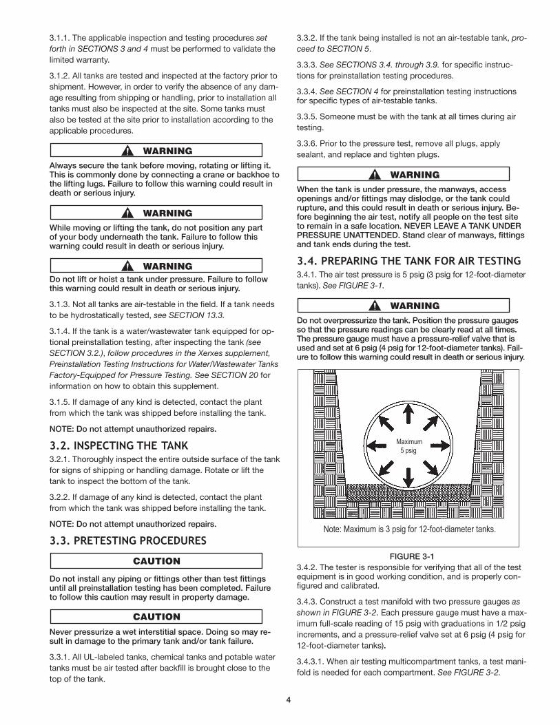
3.4. preparIng tHe tanK For aIr testIng3.4.1. The air test pressure is 5 psig (3 psig for 12-foot-diameter
tanks). See FIGURE 3-1.
Do not overpressurize the tank. Position the pressure gaugesso that the pressure readings can be clearly read at all times.The pressure gauge must have a pressure-relief valve that isused and set at 6 psig (4 psig for 12-foot-diameter tanks). Fail-ure to follow this warning could result in death or serious injury.
FIGuRE 3-1
3.4.2. The tester is responsible for verifying that all of the testequipment is in good working condition, and is properly con-figured and calibrated.
3.4.3. Construct a test manifold with two pressure gauges as
shown in FIGURE 3-2. Each pressure gauge must have a max-
imum full-scale reading of 15 psig with graduations in 1/2 psig
increments, and a pressure-relief valve set at 6 psig (4 psig for
12-foot-diameter tanks).
3.4.3.1. When air testing multicompartment tanks, a test mani-
fold is needed for each compartment. See FIGURE 3-2.
Maximum5 psig
Note: Maximum is 3 psig for 12-foot-diameter tanks.
4
FIGuRE 3-2
NOTE: All compartments on a double-wall tank may be man-
ifolded together and tested simultaneously, or each com-
partment may be tested separately.
3.4.3.2. A test manifold is needed for testing the dry interstitial
space of an air-testable, double-wall tank. See FIGURE 3-2.
NOTE: A test manifold is not required for a tank with an in-
terstice filled with monitoring fluid.
3.4.4. During air tests, ambient air temperature can affect
pressure-gauge readings.
Allow for pressure variations when tanks are subject toabrupt temperature changes. Failure to follow this cautionmay result in minor or moderate injury.
3.4.5. When testing tanks with wet monitoring, remove the
reservoir-fitting plug.
3.4.6. If the tank has threaded fittings, it is the installer’s re-
sponsibility to select a thread sealant that is compatible with
the product being stored. Some sealants cannot be used with
some stored products.
3.4.7. Install permanent plugs in all openings where piping will
not be installed.
3.4.8. Make sure all manway bolts are tightened, and fitting
plugs are properly doped and sealed.
3.4.8.1. The tank may be air tested with the factory-supplied
temporary plugs. Redope and tighten temporary plugs if
needed.
3.4.9. Keep one service fitting open in each compartment for
the test manifold.
3.4.10. Tanks equipped with flanged nozzles may require con-
tractor-supplied blind flanges for preinstallation air testing.
3.5. pressurIZIng tHe prIMarY tanK3.5.1. Install the test manifold in the open service fitting and con-
nect the pressure source to the test manifold. See FIGURE 3-3.
3.5.2. If the interstitial space is dry, install the test manifold
and close the valve before pressurizing the primary tank.
3.5.3. Open the air-supply valve and pressurize the primary tank
to 5 psig (3 psig for 12-foot-diameter tanks). Allow a few min-
utes for the air temperature in the tank to stabilize, then allow
the pressure to stabilize by adding or removing air as necessary.
3.5.4. Hold and monitor the pressure for a minimum of 1 hour.
3.5.4.1. If the test manifold shows a pressure build-up in the
interstitial space of a dry-monitor, double-wall tank, contact
the plant from which the tank was shipped.
NOTE: Do not attempt unauthorized repairs.
3.6. pressurIZIng tHe InterstItIal spaCeIn a drY tanK
Never lift or hoist a tank under pressure. Failure to followthis warning could result in death or serious injury.
NOTE: Do not attempt unauthorized repairs.
3.6.1. Tanks with a dry interstitial space not shipped under vac-
uum come with a quick-disconnect assembly. See FIGURE 3-3.
FIGuRE 3-3
3.6.2. If the tank is not configured as shown in FIGURE 3-3
prior to preinstallation testing, contact the plant from which
the tank was shipped.
3.6.3. The quick-disconnect assembly must not be connected
to the service fitting when air testing the primary tank. Keep
the nylon tie in place.
3.6.4. Maintain the pressure in the primary tank.
Do not connect the air supply directly to the interstitial-space monitoring access fitting. Pressurizing the secondarytank (in ter sti tial space) by itself may damage the primarytank or cause tank failure.
3.6.5. Free the hose from the service fitting by cutting the
nylon tie.
3.6.6. Insert the hose into the quick-disconnect fitting. This will
allow air to transfer from the primary tank to the interstitial space.
3.6.7. Reconnect the air-supply line. Allow the pressure to sta-
bilize at 5 psig (3 psig for 12-foot-diameter tanks) by adding or
removing air as necessary.
3.6.8. Close the air-supply valve on the test manifold and dis-
connect the air-supply line.
3.7. soapIng tHe tanK3.7.1. After pressurizing the tank, soap the tank to check the
tank’s integrity.
3.7.1.1. Soap either the fittings, manways and covers or the
entire exterior of the tank, depending on what part of the test-
ing process the tester is at and what kind of tank is being air
tested. See SECTION 4 instructions for specific types of tanks.
3.7.1.2. Watch for active air bubbles. There should not be any.
Nylon tie
Quick-disconnectassembly
Monitoring access fitting
air-pressure gauge
air-supply valve
pressure-reliefdevice
air-pressure gauge
to air supply on interstitialtest manifold
5
NOTE: During freezing conditions, a suitable solution such
as windshield washer fluid may be added to the soap and
water mixture.
3.7.2. When doing a soap test, rotate the tank to check the
bottom. Do not rotate a tank filled with monitoring fluid.
3.7.2.1. Before rotating the tank, place protective material on
the area on which the tank will be rotated. Make sure the area
is flat and free of large or sharp objects, such as rocks, which
may damage the tank.
3.7.2.2. Rotate the tank slowly and carefully to avoid develop-
ing too much momentum. Momentum can grow because
manways and fittings on top of the tank make it top heavy.
Make sure the tank’s fittings and manways never touch the
ground. Do not rotate the tank more than 120 degrees from
the initial starting point.
3.7.3. If damage is detected, contact the plant from which the
tank was shipped.
NOTE: Do not attempt unauthorized repairs.
3.8. perForMIng VIsual CHeCKs on a tanKWItH a Wet InterstItIal spaCe
Never pressurize a wet interstitial space. Doing so maydamage the primary tank or cause tank failure.
Never rotate a tank filled with monitoring fluid. Doing somay result in damage to the tank and/or tank failure.
3.8.1. Check that the tank has monitoring fluid in the reservoir.
Measure the level of the monitoring fluid in the reservoir.
NOTE: If the reservoir is less than a third full, contact the
plant from which the tank was shipped. See the back cover
of the Installation Manual for contact numbers.
3.8.2. Visually check the interior of the tank for monitoring
fluid. There should not be any.
3.8.2.1. When checking a multicompartment tank, inspect the
interior of each compartment for monitoring fluid.
3.8.3. Visually check the exterior of the tank for monitoring
fluid. (The monitoring fluid is dyed blue to distinguish between
moisture and monitoring fluid.) If monitoring fluid is found, wipe
the tank dry and verify that the monitoring fluid does not reap-
pear. Lift the tank to check the bottom. Do not roll the tank.
3.8.3.1. When checking a multicompartment tank, inspect the
exterior of each compartment for monitoring fluid.
3.9. releasIng pressure FroM tHe tanK3.9.1. If there is an interstitial space to pressurize, open the
valve of the test manifold and carefully release the air pressure
in the interstitial space first.
3.9.2. If the tank is a multicompartment tank, carefully release
the air pressure in the end compartments first.
3.9.3. Then carefully release the air pressure from the base tank.
Never allow the pressure in the interstitial space to begreater than the pressure in a primary tank. Failure to followthis caution may result in damage to a primary tank and/ortank failure.
Never remove the service-fitting plugs when there is pres-sure in the tank. Failure to follow this warning could result indeath or serious injury.
3.9.4. Remove the test manifolds and replace the protective
covers in the service fittings.
4. PREINSTALLATION TESTING FOR
SPECIFIC TYPES OF AIR-TESTABLE TANKS
NOTE: When air testing a tank, follow the procedures out-
lined here for the specific type of tank being installed. For
more specific details on these procedures, see the SECTION
3 SECTIONS and SuBSECTIONS to which you are referred.
4.1. aIr testIng a sIngle-Wall tanK4.1.1. Prepare the tank for air testing. See SECTION 3.4.
4.1.2. Pressurize the tank. See SECTION 3.5.
4.1.3. Soap the entire exterior of the tank. See SECTION 3.7.
4.1.4. Hold and monitor the pressure for a minimum of 1 hour.
4.1.5. Carefully release the air pressure from the tank. See
SECTION 3.9.
4.1.6. Remove the test manifold and replace the protective
covers in the service fittings.
4.2. testIng a Wet douBle-Wall tanK
Never pressurize a wet interstitial space. Doing so may re-sult in damage to the primary tank and/or tank failure.
4.2.1. Check the level of the monitoring fluid in the reservoir.
See SECTION 3.8. for instructions.
4.2.2. Visually check the interior and the exterior of each com-
partment for the presence of monitoring fluid. See SECTION
3.8. for instructions.
4.2.3. If the monitoring fluid is not at the proper level, and/or moni-
toring fluid is found on either the interior or the exterior of any
compartment, contact the plant from which the tank was shipped.
4.2.4. If there is no monitoring fluid on either the interior or the
exterior of any compartment, proceed to backfill the tank to
the top of the tank.
4.2.5. After the tank is backfilled to the top of the tank, it must
be air tested. See SECTION 13 for instructions.
4.3. testIng a drY-MonItor, douBle-Wall tanKWItH tHe InterstItIal spaCe under VaCuuM4.3.1. A dry-monitor, double-wall tank may be shipped from
the factory with the interstitial space under vacuum. This op-
tion allows for monitoring the tank during shipping and han-
dling, and may expedite tank installation by shortening
6
preinstallation testing procedures. The date that the vacuum
was applied is on a label by the monitor or on the shipping
documentation delivered with the tank.
4.3.1.1. This date may be used as a reference under this pro-
cedure to evaluate the tank’s integrity prior to installation, and
to validate Xerxes’ obligations under the limited warranty.
4.3.1.2. Xerxes tanks shipped under vacuum must be under
vacuum for a minimum of 7 days. If this requirement is not met,
an air/soap test is required. See SECTION 4 for instructions.
4.3.1.3. The tank shipped under vacuum should be installed
and backfilled with the vacuum intact if both of the following
two conditions are met:
4.3.1.3.1. installation of the tank is to begin 7 days or more
after the factory application of vacuum (as indicated on the
shipping documents and/or tank labels)
4.3.1.3.2. the vacuum gauge shipped with the tank reads 12
inches of mercury or more.
NOTE: The vacuum-monitoring method is less sensitive and
less reliable than the soap test described in SECTION 3.7.
Under certain field conditions (such as major changes in
temperature, barometric pressure and/or altitude) and/or
with certain equipment failure (such as freezing or sticking
of gauge mechanism), the vacuum-monitoring method may
not be an accurate enough test. When in doubt, or when
such conditions occur, Xerxes recommends SECTION 4.4. or
4.5. (whichever is applicable) as the preferred preinstallation
test procedure.
4.3.1.4. After the tank is backfilled to the top of the tank, the
tank must be air tested. See SECTION 13 for instructions.
4.3.1.5. If either or both of the conditions stated in POINTS
4.3.1.3.1. and 4.3.1.3.2. are not met, follow the procedures of
SECTION 4.4. or 4.5. (whichever is applicable) for the prein-
stallation test.
4.3.1.5.1. If the gauge reads less than 12 inches of mercury,
perform a visual inspection of the exterior of the tank and the
vacuum gauge fittings to evaluate the tank’s integrity, and
contact the plant from which the tank was shipped.
NOTE: Do not attempt unauthorized repairs.
4.3.1.6. Record the vacuum gauge reading at the time of in-
stallation on the Tank Installation Checklist.
4.4. AIR TESTING A DRY-MONITOR, DOUBLE-WALL TANK
4.4.1. Prepare the tank for air testing. See SECTION 3.4.
4.4.2. Pressurize the primary tank. See SECTION 3.5.
4.4.3. Soap all service fittings and manways. See SECTION 3.7.
4.4.4. Hold and monitor the pressure in the primary tank for a
minimum of 1 hour.
4.4.5. Use the quick disconnect assembly to pressurize the in-
terstitial space. See SECTION 3.6.
4.4.6. Soap the entire exterior of the tank. See SECTION 3.7.
4.4.7. Hold and monitor the pressure in the interstitial space
for a minimum of 1 hour.
4.4.8. Carefully release the air pressure from the tank. See
SECTION 3.9.
4.4.9. Remove the test manifold and replace the protective
covers in the service fittings.
4.5. AIR TESTING A DRY-MONITOR, DOUBLE-WALLMULTICOMPARTMENT TANK NOT UNDER VACUUM
Do not connect air supply directly to the interstitial-spacemonitoring access fitting. Pressurizing the in ter sti tial spaceby itself may result in damage to the primary tank and/ortank failure.
4.5.1. Prepare the tank for air testing. See SECTION 3.4.
4.5.1.1. Install a test manifold in each compartment, that is, in
the base tank and each end compartment. See FIGURE 4-1.
FIGURE 4-1
4.5.2. Pressurize the primary tank. See SECTION 3.5 and
FIGURE 4-2.
FIGURE 4-2
4.5.3. Pressurize the end compartment(s). See SECTION 3.5.
and FIGURE 4-3.
FIGURE 4-3
4.5.4. Soap all service fittings, manways and covers. See
SECTION 3.7.
4.5.5. Hold and monitor the pressure for a minimum of 1 hour.
4.5.6. Use the quick-disconnect assembly to pressurize the in-
terstitial space. See SECTION 3.6. and FIGURE 4-4.
Typical manway with fittings
Lifting lug Typical
service fitting
Monitoring accessfitting (dry interstitial space)
EndCompartment
EndCompartment Base tank
Seam for end compartmentSeam for base tank
Seam for end compartment
FlatRib
Optional reservoir (wet interstitial space)
Pressure-relief valve for shipping
Air Test of Base Tank
Air Test of End Compartment(s)
7
FIGuRE 4-4
4.5.7. Soap the entire exterior of the tank. See SECTION 3.7.
4.5.8. Hold and monitor the pressure for a minimum of 1 hour.
4.5.9. Carefully release the air pressure from the tank. See
SECTION 3.9.
4.5.10. Remove the test manifolds and replace the protective
covers in the service fittings.
5. InstallIng tanKs
If product is used as ballast, exercise special care in han-dling. Safeguard against sparks, fire or product spills. Im-proper handling of product could cause a fire or ex plo sionand could result in death or serious injury.
Do not use air pressure to test tanks that contain or havecontained flammable or combustible liquids or vapors. Thefuel and air mixture could explode and could result in deathor serious injury. Tanks should be air tested before ballast-ing. See SECTION 12.
Adequately ballast the tank (add liquid) in a wet hole or in adry hole that may become wet (for example, from site runoff)until the installation is totally completed. Failure to do thismay result in damage to the tank and/or surrounding property.
5.1. general5.1.1. Take safety precautions throughout the entire installation
process. See SECTIONS 1.1. and 7.1.
5.1.2. Use only approved backfill material. See SECTION 6.
5.1.3. Do not mix approved material together with sand or in
situ soil.
5.1.4. Do not use in situ soil as primary backfill material.
5.1.5. Typically, all excavated in situ soil must be replaced with
primary backfill material.
5.2. drY-Hole InstallatIon5.2.1. Before beginning tank installation, take a tank diameter
measurement. See SECTION 11 for instructions.
5.2.2. Record this measurement as Measurement #1 on the
Tank Installation Checklist.
5.2.3. Locate the excavation site according to instructions in
SECTIONS 7.1. and 7.2.
5.2.4. Prepare the excavation according to instructions in
SECTION 7.
5.2.4.1. When preparing the excavation, allow for an anchoring
system (if used) and geotextile fabric (if used). See SECTIONS
7.2., 7.3. and 7.4.
5.2.4.2. When preparing the excavation, allow for the appropri-
ate depth of cover as specified in SECTION 7.4.
5.2.4.3. If two or more tanks are to be installed in the same ex-
cavation hole, follow instructions in SECTION 7.5.
5.2.4.4. If the tank has a bottom sump or fitting, prepare the
excavation hole according to instructions in SECTION 10.
5.2.5. Remove all loose material from the excavation.
5.2.6. Where necessary, level the bottom of the excavation
using primary backfill material, filling in any low areas. See
SECTION 6 for backfill requirements.
5.2.7. If an anchor slab is needed, install it now. See POINT
7.5.3.3. and SECTION 8.6.
5.2.8. If geotextile fabric is to be used, place it in the excava-
tion hole at this time. See SECTION 9.
5.2.8.1. Geotextile must be placed to separate the primary
backfill material from all other in situ soil and/or secondary
backfill material.
5.2.9. If deadmen are used, see SECTION 8 for information on
deadmen placement and place them now.
5.2.9.1. If deadmen are used and they are to be placed so that
they are in the bedding or below the bottom of the tank, place
the deadmen before preparing the backfill bedding.
5.2.10. Prepare a 12-inch-thick smooth, level bed of approved
primary backfill material on the bottom of the excavation. See
SECTION 6 for backfill requirements.
If anchor straps are used, bedding must be carefully leveled.Failure to follow this caution may result in straps being tooshort or too long, and may result in property damage.
5.2.10.1. If the excavation has soft soil conditions or if there
might be difficulties controlling water accumulation, it is ac-
ceptable to increase the bedding thickness to 18 inches and
set the tank anchors 6 inches off the bottom of the excavation
(9 inches for 10-foot-diameter tank deadmen).
5.2.11. See SECTION 2 regarding the use of lifting lugs to
hoist the tank when unloading and installing it.
5.2.12. Place the tank or tanks onto the bed.
5.2.12.1. If deadmen are in place, center the tanks between them.
Do not set tanks directly onto a concrete slab, timbers,cradles or in situ soil. Failure to follow this caution mayresult in damage to the tank.
5.2.12.2. Align the tanks with anchors for proper placement of
anchor straps.
5.2.12.3. As the tank is being placed, slope the tank according
to site specifications.
NOTE: Xerxes does not require that a tank be sloped. The
slope is determined by the tank owner’s spec i fi ca tions.
Air-test Monitoring of Secondary Tank (dry interstitial space)
8
5.2.12.3.1. Sloping of tanks may affect accuracy of cal i bra tion
charts.
5.2.12.3.2. If a double-wall tank is sloped, the monitor should
be at the low end.
5.2.13. Use the tops of the ribs to establish longitudinal level.
Establish lateral level by placing the level across the top of a
fitting or a manway.
5.2.14. If anchor straps are to be used, install them at this
time. See SECTION 8.2.
5.2.14.1. The locations for anchor straps are marked on tank
ribs by the arrowhead symbol (on the tank itself on 4-foot-
diameter tanks).
5.2.14.2. All marked anchor strap locations must have straps.
Do not place straps between ribs. Failure to properly placestraps may result in damage to the tank.
5.2.14.3. Place a strap on each marked location and install an-
choring hardware. See SECTION 8.
5.2.14.4. Tighten each anchor strap until it is snug over the rib
(over the tank itself in 4-foot-diameter tanks) but causes no
deflection of the tank. Straps must be uniformly tight.
5.2.14.5. The elevation of deadmen is critical. If a strap ap-
pears too short or there is not sufficient adjustment in the turn-
buckle to make the strap snug, the tank and/or tank anchors
must be repositioned by adding or removing backfill material
until the straps are properly installed.
NOTE: Make sure that the minimum bedding thickness of
12 inches has been maintained.
5.2.14.6. After the straps have been installed and tightened,
take a tank diameter measurement to check tank deflection,
and record it as Measurement #2 on the Tank Installation
Checklist.
Overdeflection of the tank may result in damage to the tank.
5.2.15. On water/wastewater tanks with bottom fittings, piping
needs to be installed at this time.
5.2.16. Place approximately 12 inches of primary backfill
around the bottom of the tanks between the ribs (if present)
and under the end domes.
5.2.16.1. Use a nonmetal tamping rod long enough to reach
beneath the tank to push material under the tank body and
domes until solid resistance is felt, all voids are filled and the
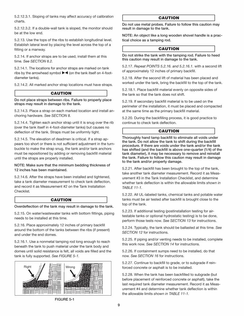
tank is fully supported. See FIGURE 5-1.
FIGuRE 5-1
Do not use metal probes. Failure to follow this caution mayresult in damage to the tank.
NOTE: An object like a long wooden shovel handle is a prac-
tical choice as a tamping rod.
Do not strike the tank with the tamping rod. Failure to heedthis caution may result in damage to the tank.
5.2.17. Repeat POINTS 5.2.16. and 5.2.16.1. with a second lift
of approximately 12 inches of primary backfill.
5.2.18. After the second lift of material has been placed and
worked under the tank, bring the backfill to the top of the tank.
5.2.18.1. Place backfill material evenly on opposite sides of
the tank so that the tank does not shift.
5.2.19. If secondary backfill material is to be used on the
perimeter of the installation, it must be placed and compacted
at the same time as the primary backfill material.
5.2.20. During the backfilling process, it is good practice to
continue to check tank deflection.
Thoroughly hand tamp backfill to eliminate all voids underthe tank. Do not allow the tank to shift during the backfillprocedure. If there are voids under the tank and/or the tankhas shifted (and the backfill is above one-quarter (1/4) of thetank diameter), it may be necessary to remove and reinstallthe tank. Failure to follow this caution may result in damageto the tank and/or property damage.
5.2.21. After backfill has been brought to the top of the tank,
take another tank diameter measurement. Record it as Meas-
urement #3 in the Tank Installation Checklist, and determine
whether tank deflection is within the allowable limits shown in
TABLE 11-1.
5.2.22. All UL-labeled tanks, chemical tanks and potable water
tanks must be air tested after backfill is brought close to the
top of the tank.
5.2.23. If additional testing (postinstallation testing for air-
testable tanks or optional hydrostatic testing) is to be done,
perform those tests now. See SECTION 13 for instructions.
5.2.24. Typically, the tank should be ballasted at this time. See
SECTION 12 for instructions.
5.2.25. If piping and/or venting needs to be installed, complete
this work now. See SECTION 14 for instructions.
5.2.26. If containment sumps need to be installed, do that
now. See SECTION 16 for instructions.
5.2.27. Continue to backfill to grade, or to subgrade if rein-
forced concrete or asphalt is to be installed.
5.2.28. When the tank has been backfilled to subgrade (but
before placement of reinforced concrete or asphalt), take the
last required tank diameter measurement. Record it as Meas-
urement #4 and determine whether tank deflection is within
the allowable limits shown in TABLE 11-1.
Right Wrong
9
5.2.28.1. Subtract Measurement #4 from Measurement #1 and record
it as the Deflection Measurement on the Tank Installation Checklist.
5.2.29. Install reinforced concrete or asphalt, if used, at this
time. See SECTION 7.4.
5.2.29.1. The cover depth must meet the appropriate minimum
specified in SECTION 7.4.
5.2.29.2. For installations in traffic conditions, all secondary
backfill used as subgrade backfill must be compacted with a
hand-guided, vibrating-plate, mechanical compactor.
5.2.30. If the tank has a monitoring system, after backfilling is
completed and after top slab is in place (if used), perform nec-
essary monitoring checks. See SECTION 15.
5.2.31. Complete the Tank Installation Checklist.
5.3. Wet-Hole InstallatIon5.3.1. Follow the dry-hole installation instructions (SECTION
5.2.) with the modifications listed below.
5.3.2. Perform POINTS 5.2.1. through 5.2.4.4. of the dry-hole
installation instructions.
5.3.3. Before performing POINT 5.2.5. of the dry-hole in stal la-
tion instructions, pump water from the excavation hole and
continue pumping to maintain minimum water level during
tank installation.
5.3.3.1. Attempt to maintain the water level below the top of
the bedding materials until the tank can be fully backfilled and
ballasted.
5.3.4. Proceed with POINTS 5.2.5. through 5.2.9.1. of the dry-
hole installation instructions.
5.3.4.1. In high-water conditions, when Xerxes’ preferred Man-
Out-of-Hole (MOH) anchoring method is not available or pos-
sible, see SECTION 8.8. for an alternate method.
5.3.5. Proceed with POINTS 5.2.10. through 5.2.12.3.2. of the
dry-hole installation instructions.
5.3.6. In high-water conditions, where it is not possible to
maintain the water level below the top of the bedding material
during the entire installation, partially ballast the tank to firmly
seat the tank into the bedding material and to keep it from
floating. See SECTION 12 for instructions.
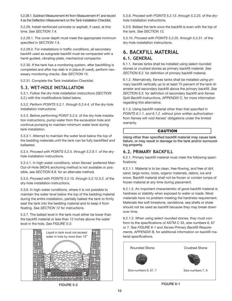
5.3.7. The ballast level in the tank must either be lower than
the backfill material or less than 12 inches above the water
level in the hole. See FIGURE 5-2.
FIGuRE 5-2
5.3.8. Proceed with POINTS 5.2.13. through 5.2.23. of the dry-
hole installation instructions.
5.3.9. Ballast the tank once the backfill is even with the top of
the tank. See SECTION 12.
5.3.10. Proceed with POINTS 5.2.25. through 5.2.31. of the
dry-hole installation instructions.
6. BaCKFIll MaterIal6.1. general6.1.1. Xerxes tanks shall be installed using select rounded
stones or crushed stones as primary backfill material. See
SECTION 6.2. for definition of primary backfill material.
6.1.2. Alternatively, Xerxes tanks shall be installed using pri-
mary backfill vertically up to at least 75 percent of the tank di-
ameter and secondary backfill above the primary backfill. See
SECTION 6.3. for definition of secondary backfill and Xerxes
Split Backfill Instructions, APPENDIX C, for more information
regarding this alternative.
6.1.3. Using backfill material other than that specified in
POINTS 6.1.1. and 6.1.2. without prior written authorization
from Xerxes will void Xerxes’ obligations under the limited
warranty.
using other than specified backfill material may cause tankfailure, or may result in damage to the tank and/or surround-ing property.
6.2. prIMarY BaCKFIll6.2.1. Primary backfill material must meet the following spec i-
fi ca tions:
6.2.1.1. Material is to be clean, free-flowing, and free of dirt,
sand, large rocks, roots, organic materials, debris, ice and
snow. Backfill material shall not be frozen or contain lumps of
frozen material at any time during placement.
6.2.1.2. An important characteristic of good backfill material is
hardness or stability when exposed to water or loads. Most
materials have no problem meeting the hardness requirement.
Materials like soft limestone, sandstone, sea shells or shale
should not be used as backfill because they may break down
over time.
6.2.1.3. When using select rounded stones, they must con-
form to the specifications of ASTM C 33, size numbers 6, 67
or 7. See FIGURE 6-1 and Xerxes Primary Backfill Require-
ments, APPENDIX B, for additional information on backfill ma-
terial specifications.
FIGuRE 6-1
Liquid in tank must not exceed
water in hole by more than 12"
Rounded Stone Crushed Stone
Size numbers 6, 67, 7 Size numbers 7, 8
10
6.2.1.4. When using select crushed stones, they must con-
form to the specifications of ASTM C 33, size numbers 7 or 8.
See FIGURE 6-1 and Xerxes Primary Backfill Requirements,
APPENDIX B, for additional information on backfill material
specifications.
6.2.2. Xerxes recommends that the supplier of backfill material
provides written certification that the material conforms to
ASTM C 33, ASTM D 448, AASHTO M 43, and any other appli-
cable specifications.
6.2.3. If primary backfill material which meets these specifications
is not available, contact technical support at Xerxes Minneapolis,
MN, for information on alternate materials, installation instructions
for alternate materials and the process for approval.
6.3. seCondarY BaCKFIll6.3.1. Material is to be clean, free-flowing, and free of large
rocks, roots, organic materials, debris, ice and snow. Backfill
material shall not be frozen or contain lumps of frozen material
at any time during installation.
6.3.2. Material must be compacted to achieve a minimum of
85 percent standard proctor density.
6.3.2.1. Do not use rammer-type compactors over the top of
the tank.
6.3.3. Material must be installed in 12-inch to 24-inch lifts
compatible with the compaction equipment used.
6.3.4. In some conditions, frost heave may be encountered
when using secondary backfill. Therefore, consider any frost-
related problems that may occur.
6.3.5. Specifications for secondary backfill material and com-
paction above the filter-fabric layer may be determined by the
requirements of the piping, surface slab or roadway.
6.3.6. Refer to applicable codes or standards for base course
and sub-base course material and compaction requirements.
6.3.7. The following are examples of acceptable secondary
backfill material:
6.3.7.1. clean native backfill
6.3.7.2. coarse sand or gravel.
6.3.8. One hundred percent (100%) of all backfill material must
pass through a 1-inch sieve.
6.3.9. Install a layer of geotextile filter fabric over the entire surface
of primary backfill material before secondary backfill is placed. See
SECTION 9 for information regarding geotextile fabric.
6.3.9.1. All joints in the filter fabric must be overlapped a mini-
mum of 12 inches.
6.3.9.2. Geotextile fabric must overlap onto the tank and exca-
vation surface a minimum of 12 inches.
6.3.10. See Xerxes Split Backfill Instructions, APPENDIX C, for
more information regarding this alternative.
7. eXCaVatIon reQuIreMents
Follow OSHA regulations for tank excavations. Collapse ofex ca va tion walls could result in death or serious injury.
7.1. general7.1.1. The installing contractor must take all necessary pre-
cautions in or near a tank excavation. These precautions
should include but are not limited to the following:
7.1.1.1. Locate and protect any utility installations near the ex-
cavation before opening the excavation.
7.1.1.2. Secure the walls of the excavation.
7.1.1.3. Prevent exposure to hazardous fumes from the excavation.
7.1.1.4. Avoid hazards associated with water accumulation in
the excavation.
7.1.1.5. Erect barricades, etc., to prevent unauthorized vehicle
or pedestrian traffic.
7.1.1.6. Inspect, a minimum of once a day, the excavation and
surrounding area during the entire installation process.
7.1.2. For additional information on excavation, trenching and
shoring safety practices, consult OSHA’s Standard, Part 1926,
Subpart P (Excavations), 650-652; and “Fall Protection Rules
and Regulations.”
7.1.3. The minimum clearance dimensions given in this section
are important to the successful installation of a tank.
7.1.3.1. Additional clearances may be necessary due to fed-
eral, state or local regulations, safety requirements or opera-
tional requirements. Follow all applicable regulations and
safety practices.
7.1.3.2. For additional requirements and specifications, con-
sult all applicable federal, state and local codes and regula-
tions. See SECTION 1 for additional information.
7.2. eXCaVatIon and tanK loCatIon7.2.1. Xerxes recommends that the tank owner seek the advice of
a local foundation professional engineer to determine the proper
placement of a tank excavation near any existing structure(s).
Improper placement of the excavation may result in damageto the tank and/or property damage.
7.2.2. The tank owner and/or the owner's technical represen-
tative is responsible for determining the proper placement of a
tank excavation.
7.2.3. In general terms, the size of the excavation is deter-
mined by:
7.2.3.1. the number of tanks to be installed
7.2.3.2. the size of the tanks to be installed.
7.2.4. The location of a tank can be affected by the location of
nearby structures. When selecting a tank site, care must be
taken to avoid undermining the foundations of existing struc-
tures or new buildings to be constructed. See FIGURE 7-1.
11
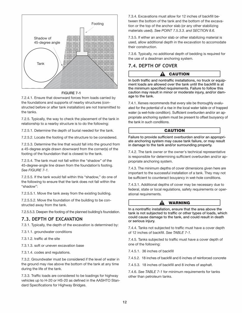
FIGuRE 7-1
7.2.4.1. Ensure that downward forces from loads carried by
the foundations and supports of nearby structures (con-
structed before or after tank installation) are not transmitted to
the tanks.
7.2.5. Typically, the way to check the placement of the tank in
relationship to a nearby structure is to do the following:
7.2.5.1. Determine the depth of burial needed for the tank.
7.2.5.2. Locate the footing of the structure to be considered.
7.2.5.3. Determine the line that would fall into the ground from
a 45-degree angle drawn downward from the corner(s) of the
footing of the foundation that is closest to the tank.
7.2.5.4. The tank must not fall within the “shadow” of the
45-degree-angle line drawn from the foundation’s footing.
See FIGURE 7-1.
7.2.5.5. If the tank would fall within this “shadow,” do one of
the following to ensure that the tank does not fall within the
“shadow”:
7.2.5.5.1. Move the tank away from the existing building.
7.2.5.5.2. Move the foundation of the building to be con-
structed away from the tank.
7.2.5.5.3. Deepen the footing of the planned building’s foundation.
7.3. deptH oF eXCaVatIon7.3.1. Typically, the depth of the excavation is determined by:
7.3.1.1. groundwater conditions
7.3.1.2. traffic at the site
7.3.1.3. soft or uneven excavation base
7.3.1.4. codes and regulations.
7.3.2. Groundwater must be considered if the level of water in
the ground may rise above the bottom of the tank at any time
during the life of the tank.
7.3.3. Traffic loads are considered to be loadings for highway
vehicles up to H-20 or HS-20 as defined in the AASHTO Stan-
dard Specifications for Highway Bridges.
7.3.4. Excavations must allow for 12 inches of backfill be-
tween the bottom of the tank and the bottom of the excava-
tion or the top of the anchor slab (or any other stabilizing
materials used). See POINT 7.5.3.3. and SECTION 8.6.
7.3.5. If either an anchor slab or other stabilizing material is
used, allow additional depth in the excavation to accomodate
their construction.
7.3.6. Typically, no additional depth of bedding is required for
the use of a deadman anchoring system.
7.4. deptH oF CoVer
In both traffic and nontraffic installations, no truck or equip-ment loads are allowed over the tank until the backfill is atthe minimum specified requirements. Failure to follow thiscaution may result in minor or moderate injury, and/or dam-age to the tank.
7.4.1. Xerxes recommends that every site be thoroughly evalu-
ated for the potential of a rise in the local water table or of trapped
water (a wet-hole condition). Sufficient overburden and/or an ap-
pro pri ate anchoring system must be present to offset buoy an cy of
the tank in such conditions.
Failure to provide sufficient overburden and/or an appropri-ate anchoring system may cause tank failure, or may resultin damage to the tank and/or surrounding property.
7.4.2. The tank owner or the owner's technical representative
is responsible for determining sufficient overburden and/or ap-
propriate anchoring system.
7.4.3. The minimum depths of cover dimensions given here are
important to the successful installation of a tank. They may not
be sufficient to counteract bouyancy in wet-hole conditions.
7.4.3.1. Additional depths of cover may be necessary due to
federal, state or local regulations, safety requirements or oper-
ational requirements.
In a nontraffic installation, ensure that the area above thetank is not subjected to traffic or other types of loads, whichcould cause damage to the tank, and could result in deathor serious injury.
7.4.4. Tanks not subjected to traffic must have a cover depth
of 12 inches of backfill. See TABLE 7-1.
7.4.5. Tanks subjected to traffic must have a cover depth of
one of the following:
7.4.5.1. 36 inches of backfill
7.4.5.2. 18 inches of backfill and 6 inches of reinforced concrete
7.4.5.3. 18 inches of backfill and 8 inches of asphalt.
7.4.6. See TABLE 7-1 for minimum requirements for tanks
other than petroleum tanks.
Shadow of 45-degree angle
Tank
Footing
12
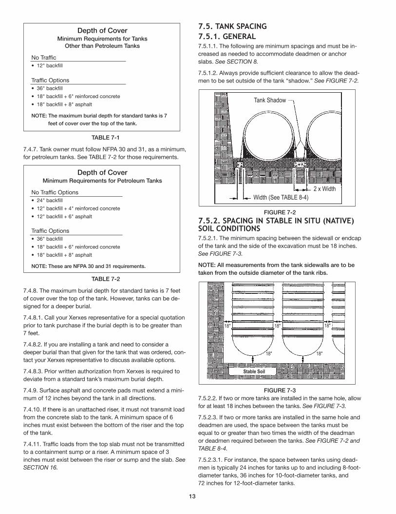
TABLE 7-1
7.4.7. Tank owner must follow NFPA 30 and 31, as a minimum,
for petroleum tanks. See TABLE 7-2 for those requirements.
TABLE 7-2
7.4.8. The maximum burial depth for standard tanks is 7 feet
of cover over the top of the tank. However, tanks can be de-
signed for a deeper burial.
7.4.8.1. Call your Xerxes representative for a special quotation
prior to tank purchase if the burial depth is to be greater than
7 feet.
7.4.8.2. If you are installing a tank and need to consider a
deeper burial than that given for the tank that was ordered, con-
tact your Xerxes rep re sen ta tive to discuss available options.
7.4.8.3. Prior written authorization from Xerxes is required to
deviate from a standard tank’s maximum burial depth.
7.4.9. Surface asphalt and concrete pads must extend a mini-
mum of 12 inches beyond the tank in all directions.
7.4.10. If there is an unattached riser, it must not transmit load
from the concrete slab to the tank. A minimum space of 6
inches must exist between the bottom of the riser and the top
of the tank.
7.4.11. Traffic loads from the top slab must not be transmitted
to a containment sump or a riser. A minimum space of 3
inches must exist between the riser or sump and the slab. See
SECTION 16.
7.5. tanK spaCIng
7.5.1. general7.5.1.1. The following are minimum spacings and must be in-
creased as needed to accommodate deadmen or anchor
slabs. See SECTION 8.
7.5.1.2. Always provide sufficient clearance to allow the dead-
men to be set outside of the tank “shadow.” See FIGURE 7-2.
FIGuRE 7-2
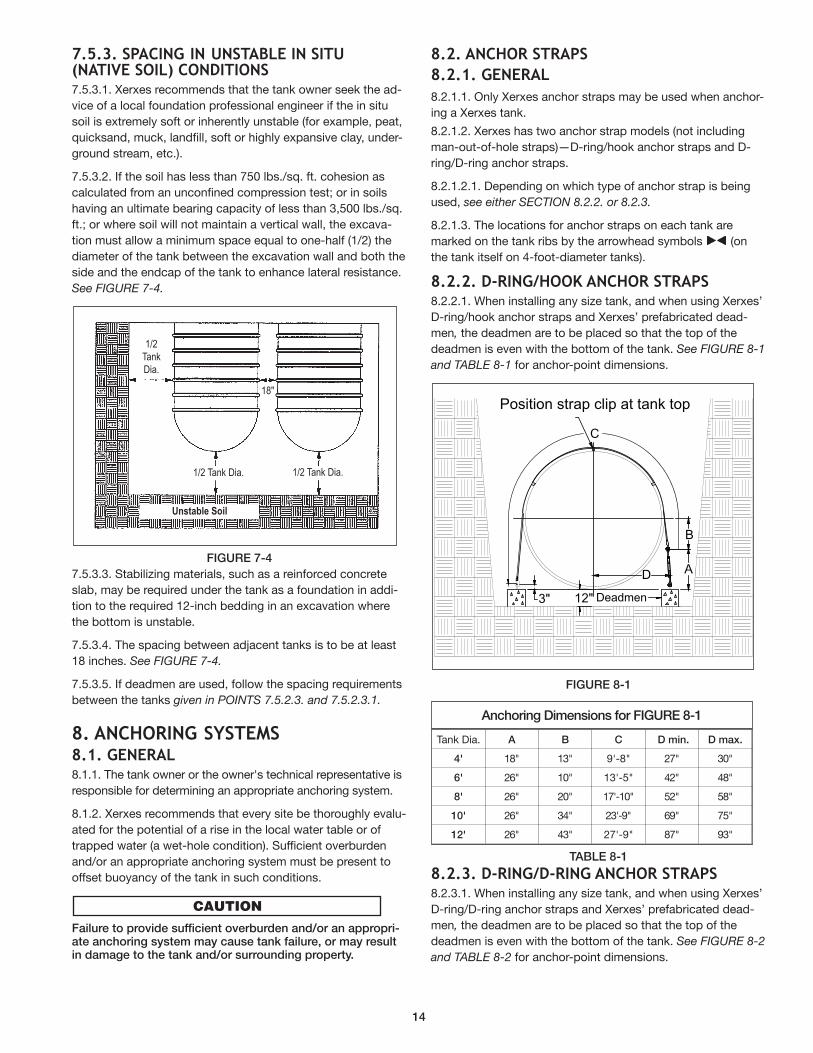
7.5.2. spaCIng In staBle In sItu (natIVe)soIl CondItIons7.5.2.1. The minimum spacing between the sidewall or endcap
of the tank and the side of the excavation must be 18 inches.
See FIGURE 7-3.
NOTE: All measurements from the tank sidewalls are to be
taken from the outside diameter of the tank ribs.
FIGuRE 7-3
7.5.2.2. If two or more tanks are installed in the same hole, allow
for at least 18 inches between the tanks. See FIGURE 7-3.
7.5.2.3. If two or more tanks are installed in the same hole and
deadmen are used, the space between the tanks must be
equal to or greater than two times the width of the deadman
or deadmen required between the tanks. See FIGURE 7-2 and
TABLE 8-4.
7.5.2.3.1. For instance, the space between tanks using dead-
men is typically 24 inches for tanks up to and including 8-foot-
diameter tanks, 36 inches for 10-foot-diameter tanks, and
72 inches for 12-foot-diameter tanks.
Depth of CoverMinimum Requirements for Petroleum Tanks
No Traffic Options
• 24" backfill
• 12" backfill + 4" reinforced concrete
• 12" backfill + 6" asphalt
Traffic Options
• 36" backfill
• 18" backfill + 6" reinforced concrete
• 18" backfill + 8" asphalt
NOTE: These are NFPA 30 and 31 requirements.
T ank Shadow
Width (See TABLE 8-4)
2 x Width
18" 18" 18"
Stable Soil
18"18"
Depth of CoverMinimum Requirements for Tanks
Other than Petroleum Tanks
No Traffic
• 12" backfill
Traffic Options
• 36" backfill
• 18" backfill + 6" reinforced concrete
• 18" backfill + 8" asphalt
NOTE: The maximum burial depth for standard tanks is 7
feet of cover over the top of the tank.
13
7.5.3. spaCIng In unstaBle In sItu(natIVe soIl) CondItIons7.5.3.1. Xerxes recommends that the tank owner seek the ad-
vice of a local foundation professional engineer if the in situ
soil is extremely soft or inherently unstable (for example, peat,
quicksand, muck, landfill, soft or highly expansive clay, under-
ground stream, etc.).
7.5.3.2. If the soil has less than 750 lbs./sq. ft. cohesion as
calculated from an unconfined compression test; or in soils
having an ultimate bearing capacity of less than 3,500 lbs./sq.
ft.; or where soil will not maintain a vertical wall, the excava-
tion must allow a minimum space equal to one-half (1/2) the
diameter of the tank between the excavation wall and both the
side and the endcap of the tank to enhance lateral resistance.
See FIGURE 7-4.
FIGuRE 7-4
7.5.3.3. Stabilizing materials, such as a reinforced concrete
slab, may be required under the tank as a foundation in addi-
tion to the required 12-inch bedding in an excavation where
the bottom is unstable.
7.5.3.4. The spacing between adjacent tanks is to be at least
18 inches. See FIGURE 7-4.
7.5.3.5. If deadmen are used, follow the spacing requirements
between the tanks given in POINTS 7.5.2.3. and 7.5.2.3.1.
8. anCHorIng sYsteMs8.1. general 8.1.1. The tank owner or the owner's technical representative is
responsible for determining an appropriate anchoring system.
8.1.2. Xerxes recommends that every site be thoroughly evalu-
ated for the potential of a rise in the local water table or of
trapped water (a wet-hole condition). Sufficient overburden
and/or an ap pro pri ate anchoring system must be present to
offset buoy an cy of the tank in such conditions.
Failure to provide sufficient overburden and/or an appropri-ate anchoring system may cause tank failure, or may resultin damage to the tank and/or surrounding property.
8.2. anCHor straps
8.2.1. general
8.2.1.1. Only Xerxes anchor straps may be used when anchor-
ing a Xerxes tank.
8.2.1.2. Xerxes has two anchor strap models (not including
man-out-of-hole straps)—D-ring/hook anchor straps and D-
ring/D-ring anchor straps.
8.2.1.2.1. Depending on which type of anchor strap is being
used, see either SECTION 8.2.2. or 8.2.3.
8.2.1.3. The locations for anchor straps on each tank are
marked on the tank ribs by the arrowhead symbols (on
the tank itself on 4-foot-diameter tanks).
8.2.2. d-rIng/HooK anCHor straps8.2.2.1. When installing any size tank, and when using Xerxes’
D-ring/hook anchor straps and Xerxes’ prefabricated dead-
men, the deadmen are to be placed so that the top of the
deadmen is even with the bottom of the tank. See FIGURE 8-1
and TABLE 8-1 for anchor-point dimensions.
FIGuRE 8-1
TABLE 8-1
8.2.3. d-rIng/d-rIng anCHor straps8.2.3.1. When installing any size tank, and when using Xerxes’
D-ring/D-ring anchor straps and Xerxes’ prefabricated dead-
men, the deadmen are to be placed so that the top of the
deadmen is even with the bottom of the tank. See FIGURE 8-2
and TABLE 8-2 for anchor-point dimensions.
1/2TankDia.
1/2 Tank Dia. 1/2 Tank Dia.
Unstable Soil
18"Position strap clip at tank top
Deadmen 3" 12"
D A
B
C
Tank Dia. A B C D min. D max.
4' 18" 13" 9'-8" 27" 30"
6' 26" 10" 13'-5" 42" 48"
8' 26" 20" 17'-10" 52" 58"
10' 26" 34" 23'-9" 69" 75"
12' 26" 43" 27'-9" 87" 93"
Anchoring Dimensions for FIGuRE 8-1
14
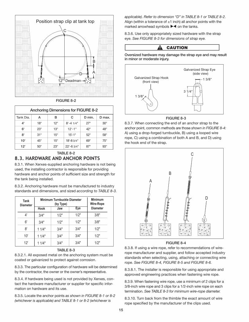
FIGuRE 8-2
TABLE 8-2
8.3. HardWare and anCHor poInts8.3.1. When Xerxes-supplied anchoring hardware is not being
used, the installing contractor is responsible for providing
hardware and anchor points of sufficient size and strength for
the tank being installed.
8.3.2. Anchoring hardware must be manufactured to industry
standards and dimensions, and sized according to TABLE 8-3.
TABLE 8-3
8.3.2.1. All exposed metal on the anchoring system must be
coated or gal va nized to protect against corrosion.
8.3.3. The particular configuration of hardware will be de ter mined
by the contractor, the owner or the owner’s rep re sen ta tive.
8.3.4. If hardware being used is not provided by Xerxes, con-
tact the hardware manufacturer or supplier for specific infor-
mation on hardware and its use.
8.3.5. Locate the anchor points as shown in FIGURE 8-1 or 8-2
(whichever is applicable) and TABLE 8-1 or 8-2 (whichever is
applicable). Refer to dimension “D” in TABLE 8-1 or TABLE 8-2.
Align (within a tolerance of ±1 inch) all anchor points with the
marked arrowhead symbols on the tanks.
8.3.6. Use only appropriately sized hardware with the strap
eye. See FIGURE 8-3 for dimen sions of strap eye.
Oversized hardware may damage the strap eye and may resultin minor or moderate injury.
FIGuRE 8-3
8.3.7. When connecting the end of an anchor strap to the
anchor point, common methods are those shown in FIGURE 8-4:
A) using a drop-forged turnbuckle, B) using a looped wire
rope, C) using a combination of both A and B, and D) using
the hook end of the strap.
FIGuRE 8-4
8.3.8. If using a wire rope, refer to recommendations of wire-
rope manufacturer and supplier, and follow accepted industry
standards when selecting, using, attaching or connecting wire
rope. See FIGURE 8-4, FIGURE 8-5 and FIGURE 8-6.
8.3.8.1. The in stall er is re spon si ble for us ing ap pro pri ate and
ap proved en gi neer ing prac tic es when fas ten ing wire rope.
8.3.9. When fastening wire rope, use a minimum of 2 clips for a
3/8-inch wire rope and 3 clips for a 1/2-inch wire rope on each
termination. See TABLE 8-3 for minimum wire-rope diameter.
8.3.10. Turn back from the thimble the exact amount of wire
rope specified by the manufacturer of the clips used.
Tank Dia. A B C D min. D max.
4' 18" 12" 8'-4 1/4" 27" 30"
6' 23" 13" 12'-1" 42" 48"
8' 31" 15" 15'-1" 52" 58"
10' 45" 15" 18'-8 3/4" 69" 75"
12' 50" 23" 22'-6 3/4" 87" 93"
Anchoring Dimensions for FIGuRE 8-2
Tank
Diameter
4'
6'
8'
10'
12'
Hook
3/4"
3/4"
1 1/4"
1 1/4"
1 1/4"
Minimum Turnbuckle Diameter
(by Type)
Jaw
1/2"
1/2"
3/4"
3/4"
3/4"
Minimum
Wire-Rope
Diameter
3/8"
3/8"
1/2"
1/2"
1/2"
Eye
1/2"
1/2"
3/4"
3/4"
3/4"
Galvanized Strap Eye (side view)
3 1/4"1 3/8"
1 3/8"Galvanized Strap Hook (front view)
AB
C
D
Position strap clip at tank top
Deadman
C
B
A D
12"
15
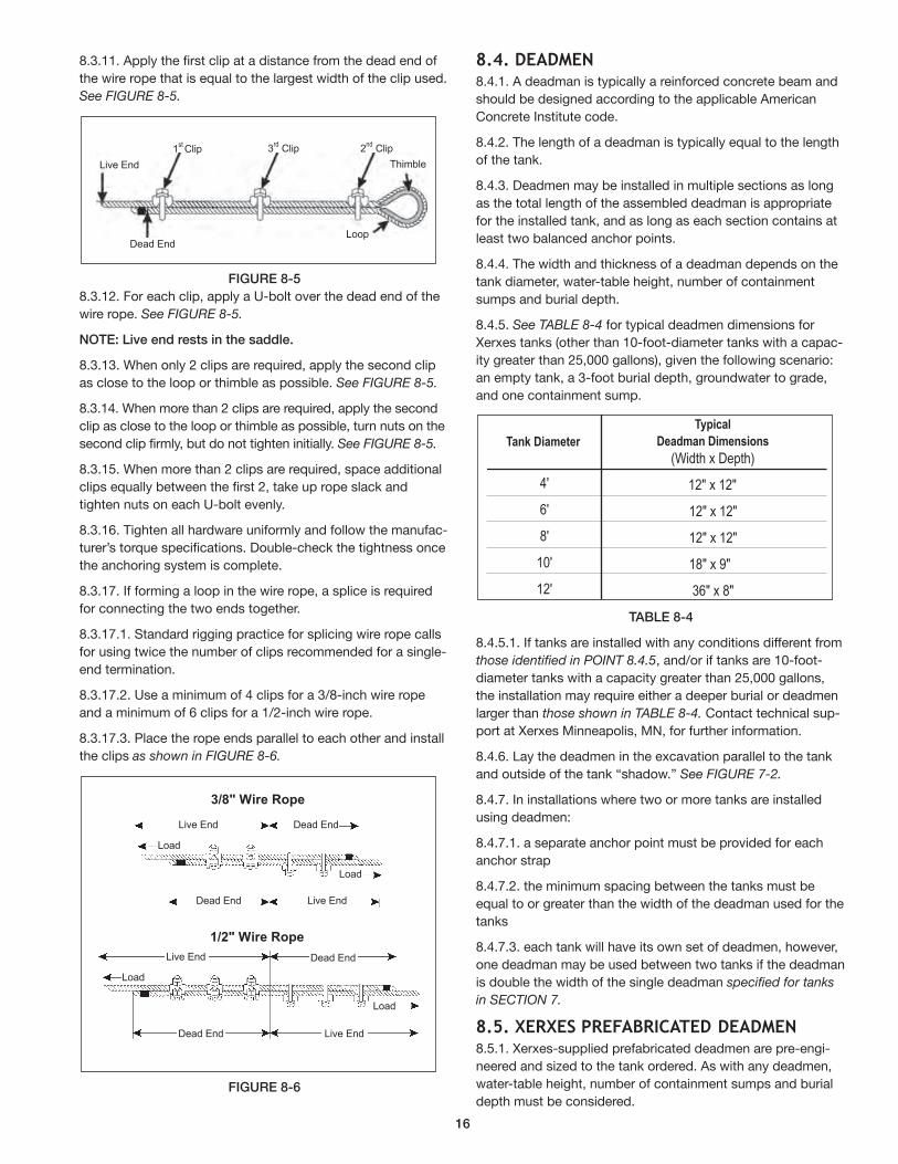
8.3.11. Apply the first clip at a distance from the dead end of
the wire rope that is equal to the largest width of the clip used.
See FIGURE 8-5.
FIGuRE 8-5
8.3.12. For each clip, apply a U-bolt over the dead end of the
wire rope. See FIGURE 8-5.
NOTE: Live end rests in the saddle.
8.3.13. When only 2 clips are required, apply the second clip
as close to the loop or thimble as possible. See FIGURE 8-5.
8.3.14. When more than 2 clips are required, apply the second
clip as close to the loop or thimble as possible, turn nuts on the
second clip firmly, but do not tighten initially. See FIGURE 8-5.
8.3.15. When more than 2 clips are required, space additional
clips equally between the first 2, take up rope slack and
tighten nuts on each U-bolt evenly.
8.3.16. Tighten all hardware uniformly and follow the manufac-
turer’s torque specifications. Double-check the tightness once
the anchoring system is complete.
8.3.17. If forming a loop in the wire rope, a splice is required
for connecting the two ends together.
8.3.17.1. Standard rigging practice for splicing wire rope calls
for using twice the number of clips recommended for a single-
end termination.
8.3.17.2. Use a minimum of 4 clips for a 3/8-inch wire rope
and a minimum of 6 clips for a 1/2-inch wire rope.
8.3.17.3. Place the rope ends parallel to each other and install
the clips as shown in FIGURE 8-6.
FIGuRE 8-6
8.4. deadMen 8.4.1. A deadman is typically a reinforced concrete beam and
should be designed according to the applicable American
Concrete Institute code.
8.4.2. The length of a deadman is typically equal to the length
of the tank.
8.4.3. Deadmen may be installed in multiple sections as long
as the total length of the assembled deadman is appropriate
for the installed tank, and as long as each section contains at
least two balanced anchor points.
8.4.4. The width and thickness of a deadman depends on the
tank diameter, water-table height, number of containment
sumps and burial depth.
8.4.5. See TABLE 8-4 for typical deadmen dimensions for
Xerxes tanks (other than 10-foot-diameter tanks with a capac-
ity greater than 25,000 gallons), given the following scenario:
an empty tank, a 3-foot burial depth, groundwater to grade,
and one containment sump.
TABLE 8-4
8.4.5.1. If tanks are installed with any conditions different from
those identified in POINT 8.4.5, and/or if tanks are 10-foot-
diameter tanks with a capacity greater than 25,000 gallons,
the installation may require either a deeper burial or deadmen
larger than those shown in TABLE 8-4. Contact technical sup-
port at Xerxes Minneapolis, MN, for further information.
8.4.6. Lay the deadmen in the excavation parallel to the tank
and outside of the tank “shadow.” See FIGURE 7-2.
8.4.7. In installations where two or more tanks are installed
using deadmen:
8.4.7.1. a separate anchor point must be provided for each
anchor strap
8.4.7.2. the minimum spacing between the tanks must be
equal to or greater than the width of the deadman used for the
tanks
8.4.7.3. each tank will have its own set of deadmen, however,
one deadman may be used between two tanks if the dead man
is double the width of the single deadman specified for tanks
in SECTION 7.
8.5. XerXes preFaBrICated deadMen 8.5.1. Xerxes-supplied prefabricated deadmen are pre-engi-
neered and sized to the tank ordered. As with any deadmen,
water-table height, number of containment sumps and burial
depth must be considered.
Dead End
Live End
Loop
1stClip 3
rdClip 2
ndClip
Thimble
1/2" Wire Rope
3/8" Wire Rope
Dead EndLive End
Load
Dead End Live End
Load
Dead EndLive End
Load
Dead End Live End
Load
4'
6'
8'
10'
12'
TypicalDeadman Dimensions
(Width x Depth)
12" x 12"
12" x 12"
12" x 12"
18" x 9"
36" x 8"
Tank Diameter
16
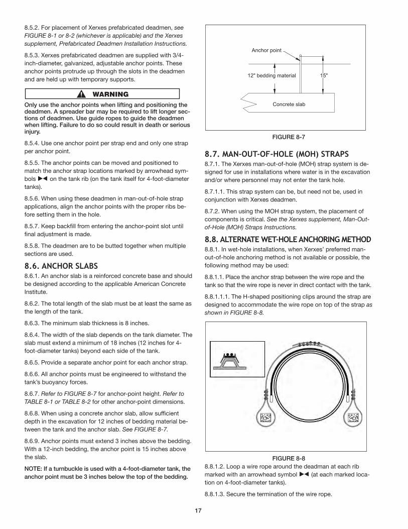
8.5.2. For placement of Xerxes prefabricated deadmen, see
FIGURE 8-1 or 8-2 (whichever is applicable) and the Xerxes
supplement, Prefabricated Deadmen Installation Instructions.
8.5.3. Xerxes prefabricated deadmen are supplied with 3/4-
inch-diameter, galvanized, adjustable anchor points. These
anchor points protrude up through the slots in the deadmen
and are held up with temporary supports.
Only use the anchor points when lifting and positioning thedeadmen. A spreader bar may be required to lift longer sec-tions of deadmen. use guide ropes to guide the deadmenwhen lifting. Failure to do so could result in death or seriousinjury.
8.5.4. Use one anchor point per strap end and only one strap
per anchor point.
8.5.5. The anchor points can be moved and positioned to
match the anchor strap locations marked by arrowhead sym-
bols on the tank rib (on the tank itself for 4-foot-diameter
tanks).
8.5.6. When using these deadmen in man-out-of-hole strap
applications, align the anchor points with the proper ribs be-
fore setting them in the hole.
8.5.7. Keep backfill from entering the anchor-point slot until
final adjustment is made.
8.5.8. The deadmen are to be butted together when multiple
sections are used.
8.6. anCHor slaBs8.6.1. An anchor slab is a reinforced concrete base and should
be designed according to the applicable American Concrete
Institute.
8.6.2. The total length of the slab must be at least the same as
the length of the tank.
8.6.3. The minimum slab thickness is 8 inches.
8.6.4. The width of the slab depends on the tank diameter. The
slab must extend a minimum of 18 inches (12 inches for 4-
foot-diameter tanks) beyond each side of the tank.
8.6.5. Provide a separate anchor point for each anchor strap.
8.6.6. All anchor points must be engineered to withstand the
tank’s buoyancy forces.
8.6.7. Refer to FIGURE 8-7 for anchor-point height. Refer to
TABLE 8-1 or TABLE 8-2 for other anchor-point dimensions.
8.6.8. When using a concrete anchor slab, allow sufficient
depth in the excavation for 12 inches of bedding material be-
tween the tank and the anchor slab. See FIGURE 8-7.
8.6.9. Anchor points must extend 3 inches above the bedding.
With a 12-inch bedding, the anchor point is 15 inches above
the slab.
NOTE: If a turnbuckle is used with a 4-foot-diameter tank, the
anchor point must be 3 inches below the top of the bedding.
FIGuRE 8-7
8.7. Man-out-oF-Hole (MoH) straps8.7.1. The Xerxes man-out-of-hole (MOH) strap system is de-
signed for use in installations where water is in the ex ca va tion
and/or where personnel may not enter the tank hole.
8.7.1.1. This strap system can be, but need not be, used in
conjunction with Xerxes deadmen.
8.7.2. When using the MOH strap system, the placement of
components is critical. See the Xerxes supplement, Man-Out-
of-Hole (MOH) Straps Instructions.
8.8. alternate Wet-Hole anCHorIng MetHod 8.8.1. In wet-hole installations, when Xerxes’ preferred man-
out-of-hole anchoring method is not available or possible, the
following method may be used:
8.8.1.1. Place the anchor strap between the wire rope and the
tank so that the wire rope is never in direct contact with the tank.
8.8.1.1.1. The H-shaped positioning clips around the strap are
designed to accommodate the wire rope on top of the strap as
shown in FIGURE 8-8.
FIGuRE 8-8
8.8.1.2. Loop a wire rope around the deadman at each rib
marked with an arrowhead symbol (at each marked loca-
tion on 4-foot-diameter tanks).
8.8.1.3. Secure the termination of the wire rope.
15"
Anchor point
12" bedding material
Concrete slab
17
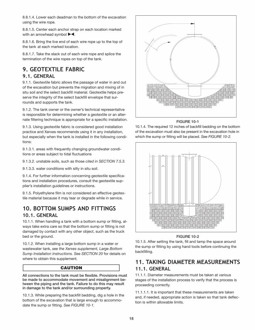
8.8.1.4. Lower each deadman to the bottom of the excavation
using the wire rope.
8.8.1.5. Center each anchor strap on each location marked
with an arrowhead symbol .
8.8.1.6. Bring the live end of each wire rope up to the top of
the tank at each marked location.
8.8.1.7. Take the slack out of each wire rope and splice the
termination of the wire ropes on top of the tank.
9. geoteXtIle FaBrIC9.1. general 9.1.1. Geotextile fabric allows the passage of water in and out
of the excavation but prevents the migration and mixing of in
situ soil and the select backfill material. Geotextile helps pre-
serve the integrity of the select backfill envelope that sur-
rounds and supports the tank.
9.1.2. The tank owner or the owner’s technical representative
is responsible for determining whether a geotextile or an alter-
nate filtering technique is appropriate for a specific installation.
9.1.3. Using geotextile fabric is considered good installation
practice and Xerxes recommends using it in any installation,
but especially when the tank is installed in the following condi-
tions:
9.1.3.1. areas with frequently changing groundwater condi-
tions or areas subject to tidal fluctuations
9.1.3.2. unstable soils, such as those cited in SECTION 7.5.3.
9.1.3.3. water conditions with silty in situ soil.
9.1.4. For further information concerning geotextile spec i fi ca-
tions and installation procedures, consult the geotextile sup-
plier’s installation guidelines or instructions.
9.1.5. Polyethylene film is not considered an effective geotex-
tile material because it may tear or degrade while in service.
10. BottoM suMps and FIttIngs10.1. general 10.1.1. When handling a tank with a bottom sump or fitting, al-
ways take extra care so that the bottom sump or fitting is not
damaged by contact with any other object, such as the truck
bed or the ground.
10.1.2. When installing a large bottom sump in a water or
wastewater tank, see the Xerxes supplement, Large Bottom
Sump Installation Instructions. See SECTION 20 for details on
where to obtain this supplement.
All connections to the tank must be flexible. Provisions mustbe made to accommodate movement and misalignment be-tween the piping and the tank. Failure to do this may resultin damage to the tank and/or surrounding property.
10.1.3. While preparing the backfill bedding, dig a hole in the
bottom of the excavation that is large enough to accommo-
date the sump or fitting. See FIGURE 10-1.
FIGuRE 10-1
10.1.4. The required 12 inches of backfill bedding on the bottom
of the excavation must also be present in the excavation hole in
which the sump or fitting will be placed. See FIGURE 10-2.
FIGuRE 10-2
10.1.5. After setting the tank, fill and tamp the space around
the sump or fitting by using hand tools before continuing the
backfilling.
11. taKIng dIaMeter MeasureMents11.1. general11.1.1. Diameter measurements must be taken at various
stages of the installation process to verify that the process is
proceeding correctly.
11.1.1.1. It is important that these measurements are taken
and, if needed, appropriate action is taken so that tank deflec-
tion is within allowable limits.
18
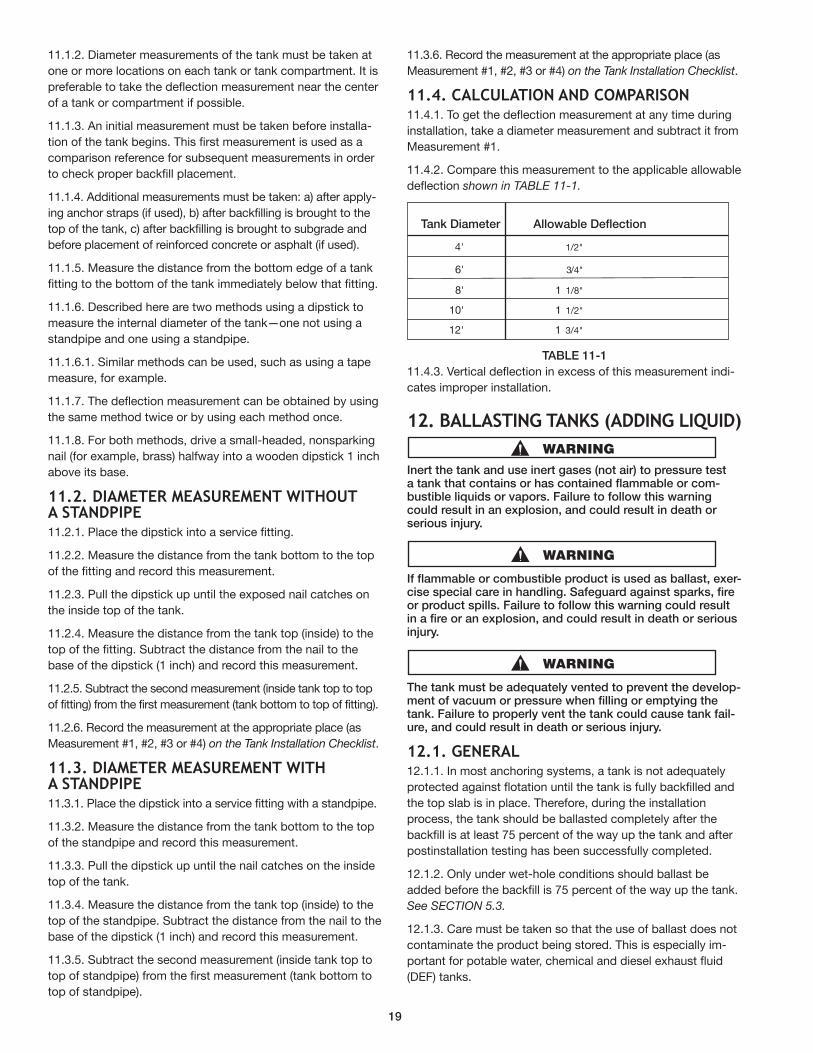
11.1.2. Diameter measurements of the tank must be taken at
one or more locations on each tank or tank compartment. It is
preferable to take the deflection measurement near the center
of a tank or compartment if possible.
11.1.3. An initial measurement must be taken before installa-
tion of the tank begins. This first measurement is used as a
comparison reference for subsequent measurements in order
to check proper backfill placement.
11.1.4. Additional measurements must be taken: a) after apply-
ing anchor straps (if used), b) after backfilling is brought to the
top of the tank, c) after backfilling is brought to subgrade and
before placement of reinforced concrete or asphalt (if used).
11.1.5. Measure the distance from the bottom edge of a tank
fitting to the bottom of the tank immediately below that fitting.
11.1.6. Described here are two methods using a dipstick to
measure the internal diameter of the tank—one not using a
standpipe and one using a standpipe .
11.1.6.1. Similar methods can be used, such as using a tape
measure, for example.
11.1.7. The deflection measurement can be obtained by using
the same method twice or by using each method once.
11.1.8. For both methods, drive a small-headed, nonsparking
nail (for example, brass) halfway into a wooden dipstick 1 inch
above its base.
11.2. dIaMeter MeasureMent WItHouta standpIpe11.2.1. Place the dipstick into a service fitting.
11.2.2. Measure the distance from the tank bottom to the top
of the fitting and record this measurement.
11.2.3. Pull the dipstick up until the exposed nail catches on
the inside top of the tank.
11.2.4. Measure the distance from the tank top (inside) to the
top of the fitting. Subtract the distance from the nail to the
base of the dipstick (1 inch) and record this measurement.
11.2.5. Subtract the second measurement (inside tank top to top
of fitting) from the first measurement (tank bottom to top of fitting).
11.2.6. Record the measurement at the appropriate place (as
Measurement #1, #2, #3 or #4) on the Tank Installation Checklist.
11.3. dIaMeter MeasureMent WItHa standpIpe11.3.1. Place the dipstick into a service fitting with a standpipe.
11.3.2. Measure the distance from the tank bottom to the top
of the standpipe and record this measurement.
11.3.3. Pull the dipstick up until the nail catches on the inside
top of the tank.
11.3.4. Measure the distance from the tank top (inside) to the
top of the standpipe. Subtract the distance from the nail to the
base of the dipstick (1 inch) and record this measurement.
11.3.5. Subtract the second measurement (inside tank top to
top of standpipe) from the first measurement (tank bottom to
top of standpipe).
11.3.6. Record the measurement at the appropriate place (as
Measurement #1, #2, #3 or #4) on the Tank Installation Checklist.
11.4. CalCulatIon and CoMparIson11.4.1. To get the deflection measurement at any time during
installation, take a diameter measurement and subtract it from
Measurement #1.
11.4.2. Compare this measurement to the applicable allowable
deflection shown in TABLE 11-1.
TABLE 11-1
11.4.3. Vertical deflection in excess of this measurement indi-
cates improper installation.
12. BallastIng tanKs (addIng lIQuId)
Inert the ta nk and use inert gases (not air) to pressure testa tank that contains or has contained flammable or com-bustible liquids or vapors. Failure to follow this warningcould result in an explosion, and could result in death orserious injury.
If flammable or combustible product is used as ballast, exer-cise special care in handling. Safeguard against sparks, fireor product spills. Failure to follow this warning could resultin a fire or an ex plo sion, and could result in death or seriousinjury.
The tank must be adequately vented to prevent the develop-ment of vacuum or pressure when filling or emptying thetank. Failure to properly vent the tank could cause tank fail-ure, and could result in death or serious injury.
12.1. general 12.1.1. In most anchoring systems, a tank is not adequately
protected against flotation until the tank is fully backfilled and
the top slab is in place. Therefore, during the installation
process, the tank should be ballasted completely after the
backfill is at least 75 percent of the way up the tank and after
postinstallation testing has been successfully complet ed.
12.1.2. Only under wet-hole conditions should ballast be
added before the backfill is 75 percent of the way up the tank.
See SECTION 5.3.
12.1.3. Care must be taken so that the use of ballast does not
contaminate the product being stored. This is especially im-
portant for potable water, chemical and diesel exhaust fluid
(DEF) tanks.
Tank Diameter Allowable Deflection
4' 1/2"
6' 3/4"
8' 1 1/8"
10' 1 1/2"
12' 1 3/4"
19
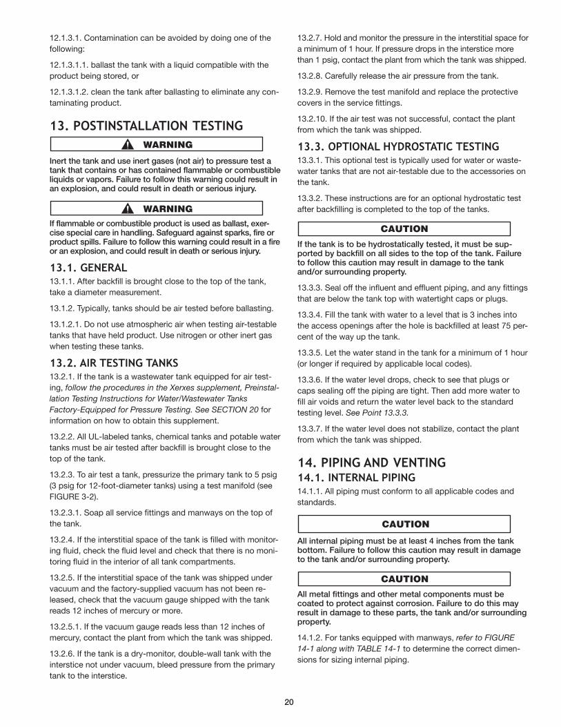
12.1.3.1. Contamination can be avoided by doing one of the
following:
12.1.3.1.1. ballast the tank with a liquid compatible with the
product being stored, or
12.1.3.1.2. clean the tank after ballasting to eliminate any con-
taminating product.
13. postInstallatIon testIng
Inert the tank and use inert gases (not air) to pressure test atank that contains or has contained flammable or combustibleliquids or vapors. Failure to follow this warning could result inan explosion, and could result in death or serious injury.
If flammable or combustible product is used as ballast, exer-cise special care in handling. Safeguard against sparks, fire orproduct spills. Failure to follow this warning could result in a fireor an ex plo sion, and could result in death or serious injury.
13.1. general13.1.1. After backfill is brought close to the top of the tank,
take a diameter measurement.
13.1.2. Typically, tanks should be air tested before ballasting.
13.1.2.1. Do not use atmospheric air when testing air-testable
tanks that have held product. Use nitrogen or other inert gas
when testing these tanks.
13.2. aIr testIng tanKs 13.2.1. If the tank is a wastewater tank equipped for air test-
ing, follow the procedures in the Xerxes supplement, Preinstal-
lation Testing Instructions for Water/Wastewater Tanks
Factory-Equipped for Pressure Testing. See SECTION 20 for
information on how to obtain this supplement.
13.2.2. All UL-labeled tanks, chemical tanks and potable water
tanks must be air tested after backfill is brought close to the
top of the tank.
13.2.3. To air test a tank, pressurize the primary tank to 5 psig
(3 psig for 12-foot-diameter tanks) using a test manifold (see
FIGURE 3-2).
13.2.3.1. Soap all service fittings and manways on the top of
the tank.
13.2.4. If the interstitial space of the tank is filled with monitor-
ing fluid, check the fluid level and check that there is no moni-
toring fluid in the interior of all tank compartments.
13.2.5. If the interstitial space of the tank was shipped under
vacuum and the factory-supplied vacuum has not been re-
leased, check that the vacuum gauge shipped with the tank
reads 12 inches of mercury or more.
13.2.5.1. If the vacuum gauge reads less than 12 inches of
mercury, contact the plant from which the tank was shipped.
13.2.6. If the tank is a dry-monitor, double-wall tank with the
interstice not under vacuum, bleed pressure from the primary
tank to the interstice.
13.2.7. Hold and monitor the pressure in the interstitial space for
a minimum of 1 hour. If pressure drops in the interstice more
than 1 psig, contact the plant from which the tank was shipped.
13.2.8. Carefully release the air pressure from the tank.
13.2.9. Remove the test manifold and replace the protective
covers in the service fittings.
13.2.10. If the air test was not successful, contact the plant
from which the tank was shipped.
13.3. optIonal HYdrostatIC testIng13.3.1. This optional test is typically used for water or waste-
water tanks that are not air-testable due to the accessories on
the tank.
13.3.2. These instructions are for an optional hydrostatic test
after backfilling is completed to the top of the tanks.
If the tank is to be hydrostatically tested, it must be sup-ported by backfill on all sides to the top of the tank. Failureto follow this caution may result in damage to the tankand/or surrounding property.
13.3.3. Seal off the influent and effluent piping, and any fittings
that are below the tank top with watertight caps or plugs.
13.3.4. Fill the tank with water to a level that is 3 inches into
the access openings after the hole is backfilled at least 75 per-
cent of the way up the tank.
13.3.5. Let the water stand in the tank for a minimum of 1 hour
(or longer if required by applicable local codes).
13.3.6. If the water level drops, check to see that plugs or
caps sealing off the piping are tight. Then add more water to
fill air voids and return the water level back to the standard
testing level. See Point 13.3.3.
13.3.7. If the water level does not stabilize, contact the plant
from which the tank was shipped.
14. pIpIng and VentIng14.1. Internal pIpIng 14.1.1. All piping must conform to all applicable codes and
standards.
All internal piping must be at least 4 inches from the tankbottom. Failure to follow this caution may result in damageto the tank and/or surrounding property.
All metal fittings and other metal components must becoated to protect against corrosion. Failure to do this mayresult in damage to these parts, the tank and/or surroundingproperty.
14.1.2. For tanks equipped with manways, refer to FIGURE
14-1 along with TABLE 14-1 to determine the correct dimen-
sions for sizing internal piping.
20
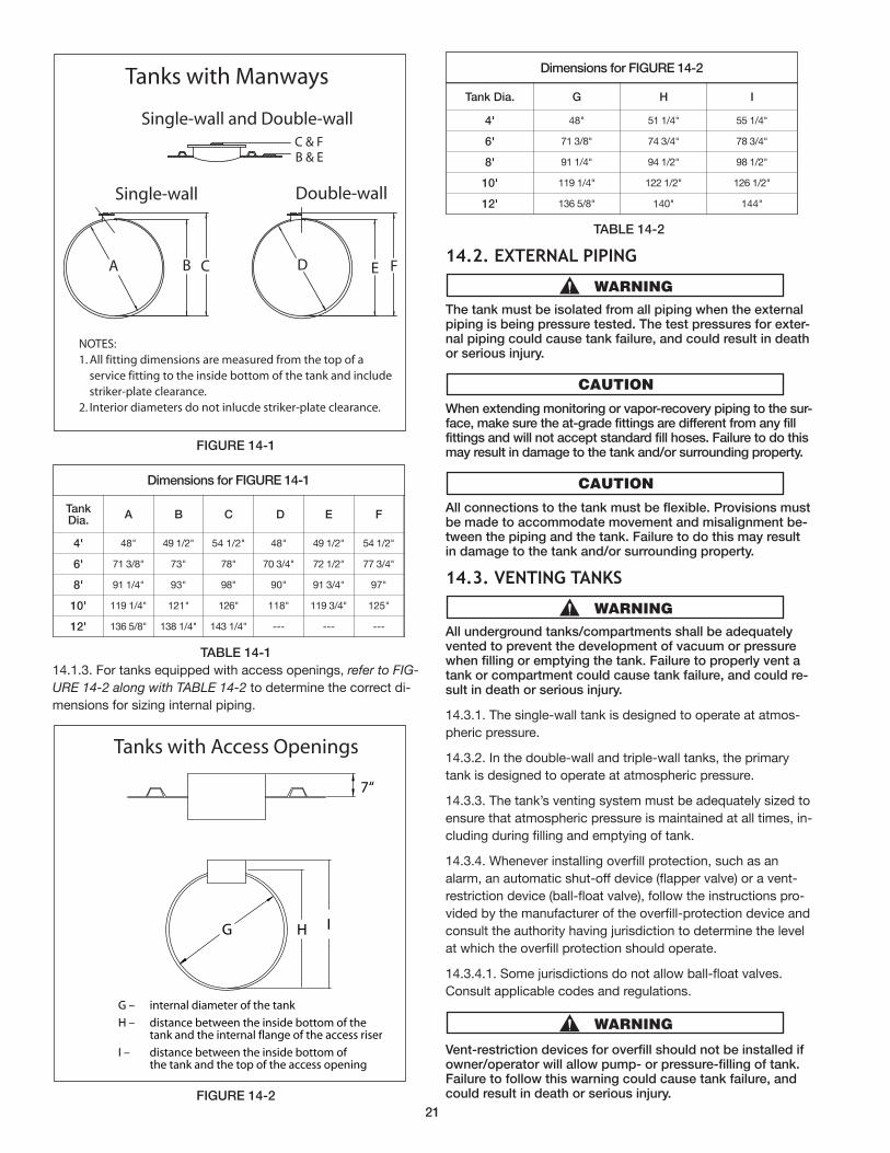
FIGuRE 14-1
TABLE 14-1
14.1.3. For tanks equipped with access openings, refer to FIG-
URE 14-2 along with TABLE 14-2 to determine the correct di-
mensions for sizing internal piping.
FIGuRE 14-2
TABLE 14-2
14.2. eXternal pIpIng
The tank must be isolated from all piping when the externalpiping is being pressure tested. The test pres sures for exter-nal piping could cause tank failure, and could result in deathor serious injury.
When extending monitoring or vapor-recovery piping to the sur-face, make sure the at-grade fittings are different from any fillfittings and will not accept standard fill hoses. Failure to do thismay result in damage to the tank and/or surrounding property.
All connections to the tank must be flexible. Provisions mustbe made to accommodate movement and misalignment be-tween the piping and the tank. Failure to do this may resultin damage to the tank and/or surrounding property.
14.3. VentIng tanKs
All underground tanks/compartments shall be adequatelyvented to prevent the development of vacuum or pressurewhen filling or emptying the tank. Failure to properly vent atank or compartment could cause tank failure, and could re-sult in death or serious injury.
14.3.1. The single-wall tank is designed to operate at atmos-
pheric pressure.
14.3.2. In the double-wall and triple-wall tanks, the primary
tank is designed to operate at at mo spher ic pressure.
14.3.3. The tank’s venting system must be adequately sized to
ensure that atmospheric pressure is maintained at all times, in-
cluding during filling and emptying of tank.
14.3.4. Whenever installing overfill protection, such as an
alarm, an automatic shut-off device (flapper valve) or a vent-
restriction device (ball-float valve), follow the instructions pro-
vided by the manufacturer of the overfill-protection device and
consult the authority having jurisdiction to determine the level
at which the overfill pro tec tion should operate.
14.3.4.1. Some jurisdictions do not allow ball-float valves.
Consult applicable codes and regulations.
Vent-restriction devices for overfill should not be installed ifowner/operator will allow pump- or pressure-filling of tank.Failure to follow this warning could cause tank failure, andcould result in death or serious injury.
CA B FD E
NOTES:1. All fitting dimensions are measured from the top of a service fitting to the inside bottom of the tank and include striker-plate clearance.2. Interior diameters do not inlucde striker-plate clearance.
C & FB & E
Single-wall and Double-wall
Single-wall Double-wall
Tanks with Manways
Dimensions for FIGuRE 14-1
TankDia.
A B C D E F
4' 48" 49 1/2" 54 1/2" 48" 49 1/2" 54 1/2"
6' 71 3/8" 73" 78" 70 3/4" 72 1/2" 77 3/4"
8' 91 1/4" 93" 98" 90" 91 3/4" 97"
10' 119 1/4" 121" 126" 118" 119 3/4" 125"
12' 136 5/8" 138 1/4" 143 1/4" --- --- ---
Dimensions for FIGuRE 14-2
Tank Dia. G H I
4' 48" 51 1/4" 55 1/4"
6' 71 3/8" 74 3/4" 78 3/4"
8' 91 1/4" 94 1/2" 98 1/2"
10' 119 1/4" 122 1/2" 126 1/2"
12' 136 5/8" 140" 144"
21
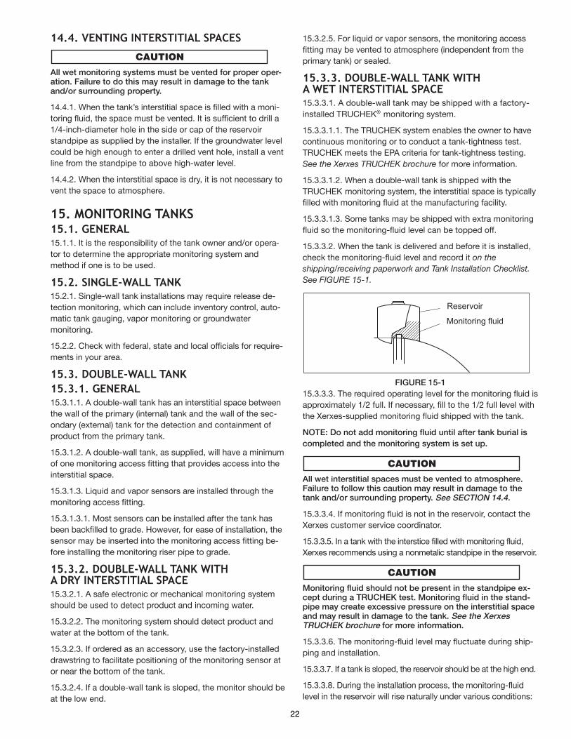
14.4. VentIng InterstItIal spaCes
All wet monitoring systems must be vented for proper oper-ation. Failure to do this may result in damage to the tankand/or surrounding property.
14.4.1. When the tank’s interstitial space is filled with a moni-
toring fluid, the space must be vented. It is sufficient to drill a
1/4-inch-diameter hole in the side or cap of the reservoir
standpipe as supplied by the installer. If the groundwater level
could be high enough to enter a drilled vent hole, install a vent
line from the standpipe to above high-water level.
14.4.2. When the interstitial space is dry, it is not necessary to
vent the space to atmosphere.
15. MonItorIng tanKs 15.1. general15.1.1. It is the responsibility of the tank owner and/or opera-
tor to determine the appropriate monitoring system and
method if one is to be used.
15.2. sIngle-Wall tanK15.2.1. Single-wall tank installations may require release de-
tection monitoring, which can include inventory control, auto-
matic tank gauging, vapor monitoring or groundwater
monitoring.
15.2.2. Check with federal, state and local officials for re quire-
ments in your area.
15.3. douBle-Wall tanK
15.3.1. general15.3.1.1. A double-wall tank has an interstitial space between
the wall of the primary (internal) tank and the wall of the sec-
ondary (external) tank for the detection and containment of
product from the primary tank.
15.3.1.2. A double-wall tank, as supplied, will have a minimum
of one monitoring access fitting that provides access into the
interstitial space.
15.3.1.3. Liquid and vapor sensors are installed through the
monitoring access fitting.
15.3.1.3.1. Most sensors can be installed after the tank has
been backfilled to grade. However, for ease of installation, the
sensor may be inserted into the monitoring access fitting be-
fore installing the monitoring riser pipe to grade.
15.3.2. douBle-Wall tanK WItHa drY InterstItIal spaCe15.3.2.1. A safe electronic or mechanical monitoring system
should be used to detect product and incoming water.
15.3.2.2. The monitoring system should detect product and
water at the bottom of the tank.
15.3.2.3. If ordered as an accessory, use the factory-installed
drawstring to facilitate positioning of the monitoring sensor at
or near the bottom of the tank.
15.3.2.4. If a double-wall tank is sloped, the monitor should be
at the low end.
15.3.2.5. For liquid or vapor sensors, the monitoring access
fitting may be vented to atmosphere (independent from the
primary tank) or sealed.
15.3.3. douBle-Wall tanK WItHa Wet InterstItIal spaCe15.3.3.1. A double-wall tank may be shipped with a factory-
installed TRUCHEK® monitoring system.
15.3.3.1.1. The TRUCHEK system enables the owner to have
continuous monitoring or to conduct a tank-tightness test.
TRUCHEK meets the EPA criteria for tank-tightness testing.
See the Xerxes TRUCHEK brochure for more information.
15.3.3.1.2. When a double-wall tank is shipped with the
TRUCHEK monitoring system, the interstitial space is typically
filled with monitoring fluid at the manufacturing facility.
15.3.3.1.3. Some tanks may be shipped with extra monitoring
fluid so the monitoring-fluid level can be topped off.
15.3.3.2. When the tank is delivered and before it is installed,
check the monitoring-fluid level and record it on the
shipping/receiving paperwork and Tank Installation Checklist.
See FIGURE 15-1.
FIGuRE 15-1
15.3.3.3. The required operating level for the monitoring fluid is
approximately 1/2 full. If necessary, fill to the 1/2 full level with
the Xerxes-supplied monitoring fluid shipped with the tank.
NOTE: Do not add monitoring fluid until after tank burial is
completed and the monitoring system is set up.
All wet interstitial spaces must be vented to atmosphere.Failure to follow this caution may result in damage to thetank and/or surrounding property. See SECTION 14.4.
15.3.3.4. If monitoring fluid is not in the reservoir, contact the
Xerxes customer service coordinator.
15.3.3.5. In a tank with the interstice filled with monitoring fluid,
Xerxes recommends using a nonmetalic standpipe in the reservoir.
Monitoring fluid should not be present in the standpipe ex-cept during a TRuCHEK test. Monitoring fluid in the stand-pipe may create excessive pressure on the interstitial spaceand may result in damage to the tank. See the XerxesTRuCHEK brochure for more information.
15.3.3.6. The monitoring-fluid level may fluctuate during ship-
ping and installation.
15.3.3.7. If a tank is sloped, the reservoir should be at the high end.
15.3.3.8. During the installation process, the monitoring-fluid
level in the reservoir will rise naturally under various conditions:
Reservoir
Monitoring fluid
22
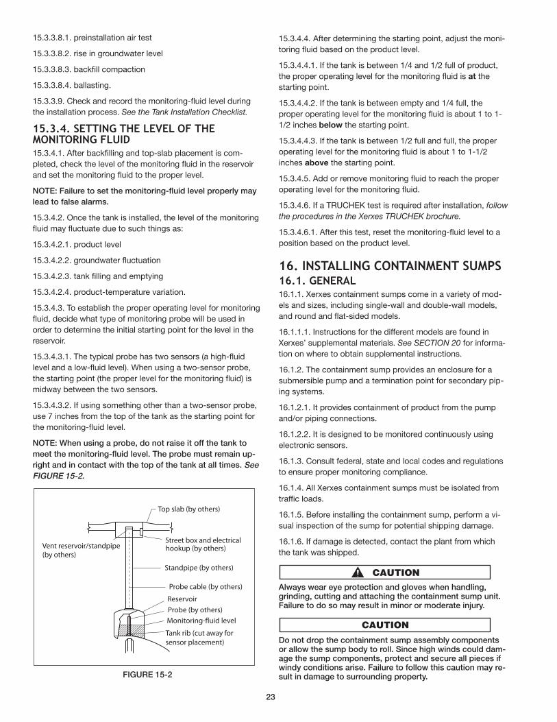
15.3.3.8.1. preinstallation air test
15.3.3.8.2. rise in groundwater level
15.3.3.8.3. backfill compaction
15.3.3.8.4. ballasting.
15.3.3.9. Check and record the monitoring-fluid level during
the installation process. See the Tank Installation Checklist.
15.3.4. settIng tHe leVel oF tHeMonItorIng FluId15.3.4.1. After backfilling and top-slab placement is com-
pleted, check the level of the monitoring fluid in the reservoir
and set the monitoring fluid to the proper level.
NOTE: Failure to set the monitoring-fluid level properly may
lead to false alarms.
15.3.4.2. Once the tank is installed, the level of the monitoring
fluid may fluctuate due to such things as:
15.3.4.2.1. product level
15.3.4.2.2. groundwater fluctuation
15.3.4.2.3. tank filling and emptying
15.3.4.2.4. product-temperature variation.
15.3.4.3. To establish the proper operating level for monitoring
fluid, decide what type of monitoring probe will be used in
order to determine the initial starting point for the level in the
reservoir.
15.3.4.3.1. The typical probe has two sensors (a high-fluid
level and a low-fluid level). When using a two-sensor probe,
the starting point (the proper level for the monitoring fluid) is
midway between the two sensors.
15.3.4.3.2. If using something other than a two-sensor probe,
use 7 inches from the top of the tank as the starting point for
the monitoring-fluid level.
NOTE: When using a probe, do not raise it off the tank to
meet the monitoring-fluid level. The probe must remain up-
right and in contact with the top of the tank at all times. See
FIGuRE 15-2.
FIGuRE 15-2
15.3.4.4. After determining the starting point, adjust the moni-
toring fluid based on the product level.
15.3.4.4.1. If the tank is between 1/4 and 1/2 full of product,
the proper operating level for the monitoring fluid is at the
starting point.
15.3.4.4.2. If the tank is between empty and 1/4 full, the
proper operating level for the monitoring fluid is about 1 to 1-
1/2 inches below the starting point.
15.3.4.4.3. If the tank is between 1/2 full and full, the proper
operating level for the monitoring fluid is about 1 to 1-1/2
inches above the starting point.
15.3.4.5. Add or remove monitoring fluid to reach the proper
operating level for the monitoring fluid.
15.3.4.6. If a TRUCHEK test is required after installation, follow
the procedures in the Xerxes TRUCHEK brochure.
15.3.4.6.1. After this test, reset the monitoring-fluid level to a
position based on the product level.
16. InstallIng ContaInMent suMps16.1. general 16.1.1. Xerxes containment sumps come in a variety of mod-
els and sizes, including single-wall and double-wall models,
and round and flat-sided models.
16.1.1.1. Instructions for the different models are found in
Xerxes’ supplemental materials. See SECTION 20 for informa-
tion on where to obtain supplemental instructions.
16.1.2. The containment sump provides an enclosure for a
submersible pump and a termination point for secondary pip-
ing systems.
16.1.2.1. It provides containment of product from the pump
and/or piping connections.
16.1.2.2. It is designed to be monitored continuously using
electronic sensors.
16.1.3. Consult federal, state and local codes and regulations
to ensure proper monitoring compliance.
16.1.4. All Xerxes containment sumps must be isolated from
traffic loads.
16.1.5. Before installing the containment sump, perform a vi-
sual inspection of the sump for potential shipping damage.
16.1.6. If damage is detected, contact the plant from which
the tank was shipped.
Always wear eye protection and gloves when handling,grinding, cutting and attaching the containment sump unit.Failure to do so may result in minor or moderate injury.
Do not drop the containment sump assembly componentsor allow the sump body to roll. Since high winds could dam-age the sump components, protect and secure all pieces ifwindy conditions arise. Failure to follow this caution may re-sult in damage to surrounding property.
Vent reservoir/standpipe (by others)
Top slab (by others)
Street box and electricalhookup (by others)
Standpipe (by others)
Probe cable (by others)
Reservoir
Probe (by others)
Monitoring-fluid level
Tank rib (cut away for sensor placement)
23
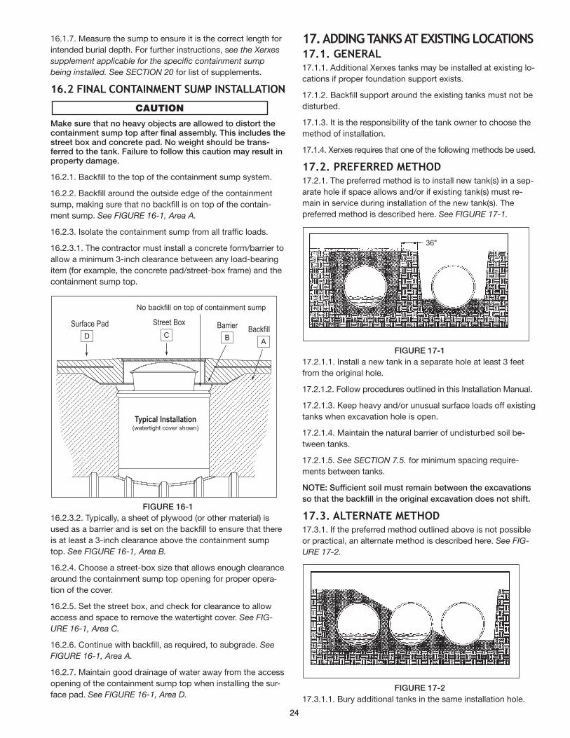
16.1.7. Measure the sump to ensure it is the correct length for
intended burial depth. For further instructions, see the Xerxes
supplement applicable for the specific containment sump
being installed. See SECTION 20 for list of supplements.
16.2 FInal ContaInMent suMp InstallatIon
Make sure that no heavy objects are allowed to distort thecontainment sump top after final assembly. This includes thestreet box and concrete pad. No weight should be trans-ferred to the tank. Failure to follow this caution may result inproperty damage.
16.2.1. Backfill to the top of the containment sump system.
16.2.2. Backfill around the outside edge of the containment
sump, making sure that no backfill is on top of the contain-
ment sump. See FIGURE 16-1, Area A.
16.2.3. Isolate the containment sump from all traffic loads.
16.2.3.1. The contractor must install a concrete form/barrier to
allow a minimum 3-inch clearance between any load-bearing
item (for example, the concrete pad/street-box frame) and the
containment sump top.
FIGuRE 16-1
16.2.3.2. Typically, a sheet of plywood (or other material) is
used as a barrier and is set on the backfill to ensure that there
is at least a 3-inch clearance above the containment sump
top. See FIGURE 16-1, Area B.
16.2.4. Choose a street-box size that allows enough clearance
around the containment sump top opening for proper opera-
tion of the cover.
16.2.5. Set the street box, and check for clearance to allow
access and space to remove the watertight cover. See FIG-
URE 16-1, Area C.
16.2.6. Continue with backfill, as required, to subgrade. See
FIGURE 16-1, Area A.
16.2.7. Maintain good drainage of water away from the access
opening of the containment sump top when installing the sur-
face pad. See FIGURE 16-1, Area D.
17. addIng tanKs at eXIstIng loCatIons17.1. general 17.1.1. Additional Xerxes tanks may be installed at existing lo-
cations if proper foundation support exists.
17.1.2. Backfill support around the existing tanks must not be
disturbed.
17.1.3. It is the responsibility of the tank owner to choose the
method of installation.
17.1.4. Xerxes requires that one of the following methods be used.
17.2. preFerred MetHod17.2.1. The preferred method is to install new tank(s) in a sep-
arate hole if space allows and/or if existing tank(s) must re-
main in service during installation of the new tank(s). The
preferred method is described here. See FIGURE 17-1.
FIGuRE 17-1
17.2.1.1. Install a new tank in a separate hole at least 3 feet
from the original hole.
17.2.1.2. Follow procedures outlined in this Installation Manual.
17.2.1.3. Keep heavy and/or unusual surface loads off existing
tanks when excavation hole is open.
17.2.1.4. Maintain the natural barrier of undisturbed soil be-
tween tanks.
17.2.1.5. See SECTION 7.5. for minimum spacing require-
ments between tanks.
NOTE: Sufficient soil must remain between the excavations
so that the backfill in the original excavation does not shift.
17.3. alternate MetHod17.3.1. If the preferred method outlined above is not possible
or practical, an alternate method is described here. See FIG-
URE 17-2.
FIGuRE 17-2
17.3.1.1. Bury additional tanks in the same installation hole.
BackfillSurface Pad Street Box Barrier
No backfill on top of containment sump
Typical Installation(watertight cover shown)
D C B A
36"
24
17.3.1.2. Empty existing tanks to less than one-quarter (1/4) of
capacity.
17.3.1.3. Remove the surface slab.
17.3.1.4. Enlarge the excavation for the new tanks, but leave
as much backfill as possible around the existing tanks.
17.3.1.5. Install shoring, if necessary, to make sure that exist-
ing tanks do not move and that sufficient backfill remains
around them.
Failure to shore tanks if necessary to keep the existingtank(s) from moving could result in death or serious injury.
17.3.1.6. Follow the procedures and requirements for installing
the tanks as outlined in this Installation Manual.
17.3.1.7. See SECTION 6 for backfill requirements, and
SECTION 7 for excavation and spacing requirements.
If any existing tank(s) should move during the installation ofnew tanks, they must be removed and reinstalled accordingto tank manufacturer’s instructions. Failure to follow thiscaution may result in minor or moderate injury.
18. operatIng guIdelInes18.1. general 18.1.1. Owner must retain the Installation Manual and Op er at-
ing Guidelines for future reference to operating guidelines.
18.1.2. In addition to these installation instructions and operat-
ing guidelines, follow all federal, state and local laws, regula-
tions, codes and safety precautions that pertain to
underground storage tanks and/or their associated systems.
18.1.3. Consult supplemental materials (see SECTION 20),
tank brochures, separate product instructions (such as
oil/water separators) and separate accessory instructions,
which are available upon request from the Xerxes customer
service coordinator. Most of these documents are also avail-
able at www.xerxes.com.
18.1.4. Consult the applicable limited warranty for further op-
erating guidelines and limitations. A copy of the applicable
Xerxes limited warranty is found in the printed material that
accompanies each tank, in each applicable product brochure
and at www.xerxes.com. It is also available upon request from
the Xerxes customer service coordinator.
18.2. teMperature lIMIts For storedproduCts and MaterIals18.2.1. Each Xerxes tank is designed to store materials identi-
fied in the manufacturer’s applicable limited warranty.
Products and materials must be stored in the tank appropri-ate for the specific product or material. Failure to follow thiscaution may result in damage to the tank and/or surroundingproperty.
Storing products and materials other than those identified inthe manufacturer's applicable limited warranty will voidXerxes’ obligations under the limited warranty and may re-sult in tank failure and/or damage to surrounding property.
18.2.2. All products and materials must be stored at ambient
temperature except as follows:
18.2.2.1. The maximum temperature for storing fuel oils is 150°F.
18.2.2.2. The maximum temperature for storing nonpotable
water is 150° F.
NOTE: Potable water is to be stored at ambient temperature.
18.2.2.3. The maximum temperature for storing wastewater
products and materials is 150°F.
18.2.2.4. The maximum temperature for storing chemicals is 100°F.
Introducing or storing a product or material into a tank inexcess of the allowable temperature may damage the tank.Failure to follow this caution may result in damage to thetank and/or surrounding property.
18.3. enterIng tanKs18.3.1. Do not allow anyone to enter the tank unless it has been
properly emptied and vented, and unless the person entering
the tank has been trained in confined-space entry procedures
and applicable OSHA regulations.
Improper tank entry could cause fire, explosion or as phyx i a tion,and could result in death or serious injury.
18.4. FIllIng tanKs (In general)18.4.1. Never overfill the tank.
18.4.2. If pump- or pressure-filling a tank, owner/operator
must take precautions to prevent overpressurization.
Overpressurizing the tank could result in tank failure, andcould result in death or serious injury.
If a tank does not have overfill protection, the vent must beunrestricted and the vent size must be equal to or greaterthan the fill. Failure to follow this warning could result indeath or serious injury.
18.5 FIllIng ul-laBeled tanKs
Xerxes does not recommend pump- or pressure-filling of thetank because an overfill or overpressurization could occur.Over fill ing the tank while under pressure could cause tankfailure even if the tank is vented properly. Failure to followthis warning could result in tank failure, and could result indeath or serious injury.
18.5.1. Each time the tank is filled, the owner/operator must
make sure the tank is properly vented. See SECTION 14.
25
18.5.2. Owner/operator must determine whether the tank has
overfill protection, such as an automatic shut-off device (flap-
per valve) or vent-restriction device (ball-float valve), which will
close off the internal piping and reduce the tank’s capacity.
18.5.3. If a tank has a vent-restriction device (ball-float valve),
Xerxes recommends that the tank be gravity-filled only.
18.5.4. Owner/operator must notify whoever fills the tank if the
tank has overfill protection, which reduces the tank’s capacity.
18.5.5. Before each tank filling, owner/operator or the delivery
service must determine the tank’s reduced capacity due to the
overfill protection, then consult the instructions or guidelines
provided by the installer and manufacturer of the overfill-pro-
tection device to determine how much additional product the
tank can hold.
18.5.6. Owner/operator must ensure that the fill line and drop
tube are adequately grounded to prevent static discharge dur-
ing filling.
18.5.7. Initial fill rate should be controlled to limit the possibil-
ity of product sloshing.
19. lIMIted WarrantIes19.1. general 19.1.1. Each product is covered by a product-specific limited
warranty, which contains operating guidelines and parameters
that should be reviewed as applicable. A copy of the applica-
ble Xerxes limited warranty is found in the printed material that
accompanies each tank, in applicable product brochures and
at www.xerxes.com. It is also available upon request from the
Xerxes customer service coordinator.
20. suppleMental MaterIals20.1. general20.1.1. Supplemental materials, which may apply to specific
instal la tions and/or conditions, are available upon request
from the Xerxes customer service coordinator or from techni-
cal support at Xerxes Minneapolis, MN. Most supplemental
materials are also available at www.xerxes.com.
20.1.1.1. Among those materials available from the Xerxes
customer service coordinator and at www.xerxes.com are the
following:
• Diesel Exhaust Fluid (DEF) Tank Installation Instructions
• Double-Wall Containment Sump Installation Instructions
• Field Fiberglass Lay-Up Instructions for Containment Sumps
• Flat-Bottom Containment Sump Installation Instructions
• Flexible Dipstick Monitoring Instructions
• Large Bottom Sump Installation Instructions
• Man-Out-of-Hole (MOH) Strap Instructions
• New York City Double-Wall Tank Installation/Testing Supplement
• Prefabricated Deadmen Installation Instructions
• Preinstallation Testing Instructions for Water/Wastewater
Tanks Factory-Equipped for Pressure Testing
• Primary Backfill Requirements
• TRUCHEK® Brochure
• Single-Wall Containment Sump Installation Instructions
for Flat-Sided Containment Sumps
• Single-Wall Containment Sump Installation Instructions
for Round-Sided Containment Sumps
• Split Backfill Instructions
• Triple-Wall Tank Preinstallation Testing Instructions
• Two-Part Sealant Mixing/Handling Instructions
• Watertight Cover Gasket Replacement Instructions
• Wet Well Installation Instructions and Operating Guidelines.
20.1.1.2. Among those materials available from technical sup-
port at Xerxes Minneapolis, MN, are the following:
• Alternate Backfill (Sand) Installation Instructions
• Cast-in-Place Deadmen Installation
• Deep Burial Installation Guidelines.
21. retentIon oF InstallatIon Manual21.1. general21.1.1. After installation, tank installer must give the Installa-
tion Manual and the completed Tank Installation Checklist to
the tank owner.
21.1.2. After installation, tank owner must retain the In stal la tion
Manual for future reference to operating guidelines. Tank owner
must also retain a copy of the Tank Installation Checklist.
26
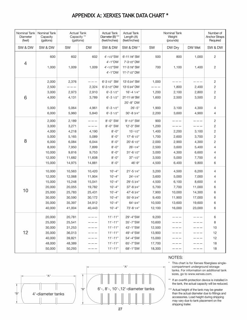
"A"
"B"
"A"
"B"
NOTES:
* This chart is for Xerxes fiberglass single-compartment underground storage tanks. For information on additional tank sizes, go to www.xerxes.com.
** If an overfill-protection device is installed in the tank, the actual capacity will be reduced.
*** Actual height of the tank may be greater than the actual diameter due to fittings and accessories. Load height during shipping may vary due to tank placement on the shipping trailer.
6'-, 8'-, 10'-,12'-diameter tanks
4'-diameter tanks
appendIX a: XerXes tanK data CHart *
4
600
1,000
602
1,009
602
1,009
4'-1/2"SW
4'-1"DW
4'-1/2"SW
4'-1"DW
6'-11 7/8" SW
7'-3 1/2" DW
11'-3 7/8" SW
11'-7 1/2" DW
500
700
800
1,100
1,000
1,400
2
2
6
2,000
2,500
3,000
4,000
5,000
6,000
2,376
———
2,973
4,131
5,064
5,960
———
2,324
2,910
3,789
4,961
5,840
6'-3 1/2" SW
6'-3 1/2" DW
6'-3 1/2"
6'-3 1/2"
6'-3 1/2"
6'-3 1/2"
13'-5 3/4" SW
13'-5 3/4" DW
16'-4 1/4"
21'-11 1/8"SW
20'-8" DW
26'-5"
30'-8 3/4"
1,000
———
1,200
1,600
1,900
2,200
———
1,800
2,100
2,500
3,100
3,600
———
2,400
2,800
3,500
4,300
4,900
2
2
2
2
4
4
8
2,000
3,000
4,000
5,000
6,000
8,000
10,000
12,000
15,000
2,189
3,271
4,218
5,165
6,084
7,950
9,816
11,682
14,975
———
———
4,190
5,089
6,044
7,899
9,753
11,608
14,881
8'-0" SW
8'-0" SW
8'-0"
8'-0"
8'-0"
8'-0"
8'-0"
8'-0"
8'-0"
9'-1/2" SW
12'-3" SW
15'-1/2"
17'-8 1/2"
20'-6 1/2"
26'-1/4"
31'-6 1/2"
37'-1/2"
46'-9"
900
1,200
1,400
1,700
2,000
2,500
3,000
3,500
4,500
———
———
2,200
2,600
2,900
3,600
4,300
5,000
6,400
———
———
3,100
3,700
4,300
5,400
6,600
7,700
9,800
2
2
2
2
2
4
4
4
6
10
10,000
12,000
15,000
20,000
25,000
30,000
35,000
40,000
10,563
12,068
15,248
20,055
25,783
30,590
35,397
41,004
10,420
11,904
15,041
19,782
25,431
30,172
34,912
40,443
10'-4"
10'-4"
10'-4"
10'-4"
10'-4"
10'-4"
10'-4"
10'-4"
21'-5 1/4"
24'-1/4"
29'-5 3/4"
37'-8 3/4"
47'-6 3/4"
55'-9 3/4"
64'-3/4"
73'-8 1/4"
3,200
3,600
4,500
5,700
7,900
9,400
10,500
12,100
4,500
5,000
6,100
7,700
10,000
11,900
13,600
16,000
6,200
7,000
8,600
11,000
14,300
17,000
19,600
23,000
4
4
4
6
6
6
6
6
12
20,000
25,000
30,000
35,000
40,000
48,000
50,000
20,781
25,541
31,253
36,013
39,821
48,389
50,293
———
———
———
———
———
———
———
11'-11"
11'-11"
11'-11"
11'-11"
11'-11"
11'-11"
11'-11"
29'-4"SW
35'-7"SW
43'-1"SW
49'-4"SW
54'-4"SW
65'-7"SW
68'-1"SW
9,200
10,600
12,500
13,900
15,000
17,700
18,300
———
———
———
———
———
———
———
———
———
———
———
———
———
———
6
8
10
12
12
18
18
Nominal TankDiameter
(feet)
Nominal TankCapacity (gallons)
Actual Tank Diameter (B) ***(feet/inches)
Actual Tank Length (A)
(feet/inches)
Number ofAnchor Straps
Required
SW & DW SW & DW SW DW SW & DW SW & DW * SW DW Dry DW Wet SW & DW
27
Actual TankCapacity **
(gallons)
Nominal Tank Weight
(pounds)
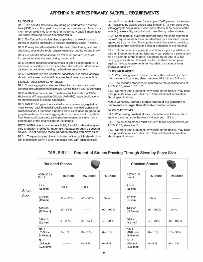
ASTM C 33Siz e # #6 Stone #67 Stone #7 Stone
1 inch
[25 mm] 100 % 100 % ———
3/4 inch
[19 mm]90—100 % 90—100 % 100 %
1/2 inch
[12.5 mm]20—55 % ——— 90—100 %
3/8 inch
[9.5 mm]0—15 % 20—55 % 40—70 %
No. 4
.0187 inch
[4.75 mm]
0—5 % 0—10 % 0—15 %
No. 8
.094 inch
[2.36 mm]
——— 0—5 % 0—5 %
Rounded Stones
ASTM C 33Size # #7 Stone #8 Stone
1 inch
[25 mm] ——— ———
3/4 inch
[19 mm]100 % ———
1/2 inch
[12.5 mm]90—100 % 100 %
3/8 inch
[9.5 mm]40—70 % 85—100 %
No. 4
.0187 inch
[4.75 mm]
0—15 % 10—30 %
No. 8
.094 inch
[2.36 mm]
0—5 % 0—10 %
Crushed Stones
28
appendIX B: XerXes prIMarY BaCKFIll reQuIreMents
B1. general
B1.1. The backfill material surrounding an underground storagetank (UST) is a critical part of a proper tank installation. This docu-ment gives guidelines for choosing the primary backfill material touse when installing Xerxes fiberglass tanks.
B1.2. The Xerxes Installation Manual specifies that select roundedstones or crushed stones are to be used as primary backfill material.
B1.3. Primary backfill material is to be clean, free-flowing, and free ofdirt, sand, large rocks, roots, organic materials, debris, ice and snow.
B1.4. No backfill material shall be frozen or contain lumps offrozen material at any time during placement.
B1.5. Another important characteristic of good backfill material ishardness or stability when exposed to water or loads. Most materi-als have no problems meeting the hardness requirement.
B1.5.1. Materials like soft limestone, sandstone, sea shells or shaleshould not be used as backfill because they break down over time.
B2. aCCeptaBle BaCKFIll MaterIals
B2.1. Coarse aggregate is a technical term for the material (roundedstones and crushed stones) that meets Xerxes' backfill size requirements.
B2.2. ASTM International and The American Association of StateHighway and Transportation Officials (AASHTO) have specificationsfor standard sizes of coarse aggregate.
B2.3. TABLE B1-1 gives the standard sizes of coarse aggregate thatmeet Xerxes' backfill material specifications for rounded stones andcrushed stones. It identifies standard sieve sizes used to grade ag-gregate material. For each aggregate size, the amount of materialfiner than each laboratory sieve (square openings) is given as apercentage of the total weight of the sample.
NOTE: ASTM uses size numbers 6, 67, 7 and 8 to describe spe-cific gradation profiles for materials that pass through a series ofsieves. Do not confuse these gradation profiles with sieve sizes.
B2.3.1. The percentages give an indication of the particle size distribu-tion or gradation within a given aggregate size. With aggregate size
number 6 of rounded stones, for example, 20–55 percent of the sam-ple (measured by weight) should pass through a 1/2-inch sieve. And,with aggregate size number 7 of crushed stones, 0–15 percent of thesample (measured by weight) should pass through a No. 4 sieve.
B2.4. Some material suppliers may produce materials that meetXerxes' requirements but are not identified by a standard coarseaggregate size number. The supplier should be able to provide aspecification that identifies the size or gradation of the material.
B2.4.1. If the material supplier is unable to supply a gradation re-port, an independent testing laboratory can perform a sieve analy-sis on a sample of the material according to the ASTM C 136testing specifications. The test results can then be comparedagainst the size requirements for rounded or crushed stonesshown in table B1-1.
B3. rounded stones
B3.1. When using select rounded stones, the material is to be amix of rounded particles, sizes between 1/8 inch and 3/4 inch.
B3.2. The rounded stones must conform to the specifications ofASTM C 33, sizes 6, 67 or 7.
B3.3. No more than 5 percent (by weight) of the backfill may passthrough a #8 sieve. See TABLE B1-1 for additional informationabout specifications.
NOTE: Generally, rounded stones that meet the gradation re-quirements are larger than allowable crushed stones.
B4. CrusHed stones
B4.1. When using crushed stones, the material is to be a mix ofangular particles, sizes between 1/8 inch and 1/2 inch.
B4.2. The crushed stones must conform to the specifications ofASTM C 33, sizes 7 or 8.
B4.3. No more than 5 percent (by weight) of the backfill may passthrough a #8 sieve. See TABLE B1-1 for additional informationabout specifications.
TABLE B1-1—Percent of Stones Passing Through Sieve by Sieve Size
Sieve
Size
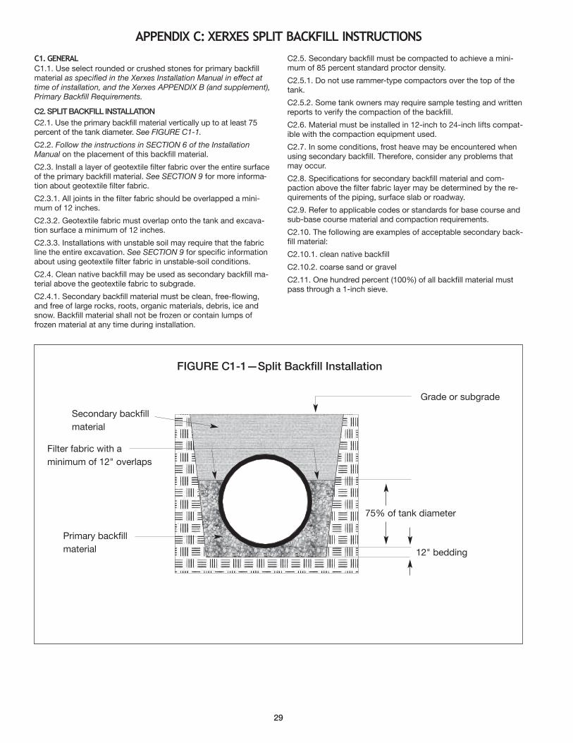
29
appendIX C: XerXes splIt BaCKFIll InstruCtIons
C1. general
C1.1. Use select rounded or crushed stones for primary backfillmaterial as specified in the Xerxes Installation Manual in effect attime of installation, and the Xerxes APPENDIX B (and supplement),Primary Backfill Requirements.
C2. SPLIT BACKFILL INSTALLATION
C2.1. Use the primary backfill material vertically up to at least 75percent of the tank diameter. See FIGURE C1-1.
C2.2. Follow the instructions in SECTION 6 of the InstallationManual on the placement of this backfill material.
C2.3. Install a layer of geotextile filter fabric over the entire surfaceof the primary backfill material. See SECTION 9 for more informa-tion about geotextile filter fabric.
C2.3.1. All joints in the filter fabric should be overlapped a mini-mum of 12 inches.
C2.3.2. Geotextile fabric must overlap onto the tank and excava-tion surface a minimum of 12 inches.
C2.3.3. Installations with unstable soil may require that the fabricline the entire excavation. See SECTION 9 for specific informationabout using geotextile filter fabric in unstable-soil conditions.
C2.4. Clean native backfill may be used as secondary backfill ma-terial above the geotextile fabric to subgrade.
C2.4.1. Secondary backfill material must be clean, free-flowing,and free of large rocks, roots, organic materials, debris, ice andsnow. Backfill material shall not be frozen or contain lumps offrozen material at any time during installation.
C2.5. Secondary backfill must be compacted to achieve a mini-mum of 85 percent standard proctor density.
C2.5.1. Do not use rammer-type compactors over the top of thetank.
C2.5.2. Some tank owners may require sample testing and writtenreports to verify the compaction of the backfill.
C2.6. Material must be installed in 12-inch to 24-inch lifts compat-ible with the compaction equipment used.
C2.7. In some conditions, frost heave may be encountered whenusing secondary backfill. Therefore, consider any problems thatmay occur.
C2.8. Specifications for secondary backfill material and com-paction above the filter fabric layer may be determined by the re-quirements of the piping, surface slab or roadway.
C2.9. Refer to applicable codes or standards for base course andsub-base course material and compaction requirements.
C2.10. The following are examples of acceptable secondary back-fill material:
C2.10.1. clean native backfill
C2.10.2. coarse sand or gravel
C2.11. One hundred percent (100%) of all backfill material mustpass through a 1-inch sieve.
FIGuRE C1-1—Split Backfill Installation
Grade or subgrade
75% of tank diameter
12" bedding
Filter fabric with a
minimum of 12" overlaps
Secondary backfill
material
Primary backfill
material
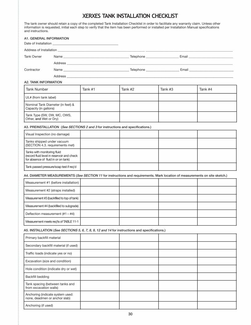
The tank owner should retain a copy of the completed Tank Installation Checklist in order to facilitate any warranty claim. Unless otherinformation is requested, initial each step to verify that the item has been performed or installed per Installation Manual specificationsand instructions.
XerXes tanK InstallatIon CHeCKlIst
30
A1. GENERAL INFORMATION
Date of Installation ________________________________________
Address of Installation _____________________________________________________ _____________________________________________________
Tank Owner Name ________________________________________ Telephone ____________________ Email ___________________________
Address _____________________________________________________________________________________________________
Contractor Name ________________________________________ Telephone __________________ Email ___________________________
Address __________________________________________________________________________________________
A2. TANK INFORMATION
A3. PREINSTALLATION (See SECTIONS 2 and 3 for instructions and specifications.)
A4. DIAMETER MEASuREMENTS (See SECTION 11 for instructions and requirements. Mark location of measurements on site sketch.)
UL# (from tank label)
Nominal Tank Diameter (in feet) & Capacity (in gallons)
Tank Type (SW, DW, MC, OWS, Other, and Wet or Dry)
Measurement #1 (before installation)
Measurement #2 (straps installed)
Measurement #3 (backfilled to top of tank)
Measurement #4 (backfilled to subgrade)
Deflection measurement (#1—#4)
Measurement meets req’ts of TABLE 11-1
Visual Inspection (no damage)
Tanks shipped under vacuum(SECTION 4.3. requirements met)
Tanks with monitoring fluid (record fluid level in reservoir and checkfor absence of fluid in or on tank)
Tank passed pressure/soap test if req'd
Primary backfill material
Secondary backfill material (if used)
Traffic loads (indicate yes or no)
Excavation (size and condition)
Hole condition (indicate dry or wet)
Backfill bedding
Tank spacing (between tanks andfrom excavation walls)
Anchoring (indicate system used:none, deadmen or anchor slab)
Anchoring (if used)
Tank Number Tank #1 Tank #2 Tank #3 Tank #4
A5. INSTALLATION (See SECTIONS 5, 6, 7, 8, 9, 12 and 14 for instructions and specifications.)
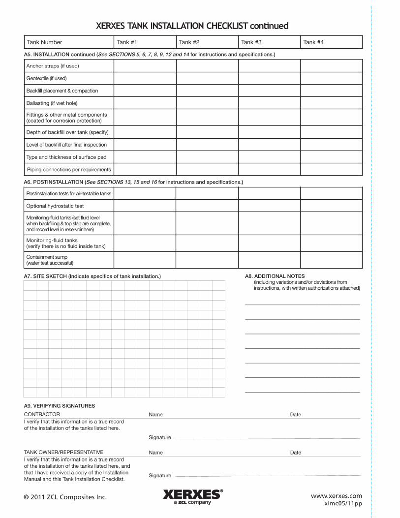
A9. VERIFYING SIGNATuRES
CONTRACTOR
I verify that this information is a true record
of the installation of the tanks listed here.
TANK OWNER/REPRESENTATIVE
I verify that this information is a true record
of the installation of the tanks listed here, and
that I have received a copy of the Installation
Manual and this Tank Installation Checklist.
Name Date
Signature
Anchor straps (if used)
Geotextile (if used)
Backfill placement & compaction
Ballasting (if wet hole)
Fittings & other metal components(coated for corrosion protection)
Depth of backfill over tank (specify)
Level of backfill after final inspection
Type and thickness of surface pad
Piping connections per requirements
Tank Number Tank #1 Tank #2 Tank #3 Tank #4
A5. INSTALLATION continued (See SECTIONS 5, 6, 7, 8, 9, 12 and 14 for instructions and specifications.)
A8. ADDITIONAL NOTES(including variations and/or deviations from instructions, with written authorizations attached)
_______________________________________
_______________________________________
_______________________________________
_______________________________________
_______________________________________
_______________________________________
_______________________________________
A7. SITE SKETCH (Indicate specifics of tank installation.)
Postinstallation tests for air-testable tanks
Optional hydrostatic test
Monitoring-fluid tanks (set fluid levelwhen backfilling & top slab are complete,and record level in reservoir here)
Monitoring-fluid tanks (verify there is no fluid inside tank)
Containment sump (water test successful)
A6. POSTINSTALLATION (See SECTIONS 13, 15 and 16 for instructions and specifications.)
XerXes tanK InstallatIon CHeCKlIst continued
Name Date
Signature
www.xerxes.comximc05/11pp
© 2011 ZCL Composites Inc.

7901 Xerxes Avenue South | Minneapolis | MN | 55431-1288
Ph: 952.887.1890 Fax: 952.887.1882 www.xerxes.com
Drummondville, QCDrummondville, QC
Edmonton, AB
ximc05/11pp© 2011 ZCL Composites Inc.
Xerxes Manufacturing Facilities
Anaheim, CAPhone 714.630.0012Fax 714.632.7133
Hagerstown, MDPhone 301.223.6933Fax 301.223.6836
Seguin, TXPhone 830.372.0090Fax 830.372.0321
Tipton, IAPhone 563.886.6172Fax 563.886.2042
ZCL Manufacturing Facilities
Edmonton, ABPhone 800.661.8265Fax 780.466.6126
Drummondville, QCPhone 800.661.8265Fax 780.466.6126
Hagerstown, MD