Embed Size (px)
Citation preview
Industrial DC/DC CONVERTERMGDI-10 Standard Input : 10W POWER
• Low profile : 0,33 “ ( 8.5mm)
• Nominal power of 10 W without derating
• Wide temperature range : -40°C/+95°C case
• High efficiency up to 83 %
• Soft start
• Galvanic isolation 1.500 VDC
• Integrated LC EMI filter
• Permanent short circuit protection
• No optocoupler for high reliability
• RoHS process
Gaia Converter FC97-006.01/16 Revision P©
REDEFINING THE SOURCE OF POWER
1-General
IndustrialGrade
For locations, phone, fax, E-Mail see back cover
2-Product Selection
Input Voltage Range
B : 3.3 VDCC : 5 VDC or +/-5VDCE : 12 VDC or +/-12VDCF : 15 VDC or +/-15VDC
Permanent
C : 4,5-5,5 VDCI : 18-36 VDC
Output
5
The MGDI-10 series is a full family of DC/DCpower modules designed for use in distributedpower architecture and are particularly suitablefor mobile or ground fixed applications intransportation, industry and télécommunicationareas. These modules use a high frequency fixedswitching technic at 480 KHz providing excellentreliability, low noise characteristics, high powerdensity and a low profile package. Standardmodels are available with nominal input volta-ges as 5, 12, or 24 volts in range of 4,5-5,5 or18-36 volts. The series include single and bioutput voltage choices of 3,3, 5, 12, 15, +/-5,+/-12 or +/-15 volts.No external heatsink is required for the MGDI-10 series to supply 10W output power over thecase temperature range of -40°C up to 95°C.The MGDI-10 series is designed in conformitywith safety standards EN60950 and UL1950.
All the modules are designed with LC networkfilters to minimize reflected input current rippleand output voltage ripple according to EN55022and FCC Part 15J standard.The modules include a soft-start, an inputundervoltage lock-out, a permanent short cir-cuit protection and an output overvoltage pro-tection to ensure efficient module protections.The soft-start allows current limitation andeliminates inrush current during start-up. Theshort circuit protection completely protects themodules against short-circuits of any durationby a shut-down and restores to normal whenthe overload is removed.The design has been carried out with surfacemount components and is manufactured in afully automated process to guarantee highquality. Each module is tested and burned inwith a GAIA Converter automated testequipment.
2:1 Standard InputSingle & Bi Outputs
Metallic case - 1 500 VDC Isolation
Single output model : MGDSI - 10 - input output
Bi output model : MGDBI - 10 - input output
Options :
/M : option for On/Off function
For locations, phone, fax, E-Mail see back cover
2
IndustrialGradeMGDI-10 Standard Input Series
Gaia Converter FC97-006.01/16 Revision P©
5
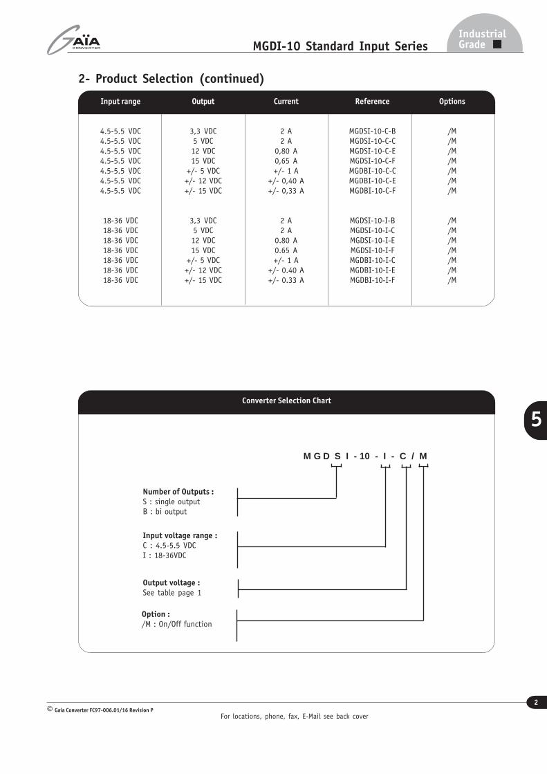
2- Product Selection (continued)
Current
2 A2 A
0,80 A0,65 A+/- 1 A
+/- 0,40 A+/- 0,33 A
2 A2 A
0.80 A0.65 A+/- 1 A
+/- 0.40 A+/- 0.33 A
Reference
MGDSI-10-C-BMGDSI-10-C-CMGDSI-10-C-EMGDSI-10-C-FMGDBI-10-C-CMGDBI-10-C-EMGDBI-10-C-F
MGDSI-10-I-BMGDSI-10-I-CMGDSI-10-I-EMGDSI-10-I-FMGDBI-10-I-CMGDBI-10-I-EMGDBI-10-I-F
Output
3,3 VDC5 VDC12 VDC15 VDC
+/- 5 VDC+/- 12 VDC+/- 15 VDC
3,3 VDC5 VDC12 VDC15 VDC
+/- 5 VDC+/- 12 VDC+/- 15 VDC
Input range
4.5-5.5 VDC4.5-5.5 VDC4.5-5.5 VDC4.5-5.5 VDC4.5-5.5 VDC4.5-5.5 VDC4.5-5.5 VDC
18-36 VDC18-36 VDC18-36 VDC18-36 VDC18-36 VDC18-36 VDC18-36 VDC
Options
/M/M/M/M/M/M/M
/M/M/M/M/M/M/M
Converter Selection Chart
M G D S I - 10 - I - C / M
Number of Outputs :S : single outputB : bi output
Input voltage range :C : 4.5-5.5 VDCI : 18-36VDC
Output voltage :See table page 1
Option :/M : On/Off function

For locations, phone, fax, E-Mail see back cover
3
IndustrialGradeMGDI-10 Standard Input Series
Gaia Converter FC97-006.01/16 Revision P©
5
3- Electrical SpecificationsData are valid at +25°C, unless otherwise specified.
Parameter ConditionsLimit ortypical
UnitsSingle Output MGDSI- 10
10 - C 10 - I
Input
Nominal input voltage Full temperature range Nominal VDC 5 24
Permanent inputvoltage range (Ui)
Full temperature range Min. - Max. VDC 4,5- 5,5 18- 36
Undervoltage lock-out(UVLO)
turn-on/turn-off thresholdMinimumMaximum
VDCVDC
44,5
1617,5
Start up timeUi nominalNominal outputFull load : resistive
Maximum ms 30 30
Reflected ripple currentUi nominal, full load at switching freq. BW =20MHzDecoupling capacitor 10µF
Typical mApp 50 30
Input current in shortcircuit mode (Average)
Ui nominalShort-circuit
Maximum mA 150 30
No load input currentUi nominalNo load
Maximum mA 150 30
Output
Output voltage *Full temperature rangeUi min. to max.75% load
NominalNominalNominalNominal
VDCVDCVDCVDC
3,351215
3,351215
Set Point accuracyAmbient temperature : +25°cUi nominal, 75% load
Maximum % +/- 2 +/- 2
Output powerFull temperature rangeUi min. to max.
Maximum W 10 10
Output current3,3V output5V output12V output15V output
Full temperature rangeUi min. to max.
MaximumMaximumMaximumMaximum
AAAA
22
0,800,65
22
0,800,65
Ripple output voltage **3,3V and 5V output12V output15V output
Ui nominalFull loadBW = 20MHz
MaximumMaximumMaximum
mVppmVppmVpp
50100150
50100150
Line regulationUi min. to max.Full load
Typical % +/- 1,5 +/- 1,5
Load regulation ***Ui nominal25% to full load
Typical % +/- 2,5 +/- 2,5
EfficiencyUi nominalFull load
Typical % 77 83
Maximum admissibleCapacitive load3,3V and 5V output12V and 15V output
Ui nominalFull loadPer output
MaximumMaximum
µFµF
1 000330
1 000330
Note * : For proper operation the MGDI-10 module requires to install a 22µF chemical or tantalum capacitance accross output terminals.Note ** : The ripple output voltage is the periodic AC component imposed on the output voltage, an aperiodic and random component (noise) has also to be considered.
This noise can be reduced by adding an external capacitor (typically 10nF/rated voltage depending on isolation requirement) connected between the pin Gin and thepin Gout of the converter. This capacitor should be layed-out as close as possible from the converter.
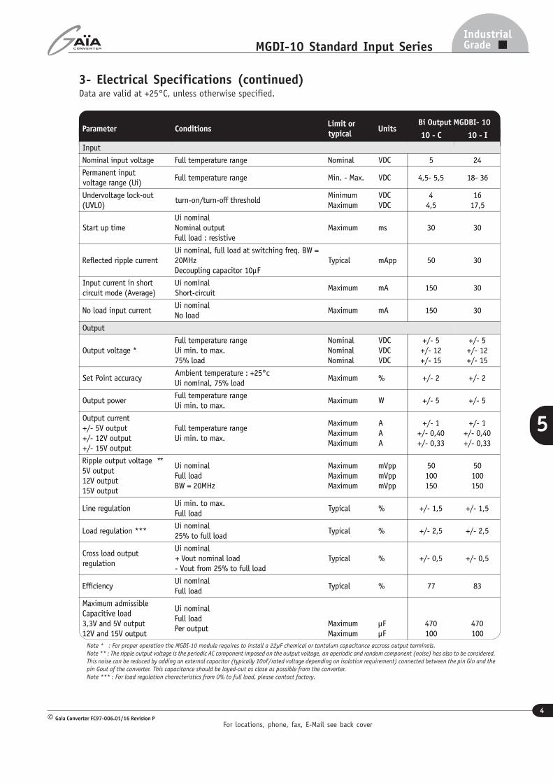
Note *** : For load regulation characteristics from 0% to full load, please contact factory.
For locations, phone, fax, E-Mail see back cover
4
IndustrialGradeMGDI-10 Standard Input Series
Gaia Converter FC97-006.01/16 Revision P©
5
3- Electrical Specifications (continued)Data are valid at +25°C, unless otherwise specified.
Parameter ConditionsLimit ortypical
UnitsBi Output MGDBI- 10
10 - C 10 - I
Input
Nominal input voltage Full temperature range Nominal VDC 5 24
Permanent inputvoltage range (Ui)
Full temperature range Min. - Max. VDC 4,5- 5,5 18- 36
Undervoltage lock-out(UVLO)
turn-on/turn-off thresholdMinimumMaximum
VDCVDC
44,5
1617,5
Start up timeUi nominalNominal outputFull load : resistive
Maximum ms 30 30
Reflected ripple currentUi nominal, full load at switching freq. BW =20MHzDecoupling capacitor 10µF
Typical mApp 50 30
Input current in shortcircuit mode (Average)
Ui nominalShort-circuit
Maximum mA 150 30
No load input currentUi nominalNo load
Maximum mA 150 30
Output
Output voltage *Full temperature rangeUi min. to max.75% load
NominalNominalNominal
VDCVDCVDC
+/- 5+/- 12+/- 15
+/- 5+/- 12+/- 15
Set Point accuracyAmbient temperature : +25°cUi nominal, 75% load
Maximum % +/- 2 +/- 2
Output powerFull temperature rangeUi min. to max.
Maximum W +/- 5 +/- 5
Output current+/- 5V output+/- 12V output+/- 15V output
Full temperature rangeUi min. to max.
MaximumMaximumMaximum
AAA
+/- 1+/- 0,40+/- 0,33
+/- 1+/- 0,40+/- 0,33
Ripple output voltage **5V output12V output15V output
Ui nominalFull loadBW = 20MHz
MaximumMaximumMaximum
mVppmVppmVpp
50100150
50100150
Line regulationUi min. to max.Full load
Typical % +/- 1,5 +/- 1,5
Load regulation ***Ui nominal25% to full load
Typical % +/- 2,5 +/- 2,5
Cross load outputregulation
Ui nominal+ Vout nominal load- Vout from 25% to full load
Typical % +/- 0,5 +/- 0,5
EfficiencyUi nominalFull load
Typical % 77 83
Maximum admissibleCapacitive load3,3V and 5V output12V and 15V output
Ui nominalFull loadPer output
MaximumMaximum
µFµF
470100
470100
Note * : For proper operation the MGDI-10 module requires to install a 22µF chemical or tantalum capacitance accross output terminals.Note ** : The ripple output voltage is the periodic AC component imposed on the output voltage, an aperiodic and random component (noise) has also to be considered.
This noise can be reduced by adding an external capacitor (typically 10nF/rated voltage depending on isolation requirement) connected between the pin Gin and the
pin Gout of the converter. This capacitance should be layed-out as close as possible from the converter.Note *** : For load regulation characteristics from 0% to full load, please contact factory.
For locations, phone, fax, E-Mail see back cover
5
IndustrialGradeMGDI-10 Standard Input Series
Gaia Converter FC97-006.01/16 Revision P©
5
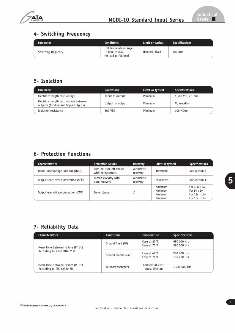
4- Switching Frequency
6- Protection Functions
Characteristics Protection Device Recovery Limit or typical Specifications
Input undervoltage lock-out (UVLO)Turn-on, turn-off circuitwith no hysteresis
Automaticrecovery
Threshold See section 3
Output short circuit protection (SCP)Hiccup circuitry withauto-recovery
Automaticrecovery
Permanent See section 11
Output overvoltage protection (OVP) Zener clamp /
MaximumMaximumMaximumMaximum
For 3.3v : 4vFor 5v : 6vFor 12v : 14vFor 15v : 17v
7- Reliability Data
Parameter Conditions Limit or typical Specifications
Switching frequencyFull temperature rangeUi min. to max.No load to full load
Nominal, fixed 480 KHz
5- Isolation
Characteristics Conditions Temperature Specifications
Mean Time Between Failure (MTBF)According to MIL-HDBK-217F
Ground fixed (Gf)Case at 40°CCase at 70°C
950 000 Hrs380 000 Hrs
Ground mobile (Gm)Case at 40°CCase at 70°C
240 000 Hrs105 000 Hrs
Mean Time Between Failure (MTBF)According to IEC-62380-TR
Telecom switchersAmbient at 25°C100% time on
1 730 000 Hrs
Parameter Conditions Limit or typical Specifications
Electric strength test voltage Input to output Minimum 1 500 VDC / 1 min
Electric strength test voltage betweenoutputs (for dual and triple outputs)
Output to output Minimum No isolation
Isolation resistance 500 VDC Minimum 100 MOhm
For locations, phone, fax, E-Mail see back cover
6
IndustrialGradeMGDI-10 Standard Input Series
Gaia Converter FC97-006.01/16 Revision P©
5
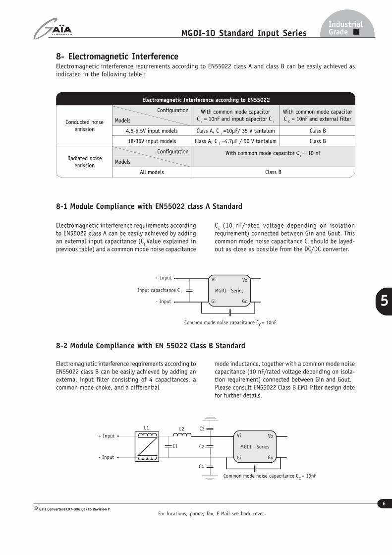
8- Electromagnetic InterferenceElectromagnetic interference requirements according to EN55022 class A and class B can be easily achieved asindicated in the following table :
Electromagnetic interference requirements accordingto EN55022 class A can be easily achieved by addingan external input capacitance (C
I Value explained in
previous table) and a common mode noise capacitance
Cc (10 nF/rated voltage depending on isolation
requirement) connected between Gin and Gout. Thiscommon mode noise capacitance C
c should be layed-
out as close as possible from the DC/DC converter.
8-1 Module Compliance with EN55022 class A Standard
8-2 Module Compliance with EN 55022 Class B Standard
Electromagnetic interference requirements according toEN55022 class B can be easily achieved by adding anexternal input filter consisting of 4 capacitances, acommon mode choke, and a differential
mode inductance, together with a common mode noisecapacitance (10 nF/rated voltage depending on isola-tion requirement) connected between Gin and Gout.Please consult EN55022 Class B EMI Filter design dotefor further details.
Input capacitance C i
Common mode noise capacitance C = 10nFc
- Input
+ Input
MGDI - Series
Vi Vo
Gi Go
Electromagnetic Interference according to EN55022
Conducted noiseemission
Configuration With common mode capacitorC
c = 10nF and input capacitor C
i
With common mode capacitorC
C = 10nF and external filterModels
4,5-5,5V input models Class A, C i =10µF/ 35 V tantalum Class B
18-36V input models Class A, C i =4.7µF / 50 V tantalum Class B
Radiated noiseemission
Configuration With common mode capacitor C c = 10 nF
Models
All models Class B
Common mode noise capacitance C = 10nFc
MGDI - Series
Vi Vo
Gi Go
C4
C2
C3L2
C1
L1
- Input
+ Input
For locations, phone, fax, E-Mail see back cover
7
IndustrialGradeMGDI-10 Standard Input Series
Gaia Converter FC97-006.01/16 Revision P©
5
9- Thermal Characteristics
Characteristics Conditions Limit or typical Performances
Operating ambient temperaturerange at full load
Ambient temperature *MinimumMaximum
- 40°C+ 71°C
Operating case temperaturerange at full load
Case temperatureMinimumMaximum
- 40°C+95°C
Storage temperature range Non functionningMinimumMaximum
- 40°C+ 105°C
Thermal resistanceRth case to ambient in free airnatural convection
Typical 12°C /W
Note * : The upper temperature range depends on configuration, the user must assure a max. case temperature of + 95°C.
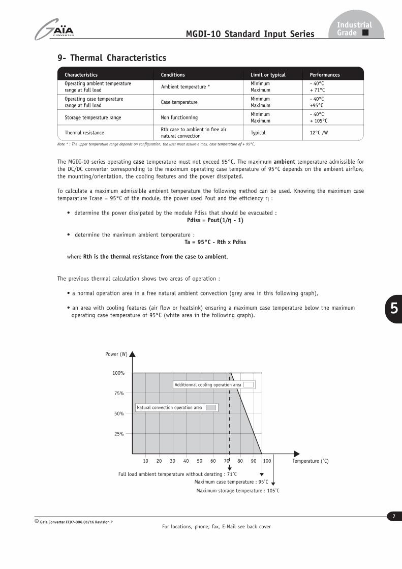
10 10030 807060 9020 40 50
25%
75%
50%
100%
Power (W)
Temperature (˚C)
Full load ambient temperature without derating : 71˚C
Maximum case temperature : 95˚C
Natural convection operation area
Additionnal cooling operation area
Maximum storage temperature : 105˚C
The MGDI-10 series operating case temperature must not exceed 95°C. The maximum ambient temperature admissible forthe DC/DC converter corresponding to the maximum operating case temperature of 95°C depends on the ambient airflow,the mounting/orientation, the cooling features and the power dissipated.
To calculate a maximum admissible ambient temperature the following method can be used. Knowing the maximum casetemparature Tcase = 95°C of the module, the power used Pout and the efficiency η :
• determine the power dissipated by the module Pdiss that should be evacuated :Pdiss = Pout(1/ηηηηη - 1)
• determine the maximum ambient temperature :Ta = 95°C - Rth x Pdiss
where Rth is the thermal resistance from the case to ambient.
The previous thermal calculation shows two areas of operation :
• a normal operation area in a free natural ambient convection (grey area in this following graph),
• an area with cooling features (air flow or heatsink) ensuring a maximum case temperature below the maximum operating case temperature of 95°C (white area in the following graph).
For locations, phone, fax, E-Mail see back cover
8
IndustrialGradeMGDI-10 Standard Input Series
Gaia Converter FC97-006.01/16 Revision P©
5
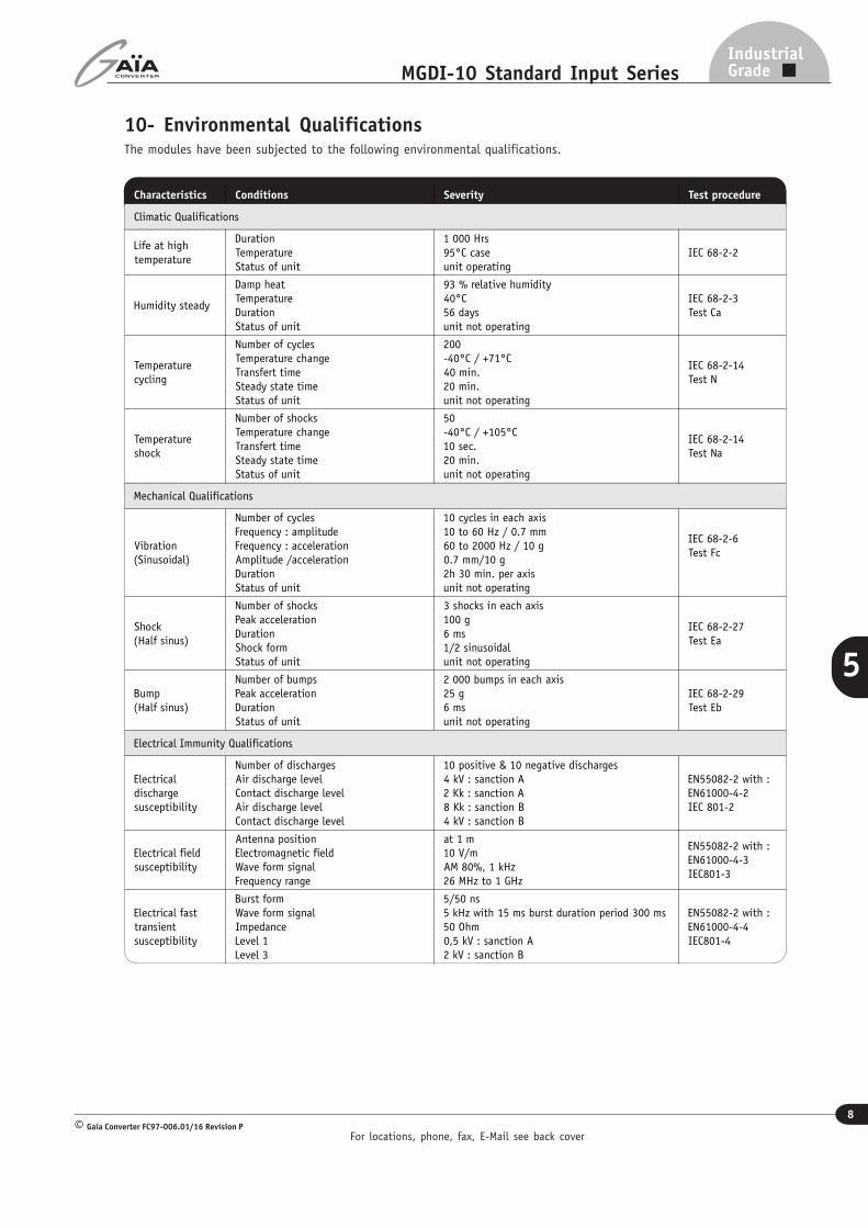
10- Environmental QualificationsThe modules have been subjected to the following environmental qualifications.
Characteristics Conditions Severity Test procedure
Climatic Qualifications
Life at high
temperature
Duration
Temperature
Status of unit
1 000 Hrs
95°C caseunit operating
IEC 68-2-2
Humidity steady
Damp heatTemperatureDurationStatus of unit
93 % relative humidity40°C56 daysunit not operating
IEC 68-2-3Test Ca
Temperaturecycling
Number of cyclesTemperature changeTransfert timeSteady state timeStatus of unit
200-40°C / +71°C40 min.20 min.unit not operating
IEC 68-2-14Test N
Temperatureshock
Number of shocksTemperature changeTransfert timeSteady state timeStatus of unit
50-40°C / +105°C10 sec.20 min.unit not operating
IEC 68-2-14Test Na
Mechanical Qualifications
Vibration(Sinusoidal)
Number of cyclesFrequency : amplitudeFrequency : accelerationAmplitude /accelerationDurationStatus of unit
10 cycles in each axis10 to 60 Hz / 0.7 mm60 to 2000 Hz / 10 g0.7 mm/10 g2h 30 min. per axisunit not operating
IEC 68-2-6Test Fc
Shock(Half sinus)
Number of shocksPeak accelerationDurationShock formStatus of unit
3 shocks in each axis100 g6 ms1/2 sinusoidalunit not operating
IEC 68-2-27Test Ea
Bump(Half sinus)
Number of bumpsPeak accelerationDurationStatus of unit
2 000 bumps in each axis25 g6 msunit not operating
IEC 68-2-29Test Eb
Electrical Immunity Qualifications
Electricaldischargesusceptibility
Number of dischargesAir discharge levelContact discharge levelAir discharge levelContact discharge level
10 positive & 10 negative discharges4 kV : sanction A2 Kk : sanction A8 Kk : sanction B4 kV : sanction B
EN55082-2 with :EN61000-4-2IEC 801-2
Electrical fieldsusceptibility
Antenna positionElectromagnetic fieldWave form signalFrequency range
at 1 m10 V/mAM 80%, 1 kHz26 MHz to 1 GHz
EN55082-2 with :EN61000-4-3IEC801-3
Electrical fasttransientsusceptibility
Burst formWave form signalImpedanceLevel 1Level 3
5/50 ns5 kHz with 15 ms burst duration period 300 ms50 Ohm0,5 kV : sanction A2 kV : sanction B
EN55082-2 with :EN61000-4-4IEC801-4
For locations, phone, fax, E-Mail see back cover
9
IndustrialGradeMGDI-10 Standard Input Series
Gaia Converter FC97-006.01/16 Revision P©
5
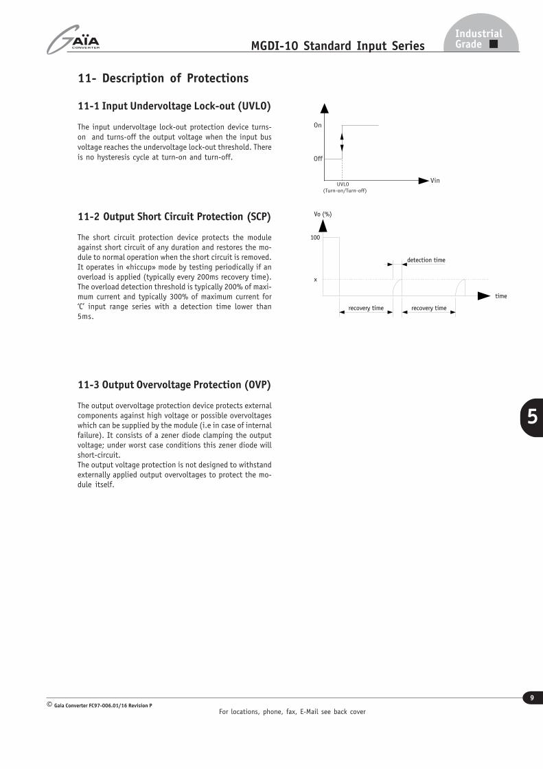
11- Description of Protections
11-1 Input Undervoltage Lock-out (UVLO)
The input undervoltage lock-out protection device turns-on and turns-off the output voltage when the input busvoltage reaches the undervoltage lock-out threshold. Thereis no hysteresis cycle at turn-on and turn-off.
11-2 Output Short Circuit Protection (SCP)
The short circuit protection device protects the moduleagainst short circuit of any duration and restores the mo-dule to normal operation when the short circuit is removed.It operates in «hiccup» mode by testing periodically if anoverload is applied (typically every 200ms recovery time).The overload detection threshold is typically 200% of maxi-mum current and typically 300% of maximum current for‘C’ input range series with a detection time lower than5ms.
11-3 Output Overvoltage Protection (OVP)
The output overvoltage protection device protects externalcomponents against high voltage or possible overvoltageswhich can be supplied by the module (i.e in case of internalfailure). It consists of a zener diode clamping the outputvoltage; under worst case conditions this zener diode willshort-circuit.The output voltage protection is not designed to withstandexternally applied output overvoltages to protect the mo-dule itself.
Vin
On
Off
UVLO
(Turn-on/Turn-off)
time
recovery time
detection time
recovery time
x
100
Vo (%)
For locations, phone, fax, E-Mail see back cover
10
IndustrialGradeMGDI-10 Standard Input Series
Gaia Converter FC97-006.01/16 Revision P©
5
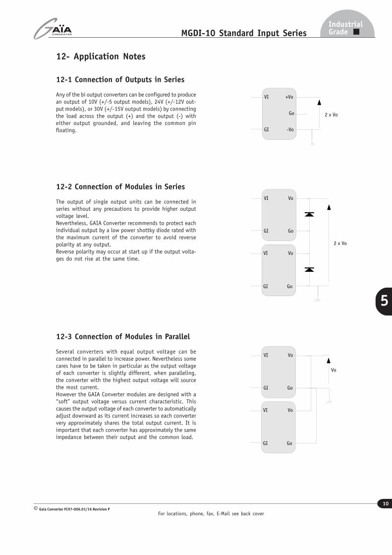
12- Application Notes
12-1 Connection of Outputs in Series
Any of the bi output converters can be configured to producean output of 10V (+/-5 output models), 24V (+/-12V out-put models), or 30V (+/-15V output models) by connectingthe load across the output (+) and the output (-) witheither output grounded, and leaving the common pinfloating.
12-2 Connection of Modules in Series
The output of single output units can be connected inseries without any precautions to provide higher outputvoltage level.Nevertheless, GAIA Converter recommends to protect eachindividual output by a low power shottky diode rated withthe maximum current of the converter to avoid reversepolarity at any output.Reverse polarity may occur at start up if the output volta-ges do not rise at the same time.
12-3 Connection of Modules in Parallel
Several converters with equal output voltage can beconnected in parallel to increase power. Nevertheless somecares have to be taken in particular as the output voltageof each converter is slightly different, when paralleling,the converter with the highest output voltage will sourcethe most current.However the GAIA Converter modules are designed with a“soft’’ output voltage versus current characteristic. Thiscauses the output voltage of each converter to automaticallyadjust downward as its current increases so each convertervery approximately shares the total output current. It isimportant that each converter has approximately the sameimpedance between their output and the common load.
Go
+Vo
-VoGI
VI
2 x Vo
Go
Vo
GI
VI
Go
Vo
GI
VI
Vo
Go
Vo
GI
VI
Go
Vo
GI
VI
2 x Vo
For locations, phone, fax, E-Mail see back cover
11
IndustrialGradeMGDI-10 Standard Input Series
Gaia Converter FC97-006.01/16 Revision P©
5
Pin dimensions : O 0,73 mm (0.03 ”)
40
(1.58")
35.56
(1,40")
7,60
(0.30")
5 min
(0.20")
20,32
(0.80")
26
(1.03")
8
(0.32")
26,20
(1.03")
10,16
(0.40")
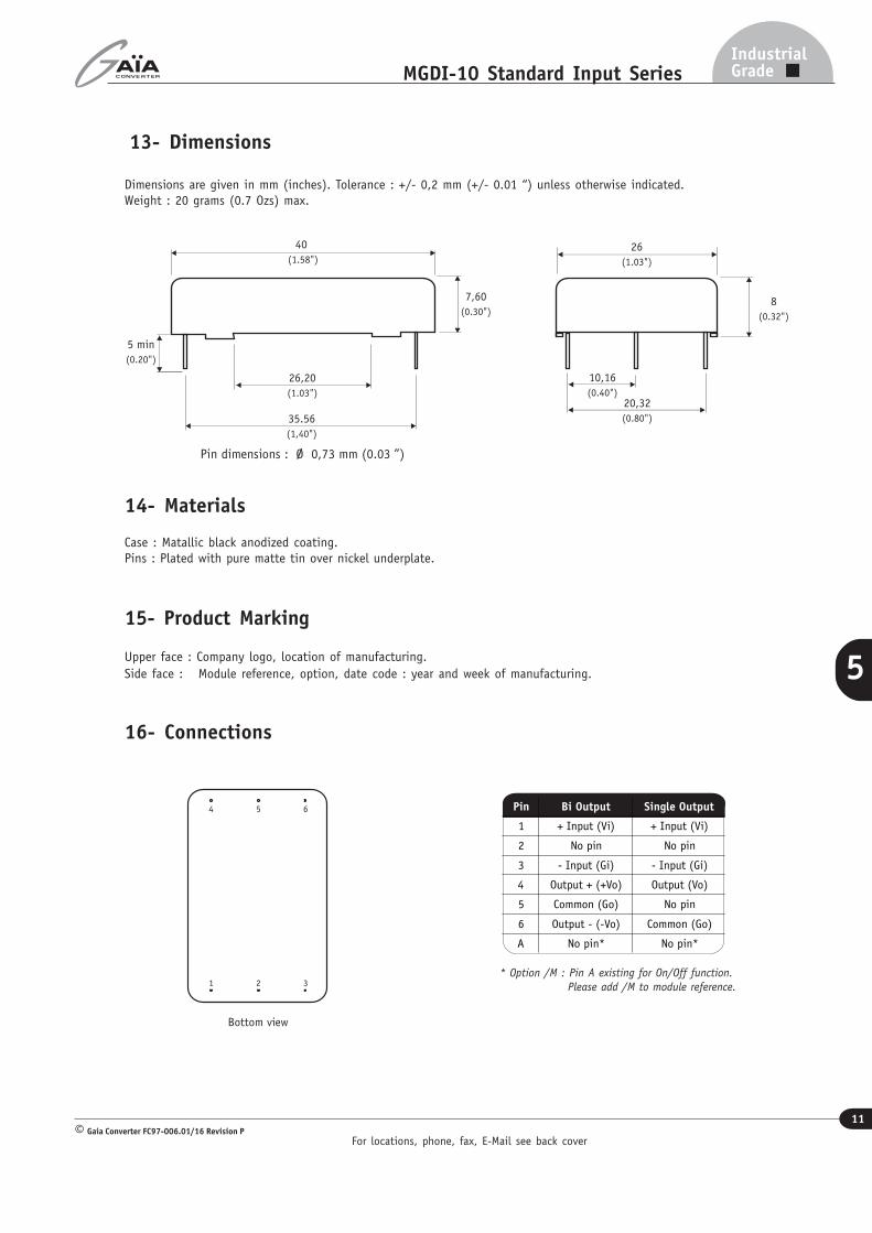
13- Dimensions
Dimensions are given in mm (inches). Tolerance : +/- 0,2 mm (+/- 0.01 “) unless otherwise indicated.Weight : 20 grams (0.7 Ozs) max.
14- Materials
Case : Matallic black anodized coating.Pins : Plated with pure matte tin over nickel underplate.
15- Product Marking
Upper face : Company logo, location of manufacturing.Side face : Module reference, option, date code : year and week of manufacturing.
16- Connections
1
Bottom view
32
4 65 Pin Bi Output Single Output
1 + Input (Vi) + Input (Vi)
2 No pin No pin
3 - Input (Gi) - Input (Gi)
4 Output + (+Vo) Output (Vo)
5 Common (Go) No pin
6 Output - (-Vo) Common (Go)
A No pin* No pin*
* Option /M : Pin A existing for On/Off function.Please add /M to module reference.
Information given in this datasheet is believed to be accurate and reliable. However, no responsibility is assumed for the consequence of its use nor for any infringement of patents or other rights of third parties which may result from its use.These products are sold only according to GAIA Converter general conditions of sale, unless otherwise confirmed by writing. Specifications subject to change without notice.
Prin
ted
in F
ranc
e by
GAIA
Con
vert
er F
C97-
004.
01/1
6 Re
visi
on P
Gra
phis
me
: Ph
ilip
pe C
licq
Represented by :
For more detailed specifications and applications information, contact :
International HeadquartersGAÏA Converter - France
ZI de la Morandière33185 LE HAILLAN - FRANCETel. : + (33)-5-57-92-12-80Fax : + (33)-5-57-92-12-89
North American HeadquartersGAÏA Converter Canada, Inc4038 Le Corbusier BlvdLAVAL, QUEBEC - CANADA H7L 5R2Tel. : (514)-333-3169Fax : (514)-333-4519