Embed Size (px)
Citation preview

8/17/2019 DC Generator Using DC-DC Converter
http://slidepdf.com/reader/full/dc-generator-using-dc-dc-converter 1/9
MultiCraft International Journal of Engineering, Science and Technology
Vol. 4, No. 1, 2012, pp. 65-73
INTERNATIONAL
JOURNAL OF
ENGINEERING,
SCIENCE AND
TECHNOLOGY
www.ijest-ng.com
www.ajol.info/index.php/ijest© 2012 MultiCraft Limited. All rights reserved
PMBLDCG based stand-alone wind energy conversion system for small
scale applications
Bhim Singh1, Shailendra Sharma
2*
1* Department of Electrical Engineering, Indian Institute of Technology Delhi, New Delhi-110016, INDIA2 Department of Electrical Engineering, Shri G. S. Institute of Technology & Science Indore, INDIA
*Corresponding Author: e-mail:[email protected], Tel +91-731-2548334, Fax.+91-731-2432540
_______________________________________________________________________________________________________
Abstract
This paper deals with a permanent magnet brushless DC generator (PMBLDCG) based stand-alone wind energy conversion
system (WECS) for small scale power generation. A buck-boost DC-DC converter is used for controlling the PMBLDCG speed
to achieve optimum energy output from the wind turbine without sensing wind speeds. An uncontrolled diode bridge rectifier is
used in between PMBLDCG terminals and input of a buck-boost converter. The buck boost converter feeds the generated power
to a battery energy storage system (BESS) and consumer loads. A single-phase voltage source inverter (VSI) is used at the DC bus to feed regulated voltage and frequency AC supply to consumer loads. The performance of the voltage and frequency
controller is demonstrated as a maximum power point tracker, a load leveler, an active filter along with a voltage and frequency
controller.
Keywords: Permanent Magnet Brushless DC Generator, Buck Boost Converter, Battery, Wind Power, Maximum Power Point
Tracking.
DOI: http://dx.doi.org/10.4314/ijest.v4i1.8S _______________________________________________________________________________________________________
1. Introduction
Permanent magnet machines are known as a PM brushless DC (PMBLDC) machines based on the shape of electromotive force
(EMF) induced in their stator winding (Gieras and Wing 2002). Due to the surface mounted PM on the rotor of PMBLDC
machine, the shape of EMF induced at stator terminals are trapezoidal in nature. In recent years, wind energy conversion systems
(WECS) are installed worldwide to deal with acute shortage of electrical energy (David et al 2001, Simoes and Farret 2004,
Bhadra et al 2004, Ackermann 2005). The permanent magnet brushless DC generator (PMBLDCG) has 15% higher power densitythan PMSM machines (Lai and Chan 2007) and due to trapezoidal EMF, the rectified DC output voltage has reduced ripples. This
reduces the size of the machine for a given power rating as compared to conventional synchronous machines and inductionmachines. These aspects provide PMBLDCG, a potential candidate for wind energy conversion systems (WECS) (Ojo et al 1997).
Some research publications have reported on use of PMBLDCG for power conversion [Kim et al 2007, Krishnan and Rim 1990,
Zhuoran et al 2009, Milivojevic et al future). However, there is a limited attempt on stand-alone WECS using PMBLDCG.
Therefore, this work focuses on using a PMBLDCG for stand-alone WECS.This paper deals with a voltage and frequency controller (VFC) for a permanent magnet brushless DC generator based stand-
alone wind energy conversion systems (SWECS’s). The VFC is realized using a buck-boost converter and a single-phase voltage
source inverter (VSI) with a battery energy storage system at DC link.
8/17/2019 DC Generator Using DC-DC Converter
http://slidepdf.com/reader/full/dc-generator-using-dc-dc-converter 2/9
Singh et al. / International Journal of Engineering, Science and Technology, Vol. 4, No. 1, 2012, pp. 65-7366
2. System Configuration and Principle of Operation
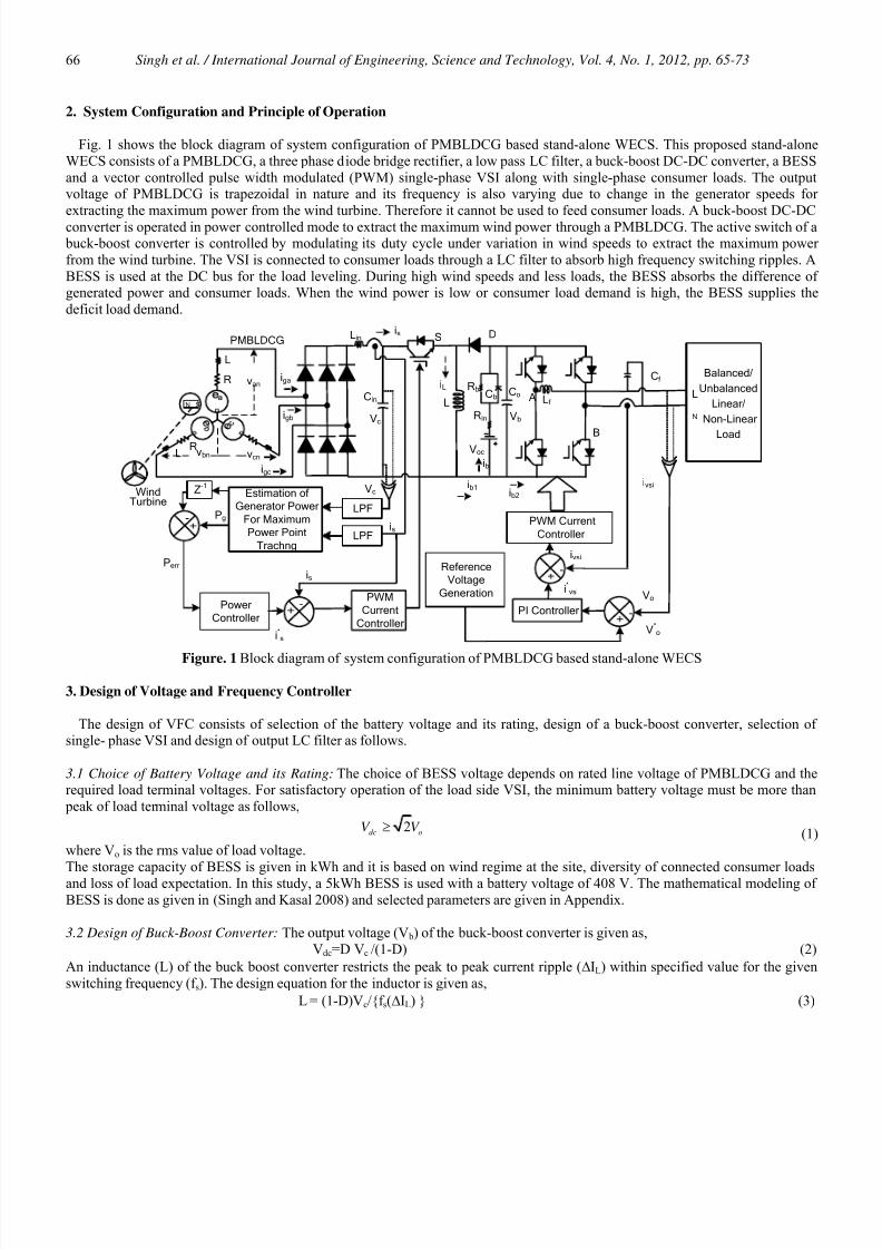
Fig. 1 shows the block diagram of system configuration of PMBLDCG based stand-alone WECS. This proposed stand-alone
WECS consists of a PMBLDCG, a three phase diode bridge rectifier, a low pass LC filter, a buck-boost DC-DC converter, a BESS
and a vector controlled pulse width modulated (PWM) single-phase VSI along with single-phase consumer loads. The outputvoltage of PMBLDCG is trapezoidal in nature and its frequency is also varying due to change in the generator speeds for
extracting the maximum power from the wind turbine. Therefore it cannot be used to feed consumer loads. A buck-boost DC-DC
converter is operated in power controlled mode to extract the maximum wind power through a PMBLDCG. The active switch of a buck-boost converter is controlled by modulating its duty cycle under variation in wind speeds to extract the maximum power
from the wind turbine. The VSI is connected to consumer loads through a LC filter to absorb high frequency switching ripples. A
BESS is used at the DC bus for the load leveling. During high wind speeds and less loads, the BESS absorbs the difference ofgenerated power and consumer loads. When the wind power is low or consumer load demand is high, the BESS supplies the
deficit load demand.
R
L
RL
iga
vbn vcn
PMBLDCG S
Rin
RbCb
Voc
Balanced/
Unbalanced
Linear/
Non-Linear
Load
Estimationof
GeneratorPower
ForMaximum
PowerPoint
Trachng
-
Z-1
Power
Controller
PWM
Current
Controller
Reference
Voltage
Generation
-PIController
-
PWMCurrent
Controller
WindTurbine
NS
Vc
is
Pg
Perr
i*sV*o
Vo
ivsi
ivsi
i*vsi
van
igb
igc
LPF
LPF
is
Vb
-
L
D
A
B
L
N
Lf
Cf
Lin
Vc
iL
ib
ib1ib2
is
CinCo
Figure. 1 Block diagram of system configuration of PMBLDCG based stand-alone WECS
3. Design of Voltage and Frequency Controller
The design of VFC consists of selection of the battery voltage and its rating, design of a buck-boost converter, selection ofsingle- phase VSI and design of output LC filter as follows.
3.1 Choice of Battery Voltage and its Rating: The choice of BESS voltage depends on rated line voltage of PMBLDCG and therequired load terminal voltages. For satisfactory operation of the load side VSI, the minimum battery voltage must be more than
peak of load terminal voltage as follows,
2dc oV V ≥ (1)
where Vo is the rms value of load voltage.
The storage capacity of BESS is given in kWh and it is based on wind regime at the site, diversity of connected consumer loads
and loss of load expectation. In this study, a 5kWh BESS is used with a battery voltage of 408 V. The mathematical modeling of
BESS is done as given in (Singh and Kasal 2008) and selected parameters are given in Appendix.
3.2 Design of Buck-Boost Converter: The output voltage (V b) of the buck-boost converter is given as,
Vdc=D Vc /(1-D) (2)
An inductance (L) of the buck boost converter restricts the peak to peak current ripple (ΔIL) within specified value for the given
switching frequency (f s). The design equation for the inductor is given as,
L = (1-D)Vc/f s(ΔIL) (3)

8/17/2019 DC Generator Using DC-DC Converter
http://slidepdf.com/reader/full/dc-generator-using-dc-dc-converter 3/9
Singh et al. / International Journal of Engineering, Science and Technology, Vol. 4, No. 1, 2012, pp. 65-7367
where Vc is the average output of the uncontrolled bridge rectifier and D is the duty cycle of the buck boost converter.
The buck-boost converter is designed for a 3 kW, 7 Nm rated torque PMBLDCG (data given in Appendix) with a base DC link
voltage of V b =408V at rated PMBLDCG speed (400 rad/s). Other design data are f s = 40 kHz, IL = 9.42A, ΔIL= 0.9 A (10% of IL).
The design value of an inductor is obtained as L = 6 mH.
The maximum current through the active switch and the diode is according to maximum current through the inductor. Similarly themaximum voltage which the switch and diode have to block is the battery voltage. Therefore the desired voltage ratings of IGBT
and diode are considered of 600 V.
3.3 Selection of Single Phase VSI: For feeding 3 kW, 0.8 lagging power factor loads using a single-phase two–leg VSI, the
maximum current through switching device is given as 1.25i pp+√2IVSI) (Singh et al 2004). Considering 5% peak to peak ripple in
the VSI current and IVSI equals to 16 A. Therefore, an IGBT of 35 A, 600 V is selected for a two-leg VSC as a VSI.
3.4 Design of LC Filter: To obtain sinusoidal load voltage, a LC filter is used between the load and VSI terminals. Further, the
resonant frequency of LC filter should be well below the lowest harmonic present in the PWM output voltage and it should be
very high than the desired fundamental frequency (Steinke 1999). The PWM frequency of single-phase VSI is selected 10 kHz and
fundamental load voltage frequency is 50 Hz. For the considered resonant frequency of 1000 Hz, the selected value of LC filter areas Lf = 3 mH and Cf =10 μF.
4. Control Algorithm
The objectives of control of the PMBLDCG based stand-alone WECS are maximum wind power extraction and to feeduninterruptable power to the targeted consumers. The control algorithm is divided in to two parts i.e. one deals with the control of
a buck-boost converter to control over the PMBLDCG power and the other section deals with control of single-phase VSI toregulate load voltage and frequency. The buck-boost converter is operated in power control mode by modulating the duty cycle of
its active switch in PWM mode. Three phase diode bridge rectifier DC output voltage (V c) and its current (is) are sensed and
filtered using a low pass filter with a cut-off frequency of 20 Hz and multiplied to obtain the instantaneous PMBLDCG power (Pg).
The estimated Pg(n) is compared with the already available sample of Pg(n-1) stored at pervious sampling time. The difference
power is fed to a power controller to obtain the reference current (i*s). The reference current (i*s) and sensed current (is) are
compared and fed to a proportional-integral (PI) controller to provide the reference modulation index (m) for a PWM controlled
active switch. This control algorithm does not require measurement of wind speed, rotor speed and sensing of PMBLDCG stator
terminal voltages and currents for maximum power point tracking. Further, the buck-boost converter allows power generationunder large variation in wind speeds. When there is a rise in the wind power, the modulation index (m) increases to absorb higher
power and vice-versa. The single-phase VSI is controlled in vector controlled mode. The reference voltage signal of desired
frequency (v*o) is compared with the sensed terminal voltage (vo) and the error voltage (ver ) is processed through a PI controller to
obtain the reference VSI current (i*vsi). The reference VSI current is compared with sensed VSI current (ivsi) to obtain current error
to feed the PWM controller block to generate the switching signals for insulated gate bipolar transistors (IGBT’s) of single-phase
VSI. Basic equations used in modeling of the VFC are given as follows.
4.1 Maximum Power Point Tracking Control of PMBLDCG: The output voltage (Vc) of an uncontrolled rectifier is sensed andfiltered. Similarly current (is) is sensed and filtered. The instantaneous generated power (Pg) is estimated at nth sampling instant as
follows,
Pg(n) =Vc(n)is(n) (4)The estimated Pg at nth sampling instant and (n-1)th sampling instant are compared and the difference of these powers are termed as
Per (n). This Per (n) is the input to the power proportional- integral (PI) controller. The output of the power PI controller at the n th
sampling instant is given as,
i*s(n) = i*
s(n-1) + K pgPer (n) – Per (n-1)+K igPer (n) (5)
where i
*
s is the reference current and K pg and K ig are the proportional and integral gain constants of a PI controller respectively.The reference current i*s and sensed current is are compared and the current error(ier ) is amplified to obtain the desired modulation
index (m) to control the duty cycle of an active switch of the buck-boost converter.
4.2 Control of Single Phase VSI : The objectives of controlling single-phase VSI are to regulate the output voltage and itsfrequency, to feed linear and non-linear loads. The reference load voltage is given as,
v*o(n)=Vmsin(2πft) (6)
where Vm is the maximum value of the reference AC voltage (i.e. 325V in this case) and f is the reference frequency of the load
voltage (i.e. 50Hz in this case).
The reference and sensed voltage are compared individually at nth sampling instant as follows,
voer (n)= v*o(n)- vo(n) (7)

8/17/2019 DC Generator Using DC-DC Converter
http://slidepdf.com/reader/full/dc-generator-using-dc-dc-converter 4/9
Singh et al. / International Journal of Engineering, Science and Technology, Vol. 4, No. 1, 2012, pp. 65-7368
This error voltage (voer ) are fed to a PI controller to obtain the reference VSI current (i *vsi) which output at nth sampling instant is
given as follows,
i*vsi(n) = i*
vsi(n-1) + K pvoer (n) – voer (n-1)+K i voer (n) (8)
These reference VSI current (i*vsi) and sensed VSI current (ivsi) are compared and the current error (ivsie) is amplified using gain K 1
and amplified current error is fed to PWM controller with fixed frequency triangular carrier wave (10 kHz) of unit amplitude togenerate the uni-polar switching signals for IGBT’s of single-phase VSI. The unipolar switching scheme is used to reduce the
effective switching frequency of the IGBT’s and hence switching losses of VSI.
5. Modeling of PMBLDCG Based WECS
The PMBLDCG based stand-alone WECS is modeled in MATLAB R2007 using Sim-Power system toolbox and a discrete stepsolver. The modeling of electrical and mechanical parts of the WECS is given herewith and the parameters used in this study are
given in Appendix.
5.1 Modeling of Variable Speed Wind Turbine: The mechanical power developed by a wind turbine in per unit system [2] is given
as,Pm= 0.5 ρAC p(λ, β)v3
wind (9)
where Pm is the power expressed for specific density of air (ρ) and the swept area of turbine blades (A). C p is power coefficient and
vwind refers wind speed in m/s.To optimize the power output from a fixed pitch angle (β) wind turbine, the turbine speed must vary as the wind speed changes to
keep the tip speed ratio (λ) constant. A generic equation is used to model the wind turbine C p(λ,β).The equation used to model thewind turbine characteristics is as,
5 1/
1 2 1 3 4 6
3
7 8
( , ) ( / )
(1/ ) 1/( ) /( 1)
C
p
i
C C c C C e C
C C
λ λ β λ λ
λ λ β β
= − − +
= − − + (10)
In this model β=0.The λ is defined as tip speed ratio (ratio of angular speed of turbine/wind speed) and C1-C8 are wind turbine
constants. The values of these constants are given in Appendix.
5.2 Modeling of PMBLDCG: From the equivalent circuit (shown in Fig. 1), the PMBLDCG is modeled in the form of a voltageequations (Putta Swamy et al 1995) given as,
ean = van- Ria - pλa (11)
e bn = v bn- Ri b - pλ b (12)
ecn = vcn- Ric - pλc (13)
where R is the resistance of motor windings/phase and p is the derivative operator. The ia, i b and ic are each phase currents, λa, λ b and λc are flux linkages with each phase windings and ean, e bn and ecn are phase to neutral induced emfs of PMBLDCG while van,
v bn and vcn are the terminal voltages in respective phases defined as.van= va0- vn0, v bn= v b0- vn0, vcn= vc0- vn0 (14)
where va0, v b0, vc0, vn0 are three phase and neutral voltages refered to zero potential at mid-point of DC link.
The flux linkages are represented as,
λa = Lsia - M (i b + ic) (15)λ b = Lsi b - M (ia + ic) (16)
λc = Lsic - M (i b + ia) (17)
where Ls is the self inductance of each phase winding and M is the mutual inductnace between each phase winding.
The PMBLDCG has no neutral connection and therefore it can be written as,ia+ i b+ ic=0 (18)
By substituing Eqs. (15-17) in Eqs. (11-13), the volt ampere equations results in state space current derivitve form as [14],
pia= 1/(Ls+M)ean-iaR-van (19) pi b= 1/(Ls+M)e bn-i bR-v bn (20)
pic= 1/(Ls+M)ecn-icR-vcn (21)
Three-phase generated voltage ea, e b and ec are in trapezoidal shape. For this, three-phase back emf are expressed as a function of
rotor position (θr ) as,
ean=k b f a(θr )ωr , e bn=k b f b(θr )ωr , e bn=k b f b(θr )ωr , (22)where f a(θr )=1 for 0 <θr <2π/3, (23)
f a(θr )=(6/ π)( π- θr )-1 for 2π/3 <θr < π, (24) f a(θr )=-1 for π <θr <5π/3, (25)
f a(θr )=(6/ π)( θr -2 π)+1 for 5π/3 <θr < 2π (26)Similarly f b(θr ) and f c(θr ) may be expressed as a function of rotor position θr . The developed electromagnetic torque is expressed as
follows.
8/17/2019 DC Generator Using DC-DC Converter
http://slidepdf.com/reader/full/dc-generator-using-dc-dc-converter 5/9
Singh et al. / International Journal of Engineering, Science and Technology, Vol. 4, No. 1, 2012, pp. 65-7369
Te=k b( f a(θr )ia+ f b(θr )i b+ f c(θr )ic (27)
and pωr =(P/2)( Tw- Te-B ωr )/J (28)
where Tw is the wind turbine torque, K b is back-emf constant, B is the coefficient of friction and J is the combined inertia of wind
turbine and a PMBLDCG.
6. Results and Discussion
The performance of the VFC for a PMBLDCG based stand-alone WECS with BESS is evaluated for different conditions underchange in loads and change in wind speeds. The performance of the VFC is observed in terms of generated voltage and current for
phase ‘a’ of PMBLDCG, wind speed (Vw) in m/s, generator speed (ωr ) in rad/s, buck boost inductor current (iL), battery voltage
(V b), load voltage (vo), load current (io), generated power (Pg), battery charging power (P b) and load power (Po).
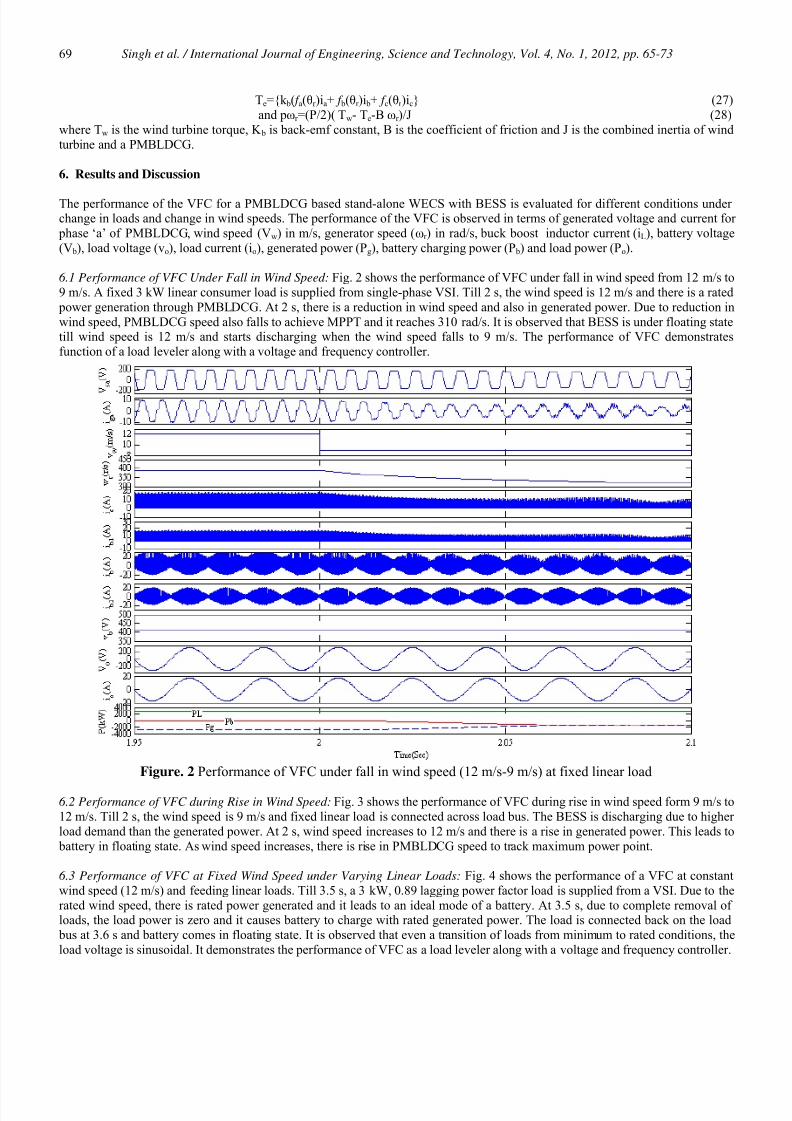
6.1 Performance of VFC Under Fall in Wind Speed: Fig. 2 shows the performance of VFC under fall in wind speed from 12 m/s to
9 m/s. A fixed 3 kW linear consumer load is supplied from single-phase VSI. Till 2 s, the wind speed is 12 m/s and there is a rated
power generation through PMBLDCG. At 2 s, there is a reduction in wind speed and also in generated power. Due to reduction in
wind speed, PMBLDCG speed also falls to achieve MPPT and it reaches 310 rad/s. It is observed that BESS is under floating statetill wind speed is 12 m/s and starts discharging when the wind speed falls to 9 m/s. The performance of VFC demonstrates
function of a load leveler along with a voltage and frequency controller.
Figure. 2 Performance of VFC under fall in wind speed (12 m/s-9 m/s) at fixed linear load
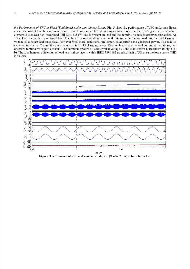
6.2 Performance of VFC during Rise in Wind Speed: Fig. 3 shows the performance of VFC during rise in wind speed form 9 m/s to
12 m/s. Till 2 s, the wind speed is 9 m/s and fixed linear load is connected across load bus. The BESS is discharging due to higher
load demand than the generated power. At 2 s, wind speed increases to 12 m/s and there is a rise in generated power. This leads to
battery in floating state. As wind speed increases, there is rise in PMBLDCG speed to track maximum power point.
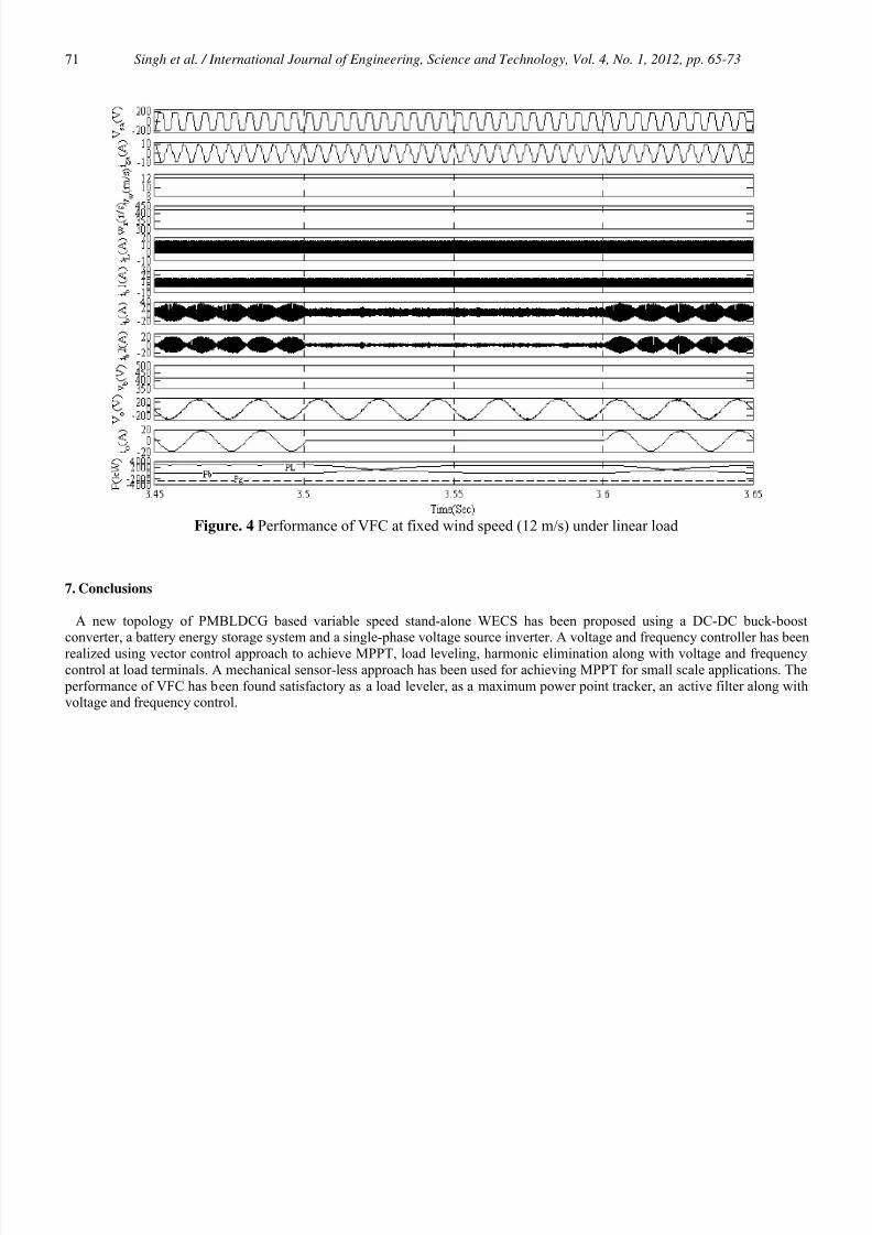
6.3 Performance of VFC at Fixed Wind Speed under Varying Linear Loads: Fig. 4 shows the performance of a VFC at constant
wind speed (12 m/s) and feeding linear loads. Till 3.5 s, a 3 kW, 0.89 lagging power factor load is supplied from a VSI. Due to the
rated wind speed, there is rated power generated and it leads to an ideal mode of a battery. At 3.5 s, due to complete removal ofloads, the load power is zero and it causes battery to charge with rated generated power. The load is connected back on the load
bus at 3.6 s and battery comes in floating state. It is observed that even a transition of loads from minimum to rated conditions, the
load voltage is sinusoidal. It demonstrates the performance of VFC as a load leveler along with a voltage and frequency controller.
8/17/2019 DC Generator Using DC-DC Converter
http://slidepdf.com/reader/full/dc-generator-using-dc-dc-converter 6/9
Singh et al. / International Journal of Engineering, Science and Technology, Vol. 4, No. 1, 2012, pp. 65-7370
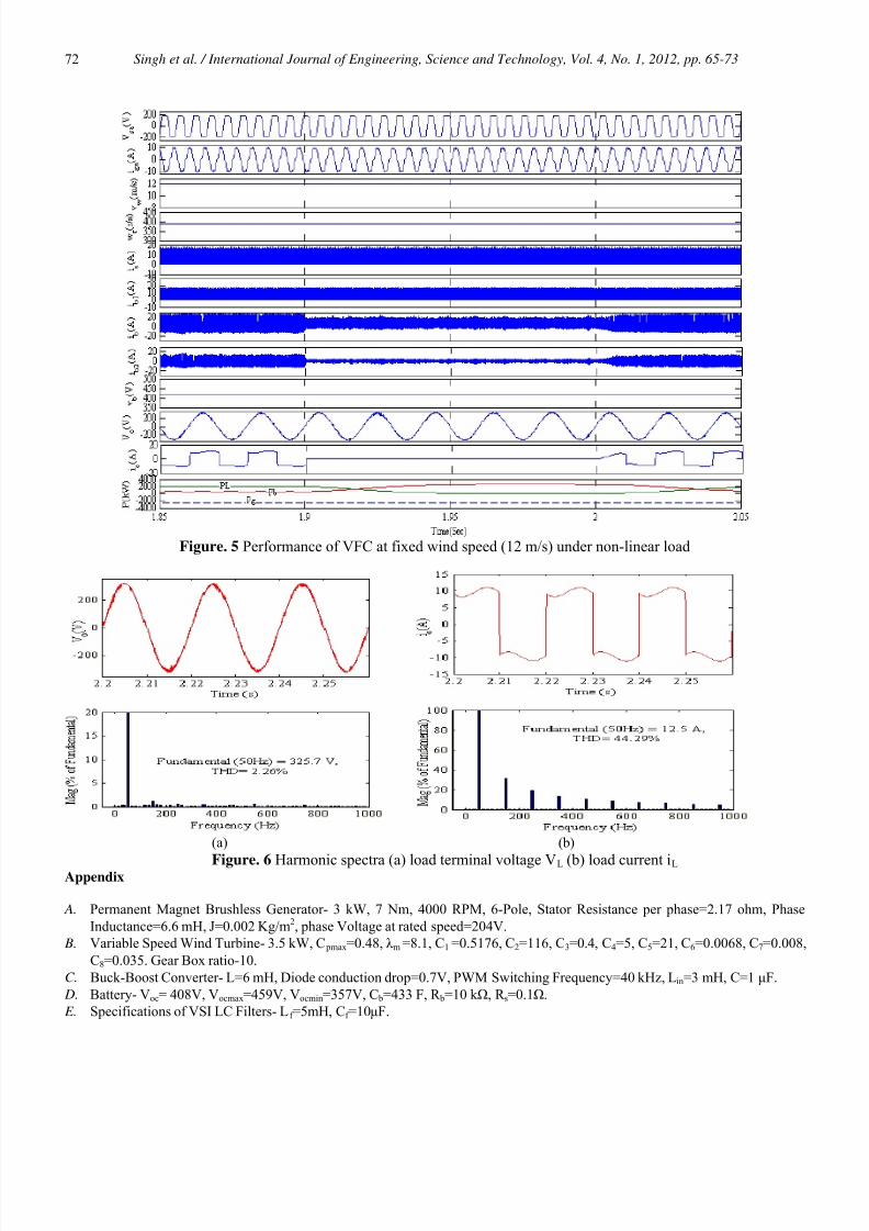
6.4 Performance of VFC at Fixed Wind Speed under Non-Linear Loads: Fig. 5 show the performance of VFC under non-linear
consumer load at load bus and wind speed is kept constant at 12 m/s. A single-phase diode rectifier feeding resistive-inductive
element is used as a non-linear load. Till 1.9 s, a 2 kW load is present on load bus and terminal voltage is observed ripple free. At
1.9 s, load is completely removed from load bus. It is observed that even with minimum current on load bus, the load terminalvoltage is constant and sinusoidal. However with these conditions, the battery is absorbing the generated power. The load is
switched in again at 2 s and there is a reduction in BESS charging power. Even with such a large load current perturbations, the
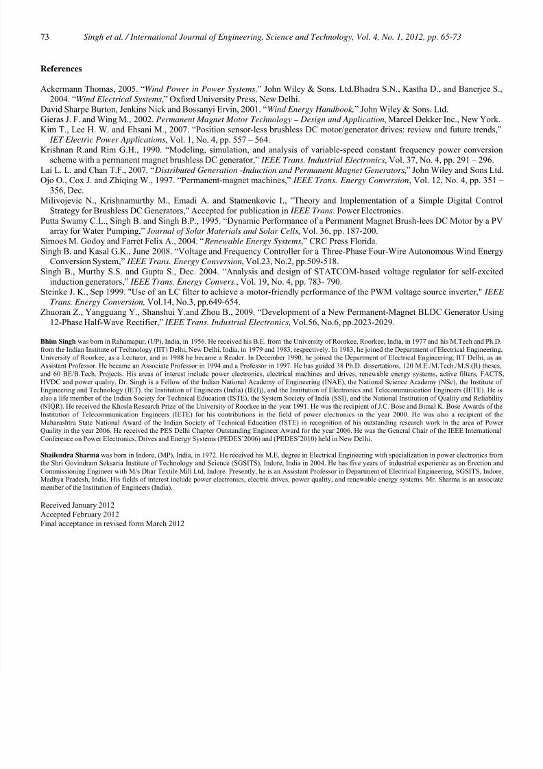
observed terminal voltage is constant. The harmonic spectra of load terminal voltage Vo and load current io are shown in Fig. 6(a- b). The total harmonic distortion of load terminal voltage is within IEEE 519-1992 standard limit of 5% even the load current THD
is 44.29%.
Figure. 3 Performance of VFC under rise in wind speed (9 m/s-12 m/s) at fixed linear load
8/17/2019 DC Generator Using DC-DC Converter
http://slidepdf.com/reader/full/dc-generator-using-dc-dc-converter 7/9
Singh et al. / International Journal of Engineering, Science and Technology, Vol. 4, No. 1, 2012, pp. 65-7371
Figure. 4 Performance of VFC at fixed wind speed (12 m/s) under linear load
7. Conclusions
A new topology of PMBLDCG based variable speed stand-alone WECS has been proposed using a DC-DC buck-boostconverter, a battery energy storage system and a single-phase voltage source inverter. A voltage and frequency controller has been
realized using vector control approach to achieve MPPT, load leveling, harmonic elimination along with voltage and frequencycontrol at load terminals. A mechanical sensor-less approach has been used for achieving MPPT for small scale applications. The
performance of VFC has been found satisfactory as a load leveler, as a maximum power point tracker, an active filter along withvoltage and frequency control.
8/17/2019 DC Generator Using DC-DC Converter
http://slidepdf.com/reader/full/dc-generator-using-dc-dc-converter 8/9
Singh et al. / International Journal of Engineering, Science and Technology, Vol. 4, No. 1, 2012, pp. 65-7372
Figure. 5 Performance of VFC at fixed wind speed (12 m/s) under non-linear load
(a) (b)
Figure. 6 Harmonic spectra (a) load terminal voltage VL (b) load current iL
Appendix
A. Permanent Magnet Brushless Generator- 3 kW, 7 Nm, 4000 RPM, 6-Pole, Stator Resistance per phase=2.17 ohm, Phase
Inductance=6.6 mH, J=0.002 Kg/m2, phase Voltage at rated speed=204V.
B. Variable Speed Wind Turbine- 3.5 kW, C pmax=0.48, λm =8.1, C1 =0.5176, C2=116, C3=0.4, C4=5, C5=21, C6=0.0068, C7=0.008,
C8=0.035. Gear Box ratio-10.
C. Buck-Boost Converter- L=6 mH, Diode conduction drop=0.7V, PWM Switching Frequency=40 kHz, Lin=3 mH, C=1 μF.
D. Battery- Voc= 408V, Vocmax=459V, Vocmin=357V, C b=433 F, R b=10 k Ω, R s=0.1Ω.
E. Specifications of VSI LC Filters- Lf =5mH, Cf =10μF.
8/17/2019 DC Generator Using DC-DC Converter
http://slidepdf.com/reader/full/dc-generator-using-dc-dc-converter 9/9
Singh et al. / International Journal of Engineering, Science and Technology, Vol. 4, No. 1, 2012, pp. 65-7373
References
Ackermann Thomas, 2005. “Wind Power in Power Systems,” John Wiley & Sons. Ltd.Bhadra S.N., Kastha D., and Banerjee S.,
2004. “Wind Electrical Systems,” Oxford University Press, New Delhi.
David Sharpe Burton, Jenkins Nick and Bossanyi Ervin, 2001. “Wind Energy Handbook,” John Wiley & Sons. Ltd.Gieras J. F. and Wing M., 2002. Permanent Magnet Motor Technology – Design and Application, Marcel Dekker Inc., New York.
Kim T., Lee H. W. and Ehsani M., 2007. “Position sensor-less brushless DC motor/generator drives: review and future trends,” IET Electric Power Applications, Vol. 1, No. 4, pp. 557 – 564.
Krishnan R.and Rim G.H., 1990. “Modeling, simulation, and analysis of variable-speed constant frequency power conversion
scheme with a permanent magnet brushless DC generator,” IEEE Trans. Industrial Electronics, Vol. 37, No. 4, pp. 291 – 296.
Lai L. L. and Chan T.F., 2007. “ Distributed Generation -Induction and Permanent Magnet Generators,” John Wiley and Sons Ltd.Ojo O., Cox J. and Zhiqing W., 1997. “Permanent-magnet machines,” IEEE Trans. Energy Conversion, Vol. 12, No. 4, pp. 351 –
356, Dec.
Milivojevic N., Krishnamurthy M., Emadi A. and Stamenkovic I., "Theory and Implementation of a Simple Digital Control
Strategy for Brushless DC Generators," Accepted for publication in IEEE Trans. Power Electronics.
Putta Swamy C.L., Singh B. and Singh B.P., 1995. “Dynamic Performance of a Permanent Magnet Brush-lees DC Motor by a PVarray for Water Pumping,” Journal of Solar Materials and Solar Cells, Vol. 36, pp. 187-200.
Simoes M. Godoy and Farret Felix A., 2004. “ Renewable Energy Systems,” CRC Press Florida.
Singh B. and Kasal G.K., June 2008. “Voltage and Frequency Controller for a Three-Phase Four-Wire Autonomous Wind EnergyConversion System,” IEEE Trans. Energy Conversion, Vol.23, No.2, pp.509-518.
Singh B., Murthy S.S. and Gupta S., Dec. 2004. “Analysis and design of STATCOM-based voltage regulator for self-excitedinduction generators,” IEEE Trans. Energy Convers., Vol. 19, No. 4, pp. 783- 790.
Steinke J. K., Sep 1999. "Use of an LC filter to achieve a motor-friendly performance of the PWM voltage source inverter," IEEE
Trans. Energy Conversion, Vol.14, No.3, pp.649-654.
Zhuoran Z., Yangguang Y., Shanshui Y.and Zhou B., 2009. “Development of a New Permanent-Magnet BLDC Generator Using
12-Phase Half-Wave Rectifier,” IEEE Trans. Industrial Electronics, Vol.56, No.6, pp.2023-2029.
Bhim Singh was born in Rahamapur, (UP), India, in 1956. He received his B.E. from the University of Roorkee, Roorkee, India, in 1977 and his M.Tech and Ph.D.
from the Indian Institute of Technology (IIT) Delhi, New Delhi, India, in 1979 and 1983, respectively. In 1983, he joined the Department of Electrical Engineering,University of Roorkee, as a Lecturer, and in 1988 he became a Reader. In December 1990, he joined the Department of Electrical Engineering, IIT Delhi, as an
Assistant Professor. He became an Associate Professor in 1994 and a Professor in 1997. He has guided 38 Ph.D. dissertations, 120 M.E./M.Tech./M.S.(R) theses,
and 60 BE/B.Tech. Projects. His areas of interest include power electronics, electrical machines and drives, renewable energy systems, active filters, FACTS,
HVDC and power quality. Dr. Singh is a Fellow of the Indian National Academy of Engineering (INAE), the National Science Academy (NSc), the Institute ofEngineering and Technology (IET). the Institution of Engineers (India) (IE(I)), and the Institution of Electronics and Telecommunication Engineers (IETE). He is
also a life member of the Indian Society for Technical Education (ISTE), the System Society of India (SSI), and the National Institution of Quality and Reliability
(NIQR). He received the Khosla Research Prize of the University of Roorkee in the year 1991. He was the recipient of J.C. Bose and Bimal K. Bose Awards of theInstitution of Telecommunication Engineers (IETE) for his contributions in the field of power electronics in the year 2000. He was also a recipient of the
Maharashtra State National Award of the Indian Society of Technical Education (ISTE) in recognition of his outstanding research work in the area of PowerQuality in the year 2006. He received the PES Delhi Chapter Outstanding Engineer Award for the year 2006. He was the General Chair of the IEEE International
Conference on Power Electronics, Drives and Energy Systems (PEDES’2006) and (PEDES’2010) held in New Delhi.
Shailendra Sharma was born in Indore, (MP), India, in 1972. He received his M.E. degree in Electrical Engineering with specialization in power electronics fromthe Shri Govindram Seksaria Institute of Technology and Science (SGSITS), Indore, India in 2004. He has five years of industrial experience as an Erection and
Commissioning Engineer with M/s Dhar Textile Mill Ltd, Indore. Presently, he is an Assistant Professor in Department of Electrical Engineering, SGSITS, Indore,Madhya Pradesh, India. His fields of interest include power electronics, electric drives, power quality, and renewable energy systems. Mr. Sharma is an associate
member of the Institution of Engineers (India).
Received January 2012
Accepted February 2012Final acceptance in revised form March 2012