Embed Size (px)
Citation preview
1 017-882-B1-001 Rev. C2 (12/2016)
CableUPS® Quick Start Guide
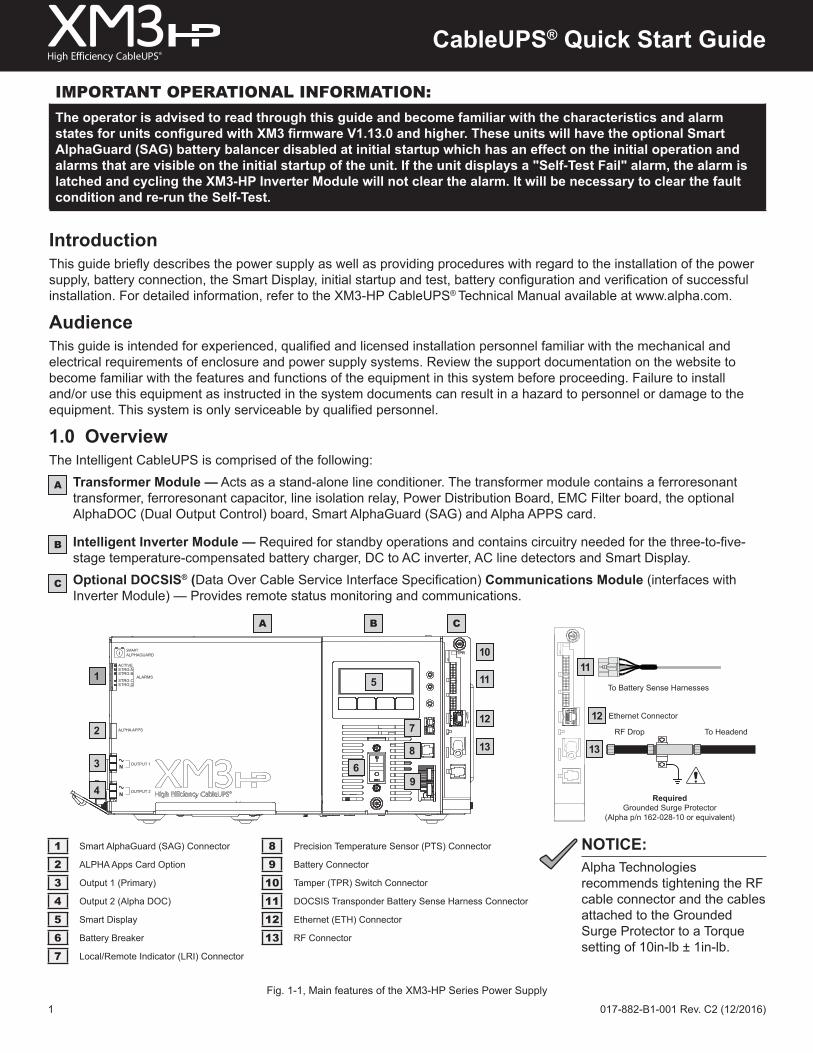
Fig. 1-1, Main features of the XM3-HP Series Power Supply
IntroductionThis guide briefly describes the power supply as well as providing procedures with regard to the installation of the power supply, battery connection, the Smart Display, initial startup and test, battery configuration and verification of successful installation. For detailed information, refer to the XM3-HP CableUPS® Technical Manual available at www.alpha.com.
AudienceThis guide is intended for experienced, qualified and licensed installation personnel familiar with the mechanical and electrical requirements of enclosure and power supply systems. Review the support documentation on the website to become familiar with the features and functions of the equipment in this system before proceeding. Failure to install and/or use this equipment as instructed in the system documents can result in a hazard to personnel or damage to the equipment. This system is only serviceable by qualified personnel.
1.0 OverviewThe Intelligent CableUPS is comprised of the following:
Transformer Module — Acts as a stand-alone line conditioner. The transformer module contains a ferroresonant transformer, ferroresonant capacitor, line isolation relay, Power Distribution Board, EMC Filter board, the optional AlphaDOC (Dual Output Control) board, Smart AlphaGuard (SAG) and Alpha APPS card.
Intelligent Inverter Module — Required for standby operations and contains circuitry needed for the three-to-five-stage temperature-compensated battery charger, DC to AC inverter, AC line detectors and Smart Display.Optional DOCSIS® (Data Over Cable Service Interface Specification) Communications Module (interfaces with Inverter Module) — Provides remote status monitoring and communications.
A
B
C
i SMARTALPHAGUARD
ACTIVESTRG ASTRG B
STRG CSTRG D
ALARMS
ALPHA APPS
N
N
OUTPUT 1
OUTPUT 2
TPR
ETH
A B C
1
2
3
4
5
6
7
8
9
10
11
13
IMPORTANT OPERATIONAL INFORMATION:The operator is advised to read through this guide and become familiar with the characteristics and alarm states for units configured with XM3 firmware V1.13.0 and higher. These units will have the optional Smart AlphaGuard (SAG) battery balancer disabled at initial startup which has an effect on the initial operation and alarms that are visible on the initial startup of the unit. If the unit displays a "Self-Test Fail" alarm, the alarm is latched and cycling the XM3-HP Inverter Module will not clear the alarm. It will be necessary to clear the fault condition and re-run the Self-Test.
To Battery Sense Harnesses
Required Grounded Surge Protector
(Alpha p/n 162-028-10 or equivalent)
To HeadendRF Drop
13
11
1 Smart AlphaGuard (SAG) Connector 8 Precision Temperature Sensor (PTS) Connector
2 ALPHA Apps Card Option 9 Battery Connector
3 Output 1 (Primary) 10 Tamper (TPR) Switch Connector
4 Output 2 (Alpha DOC) 11 DOCSIS Transponder Battery Sense Harness Connector
5 Smart Display 12 Ethernet (ETH) Connector
6 Battery Breaker 13 RF Connector
7 Local/Remote Indicator (LRI) Connector
12 Ethernet Connector12
NOTICE:Alpha Technologies recommends tightening the RF cable connector and the cables attached to the Grounded Surge Protector to a Torque setting of 10in-lb ± 1in-lb.
2 017-882-B1-001 Rev. C2 (12/2016)
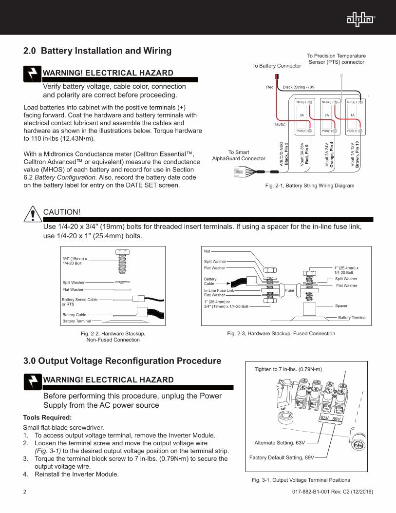
2.0 Battery Installation and Wiring
Load batteries into cabinet with the positive terminals (+) facing forward. Coat the hardware and battery terminals with electrical contact lubricant and assemble the cables and hardware as shown in the illustrations below. Torque hardware to 110 in-lbs (12.43N•m).
With a Midtronics Conductance meter (Celltron Essential™, Celltron Advanced™ or equivalent) measure the conductance value (MHOS) of each battery and record for use in Section 6.2 Battery Configuration. Also, record the battery date code on the battery label for entry on the DATE SET screen.
To Battery Connector
To Precision Temperature Sensor (PTS) connector
Vbat
t 3A
36V
Red
, Pin
9
3A 2A 1A
A/B/
C/D
NEG
Bla
ck, P
in 5
Vbat
t 2A
24V
Ora
nge,
Pin
4
Vbat
t 1A
12V
Bro
wn,
Pin
10
Black (String -) 0VRed
3A
POS(+)
NEG(-) NEG(-) NEG(-)
POS(+) POS(+)
36VDC
2A 1A
To Smart AlphaGuard Connector
Verify battery voltage, cable color, connection and polarity are correct before proceeding.
WARNING! ELECTRICAL HAZARD
Use 1/4-20 x 3/4" (19mm) bolts for threaded insert terminals. If using a spacer for the in-line fuse link, use 1/4-20 x 1" (25.4mm) bolts.
CAUTION!
Fig. 2-2, Hardware Stackup, Non-Fused Connection
3/4" (19mm) x 1/4-20 Bolt
Split Washer
Flat Washer
Battery Sense Cable or RTS
Battery CableBattery Terminal
Nut
Split WasherFlat Washer
Battery Cable
In-Line Fuse LinkFlat Washer
1" (25.4mm) or 3/4" (19mm) x 1/4-20 Bolt
1" (25.4mm) x 1/4-20 Bolt
Flat Washer
Split Washer
Spacer
Battery Terminal
Fuse
Fig. 2-3, Hardware Stackup, Fused Connection
3.0 Output Voltage Reconfiguration Procedure
Tools Required: Small flat-blade screwdriver.1. To access output voltage terminal, remove the Inverter Module. 2. Loosen the terminal screw and move the output voltage wire
(Fig. 3-1) to the desired output voltage position on the terminal strip.3. Torque the terminal block screw to 7 in-lbs. (0.79N•m) to secure the
output voltage wire.4. Reinstall the Inverter Module.
Fig. 2-1, Battery String Wiring Diagram
Fig. 3-1, Output Voltage Terminal Positions
63V 89V
Factory Default Setting, 89V
Alternate Setting, 63V
Tighten to 7 in-lbs. (0.79N•m)
Before performing this procedure, unplug the Power Supply from the AC power source
WARNING! ELECTRICAL HAZARD
3 017-882-B1-001 Rev. C2 (12/2016)
1. After wiring battery cable kit, battery sense cables and PTS, as shown in Section 2, verify DC/Battery breaker [6] is OFF.
2. Connect the Smart AlphaGuard (SAG) wire harness to SAG port [1]. If no SAG is installed, connect battery sense harness to the transponder [11].
3. Connect PTS to the PTS connector [8].4. Connect the Tamper Switch and RF cable to the transponder [10 and 12].5. Verify the SPI’s ON / ALT Toggle Switch is in the ALT position.6. Connect the SPI’s input cable to the Output 1 Connector [3]. If a 2nd
SPI / ALT Box is present connect input cable to Output 2 Connector [4]. 7. Plug the optional Local/Remote Indicator (LRI) cable into the LRI connector [7]. For
existing LRI installations, use LRI adapter kit, p/n 875-952-20.8. Turn AC breaker ON and verify it is the correct utility voltage at the outlet (per unit’s
nameplate voltage). If correct, plug in the XM3 line cord into the utility outlet.9. Verify correct battery voltage and polarity on battery cable connector (see Fig. 2-1) with a
digital voltmeter; if correct, plug the battery cable connector into Inverter Module [9].
4.0 Power Supply Connections (Refer to Fig. 1-1)
Fig. 4-1, SPI toggle switch (shown in ALT position)
ALT ON
5.0 Using the Smart DisplayAll operational functions, system testing, menus and alarms are available via the illuminated Smart Display. Display functions are accessible by following the indicated prompts above the four softkeys. Descriptions of the display functions are detailed below.
1 1st line: Indicates Model and Output Voltage/Current
2 Describes Power Supply Mode of Operation
3 Describes Status of Functions
4 Functionality top level menu PWR, BATT, COMM and APPS
5 Softkeys (Menu-driven system configuration)
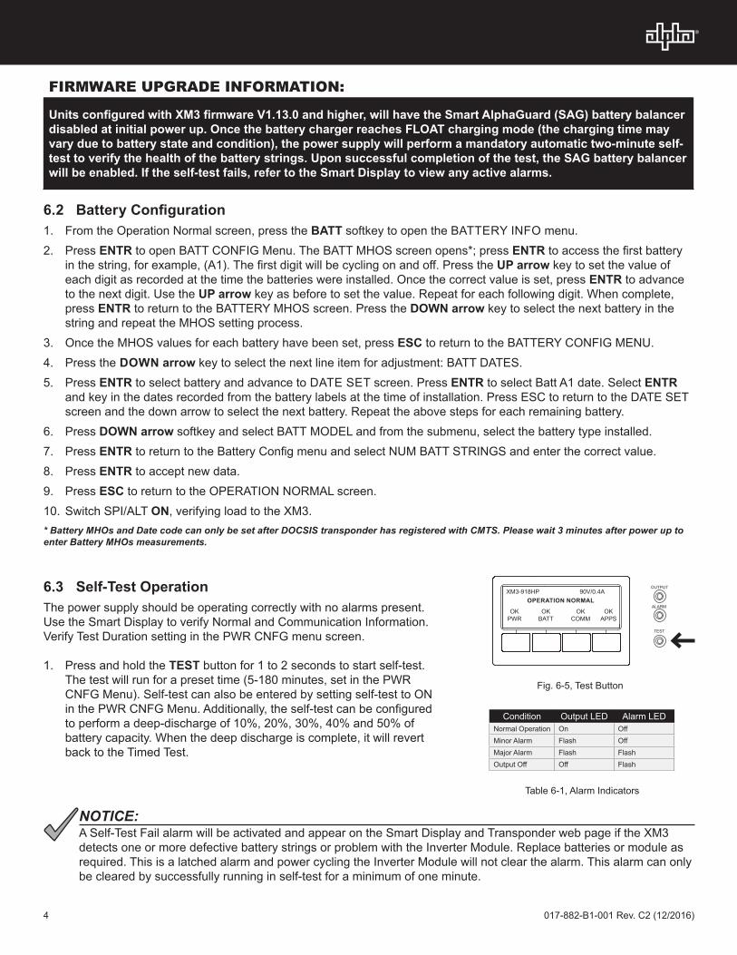
XM3-918HP 90V/10.0A
OPERATION NORMAL
OK OK OK OK PWR BATT COMM APPS
1
4
23
5
Fig. 6-1, Smart Display indicating a Self-Test Fail Alarm
SELFTEST FAIL ALARM
1. Check Batteries
2. Check InverterESC
Fig. 6-2, Self-Test Fail Alarm Menu, with suggestions for corrective actions
6.0 Startup, Battery Configuration and Self-Test
6.1 Initial startup1. After completing all the steps in Section 4.0, Power Supply
Connections, turn the DC/Battery breaker [6] ON. The Smart Display will cycle through its functions (approximately 60 seconds) verifying proper operation. During this time, the XM3 will perform an automatic 5 second Self-Test to verify whether a battery string is connected to the power supply system by checking the battery string voltage. Upon successful completion, the Smart Display will indicate “OPERATION NORMAL”. From this screen, proceed to Section 6.2, Battery Configuration.
2. If alarms are present and do not clear after 60 seconds, press the softkey associated with the alarm to see the ACTIVE ALARM list.
3. Press UP or DOWN to select the active alarm.4. Press ENTR to select the alarm and display diagnostic information.
Press ESC to return to the alarm list. Refer to the XM3-HP Power Supply Technical Manual for a complete listing of alarm conditions and recommended diagnostic solutions.
5. Once the alarm has been cleared, the batteries can be configured in the system as outlined in the next section.
Fig. 5-1, Smart Display With Sample Screen
** ACTIVE ALARMS **
SELF TEST FAIL
PWR INFO <MENU>ESC
4 017-882-B1-001 Rev. C2 (12/2016)
FIRMWARE UPGRADE INFORMATION:
Units configured with XM3 firmware V1.13.0 and higher, will have the Smart AlphaGuard (SAG) battery balancer disabled at initial power up. Once the battery charger reaches FLOAT charging mode (the charging time may vary due to battery state and condition), the power supply will perform a mandatory automatic two-minute self-test to verify the health of the battery strings. Upon successful completion of the test, the SAG battery balancer will be enabled. If the self-test fails, refer to the Smart Display to view any active alarms.
6.2 Battery Configuration1. From the Operation Normal screen, press the BATT softkey to open the BATTERY INFO menu. 2. Press ENTR to open BATT CONFIG Menu. The BATT MHOS screen opens*; press ENTR to access the first battery
in the string, for example, (A1). The first digit will be cycling on and off. Press the UP arrow key to set the value of each digit as recorded at the time the batteries were installed. Once the correct value is set, press ENTR to advance to the next digit. Use the UP arrow key as before to set the value. Repeat for each following digit. When complete, press ENTR to return to the BATTERY MHOS screen. Press the DOWN arrow key to select the next battery in the string and repeat the MHOS setting process.
3. Once the MHOS values for each battery have been set, press ESC to return to the BATTERY CONFIG MENU.4. Press the DOWN arrow key to select the next line item for adjustment: BATT DATES.5. Press ENTR to select battery and advance to DATE SET screen. Press ENTR to select Batt A1 date. Select ENTR
and key in the dates recorded from the battery labels at the time of installation. Press ESC to return to the DATE SET screen and the down arrow to select the next battery. Repeat the above steps for each remaining battery.
6. Press DOWN arrow softkey and select BATT MODEL and from the submenu, select the battery type installed.7. Press ENTR to return to the Battery Config menu and select NUM BATT STRINGS and enter the correct value.8. Press ENTR to accept new data.9. Press ESC to return to the OPERATION NORMAL screen.10. Switch SPI/ALT ON, verifying load to the XM3.
Condition Output LED Alarm LEDNormal Operation On OffMinor Alarm Flash OffMajor Alarm Flash FlashOutput Off Off Flash
OUTPUT
ALARM
TEST
XM3-918HP 90V/0.4AOPERATION NORMAL
OK PWR
OK BATT
OK COMM
OK APPS
A Self-Test Fail alarm will be activated and appear on the Smart Display and Transponder web page if the XM3 detects one or more defective battery strings or problem with the Inverter Module. Replace batteries or module as required. This is a latched alarm and power cycling the Inverter Module will not clear the alarm. This alarm can only be cleared by successfully running in self-test for a minimum of one minute.
NOTICE:
6.3 Self-Test OperationThe power supply should be operating correctly with no alarms present. Use the Smart Display to verify Normal and Communication Information. Verify Test Duration setting in the PWR CNFG menu screen.
1. Press and hold the TEST button for 1 to 2 seconds to start self-test. The test will run for a preset time (5-180 minutes, set in the PWR CNFG Menu). Self-test can also be entered by setting self-test to ON in the PWR CNFG Menu. Additionally, the self-test can be configured to perform a deep-discharge of 10%, 20%, 30%, 40% and 50% of battery capacity. When the deep discharge is complete, it will revert back to the Timed Test.
Fig. 6-5, Test Button
Table 6-1, Alarm Indicators
* Battery MHOs and Date code can only be set after DOCSIS transponder has registered with CMTS. Please wait 3 minutes after power up to enter Battery MHOs measurements.
5 017-882-B1-001 Rev. C2 (12/2016)
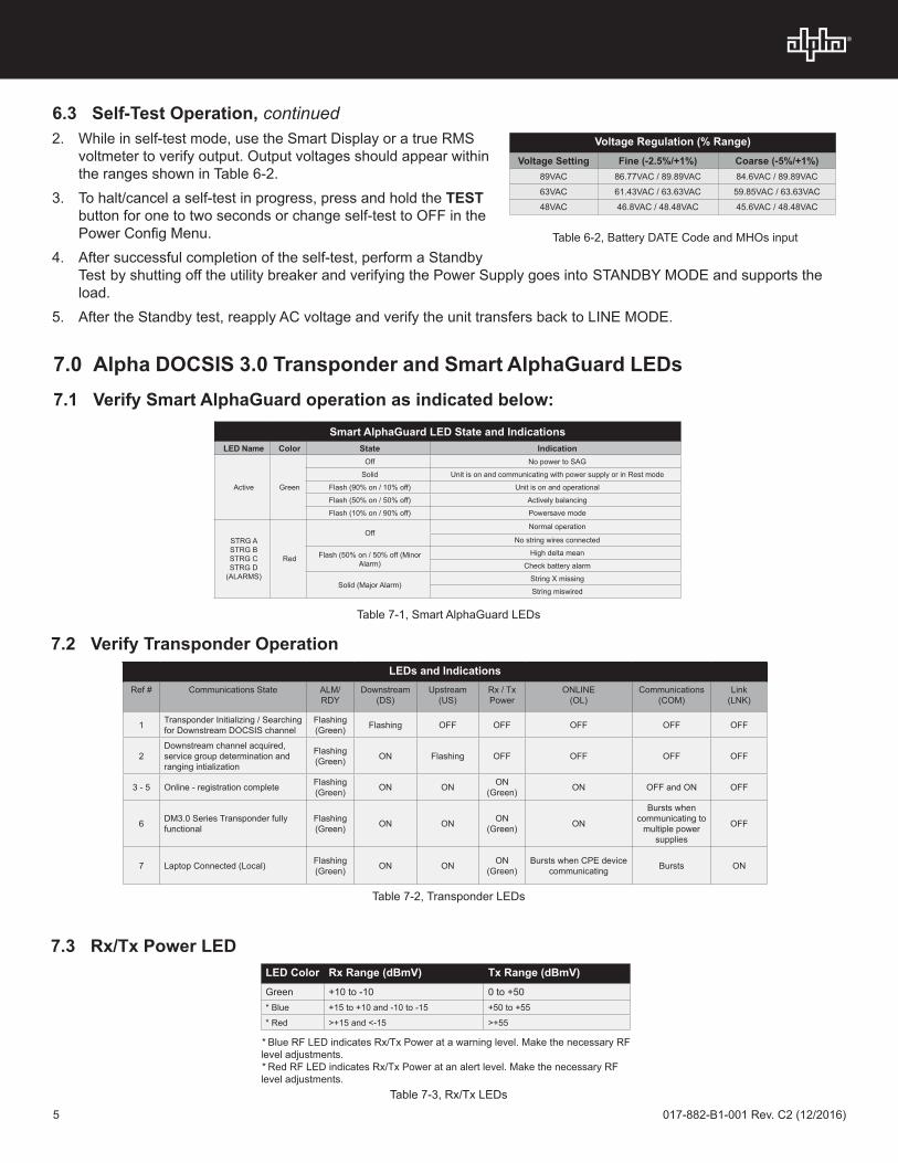
LED Color Rx Range (dBmV) Tx Range (dBmV)Green +10 to -10 0 to +50 * Blue +15 to +10 and -10 to -15 +50 to +55
* Red >+15 and <-15 >+55
7.0 Alpha DOCSIS 3.0 Transponder and Smart AlphaGuard LEDs7.1 Verify Smart AlphaGuard operation as indicated below:
* Blue RF LED indicates Rx/Tx Power at a warning level. Make the necessary RF level adjustments.* Red RF LED indicates Rx/Tx Power at an alert level. Make the necessary RF level adjustments.
Smart AlphaGuard LED State and IndicationsLED Name Color State Indication
Active Green
Off No power to SAG
Solid Unit is on and communicating with power supply or in Rest mode
Flash (90% on / 10% off) Unit is on and operational
Flash (50% on / 50% off) Actively balancing
Flash (10% on / 90% off) Powersave mode
STRG A STRG B STRG C STRG D
(ALARMS)
Red
OffNormal operation
No string wires connected
Flash (50% on / 50% off (Minor Alarm)
High delta mean
Check battery alarm
Solid (Major Alarm)String X missing
String miswired
7.3 Rx/Tx Power LED
7.2 Verify Transponder OperationLEDs and Indications
Ref # Communications State ALM/RDY
Downstream (DS)
Upstream (US)
Rx / Tx Power
ONLINE(OL)
Communications (COM)
Link(LNK)
1 Transponder Initializing / Searching for Downstream DOCSIS channel
Flashing (Green) Flashing OFF OFF OFF OFF OFF
2Downstream channel acquired, service group determination and ranging intialization
Flashing (Green) ON Flashing OFF OFF OFF OFF
3 - 5 Online - registration complete Flashing (Green) ON ON ON
(Green) ON OFF and ON OFF
6 DM3.0 Series Transponder fully functional
Flashing (Green) ON ON ON
(Green) ON
Bursts when communicating to
multiple power supplies
OFF
7 Laptop Connected (Local) Flashing (Green) ON ON ON
(Green)Bursts when CPE device
communicating Bursts ON
Table 7-2, Transponder LEDs
Table 7-3, Rx/Tx LEDs
Table 7-1, Smart AlphaGuard LEDs
2. While in self-test mode, use the Smart Display or a true RMS voltmeter to verify output. Output voltages should appear within the ranges shown in Table 6-2.
3. To halt/cancel a self-test in progress, press and hold the TEST button for one to two seconds or change self-test to OFF in the Power Config Menu.
4. After successful completion of the self-test, perform a Standby Test by shutting off the utility breaker and verifying the Power Supply goes into STANDBY MODE and supports the load.
5. After the Standby test, reapply AC voltage and verify the unit transfers back to LINE MODE.
Voltage Regulation (% Range)Voltage Setting Fine (-2.5%/+1%) Coarse (-5%/+1%)
89VAC 86.77VAC / 89.89VAC 84.6VAC / 89.89VAC
63VAC 61.43VAC / 63.63VAC 59.85VAC / 63.63VAC
48VAC 46.8VAC / 48.48VAC 45.6VAC / 48.48VAC
Table 6-2, Battery DATE Code and MHOs input
6.3 Self-Test Operation, continued
Alpha Technologies Alpha reserves the right to change specifications without notice.Alpha is a registered trademark of Alpha Technologies.
For more information visit www.alpha.com
© 2016 Alpha Technologies Inc. All Rights Reserved.
017-882-B1-001, Rev. C2 (12/2016)
Worldwide Corporate Offices
North AmericaTel: +1 360 647 2360Fax: +1 360 671 4936
EuropeTel: +49 9122 79889 0Fax: +49 9122 79889 21
Latin AmericaTel: +561 792.9651Fax: +561 792.7157
Asia PacificTel: +852 2736.8663Fax: +852 2199.7988
8.0 Final Verification 8.1 Local Web Server AccessThe ethernet port of the Alpha DOCSIS Transponder can be used as a local connection point, allowing the user to connect to the transponder web page. To access the web page, follow the steps below:
1. Using a standard (CAT5) Ethernet cable, connect the transponder to the laptop or computer network interface port.2. Launch a web browser.3. Enter the transponder’s default IP address (192.168.100.1) into the web browser’s address field.4. The transponder’s web server home page will appear.
A Static IP address (192.168.100.2) may need to be set on your network interface card to connect to the transponder.
NOTICE:
For the Alpha DOCSIS Transponder, this may take up to 45 seconds when the transponder is initially powered up with no RF connection.
NOTICE:
8.2 Remote Web Server AccessTo remotely access the Alpha DOCSIS Transponder web server utilizing a web browser:
1. Open a web browser on a computer connected to the same network as the XM3.
2. Enter the Alpha DOCSIS Transponder’s designated IP address (e.g., 192.168.1.124) into the web browser address field.
3. The Alpha DOCSIS Transponder’s web server home page will appear.
Fig. 8-1, Transponder Home Page (sample data only)
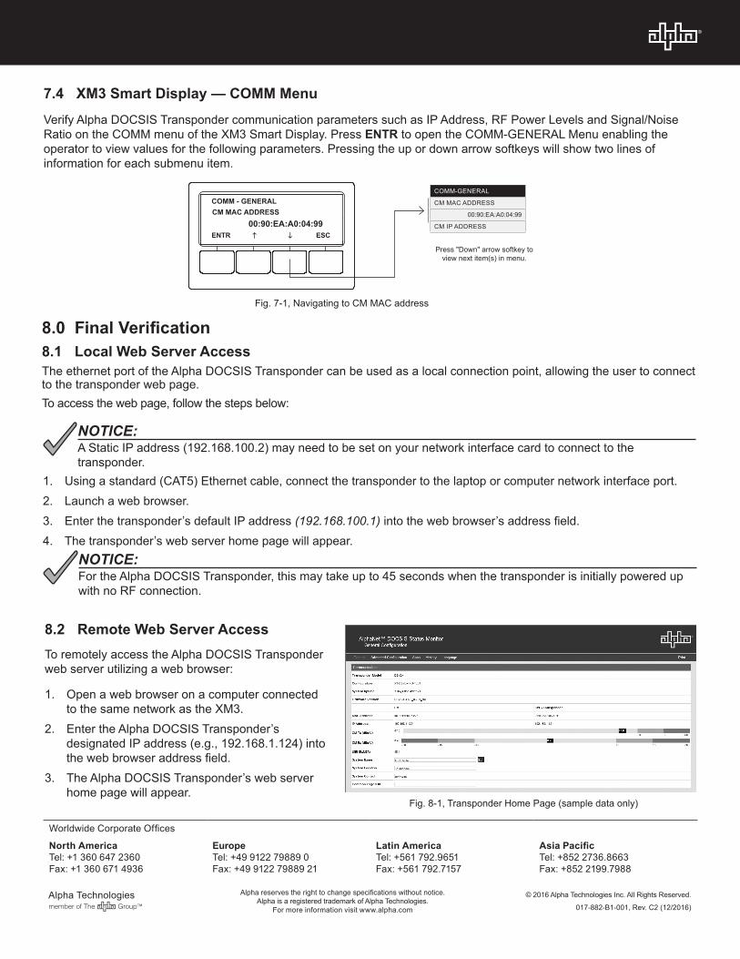
7.4 XM3 Smart Display — COMM MenuVerify Alpha DOCSIS Transponder communication parameters such as IP Address, RF Power Levels and Signal/Noise Ratio on the COMM menu of the XM3 Smart Display. Press ENTR to open the COMM-GENERAL Menu enabling the operator to view values for the following parameters. Pressing the up or down arrow softkeys will show two lines of information for each submenu item.
Press "Down" arrow softkey to view next item(s) in menu.
COMM-GENERAL
CM MAC ADDRESS
00:90:EA:A0:04:99
CM IP ADDRESS
COMM - GENERALCM MAC ADDRESS
00:90:EA:A0:04:99ENTR h i ESC
Fig. 7-1, Navigating to CM MAC address