Embed Size (px)
Citation preview
1745-838-C5-001 Rev. A
PowerAlpha XP-EDH-A2 Transponder Field Installation Instructions
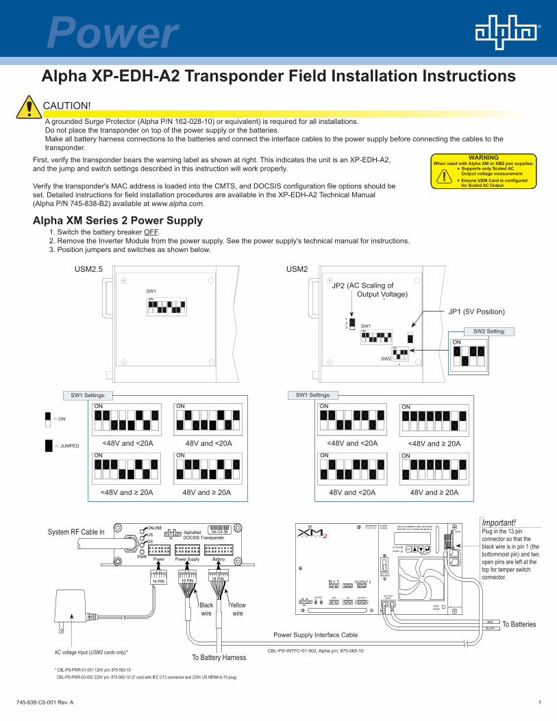
A grounded Surge Protector (Alpha P/N 162-028-10) or equivalent) is required for all installations.Do not place the transponder on top of the power supply or the batteries. Make all battery harness connections to the batteries and connect the interface cables to the power supply before connecting the cables to the transponder.
First, verify the transponder bears the warning label as shown at right. This indicates the unit is an XP-EDH-A2, and the jump and switch settings described in this instruction will work properly.
Verify the transponder's MAC address is loaded into the CMTS, and DOCSIS configuration file options should be set. Detailed instructions for field installation procedures are available in the XP-EDH-A2 Technical Manual (Alpha P/N 745-838-B2) available at www.alpha.com.
Alpha XM Series 2 Power Supply1. Switch the battery breaker OFF. 2. Remove the Inverter Module from the power supply. See the power supply's technical manual for instructions.3. Position jumpers and switches as shown below.
ON
USM2.5
48V and ≥ 20A
ON
48V and <20A
ON
<48V and ≥ 20A
ON
ON
<48V and <20A
ON
JUMPED
ON
ON
123
ON
USM2
ON
48V and ≥ 20A
ON
48V and <20A
<48V and ≥ 20A
ON
<48V and <20A
ON
JP2: 2-3 Jumped
JP1 (5V Position)
SW1
SW1 Settings: SW1 Settings:
SW2 Setting:SW1
SW2
UNLATCH RIBBON CABLE RETAINERBEFORE FULLY REMOVING MODULE.
OUTPUT 1
OUTPUT 2N + 1
SSROUTPUTN L
LRI
WH
T
RE
D
BLA
CK
BATTERY
BLK
INPUT
BREAKERBATTERY
transformerm o d u l e module
inverter
ALARM
OUTPUTESC
M
TEMPPROBE
BLACK
RED
TEST S
SCO
Y
TMPR
Power SupplyPWR Power
14 PIN
USDS
Battery
18 PIN16 PIN
ONLINE
DOCSIS TransponderAlphaNet 0A C4 36System RF Cable in
To Battery Harness
Blackwire
Yellowwire
To Batteries
Important!Plug in the 13 pin connector so that the black wire is in pin 1 (the bottommost pin) and two open pins are left at the top for tamper switch connector.
AC voltage input (USM2 cards only)*
Power Supply Interface Cable
cbl-ps-intfc-01-003, Alpha p/n: 875-565-10
* CBL-PS-PWR-01-001 120V p/n: 875-563-10 CBL-PS-PWR-03-002 220V p/n: 875-562-10 (3' cord with IEC C13 connector and 220V US NEMA 6-15 plug)
CAUTION!
(AC Scaling of Output Voltage)

2745-838-C5-001 Rev. A
Power SupplyPWR Power
14 PIN
USDS
Battery
18 PIN16 PINFuse
WARNING:
3
INDICATORLAMP
REMOTESTATUSRELAY
STANDBY
1 2
OUTPUT
4 65
AC
BLA
CK
RE
D
BATTERYCONNECTOR+
CIRCUITBREAKER
-
BATTERY OFF
BLACK
RED
DOCSIS TransponderAlphaNet 0A C4 36
ONLINESystem RF Cable in
AC Voltage Input120V p/n 875-563-10220V p/n 875-562-10
To Battery Harness
Power Supply Interface Cablep/n 875-565-10
Blackwire
Yellowwire
To Batteries
Jumper PositionP1 2-3P2 openP3 openP4 closedP5 closedP6 closedP7 5VP8 1-2P9 1-2
P13 1-2P14 1-2SW4 0
SW1
DC
123
18 PIN
Battery
Blackwire
Red/Greenwire
ViewSide
CutHere
CUT AND REMOVE A PIECE OFRED/GREEN WIRE IF PRESENT
FOR XM SERIES ONLY
!
CUT THE WIREIN UPPER LEFT POSITIONAS SHOWN. ANY WIRE COLOR.
Remove the USM and set the jumpers as shown below:
120VAC TO
9VACCBL-PS-PWR-01-001Alpha P/N 875-563-10
3 FT CORD
NEMA 6-15P220V US
220VAC
IEC C13
9VACTO
CBL-PS-PWR-03-002Alpha P/N 875-562-10
CBL-PS-INTFC-01-003
CBL-PS-INTFC-01-003Alpha P/N 875-565-10
Or
Necessary Cables
Alpha XM Series Power Supply
Set to 0 (SWs 1,2,3 may not be present on some boards)
Potentiometer Adjuster
RJ Connector
Power Supply Interface
= Jumped
SW2 SW3 SW4
R812
12
12
1
1
1
P1
P2
P3
P4
P5
P6
P75V
24V 15V
P8 P9 P13 P14
ACCUR
AC Volts
123
123
123
USM
3
PIN 1
A
A
B
B
Important!Plug in the 13 pin connector so the black wire is in pin one (the top pin) and two open pins are left at the bottom for tamper switch connection.
NOTE:A chipset upgrade to the XM Inverter Module and/or USM Card may be required; contact Alpha for more information.Set the jumpers and calibrate the USM card before making cable connections and applying load.
1. Switch the battery breaker OFF. 2. Remove the Inverter Module from the power supply. See the power supply's technical manual for instructions.3. Position jumpers and switches as shown below.
First, verify the transponder bears the warning label as shown at right. This indicates the unit is an XP-EDH-A2, and the jump and switch settings described in this instruction will work properly.
NOTE:The EDH-A2 calculates Output Voltage using AC Scaling as opposed to the EDH-A which uses DC Scaling. This requires changes to the USM card jumper settings and eliminates the need to calibrate the USM potentiometer.

3745-838-C5-001 Rev. A
Alpha AM/AP Series Power SupplySwitch the battery breaker OFF.
• The power supply must be disconnected from line voltage during installation.• If not already installed, install an RPM card. Refer to RPM instructions for details.
120VAC TO
9VAC
CBL-PS-PWR-01-001Alpha P/N 875-563-10
3 FT CORD
NEMA 6-15P220V US
220VAC
IEC C13
9VACTO
CBL-PS-PWR-03-002Alpha P/N 875-562-10
OrCBL-PS-INTFC-01-002Alpha P/N 875-564--10
Note:Rev. B of this cable does not have a Violet wire
Necessary Cables
NOTE:
Outer band on DIN connector is black on older ZTT+ models and silver on newer models.
Switch to ZTT Only for ZTT power supplies. Switch to +Silver or +Black for ZTT+ power supplies, depending on whether the outer band on the DIN connector is silver or black.
Lectro ZTT and ZTT+ Power SuppliesSwitch the battery breaker OFF.
ZTTZTT+
ZTT+
SILVER
GROUND
TAMPER
BLACK
CBL-PS-INTFC-02-005
9VAC
120VAC TO
220VAC
NEMA 6-15P220V US
9VAC
3 FT CORD
IEC C13
TO
CBL-PS-INTFC-02-005Alpha P/N 875-566-10
CBLPS-PWR-02-002Alpha P/N 875-718-10
CBLPS-PWR-04-001Alpha P/N 875-717-10
Necessary Cables
or
NOTE:
Maintain correct polarity when making this connection. If reversed, the transponder will be damaged and Vout will not be readable.
Power SupplyPWR Power
110V AC Line Input
14 PIN
ONLINEUSDS
16 PIN
CBL-
PS-IN
TRFC
-01-
001
Battery
CB
L-P
S-B
AT-
04-0
04
18 PIN
DOCSIS TransponderAlphaNetR 0A C4 36
BLACK
RED
C BL-PS- IN TR FC-01-002
Alpha
S E R I E S
Technoligies
AM/AP
1234567
89
10
NOCOM
NC
LAMP
OUTPUT
BATT+- RED
BLACK
0A C4 36DOCSIS TransponderAlphaNet
To Battery Harness
Power Supply Interface Cablep/n 875-566-10
To Batteries
System RF Cable in
Ground
Tamper
Power Output Cable with transformer120V p/n 875-718-10, 220V p/n 875-717-10
To Load
The power supply must be disconnected from line voltage during installation.
Important!Plug in the 13 pin connector so the black wire is in pin one (the right-hand pin) and two open pins are on the left for tamper switch connection. If present, cut the Violet wire (pin 9).
CBL-PS-INTRFC-01-002
HOT
NEUT
CBL-PS-INTFC-01-002Alpha P/N 875-564-10
Alpha Technologies reserves the right to make changes to the products and information contained in this document without notice. Copyright © 2009 Alpha Technologies. All Rights Reserved. Alpha® is a registered trademark of Alpha Technologies. member of The Alpha Group™ is a trademark of Alpha Technologies.745-838-C5-001, Rev. A (07/2009)
For more information visit www.alpha.comUnited States Bellingham, Washington Tel: 360 647 2360 Fax: 360 671 4936Canada Burnaby, British Columbia Tel: 604 430 1476 Fax: 604 430 8908To report errors in this document send email to: [email protected]
member of The GroupTM
4
Total Power Solutions
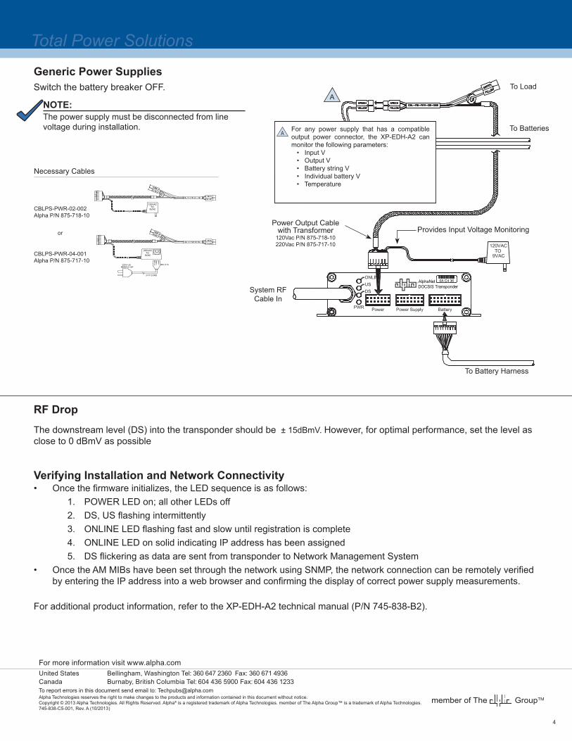
RF Drop
The downstream level (DS) into the transponder should be ± 15dBmV. However, for optimal performance, set the level as close to 0 dBmV as possible
Verifying Installation and Network Connectivity• Once the firmware initializes, the LED sequence is as follows:
1. POWER LED on; all other LEDs off2. DS, US flashing intermittently3. ONLINE LED flashing fast and slow until registration is complete4. ONLINE LED on solid indicating IP address has been assigned5. DS flickering as data are sent from transponder to Network Management System
• Once the AM MIBs have been set through the network using SNMP, the network connection can be remotely verified by entering the IP address into a web browser and confirming the display of correct power supply measurements.
For additional product information, refer to the XP-EDH-A2 technical manual (P/N 745-838-B2).
Generic Power SuppliesSwitch the battery breaker OFF.
9VAC
120VAC TO
220VAC
NEMA 6-15P220V US
9VAC
3 FT CORD
IEC C13
TO
CBLPS-PWR-02-002Alpha P/N 875-718-10
CBLPS-PWR-04-001Alpha P/N 875-717-10
or
Necessary Cables
NOTE:
0A C4 36DOCSIS TransponderAlphaNet
To Load
To BatteriesFor any power supply that has a compatible output power connector, the XP-EDH-A2 can monitor the following parameters: • Input V • Output V • Battery string V • Individual battery V • Temperature
System RF Cable In
To Battery Harness
Provides Input Voltage MonitoringPower Output Cable
with Transformer120Vac P/N 875-718-10220Vac P/N 875-717-10
A
A
The power supply must be disconnected from line voltage during installation.
201310/2013
604 436 5900 604 436 1233

![TRANSPONDER BYPASS: SENTRY KEY [INSTALLATION GUIDE] · Transponder Bypass: RF override via induction w/ loop antenna (transponder incl. no key required). This transponder bypass kit](https://img.pdfslide.us/doc/110x75/5f51bec37e825f53705baf2b/transponder-bypass-sentry-key-installation-guide-transponder-bypass-rf-override.jpg)