Embed Size (px)
Citation preview

Technical ManualModel XP-EDH-A2
Model XP-EDHEffective: October 2009
Alpha Technologies
AlphaNet™ SeriesExternal DOCSIS® Transponder

PowerAlpha Technologies ®

3745-838-B2-001 Rev. A
AlphaNet™ SeriesExternal DOCSIS Transponder
Model XP-EDH-A2Technical Manual
745-838-B2-001, Rev. A
Effective Date: October 2009Copyright © 2009
Alpha Technologies, Inc.
Contacting Alpha Technologies: www.alpha.comor
For general product information and customer service (7 AM to 5 PM, Pacifi c Time), call
1-800-863-3930,
For complete technical support, call
1-800-863-33647 AM to 5 PM, Pacifi c Time or 24/7 emergency support
DOCSIS® is a Registered Trademark of CableLabs.
member of The GroupTM
Alpha denies responsibility for any damage or injury involving its enclosures, power supplies, generators, batteries or other hardware, manufactured by Alpha or members of the Alpha Group, when used for an unintended purpose, installed or operated in an unapproved manner, or improperly maintained.
NOTE:
Photographs and drawings contained in this manual are only for illustrative purposes. These photographs and drawings may not exactly match your installation.
NOTE:
Review the written and illustrative information contained in this manual before proceeding. If there are questions regarding the safe installation or operation of this powering system or enclosure, please contact Alpha Technologies or your nearest Alpha representative.
NOTE:

4 745-838-B2-001 Rev. A
Table of ContentsSafety Notes .......................................................................................................................... 6
1.0 Introduction ................................................................................................................. 7 1.1 System Overview ............................................................................................. 81.2 LED Indicators ................................................................................................. 91.3 MAC Address ................................................................................................... 9
2.0 Installation................................................................................................................. 102.1 General Installation Information for Supported Power Supplies .................... 10
2.1.1 Mounting the Transponder ...................................................................112.1.2 Disconnecting DC Power .....................................................................112.1.3 Confi guring the Interface Card .............................................................112.1.4 Wiring the Battery Harness ..................................................................112.1.5 Connecting the Power Supply Interface and Measurement Cables ... 122.1.6 Confi rming the RF Drop ...................................................................... 122.1.7 Provisioning Network Connectivity ...................................................... 122.1.8 Confi guring AM MIBS .......................................................................... 122.1.9 Setting the DOCSIS Confi guration File Options.................................. 132.1.10 Verifying Operation.............................................................................. 13
3.0 Installation Instructions for Specifi c Power Supplies ................................................ 143.1 Alpha XM2 Series .......................................................................................... 14
3.1.1 USM2.5 Jumper Settings .................................................................... 153.1.2 Output Voltage Calibration .................................................................. 153.1.3 USM2 Jumper Settings ....................................................................... 163.1.4 Output Voltage Calibration .................................................................. 173.1.5 Connecting the XP-EDH-A2 to an XM2 Series Power Supply ............ 183.1.6 Provisioning the Network for the XM2 Series...................................... 19
3.2 Alpha XM Series Power Supply ..................................................................... 203.2.1 XM Series Jumper Settings................................................................. 213.2.2 Output Voltage Calibration .................................................................. 213.2.3 Connecting the XP-EDH-A2 to a XM Series Power Supply ................ 223.2.4 Provisioning the Network for the XM Series........................................ 23
3.3 Alpha AM/AP Series Power Supply ............................................................... 243.3.1 Connecting the XP-EDH-A2 to an AM/AP Series Power Supply ........ 243.3.2 Output Voltage Calibration .................................................................. 263.3.3 Provisioning the Network for the AM/AP Series .................................. 26
5745-838-B2-001 Rev. A
List of Figures and Tables
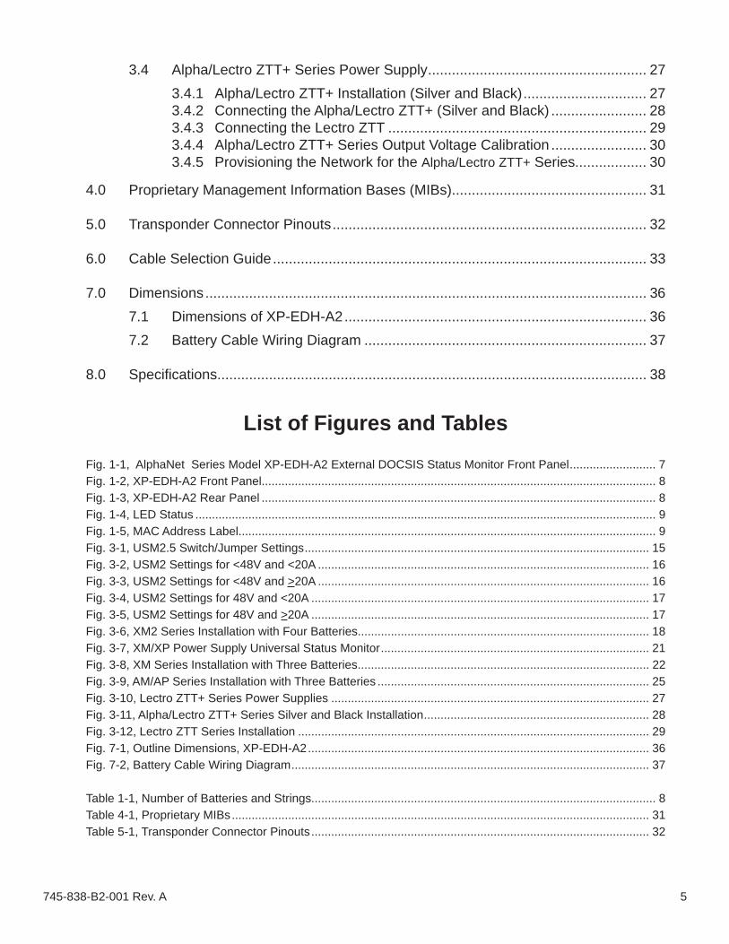
Fig. 1-1, AlphaNet Series Model XP-EDH-A2 External DOCSIS Status Monitor Front Panel .......................... 7Fig. 1-2, XP-EDH-A2 Front Panel....................................................................................................................... 8Fig. 1-3, XP-EDH-A2 Rear Panel ....................................................................................................................... 8Fig. 1-4, LED Status ........................................................................................................................................... 9Fig. 1-5, MAC Address Label.............................................................................................................................. 9Fig. 3-1, USM2.5 Switch/Jumper Settings ........................................................................................................ 15Fig. 3-2, USM2 Settings for <48V and <20A .................................................................................................... 16Fig. 3-3, USM2 Settings for <48V and >20A .................................................................................................... 16Fig. 3-4, USM2 Settings for 48V and <20A ...................................................................................................... 17Fig. 3-5, USM2 Settings for 48V and >20A ...................................................................................................... 17Fig. 3-6, XM2 Series Installation with Four Batteries........................................................................................ 18Fig. 3-7, XM/XP Power Supply Universal Status Monitor ................................................................................. 21Fig. 3-8, XM Series Installation with Three Batteries ........................................................................................ 22Fig. 3-9, AM/AP Series Installation with Three Batteries .................................................................................. 25Fig. 3-10, Lectro ZTT+ Series Power Supplies ................................................................................................ 27Fig. 3-11, Alpha/Lectro ZTT+ Series Silver and Black Installation .................................................................... 28Fig. 3-12, Lectro ZTT Series Installation .......................................................................................................... 29Fig. 7-1, Outline Dimensions, XP-EDH-A2 ....................................................................................................... 36Fig. 7-2, Battery Cable Wiring Diagram ............................................................................................................ 37
Table 1-1, Number of Batteries and Strings........................................................................................................ 8Table 4-1, Proprietary MIBs .............................................................................................................................. 31Table 5-1, Transponder Connector Pinouts ...................................................................................................... 32
3.4 Alpha/Lectro ZTT+ Series Power Supply ....................................................... 273.4.1 Alpha/Lectro ZTT+ Installation (Silver and Black) ............................... 273.4.2 Connecting the Alpha/Lectro ZTT+ (Silver and Black) ........................ 283.4.3 Connecting the Lectro ZTT ................................................................. 293.4.4 Alpha/Lectro ZTT+ Series Output Voltage Calibration ........................ 303.4.5 Provisioning the Network for the Alpha/Lectro ZTT+ Series.................. 30
4.0 Proprietary Management Information Bases (MIBs)................................................. 31
5.0 Transponder Connector Pinouts ............................................................................... 32
6.0 Cable Selection Guide .............................................................................................. 33
7.0 Dimensions ............................................................................................................... 367.1 Dimensions of XP-EDH-A2 ............................................................................ 367.2 Battery Cable Wiring Diagram ....................................................................... 37
8.0 Specifi cations............................................................................................................ 38

6 745-838-B2-001 Rev. A
Safety NotesReview the drawings and illustrations contained in this manual before proceeding. If there are any questions regarding the safe installation or operation of the system, contact Alpha Technologies or the nearest Alpha representative. Save this document for future reference.To reduce the risk of injury or death and to ensure the continued safe operation of this product, the following symbols have been placed throughout this manual. Where these symbols appear, use extra care and attention.
WARNING presents safety information to PREVENT INJURY OR DEATH to the technician or user.
The use of CAUTION indicates safety information intended to PREVENT DAMAGE to material or equipment.
The use of ATTENTION indicates specifi c regulatory/code requirements that may affect the placement of equipment and /or installation procedures.
A NOTE provides additional information to help complete a specifi c task or procedure.
ATTENTION:
NOTE:
CAUTION!
WARNING!

7745-838-B2-001 Rev. A
1.0 IntroductionThe AlphaNet™ Series Model XP-EDH-A2 External DOCSIS Transponder manages network powering through the existing cable modem infrastructure. A single transponder can monitor and manage one power supply and batteries. The transponder transmits data to a management system over the network’s existing infrastructure. Standard SNMP (Simple Network Management Protocol) provides access by any SNMP manager. Status Monitoring information is compatible with ANSI/SCTE HMS standards.The AlphaNet Series transponder provides the tools needed to manage today’s network power requirements, and the ability to upgrade for tomorrow’s needs.
Features: DOCSIS 2.0 certifi ed• Compatible with ANSI/SCTE HMS standards • Single transponder supports a variety of power supply models: XM2, XM, AM, ZTT series• Embedded Web server for remote diagnostics• USB Port enables on-site technician access•
Fig. 1-1, Front panel, AlphaNet Series Model XP-EDH-A2, External DOCSIS Transponder
™

8 745-838-B2-001 Rev. A
1.0 Introduction, continued
1.1 System OverviewThe XP-EDH-A2 is designed for use with the following standby power supplies:
• XM2 • AM/AP• XM • ZTT, ZTT+
The transponder hardware is the same for all applications and harness kits are available for specifi c confi gurations.
The XP-EDH-A2 receives data from a Universal Status Monitoring Card on XM/XM2 series power supplies, from the status monitor connector on Lectro ZTT power supplies, or from the RPM card on AM power supplies. The transponder and power supply can be network managed through your existing CMTS.
To CMTS
Status LEDs
(Optional) Voltage In, Voltage Out, Current Out Sense Kits
USB Port for local diagnostics
Number of Batteries (Voltage) Number of Strings
2 (24Vdc) 1
3 (36Vdc) 1
6 (36Vdc) 2
9 (36Vdc) 3
4 (48Vdc) 1
8 (48Vdc) 2
12 (48Vdc) 3
Table 1-1, Number of Batteries and Strings
Fig. 1-2, XP-EDH-A2 Front Panel
Fig. 1-3, XP-EDH-A2 Rear Panel
1
2 3 4 5
6
7
1
2
3
4
5
6
7Power Supply Connection
Battery String Connection
The complete MAC address will have an Organizational Unique Identifi er – OUI (e.g., 00-03-08) in front of the MAC Address shown on this label.

9745-838-B2-001 Rev. A
1.0 Introduction, continued
1.2 LED IndicatorsThe front panel has four LEDs which indicate the following:
Fig. 1-4, LED Status
1.3 MAC AddressEach transponder is assigned a unique Media Access Control (MAC) address, which is used to communicate with the network. The fi rst 6 digits of the MAC address (the Organizational Unique Identifer (OUI)) for the transponder is 00-03-08. The complete address is located on the label on the top of the device and in this example is 00 03 08 0B 10 F7 27.
MAC address
Fig. 1-5, MAC Address Label
POWER: Indicates device has powerOFF: No powerON: Power on. (Battery harness connected to a battery string)
ONLINE: Indicates a two-way RF (radio frequency) connection.OFF: No communicationFlickering ON: Scanning for CMTS connectionON: Ongoing communication online with CMTS
US (Upstream activity): Indicates data being transferred to the transponder
Flashing ON and OFF: Normal operationOFF: No power or malfunctioning transponder
DS (Downstream activity): Indicates data being transferred from the transponderFlashing ON and OFF: Normal operation
OFF: No power or malfunctioning transponder

10 745-838-B2-001 Rev. A
2.0 InstallationBefore installing the XP-EDH-A2 into a power supply, review your system requirements and determine the number of cable assemblies you need to monitor your HFC standby power supplies.
The procedure for installing the XP-EDH-A2 into any supported power supply involves general information, (information that is common to all the power supplies), and information specifi c to an individual type of power supply. These installation instructions are divided into two sections to refl ect this. It is recommended that you read through the general instructions and then take note of any information specifi c to your power supply.
Also, installation of this product involves both fi eld installation and the confi guration of the system, including network security, SNMP set-up, and other system provisioning. While those two procedures are handled independently, they are presented together in the section specifi c to your power supply.
2.1 General Installation Information for Supported Power Supplies
NOTE:
There are a few basic steps to follow to install the XP-EDH-A2 into supported power supply sites. The steps are either fi eld steps or system confi guration steps, and can be performed independently.
Field installation steps are:
Transponder Placement1.
Disconnecting the DC power2.
Confi guring the Interface Card3.
Wiring the battery harness4.
Connecting the power supply interface and measurement cables5.
Confi rming the RF drop6.
System confi guration steps are:
Provisioning Network Connectivity7.
Confi guring the MIBS8.
Setting the DOCSIS confi guration fi le options9.
Completing and Testing the installation:
Verifying the operation10.
Detailed information on each of these steps follows.
Note the following:The types and quantities of each power supply type• Number of individual batteries per site (if you plan to increase the number of batteries in the • future, consider ordering additional battery harnesses)Length of required battery harness (The standard 4 ft length battery harness is used in the typical • power supply cabinet where one to three battery strings are mounted in the trays underneath the power supply shelf. If necessary, a 20 ft battery harness is available)The required type of interface cards (RPM, USM, USM2.5, etc.)• Utility power available at the site, 110V or 220V.•

11745-838-B2-001 Rev. A
2.0 Installation, continued
2.1 General Installation Information for Supported Power Supplies, continued
2.1.1 Transponder PlacementPlace the transponder on the shelf inside the cabinet next to the power supply. • Do not place the transponder on top of the power supply.Maintain access to the front of the transponder to ease the connection of the • cables.Ensure the cabinet door can close without damaging the cables.• Route and tie-wrap the cables in an orderly manner.•
2.1.3 Confi guring the Interface Card
Each power supply contains an interface card which provides the common communication layer between the power supply and the transponder. The settings needed for your power supply are located in Section 3.0, "Installation Instructions for Specifi c Power Supplies".
2.1.4 Wiring the Battery Harness
2.1.2 Disconnecting the DC Power
Place the DC breaker in the OFF position.
CAUTION!
Backup capability is suspended with the DC breaker in the OFF position.
Prior to connecting the cables to the transponder, make all harness connections • to the batteries and interface connectors on the power supply. See the battery diagrams for your specifi c power supply.Double-check all connections. Incorrect connections may damage the • transponder or the power supply. Correct connections at the batteries are extremely important to the proper operation of the power supply. Ensure that the high current carrying cables and jumpers (heavy gauge black • and red cables) remain in direct contact to the battery terminals.Never place the transponder battery harness lugs between the current carrying • jumper/cable lugs and the battery terminals. See the power supply installation manual for more information.In some cases there are more battery harness leads than there are batteries. • Connect all unused lugs to the same terminal as the V(-) lead, the same terminal where the heavy gauge black cable from the inverter is connected. This prevents stray voltages from being detected by the transponder.
CAUTION!
Incorrect connections may damage the equipment and invalidate the warranty. Double-check all connections.
NOTE:Depending on the type of enclosure and the power supply you are using, it may be necessary to orient the Service Power Inserter (SPI) vertically to provide space for the transponder. Re-torque the SPI to spec (130 in/lbs) if repositioning becomes necessary. This is important, as the output neutral is not tied to ground until connected to the SPI /enclosure.

12 745-838-B2-001 Rev. A
2.1.6 Confi rming the RF Drop
An RF drop is required at the power supply site. The RF drop should not have • plant voltage.
The transponder contains a DOCSIS 2.0 cable modem. The downstream level • (DS) into the transponder should be between -15 and +15 dBmV, with a recom-mended level of 0dBmV.
2.1.7 Provisioning Network Connectivity
The transponder’s cable modem must be recognized by the CMTS as a valid device, obtain an IP address from the DHCP server, locate the TFTP and TOD servers, and communicate with the SNMP management server (trap receiver). Different security methods are used to insure network integrity, some common issues are:
A “subscriber account” (where the subscriber is the transponder) may be required • for each transponder.The transponder’s MAC address may have to be pre-loaded into the CMTS.• MAC fi ltering may have to be modifi ed to allow MAC addresses starting with • 00:03:08xx:xx:xx to be registered.For SNMP access, UDP ports 161 & 162 must not be blocked.• Firewalls must allow communication between the cable modem and the various • servers noted above.If the address of the TFTP and/or TOD server is different than the DHCP server, • the response from the DHCP server must contain the TFTP and TOD addresses.
2.0 Installation, continued
2.1 General Installation Information for Supported Power Supplies, continued
2.1.5 Connecting the Power Supply Interface and Measurement CablesConnect the power supply interface and measurement cables to the power • supply. Connections are dependent on the type of power supply confi guration you are using. See the section specifi c to your confi guration.It is important to be able to measure the site input line voltage. If you are • not using a USM2.5/XM2 power supply, then it is recommended you use a transformer (110V and 220V available*) to sample the commercial power at the site. While it does not power the transponder, it makes it possible for the transponder to report the actual line voltage. An additional transformer is not necessary when using a USM2.5/XM2 power supply.Use a surge protector within the cabinet when you are using a transformer to • measure line voltage. Most cabinets come equipped with a duplex outlet.* 110V applications: CBL-PS-PWR-01-001, p/n 875-563-10
220V applications: CBL-PS-PWR-03-002, p/n 875-562-10(3' cord with IEC C13 connector and 220V US NEMA 6-15 plug)
2.1.8 Confi guring MIBsThis step is not performed in the fi eld, but at the network end of the installation. • There are two propriety MIBs (Management Information Base) from Networks • needed to confi gure the XP-EDH-A2. Refer to Section 4.0, "Proprietary Management Information Bases (MIBs)" for detailed information.

13745-838-B2-001 Rev. A
2.1.10 Verifying OperationAfter the connections are complete and the transponder’s online LED is on solid, • indicating network connectivity, verify the site is visible on the appropriate cable modem or computer network, and that all parameters being monitored are visible and accurate.Any standard Web browser on a personal computer confi gured for network • connectivity to the transponder should be able to read the XP-EDH-A2 Web interface by simply pointing the Web browser to the IP address of the transponder (for example, http://10.1.3.65).Confi rm that all cable harnesses are neatly dressed within the enclosure.• Verify that you can close the cabinet door, and move the battery tray in and out, • without contacting or damaging any of the cables.
Sets Read-Write Community string. Set the IP addresses and community strings to fi t your system.
Sets Read-Only Community string. Set the IP addresses and community strings to fi t your system.
Sets fi rmware download parameters.
Sets Code Verifi cation Certifi cate (CVC)
SNMP MIB Object (11) [Len=21]:docsDevNmAccessStatus.1/4SNMP MIB Object (11) [Len=21]:docsDevNmAccesslp.1/192.168.1.0SNMP MIB Object (11) [Len=21]:docsDevNmAccesslpMask.1/255.255.255.0SNMP MIB Object (11) [Len=25]:docsDevNmAccessCommunity.1/"RWRWRWRW"SNMP MIB Object (11) [Len=21]:docsDevNmAccessControl.1/3
SNMP MIB Object (11) [Len=21]:docsDevNmAccessStatus.2/4SNMP MIB Object (11) [Len=21]:docsDevNmAccesslp.2/192.168.1.0SNMP MIB Object (11) [Len=21]:docsDevNmAccesslpMask.2/255.255.255.0SNMP MIB Object (11) [Len=25]:docsDevNmAccessCommunity.2/"RORORORO"SNMP MIB Object (11) [Len=21]:docsDevNmAccessControl.2/2
Software Upgrade Filename(9) [Len=24]:"MODEM_Firmware_file.bin”SNMP MIB Object (11) [Len=20]:docsDevSwAdminStatus.0/2Software Upgrade TFTP Server (21) [Len=4]:192.168.1.51
Manufacturer Code Verification Certificate (32) [Len=254]: 30 82 03 1A 30 82...Manufacturer Code Verification Certificate (32) [Len=254]: 04 0A 13 11 41 4D...Manufacturer Code Verification Certificate (32) [Len=254]: 04 0C 30 0A 06 01...Manufacturer Code Verification Certificate (32) [Len=36]: 11 A3 41 A6 A7 D9....
2.0 Installation, continued
2.1 General Installation Information for Supported Power Supplies, continued
2.1.9 Setting the DOCSIS Confi guration File OptionsThis step is performed at the network end of the installation. • This fi le supplies the security and community string settings for the system, as • well as the software upgrade parameters. Set the community strings, matching your DOCSIS cable modems. The following is an example:

14 745-838-B2-001 Rev. A
3.0 Installation Instructions for Specifi c Power SuppliesThese are specifi c installation instructions for standby power supplies supported by the XP-EDH-A2 transponder. Each set of instructions include the interface card settings, a system diagram, and the output voltage calibration needed to successfully operate.
NOTE:All settings and instructions specifi ed here supercede information found in previous manuals.
3.1 Alpha XM2 Series
ATTENTION: Alpha's XM2 power supply installations using USM2 (both new and old versions) and USM2.5 cards require switch/jumper settings to be made for proper operation.
1. Determine the characteristics of the power supply, such as the inverter voltage (36V or 48V), and the maximum capable output current (typically <20A or >20A).
2. If commercial power is present at the site and the power supply is currently being powered by commercial AC line voltage, turn the battery breaker OFF on the inverter module.
NOTE:When monitoring commercial line power, the XM2 (with the USM2.5 card) does not require an input voltage transformer because the USM2.5 card provides a scaled voltage representing the line input to the power supply. In this situation, the transponder makes the measurement via the interface cable connected to the USM2.5 card.
3. Slide the inverter drawer out to gain access to the switches or jumpers located on the various types of USM2 and USM2.5 cards. If you need to install a USMx card, refer to the manual supplied with the card and complete the installation process.
4. Refer to the following diagram and adjust the switch settings to match your power supply.
5. Re-insert the inverter module and tighten the retaining screws.
NOTE:Turning the battery breaker OFF disables standby power.
NOTE:The EDH-A2 supports AC Scaling for Output Voltage measurements as opposed to DC scaling for the EDH-A. As a result the USM2/USM2.5 switch settings are different and calibration is no longer necessary. Refer to the EDH-A Installation Manual for EDH-A installation procedures.

15745-838-B2-001 Rev. A
3.1.1 USM2.5 Jumper Settings
Fig. 3-1, USM2.5 Switch/Jumper Settings
FRONT PANEL
POWER SUPPLYCHASSIS
ON
SW1
48V and > 20A
ON
48V and <20A
ON
<48V and > 20A
ON
ON
<48V and <20A
ON
SW1 Settings:
Legend:
3.0 Installation Instructions for Specifi c Power Supplies, continued
3.1 Alpha XM2 Series, continued
NOTE:The switch settings in this section apply only to the EDH-A2 and differ from the EDH-A. Refer to the EDH-A Installation Manual for EDH-A installation procedures.
3.1.2 Output Voltage Calibration
EDH-A2 supports AC Scaling for Output Voltage measurements and does not require USM2.5 potentiometer calibration.
16 745-838-B2-001 Rev. A
3.0 Installation Instructions for Specifi c Power Supplies, continued
3.1 Alpha XM2 Series, continued
ON
ON
123
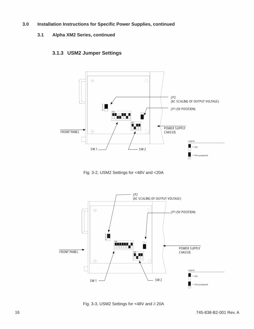
Fig. 3-2, USM2 Settings for <48V and <20A
3.1.3 USM2 Jumper Settings
Fig. 3-3, USM2 Settings for <48V and > 20A
ON
ON
123
FRONT PANELPOWER SUPPLYCHASSIS
FRONT PANELPOWER SUPPLYCHASSIS
JP2 (AC SCALING OF OUTPUT VOLTAGE)
JP1 (5V POSITION)
SW 1 SW 2
JP2 (AC SCALING OF OUTPUT VOLTAGE)
JP1 (5V POSITION)
SW 1 SW 2ON
Legend:
Pins jumpered
ON
Legend:
Pins jumpered

17745-838-B2-001 Rev. A
3.0 Installation Instructions for Specifi c Power Supplies, continued
3.1 Alpha XM2 Series, continued
ON
ON
123
Fig. 3-5, USM2 Settings for 48V and > 20A
ON
ON
123
Fig. 3-4, USM2 Settings for 48V and <20A
3.1.3 USM2 Jumper Settings, continued
FRONT PANELPOWER SUPPLYCHASSIS
FRONT PANELPOWER SUPPLYCHASSIS
JP2 (AC SCALING OF OUTPUT VOLTAGE)
JP1 (5V POSITION)
SW 1 SW 2
JP2 (AC SCALING OF OUTPUT VOLTAGE)
JP1 (5V POSITION)
SW 1 SW 2
ON
Legend:
Pins jumpered
ON
Legend:
Pins jumpered
NOTE:The switch settings in this section apply only to the EDH-A2 and differ from the EDH-A. Refer to the EDH-A Installation Manual for EDH-A installation procedures.
3.1.4 Output Voltage Calibration
EDH-A2 supports AC Scaling for Output Voltage measurements and does not require USM2.5 potentiometer calibration.
18 745-838-B2-001 Rev. A
3.0 Installation Instructions for Specifi c Power Supplies, continued
3.1 Alpha XM2 Series, continued
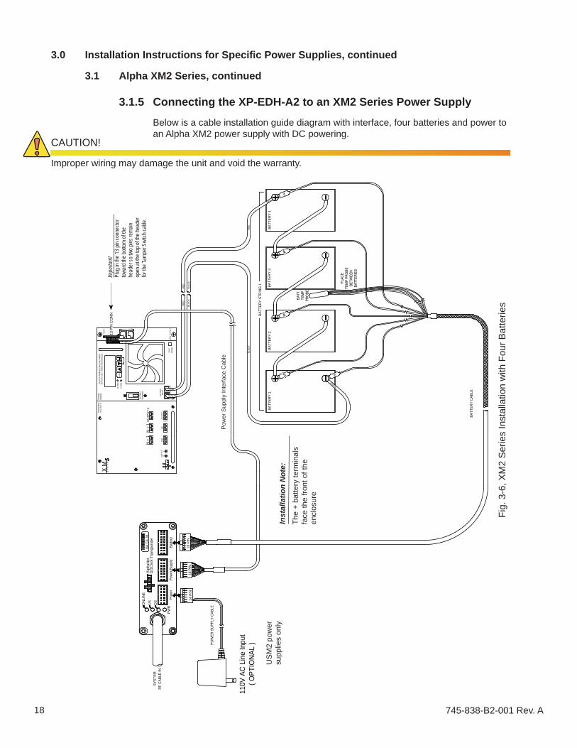
3.1.5 Connecting the XP-EDH-A2 to an XM2 Series Power Supply
Below is a cable installation guide diagram with interface, four batteries and power to an Alpha XM2 power supply with DC powering.
Fig.
3-6
, XM
2 S
erie
s In
stal
latio
n w
ith F
our B
atte
ries
UN
LATC
H R
IBBO
N C
ABLE
RET
AINE
RBE
FOR
E FU
LLY
REM
OVI
NG M
ODU
LE.
OU
TPU
T 1
OU
TPU
T 2
N +
1
SSR
OU
TPUT
NL
LRI
WHT
RED
BLACKBATT
ERY
BLK
INPU
T
BREA
KER
BATT
ERY
X M
S
E R
I E
S
trans
form
erm
o d
u l
em
odul
ein
verte
r
ALAR
M
OU
TPUT
ESC
M
TEM
PPR
OBE
RED
BLAC
KBL
ACK
RED
TEST
13 P
IN C
ONN
S S C OY
TMPR
Powe
r Sup
ply
PWR
Powe
r
110V
AC
Line
Inpu
t
POW
ER S
UPPL
Y CA
BLE
14 P
IN
RF C
ABLE
INSY
STEM
US DS
Batte
ry
18 P
IN16
PIN
BATT
ERY
CABL
E
PLAC
ETE
MP
PRO
BE
BET
WEE
NB
ATTE
RIE
S
BLACK
BATT
ERY
1
BAT
TTE
MP
PRO
BE
-V
BATT
ERY
2
+12V
BLAC
K
+24V
+V
BATT
ERY
3
+36V
BATT
ERY
4
RED
RED
BATT
ERY
STRI
NG 1
( OPT
IONA
L )
ONL
INE
DOCS
IS T
rans
pond
erAl
phaN
etR
0A C
4 36
N +
1 Pow
er S
uppl
y In
terfa
ce C
able
US
M2
pow
er
supp
lies
only
CAUTION!
Improper wiring may damage the unit and void the warranty.
Inst
alla
tion
Not
e:Th
e +
batte
ry te
rmin
als
face
the
front
of t
he
encl
osur
e
Impo
rtant
!Pl
ug in
the 1
3 pin
conn
ector
tow
ard t
he bo
ttom
of the
he
ader
so tw
o pins
rema
in op
en at
the t
op of
the h
eade
r for
the T
ampe
r Swi
tch ca
ble.

19745-838-B2-001 Rev. A
3.0 Installation Instructions for Specifi c Power Supplies, continued
3.1 Alpha XM2 Series, continued
3.1.6 Provisioning the Network for the XM2 Series
The transponder must be recognized by the CMTS as a valid device, be able to obtain an IP address and communicate with the SNMP management server.
Load the transponder’s MAC address into the CMTS.1.
Compile the two MIBs using a network manager or MIB browser software.2.
Setup SNMP using two proprietary MIBs fi les.3.
Set the MIBS points for the XM2 as follows:4.
For XM2Oid: 1.3.6.1.4.1.2183.2.3.3.1.2 set to (2) (power supply selection)Oid: 1.3.6.1.4.1.2183.2.3.6.5 set to (4) (output voltage scaling)Oid: 1.3.6.1.4.1.2183.2.3.6.6 set to (1)for 110V powered supply or (2) for 220V
Install and confi gure the DOCSIS confi guration fi le. See Section 2.1.9 for a 5. sample fi le.Refer to Section 4.0, "Proprietary Management Information Bases (MIBs)" for detailed information.

20 745-838-B2-001 Rev. A
If commercial power is present at the site, and the power supply is currently being 1. powered by commercial AC line voltage, turn the battery breaker OFF on the inverter module.
3.0 Installation Instructions for Specifi c Power Supplies, continued
3.2 Alpha XM Series Power SupplyNOTE:
You may require a chipset upgrade for the USM and XM inverter drawer for proper operation with the XP-EDH-A2. Operating an XM series power supply with the XP-EDH-A2 with the wrong version chipset fi rmware may result in intermittent or incorrect operation of the power supply. Contact your Alpha representative for additional information.
Slide the inverter drawer out to gain access to the USM card. Remove the USM/APM 2. assembly from the inverter drawer. To install the USM and APM cards, refer to the manual supplied with the cards and complete the installation process.
Refer to the following diagram and adjust the jumper settings to match your power supply.3.
Reinstall the USM/APM assembly into the connector on the inverter drawer. Secure with 4. the screw and bracket.
Re-insert the inverter module.5.
NOTE:When the battery breaker is turned OFF, standby power is disabled.
NOTE:The EDH-A2 supports AC Scaling for Output Voltage measurements as opposed to DC scaling for the EDH-A. As a result the USM switch settings are different and calibration is no longer necessary. Refer to the EDH-A Installation Manual for EDH-A installation procedures.

21745-838-B2-001 Rev. A
3.2.1 XM Series Jumper Settings
Fig. 3-7, XM/XP Power Supply Universal Status Monitor(as viewed from rear of power supply with main control module partially removed)
Jumper PositionP1 2-3P2 openP3 openP4 closedP5 closedP6 closedP7 5VP8 1-2P9 1-2P13 1-2P14 1-2SW4 0
SW1
DC
123
Remove the USM and set the jumpers as follow:
Set to 0 (SWs 1,2,3 may not be present on some boards)
Potentiometer Adjuster
RJ Connector
Power Supply Interface
SW2 SW3 SW4
R812
12
12
1
1
1
P1
P2
P3
P4
P5
P6
P75V
24V 15V
P8 P9 P13 P14
ACCUR
AC Volts
123
123
123
USM
3
PIN 1
Legend:
Pins jumpered
3.0 Installation Instructions for Specifi c Power Supplies, continued
3.2 Alpha XM Series Power Supply, continued
NOTE:The switch settings in this section apply only to the EDH-A2 and differ from the EDH-A. Refer to the EDH-A Installation Manual for EDH-A installation procedures.
3.2.2 Output Voltage Calibration
EDH-A2 supports AC Scaling for Output Voltage measurements and does not require USM2.5 potentiometer calibration.

22 745-838-B2-001 Rev. A
3.0 Installation Instructions for Specifi c Power Supplies, continued
3.2 Alpha XM Series Power Supply, continued
3.2.3 Connecting the XP-EDH-A2 to an XM Series Power Supply
Follow the diagram below to make all connections between the transponder and the power supply site. The diagram is the cable installation guide drawing with interface, three batteries, and power to an Alpha XM power supply.
RED
BLAC
K
POW
ER S
UPPL
Y IN
TERF
ACE
Pow
er S
uppl
yPW
RPo
wer
110V
AC
Lin
e In
put
POW
ER S
UPPL
Y CA
BLE
14 P
IN
RF
CABL
E IN
SYST
EM
US DS
Batte
ry
18 P
IN16
PIN
CBL
-PS-
BAT-
04-0
04 (4
FT
LON
G)
BATT
ERY
CAB
LE
PLA
CE
TEM
P P
ROBE
BET
WE
ENB
ATTE
RIES
BLACK
BATT
ERY
1
BA
TTTE
MP
PRO
BE
-V
BATT
ERY
2
+12V
BLAC
K
+24V
BATT
ERY
3
+VRED
+36V
BATT
ERY
STR
ING
1
Fuse
WAR
NING
:
3
IND
ICAT
ORLA
MP
REM
OTE
STAT
USR
ELAY
STAN
DBY
12
OUT
PUT
46
5AC
BLACK
REDBAT
TERY
CO
NNE
CTO
R+
CIR
CUIT
BRE
AKER -
BAT
TERY
OFF
Alph
a
S E
R I
E S
Tec h
nol ig
ies
X M
BLAC
K
RED
WIR
EYE
LLO
W
18 P
IN
Batte
ry
Blac
kw
ireR
ed/G
reen
wire
View
Side
Cut
Her
e
CU
T AN
D R
EMO
VE A
PIE
CE O
FR
ED/G
REE
N W
IRE
IF P
RESE
NT
FOR
XM S
ERIE
S O
NLY
!CUT
THE
WIR
EIN
UPP
ER L
EFT
POSI
TIO
NAS
SH
OW
N. A
NY
WIR
E CO
LOR.
DO
CSI
S Tr
ansp
onde
rAl
phaN
et0A
C4
36O
NLIN
E
Fig. 3-8, XM Series Installation with Three Batteries
CAUTION!
Improper wiring may damage the unit and void the warranty.
Inst
alla
tion
Not
e:Th
e +
batte
ry te
rmin
als
face
the
front
of t
he
encl
osur
e
Impo
rtant
!Pl
ug in
the 1
3 pin
conn
ector
so
the b
lack w
ire is
in pi
n one
(th
e top
pin)
and t
wo op
en
pins a
re le
ft at th
e bott
om fo
r tam
per s
witch
conn
ectio
n.

23745-838-B2-001 Rev. A
3.0 Installation Instructions for Specifi c Power Supplies, continued
3.2 Alpha XM Series Power Supply, continued
3.2.4 Provisioning the Network for the XM Series
The transponder must be recognized by the CMTS as a valid device, obtain an IP address, and communicate with the SNMP management server.
Load the transponder’s MAC address into the CMTS.1.
Setup SNMP using two proprietary MIBs fi les.2.
Compile the two MIBs onto a network manager or MIB browser software.3.
Set the MIBS points for the XM as follows:4.
Oid: 1.3.6.1.4.1.2183.2.3.3.1.2 set to (3) (power supply selection)Oid: 1.3.6.1.4.1.2183.2.3.6.5 set to (4) (output voltage scaling)Oid: 1.3.6.1.4.1.2183.2.3.6.6 set to (1)for 110V powered supply or (2) for 220V (input voltage measurement)
Install and confi gure the DOCSIS confi guration fi le. See Section 2.1.9 for a 5. sample fi le.
See Section 4.0, Proprietary Management Information Bases (MIBs) for detailed information.

24 745-838-B2-001 Rev. A
3.0 Installation Instructions for Specifi c Power Supplies, continued
3.3 Alpha AM/AP Series Power Supply
If commercial power is present at the site, and the power supply is currently powered 1. by commercial AC line voltage, turn the battery breaker OFF on the power supply and disconnect the power supply from utility power.
If not already installed, install the RPM card. Refer to the instructions that come with this 2. assembly.
WARNING!
Installing the XP-EDH-A2 transponder at an Alpha AM power supply site requires shutting down the power supply. If a short power interruption is not feasible, you must use an alternate source of system power during the installation of the transponder. This is necessary to install the RPM interface card, and to make connections to the output of the power supply to permit monitoring of the output voltage of the power supply.
If a short power interruption is not feasible, you must use an alternate source of system power during the installation of the transponder.
3.3.1 Connecting the XP-EDH-A2 to an AM/AP Series
Follow Fig. 3-9 to make connections between the transponder, the power supply site and battery string.
NOTE:The RPM card cannot be installed while the power supply is running on utility or battery power.

25745-838-B2-001 Rev. A
3.0 Installation Instructions for Specifi c Power Supplies, continued
3.3 Alpha AM/AP Series Power Supply, continued
3.3.1 Connecting the XP-EDH-A2 to a AM/AP Series, continued
POW
ER S
UPP
LY IN
TER
FAC
E
Pow
er S
uppl
yPW
RPo
wer
110V
AC
Lin
e In
put
POW
ER S
UPP
LY C
ABLE
14 P
IN
RF
CAB
LE IN
SYST
EM
ON
LIN
EU
SD
S
16 P
IN CBL-PS-INTRFC-01-001
Batte
ry
CBL-PS-BAT-04-004
18 P
IN
BLAC
K
LAR
GER
PAR
TIAL
VIE
W
DO
CSI
S Tr
ansp
onde
rAl
phaN
etR
0A C
4 36
BLAC
K
RED
+ -
4 3 28 7 610C
OM
+NO
BLAC
K
NC
RED
BLAC
K
AM/A
PS
E R
I E
S
PIN
1BL
ACK
WIR
E
+12V
BATT
ERY
STR
ING
1 +24V
BAT
TTE
MP
PRO
BE
PLAC
ETE
MP
PRO
BE
BE
TWE
ENB
ATTE
RIE
S
BATT
ERY
3R
ED
+V
BLAC
K
RED
Tech
nolig
iesAl
pha
RED
-BA
TT1O
UTP
UT
LAM
P
9 5
BATT
ERY
CAB
LE
POW
ER S
UPP
LY IN
TER
FAC
E
CBL-PS-INTRFC-01-002
Alph
a
S E
R I
E S
Tech
nolig
ies AM/A
PTO
BA
TTER
IES
BLAC
K
RED
12345678910
WAR
NIN
G:
NO
CO
M
NC
LAM
P
OU
TPU
T
BATT+ -
RED
BLAC
K
BATT
ERY
1
BLAC
K
BATT
ERY
2
+36V
BLACK
-V
RED
Fig. 3-9, AM/AP Series Power Supply, Transponder with Three Batteries
CAUTION!
Improper wiring may damage the unit and void the warranty.
Inst
alla
tion
Not
e:Th
e +
batte
ry te
rmin
als
face
the
front
of t
he
encl
osur
e
Impo
rtant
!Pl
ug in
the 1
3 pin
conn
ector
to
the rig
ht as
show
n so t
he
two o
pen p
ins fo
r the
tamp
er
switc
h con
necto
r are
to th
e lef
t. If p
rese
nt, cu
t the V
iolet
wi
re.

26 745-838-B2-001 Rev. A
3.0 Installation Instructions for Specifi c Power Supplies, continued
3.3 Alpha AM/AP Series Power Supply, continued
3.3.2 Output Voltage Calibration
No calibration is necessary for the Alpha AM/AP power supply.
3.3.3. Provisioning the Transponder on the Network
The transponder must be recognized by the CMTS as a valid device and be able to obtain an IP address and communicate with the SNMP management server.
Load the transponder’s MAC address into the CMTS.1.
Setup SNMP using the two propriety MIBs fi les.2.
Compile the two MIBs onto a network manager or MIB browser software.3.
Set the MIBS points for the AM/AP as follows:4.
Oid: 1.3.6.1.4.1.2183.2.3.3.1.2 set to (4) (power supply selection)Oid: 1.3.6.1.4.1.2183.2.3.6.5 set to (3) (acNormal for output voltage measurement)Oid: 1.3.6.1.4.1.2183.2.3.6.6 set to (1)for 110V powered supply or (2) for 220V (input voltage measurement)
See Section 4.0, Proprietary Management Information Bases (MIBs) for detailed information.
Install and confi gure the DOCSIS confi guration fi le. See Section 2.1.9 for a 5. sample fi le.

27745-838-B2-001 Rev. A
3.0 Installation Instructions for Specifi c Power Supplies, continued
3.4 Alpha/Lectro ZTT+ Series Power SupplyThere are two models of the Lectro ZTT+ Series power supply inverter modules. You can easily identify one type from the other by checking the round 6-pin DIN connector located on the lower left side of the front panel:
Early units have a solid black DIN connector (pre-1998).• More current units have a silver band around the DIN connector.•
Early (pre-1998) unit with solid black connector
Current unit with silver band on connector
Fig. 3-10, Lectro ZTT+ Series Power Supplies
Procedures for installing the XP-EDH-A2 with both types of Lectro ZTT+ Series power supplies follow and are differentiated by a silver or black designation.
3.4.1 Alpha/Lectro ZTT+ Installation (Silver and Black)
If commercial power is present at the site and the power supply is currently 1. powered by commercial AC line voltage, turn the battery breaker OFF on the power supply and disconnect the AC utility power.
Installing the XP-EDH-A2 transponder at Alpha/Lectro ZTT+, or ZTT sites requires temporarily disconnecting the output of the power supply to the cable plant to insert one of the transponder harnesses in series with the power supply output. This is necessary so the transponder can measure both the output voltage and output current.
If a short power interruption is not feasible, you must use an alternate source of system power during the installation of the transponder.
CAUTION!
Locate the transponder interface cable with the 6-pin type DIN connector. This 2. harness has a selectable switch near the silver 6-pin shell. Place the switch in the ZTT+ Silver position or in the Black position depending on what type of power supply you are using.
Make all other harness connections following the diagram in Fig. 3-11.3.
If a site tamper switch is employed, connect the two lugs within the harness to 4. the connections on the door switch.
Restore AC utility power and place the DC breaker back to the ON position.5.
NOTE:Turning the battery breaker OFF disables the standby power supply.

28 745-838-B2-001 Rev. A
3.0 Installation Instructions for Specifi c Power Supplies, continued
3.4 Alpha/Lectro ZTT+ Series Power Supply, continued
3.4.2 Connecting the Alpha/Lectro ZTT+ (Silver and Black)
US
TAM
PER
CBL-PS-INTFC-02-003
GROUND
PWR
INTE
RFA
CE
CAB
LEPO
WER
SU
PPLY
RF
CAB
LE IN
SYST
EM
18 P
IN
Powe
r Sup
ply
Pow
er
DS
Batte
ry
GR
OU
ND
TAM
PER
ONL
INE
ACFA
ULT
/ ST
ANDB
Y
VA
NORM
AL
ALER
T
60/9
0 VA
CO
N
DC
OFF
BATT
ERY
_+
MUL
TIPL
E PO
WER
INPU
TSTU
RN O
FF B
OTH
SW
ITCH
ESTO
FUL
LY R
EMO
VE P
OW
ER
CAB
LEAC
OUT
ZTT
/ Plu
s36
VDC
TO LOAD
+SL
VR+
BLKZT
T
WIT
H T
RANS
FORM
ER
9VAC
120V
AC
TO
POW
ER O
UTP
UT
CAB
LE
BLAC
K
RED
+V+2
4V+1
2V +36V
-V
BAT
TTE
MP
PRO
BE
PLAC
ETE
MP
PRO
BE
BET
WEE
NB
ATTE
RIE
S
BLAC
K
RED BA
TTER
Y C
ABLE
BATT
ERY
1BA
TTER
Y 2
BATT
ERY
3RED
BLACK
DO
CSI
S Tr
ansp
onde
rAl
phaN
etR
0A C
4 36
BLAC
K R
ING
DIN
, ZT
T+M
OVE
TH
E SW
ITC
H O
N C
ABLE
ASS
YTO
TH
E " +
BLK
" PO
SITI
ON
SILV
ER R
ING
DIN
, ZT
T+M
OVE
TH
E SW
ITC
H O
N C
ABLE
ASS
YTO
TH
E " +
SLVR
" PO
SITI
ON
Fig. 3-11, Alpha/Lectro ZTT+ Series Silver and Black Installation
NOTE:The Lectro ZTT+ installation diagram is the same for both the black and silver connector with the exception of the switch setting on the interface harness. For a black connector, set the switch to the ZTT+ black position and for a silver connector, set the switch to the silver position.
CAUTION!
Improper wiring may damage the unit and void the warranty.
Inst
allat
ion
Note
:Th
e + ba
ttery
termi
nals
face t
he fr
ont o
f the e
nclos
ure

29745-838-B2-001 Rev. A
3.0 Installation Instructions for Specifi c Power Supplies, continued
3.4 Alpha/Lectro ZTT+ Series Power Supply, continued
3.4.3 Connecting the Lectro ZTT
Installation of the Lectro ZTT is the same as that for the ZTT+ series except for moving the switch located in the interface harness to the ZTT position.
Fig. 3-12, Lectro ZTT Series Installation
+V+2
4V+1
2V +36V
-V
BAT
TTE
MP
PRO
BE
PLAC
ETE
MP
PRO
BE
BET
WEE
NB
ATTE
RIE
S
BLAC
K
RED
BATT
ERY
CAB
LE
BATT
ERY
1BA
TTER
Y 2
BATT
ERY
3
RED
BLACK
RF
CAB
LE IN
POW
ER O
UTP
UT
CAB
LE
0A C
4 36
DO
CSI
S Tr
ansp
onde
rAl
phaN
etR
BLAC
K
RED
0
00
00
MUL
TIPL
E PO
WER
INPU
TSTU
RN O
FF B
OTH
SW
ITCH
ESTO
FUL
LY R
EMO
VE P
OW
ER
A CO
FFON
D C
BATT
ERY
+ _
CAB
LEAC
OUT
LOADTO
+SL
VR+
BLKZT
TZT
T PO
WER
SU
PPLY
TO T
HE
" ZT
T " P
OSI
TIO
N
WIT
H T
RAN
SFO
RM
ER
9VAC
120V
AC
TO
0
AC V
OLT
S
00
00
00
00
0
AC A
MPE
RES
00
00
0
ZTT
36 V
DC90
VAC
TAM
PER
18 P
IN
US
DS
ON
LINE
SYST
EM 36
V
FLO
ATLO
BAT
OFF
LO B
AT W
ARN
OVE
RLO
ADST
ANDB
YNO
RMAL
CHEC
K BA
TCH
ARG
E
TAM
PER
Batte
ry
INTE
RFA
CE
CAB
LE
CBL-PS-INTFC-02-002
POW
ER S
UPP
LY
PWR
Pow
erPo
wer
Sup
ply
GR
OU
ND
GROUND
MO
VE T
HE
SWIT
CH
ON
CAB
LE A
SSY
Inst
allat
ion
Note
:Th
e + ba
ttery
termi
nals
face t
he fr
ont o
f the e
nclos
ure

30 745-838-B2-001 Rev. A
3.0 Installation Instructions for Specifi c Power Supplies, continued
3.4 Alpha/Lectro ZTT+ Series Power Supply, continued
3.4.4 Alpha/Lectro ZTT+ Series Output Voltage Calibration
No calibration is necessary for the ZTT+ Series power supplies.
3.4.5. Provisioning the Network for the Alpha/Lectro ZTT+ Series
The transponder must be recognized by the CMTS as a valid device, obtain an IP address and communicate with the SNMP management server.
Load the transponder’s MAC address into the CMTS.1.
Setup SNMP using the two propriety MIBs fi les.2.
Compile the two MIBs onto a network manager or MIB browser software.3.
Set the MIBS points for the Lectro ZTT+/ZTT(silver or black DIN) as follows:4.
Oid: 1.3.6.1.4.1.2183.2.3.3.1.2 set to (7) (ZTT+ power supply selection)Oid: 1.3.6.1.4.1.2183.2.3.6.5 set to (3) (acNormal for output voltage measurement)Oid: 1.3.6.1.4.1.2183.2.3.6.6 set to (1)for 110V powered supply or (2) for 220V (input voltage measurement)
See Section 4.0, Proprietary Management Information Bases (MIBs) for detailed information.
Install and confi gure the DOCSIS confi guration fi le. See Section 2.1.9 for a 5. sample fi le.
-or-
Oid: 1.3.6.1.4.1.2183.2.3.3.1.2 set to (6) (ZTT power supply selection)Oid: 1.3.6.1.4.1.2183.2.3.6.5 set to (3) (acNormal for output voltage measurement)Oid: 1.3.6.1.4.1.2183.2.3.6.6 set to (1)for 110V powered supply or (2) for 220V (input voltage measurement)

31745-838-B2-001 Rev. A
4.0 Proprietary Management Information Bases (MIBs)
You need to use two proprietary MIBs to successfully confi gure the XP-EDH-A2 to use the power supplies described in this manual. Compile these two MIBs onto a network manager or MIB browser software.To see a specifi c example of a MIBs fi le for a particular power supply, see that section of the manual.The objects available are:
Object Description
amDocsisDevicesTable
Oid: 1.3.6.1.4.1.2183.2.3.3.1.2Set to the type of supply being monitored:
alphaXM2 (2) defaultalphaXM (3)alphaAM/AP (4)lectroSentryII (5)lectroZTT (6)lectroZTTPlus (7)
amDocsisOPVoltageScaling
Oid: 1.3.6.1.4.1.2183.2.3.6.5Set to 4 with Alpha XM2 type supplies using USM2 or USM2.5 cards.Set to 4 with Alpha XM type supplies using USM cards.Set to 3 for legacy power supplies (AM/AP, Lectro ZTT, ZTT+).
amDocsisInputVoltageMeasScaling
Oid: 1.3.6.1.4.1.2183.2.3.6.6Set to 1 (default) for 110V powered supplies (Alpha or Lectro).Set to 2 for 220V powered supplies (Alpha or Lectro).Note: Presently this object is used in conjunction with Alpha’s 110V or 220V wall/brick transformers to sample the input line voltage. The scaled voltage available in the Alpha USM2.5 cards report the input line voltage.
Table 4-1, Proprietary MIBs

32 745-838-B2-001 Rev. A
5.0 Transponder Connector Pinouts
Connector PinoutsPins numbered right to left, facing front panel,
A = top row, B= bottom rowBattery Interface A1 Battery 5+
A2 Battery 6+A3 Battery 7+A4 Battery 9+A5 Battery 10+A6 Battery 11+A7 N/C A8 N/CA9 Chassis GroundB1 N/C B2 Battery V+ B3 Battery 3+B4 Battery 2+B5 Battery 1+B6 Battery Reference V-B7 Temperature Probe PowerB8 Temperature Probe SignalB9 Temperature Probe Ground
Power Supply Interface (16 Pin) Connector J1A1 Charging CurrentA2 Major AlarmA3 TamperA4 Minor AlarmA5 Inverter StatusA6 Output Current1A7 Total Battery VoltageA8 Output Current2B1,B2 GNDB3 AC Input VoltageB4 Inverter ControlB5 Spare Analog InputB6 AC Power to the Transponder (Hot)B7 AC Power to the Transponder (Neutral)B8 Spare Input1
Power Supply Interface (14 Pin) Connector J2A1 Output Current1A2 Output Current2A3 Output Current3A4 N/CA5 N/CB1-B5 GNDA6 Scaled AC Line Voltage InputB6 GNDA7 AC to the Transponder (Hot) B7 AC to the Transponder (Neutral)
Table 5-1, Transponder Connector Pinouts

33745-838-B2-001 Rev. A
6.0 Cable Selection Guide
XM , XM2 power supplies
Interface cables :
CBL-PS-INTFC-01-003
AM / AP power suppliesCBL-PS-INTRFC-01-002
CBL-PS-INTFC-01-003
HOT
NEUT
CBL-PS-INTFC-01-002
ZTTZTT+
ZTT+
SILVER
GROUND
TAMPER
BLACK
3 POSITION
Lectro ZTT & ZTT+ power suppliesCBL-PS-INTFC-02-005
SWITCH
CBL-PS-INTFC-02-005
(Alpha P/N 875-565-10)
(Alpha P/N 875-564-10)
(Alpha P/N 875-566-10)

34 745-838-B2-001 Rev. A
6.0 Cable Selection Guide, continued
CBL-PS-BAT-06-004 CBL-PS-BAT-06-020
4 FT 20 FT
2 +24
1 +24
1 +12
+V
-V
2 +12
CBL-PS-BAT-06-XXX
4 FT 20 FT
CBL-PS-BAT-04-004
+36V
+V
-V
+24V
+12V
CBL-PS-BAT-04-020
CBL-PS-BAT-04-XXX
CBL-PS-BAT-08-004 CBL-PS-BAT-08-020
4 FT 20 FT
1+36V
1+24V
1+12V
-V
+V
2+12V
2+36V
2+24V
CBL-PS-BAT-08-XXX
CBL-PS-BAT-12-004
1+12V
-V
1+24V
1+36V
+V
20 FT4 FT
CBL-PS-BAT-12-020
CBL-PS-BAT-12-XXX
3+12V
2+24V
2+12V
2+36V
3+24V
3+36V
Battery Cables:
3 or 4 batteries
6 batteries
8 batteries
12 batteries
Alpha P/N 875-552-10 Alpha P/N 875-559-10
Alpha P/N 875-558-10 Alpha P/N 875-557-10
Alpha P/N 875-556-10 Alpha P/N 875-555-10
Alpha P/N 875-554-10 Alpha P/N 875-553-10

35745-838-B2-001 Rev. A
6.0 Cable Selection Guide, continued
220VAC
NEMA 6-15P220V US
CBL-PS-PWR-04-001
Lectro ZTT, ZTT+, 220Vac
9VAC
3 FT CORD
IEC C13
XM , XM2 , AM/AP, 220VacCBL-PS-PWR-03-002
3 FT CORD
NEMA 6-15P220V US
220VAC
IEC C13
9VACTO
TO
CBL-PS-PWR-02-002
9VAC
120VAC TO
Lectro ZTT, ZTT+, 120Vac
XM , XM2 , AM/AP, 120Vac
CBL-PS-PWR-01-001
120VAC TO
9VAC
Line Voltage Cables:
Alpha P/N 875-563-10
Alpha P/N 875-718-10
Alpha P/N 875-562-10
Alpha P/N 875-717-10

36 745-838-B2-001 Rev. A
PWR Power Supply
DS
Power
ONLINEUS
Batteries
AlphaNet 0A C4 36DOCSIS Transponder
R
7.0 Dimensions and Specifi cations7.1 Dimensions of XP-EDH-A2
Fig. 7-1, Outline Dimensions, XP-EDH-A2
4.55"
9.42"(overall)
1.26"
1.26"
8.75"
Alpha P/N: 745-838-10-004 Model No: XP-EDH-A22
MAC ID: XXXXXXXXXXXX S/N: XXXXXXXX
Attention
This transponder measures scaled AC • output voltage.Verify the XM-USM or XM2-USM2/USM2.5 • is confi gured for scaled AC output.

37745-838-B2-001 Rev. A
7.0 Dimensions and Specifi cations, continued
7.2 Battery Cable Wiring Diagram
1+24V
BATTERY CABLECBL-PS-BAT-06-004
BLACK
RED
BLACK
2+12V-V
2+24V
BATTERY 1
1+12V
BATTERY STRING 1
BATTERY 2
PLACETEMP PROBE
BETWEENBATTERIES
BATTTEMP
PROBE
REDBATTERY 3
+V
CAUTION!
The following diagram shows wiring to three batteries using a six battery cable.
Fig. 7-2, Battery Cable Wiring Diagram
Installation Note:The + battery terminals face the front of the enclosure

38 745-838-B2-001 Rev. A
8.0 Specifi cationsGeneral Speci cations
GeneralModel: XP-EDH-A2Power Supplies Supported: XM2 (requires USM2 or USM2.5)
XM (requires USM)
Lectro ZTT, ZTT+AM (requires APM card)
DOCSIS Compatibility 0Monitoring Protocol: SNMPv1
RF Transmit/Receive
Tx Frequency Range: 5 to 42MHzOutput Power: 8 to 55dBmVChannel Bandwidth: 6MHzReceive Center Freq Range: 91 to 857MHz (Standard, HRC, IRC channels)Input Level: -15 to +15dBmV
Monitored Parameters
Power Supply Data
One to three of 36V or 48VBattery Data: Individual Battery Voltages
Battery Compartment Temperature
Hardware
RF Cable Interface: F-connector, female, 75Ohm
LED Indicators: CMTS RegistrationUpstream ActivityDownstream ActivityUnit Power
Environmental: -40 to 65˚C10 to 90% non-condensing humidity
Emissions: EN50022 Class A and FCC Part 15 Class A (Installed in power supply enclosure system)
Immunity: Surge Test per Speci ion (IEEE C62.41-1991)ESD Protection: ±8kV air discharge, ±6kV contact discharge as per (IEC 61000-4-2)
Warranty: 2 years
Dimensi ons (in): 5.2D x 8.6W x 1.3H
Management
NMS/EMS: • Standard SNMP Management ToolsHMS MIBs:In addition to the standard DOCSIS MIBs, the transponder supports the following HMS MIBs:
SCTE 25-3 (HMS-022): InterfaceSCTE 36 (HMS-050): RootMIB SCTE 37 (HMS-072): TreeMIB SCTE 38-1 (HMS-026): PropertyMIB SCTE 38-2 (HMS-023): Alarm MIBSCTE 38-3 (HMS-024): CommonMIB SCTE 38-4 (HMS-027): Power Supply MIB SCTE 38-6 (HMS-033): GeneratorMIB SCTE 38-7 (HMS-050): TIB MIB
Ordering InformationModel Number DescriptionXP-EDH-A A rCBL-PS-INT-01-003 Interface cable, XM, XM2 power suppliesCBL-PS-INT-01-002 Interface cable, AM/AP power supplyCBL-PS-INT-02-005 Interface cable, Lectro ZTT, ZTT+ power suppliesCBL-PS-PWR-01-001 Line voltage cable, XM, XM2, AM/AP, 120VCBL-PS-PWR-03-002 Line voltage cable: XM, XM2, AM/AP, 220VCBL-PS-PWR-02-002 Line voltage cable, Lectro 120VACCBL-PS-PWR-04-001 Line voltage cable, Lectro 220VACCBL-PS-BAT-04-004 Wire Kit, Battery Sense, 1x36V or 1x48V, 4’CBL-PS-BAT-06-004 Wire Kit, Battery Sense, 2x36V, 4’CBL-PS-BAT-08-004 Wire Kit, Battery Sense, 2x48V, 4’CBL-PS-BAT-12-004 Wire Kit, Battery Sense, 3x48V, 4’
ZTT Series
Major Alarm: X X X X
Minor Alarm: X X X X
Input Line Voltage: X X 1 X 1 X 1
Output Voltage: X X X X 1
Battery Voltage: X X X X
Output Current: X X X X 1
Standby/AC Line Fail: X X X X
Equipment/Test Fail: X X X
Enclosure Door Status: X X X X
Remote Test Control: X X X XNotes:
1 Requires optional cable assembly
Local Port Interface USB Type B
XM2 Model: XM AM
Number of Battery Strings:
2 External DOCSIS TranspondelphaNet
* Other Battery Sense Wire Kits available; contact Alpha for more information
SNMPv2c, : DOCSIS 2.


Due to continuing product improvements, Alpha reserves the right to change specifi cations without notice. Copyright © 2009 Alpha Technologies, Inc. All rights reserved. Alpha is a registered trademark of Alpha Technologies. 745-838-B2-001, Rev.A.
®PowerAlpha Technologies
Alpha Technologies3767 Alpha WayBellingham, WA 98226USATel: +1 360 647 2360Fax: +1 360 671 4936Web: www.alpha.com
Alpha Technologies Ltd.4084 McConnell CourtBurnaby, BC, V5A 3N7CANADATel: +1 604 430 1476Fax: +1 604 430 8908
Alpha TechnologiesEurope Ltd.Twyford HouseThorleyBishop's StortfordHertfordshire CM22 7PAUNITED KINGDOMTel: +44 0 1279 501110Fax: +44 0 1279 659870
Alpha Technologies GmbHHansastrasse 8D-91126 SchwabachGERMANYTel: +49 9122 79889 0Fax: +49 9122 79889 21
Alphatec, LtdP.O. Box 56468Limassol, CyprusCYPRUSTel: +357 25 375675Fax: +357 25 359595
AlphaTEK oooKhokhlovskiy Pereulok 16Stroenie 1109028 MoscowRUSSIATel: +7 495 916 1854Fax: +7 495 916 1349
Alphatec Baltics S. Konarskio G. 49Vilnius 2009LITHUANIATel: +350 5 210 5291Fax: +350 5 210 5292
Alpha Technologies34, Grande RueBétheny, F-51450FrancePhone: +33 32 64990 54Fax: +33 67 54289 44