Embed Size (px)
Citation preview
International Journal of Current Engineering and Technology E-ISSN 2277 – 4106, P-ISSN 2347 – 5161 ©2016 INPRESSCO®, All Rights Reserved Available at http://inpressco.com/category/ijcet
Research Article
220| International Journal of Current Engineering and Technology, Vol.6, No.1 (Feb 2016)
Impact behaviour of Fibre Reinforced composites with change in Fibre Orientation
Gayatri Vineela. M†*, Gayathri Tadepalli† and A. Krishnaiahϯ
†Mechanical Engineering Department, CVR College of Engineering, Hyderabad-India ϯDepartment of Mechanical Engineering, University College of Engineering (OU),Hyderabad-India
Accepted 25 Jan 2016, Available online 03 Feb 2016, Vol.6, No.1 (Feb 2016)
Abstract E- Glass/ epoxy polymer composites find widespread applications because of their several advantages like high wear resistance, good strength-to-weight ratio and low cost. They find huge application in the construction of automotive and aviation body structures, in which they are inevitably subjected to sudden impacts during their construction, maintenance and functioning. The study of the damage behaviour of the fibre reinforced polymer composites (FRC) subjected to impact loads has become a crucial area of research. In this paper, the processing, characterization and the effect of the various orientations (0/90; 30/60; 45/90) of E-Glass/epoxy composite plates has been investigated experimentally and analytically using ABAQUS after being impacted with a standard drop weight. The response of these laminates to low velocity impact has been recorded and compared. The study reveals that the impact resistance of cross – ply laminates is more when compared with angle ply laminates. Keywords: FRC; E- Glass/ epoxy polymer composites; Impact loads; Fibre orientation; drop weight
1. Introduction
1 Composites are multifunctional materials having unprecedented mechanical and physical properties which can be tailored to meet the requirements of a particular application. The development of composite materials and related design and manufacturing technologies is one of the most important advances in the history of materials. Hosseinzadah and Shokreih have investigated the damage behaviour of thin and thick glass/epoxy; carbon/epoxy composites including the sandwich structure of Carbon/Glass/ Epoxy composite experimentally and analytically (ANSYS / LS-DYNA). The carbon/glass/epoxy sandwich structure was proposed as the best optimized material in terms of strength & weight reduction. Ramazan and Erbil studied the impact behaviour of glass/ epoxy laminated composite plates with (0/±θ/90) numerically at equal energy, equal velocity and equal impactor mass. Chandekar Bhushan studied the response of fiber glass epoxy composite laminates under low velocity loading using LS – DYNA and compared the results with the experimental investigations. Richardson showed the damage will be invisible from for low velocity impacts and may cause serious decrease in mechanical strength. Ross and Sierakowski studied the effects of impacts by conical head impactors and observed delamination in glass/epoxy plates by using a power light source. Clark
*Corresponding author: Gayatri Vineela. M
developed a model for delamination of different fiber reinforced plates and showed that the delamination is in the form of stretched or almond shape. Antonio F Avila, Marcelo I Soares and Almir Silva Neto investigated the strength of composites using nano-particles as fillers and compared with conventional composites. In this paper, three different fiber reinforced composite plates of different orientations are studied after being impacted with a standard drop weight. The response of this laminates to low velocity impact has been investigated.
2. Material Preparation
E- Glass or Electrical grade glass are produced using melt spinning techniques i.e., melting of glass composition into a platinum crown which has small holes for the molten glass to flow. Continuous fibers can be drawn out through the holes and wound onto spindles, which forces molten glass with a typical normal composition of SiO2 54 wt%, Al2O3 14 wt%, CaO + Mg.
Table 1 Properties of E- Glass
S. No Properties Values 1 Diameter 8mm 2 Volume Fraction 40% 3 Density 2.54g/cm3 4 Tensile Strength 3.447Gpa 5 Poisson’s Ratio 0.25 6 Young’s Modulus 72GPa
Gayatri vineela.M Impact behaviour of fibre reinforced composites with change in fibre orientation
221| International Journal of Current Engineering and Technology, Vol.6, No.1 (Feb 2016)
The co-polymer ‘Epoxy’ is made from two different chemicals ‘resin’ and hardener (Polyamine). Resin(epoxide group) react with amine group (hardener) to form covalent bond. Polymerization also called ‘Curing’ can be done by controlling temperature, which of resin and hardener.
Table 2 Epoxy Properties
S. No Properties Values
1 Density 1.21g/cm3
2 Tensile Strength 82.74Mpa
3 Poisson’s Ratio 0.12
4 Young’s Modulus 3GPa
The hardener used in Epoxy is polyamine. A polyamine is an organic compound having two or more primary amino groups -NH2.This class of compounds includes several synthetic substances that are important feed stocks for the chemical industry, such as ethylene diamine H2N-CH2-CH2-NH2, 1,3-diaminopropane H2N-(CH2)3-NH2, and hex methylene diamine H2N-(CH2)6-NH2. The amine groups react with the epoxide groups to form a covalent bond. Each NH group can react with an epoxide group, so that the resulting polymer is heavily cross linked, and is thus rigid and strong.
3. Filament Winding (HOOP) Technique
Axi-symmetric laminates is fabricated by Filament Winding Process. The equipment used in the filament winding process is: 1. A modified center lathe with change gears and a VFD. 2. A cylindrical MS drum of Ø 450 x L 1000 mm as mandrel. 3. Resin bath of 1 liter capacity. 4. Fiber dispensing system with variable tensioning arrangement.
Table 3 Winding Parameters
S. No Parameters Values
1 Tension in Fiber 1.5Kg
2 Resin : Hardener: Diluent 100: 24: 24
3 Temperature of the resin bath 450c
4 Pitch for winding 3mm
5 Speed of rotation of mandrel 15RPM
6 Scraper Blade gap 1.25mm
4. Cutting of the Prepeg along the desired Orientation
The Prepeg mat obtained is in rectangular form of dimensions 1380x890 mm. we desire to make an angle-ply [45/90]s glass fiber reinforced epoxy(GFRE) composite laminae of size 300x300. The required laminate orientations are as follows
Table 4 Epoxy Properties
S. No Orientation No. of Plies 1 45 5 2 90 5
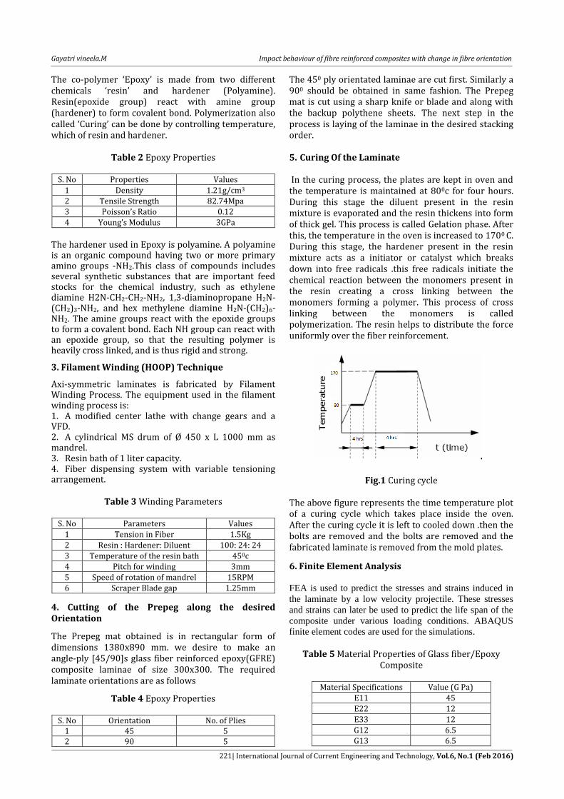
The 450 ply orientated laminae are cut first. Similarly a 900 should be obtained in same fashion. The Prepeg mat is cut using a sharp knife or blade and along with the backup polythene sheets. The next step in the process is laying of the laminae in the desired stacking order. 5. Curing Of the Laminate In the curing process, the plates are kept in oven and the temperature is maintained at 800c for four hours. During this stage the diluent present in the resin mixture is evaporated and the resin thickens into form of thick gel. This process is called Gelation phase. After this, the temperature in the oven is increased to 1700 C. During this stage, the hardener present in the resin mixture acts as a initiator or catalyst which breaks down into free radicals .this free radicals initiate the chemical reaction between the monomers present in the resin creating a cross linking between the monomers forming a polymer. This process of cross linking between the monomers is called polymerization. The resin helps to distribute the force uniformly over the fiber reinforcement.
Fig.1 Curing cycle
The above figure represents the time temperature plot of a curing cycle which takes place inside the oven. After the curing cycle it is left to cooled down .then the bolts are removed and the bolts are removed and the fabricated laminate is removed from the mold plates.
6. Finite Element Analysis FEA is used to predict the stresses and strains induced in
the laminate by a low velocity projectile. These stresses
and strains can later be used to predict the life span of the
composite under various loading conditions. ABAQUS
finite element codes are used for the simulations.
Table 5 Material Properties of Glass fiber/Epoxy Composite
Material Specifications Value (G Pa)
E11 45
E22 12
E33 12
G12 6.5
G13 6.5

Gayatri vineela.M Impact behaviour of fibre reinforced composites with change in fibre orientation
222| International Journal of Current Engineering and Technology, Vol.6, No.1 (Feb 2016)
G23 2.5
s1t 1.02
s2t 0.04
s1c 0.62
s2c 0.14
Table 6 Material Properties of Glass fiber/Epoxy
Composite
Young’s modulus (E1)
N/m2
Poisson’s ratio (ν12)
Density Kg/m3
210 x 103 0.3 7.8 x 10³
7. Modelling A solid square plate of 300mm x 300mm area and 3mm thickness is created in ABAQUS to represent a composite plate fixed. Then a sphere of 40 mm diameter is created and placed at a negligible distance from the composite plate. This sphere represents the steel impactor and it is considered as a rigid body. Fig.2 shows the model in ABAQUS.
Fig.2 Solid model
The finite element model is developed by meshing the model in ABAQUS. C3D8 element type is used to mesh the model. The meshed model is shown in the fig.5.2. The nodal components of the PLATE and IMPACTOR are created for the reference of the ABAQUS options.
Fig.3 Finite element modeling of Composite plate and Impactor
All the degrees of freedom are constrained for the circumferential surface. The impactor is given an initial velocity of 4.5m/s and acceleration of gravity 9.81
m/s2 is applied by defining array parameters for time and acceleration values in the solution. The loaded model seems as in the fig.3. 8. Analysis The loaded finite element model is ready to solve our problem. The model is solved for three different ply sequences and varying the impact velocities taken from experimental data. The type of analysis employed here is dynamic analysis. The results of the solution can be reviewed using the ABAQUS viewer. We can list or plot the results like deformation, stresses, energy, velocities etc at nodes or elements for a single load file.
Fig.4 Deformation of composite by the Impactor 9. Experimental Setup For studying the damage behavior of composite plates subjected to drop weight impacts we are fabricating drop weight impact machine. A supporting frame is used to support the composite laminate as shown in figure. An interface frame was mounted between clamps and plates for making clamping force on the composite laminates uniform.
Fig.5 Drop box setup The tests were performed using an instrumented falling weight testing machine with no energy storage device: the maximum impact energy is limited by the adjustable falling height and the fixed mass of 2.5kg of the impactor. The impactor mass together with the height of drop determines the energy of impact. With

Gayatri vineela.M Impact behaviour of fibre reinforced composites with change in fibre orientation
223| International Journal of Current Engineering and Technology, Vol.6, No.1 (Feb 2016)
an increase in mass and height the potential energy (P.E=mgh) of the impactor will increase and thus on releasing the tool holding assembly the potential energy is converted to kinetic energy (K.E=1/2mv2). Falling weight impact test setup is shown in Fig.6. The impactor material used was Mild Steel.
Fig.6 Impact test setup
In accordance with ASTM D 3029 standard[15-18] a batch of square, Area (300-300 mm side, 2.4mm thick) specimens is clamped on a supporting frame with L-Clamps , which are slotted to easy removal of laminates and to placing also. The L-Clamps provides the required clamping force. In this L-clamps were used. The impactor has a spherical head of 80 mm diameter; the impactor is hanged through a wire rope, which is passed through the two pulleys. The two pulleys are fixed to the horizontal beam in such a way that make them has free rotating without friction. Figure shows the specimen clamping apparatus, specifically designed in order to assure the constancy of the clamping force, through the pre-loading of eight L-clamps. Illustrations of the photograph of the impactor and the specimen mounted on the base plate. A fixed impactor weight of 24.5 N with the impactor was released from varying heights; 0.2, 0.3, 0.4, 0.5, 0.6, 0.7, 0.8, 0.9, 1.0, 1.1and 1.2 m according to the energy and velocity of impact required based on the laminate thickness. Scanning of the each laminate before the impact and after the impact will be done. Scanning will be done through NDT (Non-destructive testing) techniques. Here the laminates are scanned by using Ultra-sonic (C-scan) method.
Fig.7 Sample laminate before and after Impact
10. Test Results The test results of all the 3 specimen laminates are compared and tabulated
Table 7 Comparison based on Ply Angle
Orientations Frequency Before
Impact(db)
Frequency After
Impact(db) [30/60]5 40-50 36-43
[45/90]5 33-45 28-40
[0/90]5 42-48 38-45
In Ultrasound scan, Imperfections between the transmitter and receiver reduce the amount of sound transmitted, thus revealing their presence. C-scan of the laminates reveals very less deformation for the given low velocity impacts for all orientations. The scan images show that there is not much variation in damage area for low velocity impacts. [30/60]5
laminate showed more damage resistance compared to other laminates. The same is validated by the deformation contours obtained using ABAQUS. 10.1 Ultra Scan Results
Fig.8 [30/60]5 orientation before and after Impact
Fig.9 For [0/90]5 orientation before and after Impact
Fig.10 For [45/90]5 orientation before and after Impact

Gayatri vineela.M Impact behaviour of fibre reinforced composites with change in fibre orientation
224| International Journal of Current Engineering and Technology, Vol.6, No.1 (Feb 2016)
11. FEA Results
11.1 Deformation Contours
[0/90]5
[30/60]5
[45/90]5
11.2 Stress Contours The Vonmises stress contours for the laminates as obtained from the analysis in ABAQUS are given below. Stress concentration in [0/90]5 and [45/90]5 laminates is slightly more and stress concentration area is also more in the above two laminates compared to [30/60]5
laminate. The maximum Vonmises stresses are of the order of 1.424e0.02, 1.39e0.02 and 1.558e0.02 for [0/90]5, [30/60]5 and [45/90]5 respectively.
[0/90]5
[30/60]5
[45/90]5
To understand the behaviour of E-Glass/Epoxy laminates with respect to time the comparison plots of Velocity, Internal Energy, Kinetic Energy and the total energy of the plate and sphere Vs Time are given below.
11.3 Velocity
11.4 Internal energy

Gayatri vineela.M Impact behaviour of fibre reinforced composites with change in fibre orientation
225| International Journal of Current Engineering and Technology, Vol.6, No.1 (Feb 2016)
11.5 Kinetic energy
Conclusion
From the results obtained from the C SCAN we can conclude the 30/60 laminate has more damaged resistance than the other orientations Damage resistance is in the order of 450-900 < 00-900 <300-600 Three types of Glass/Epoxy composite plates were
tested, subjected to drop weight impact of 80mm
diameter mild steel sphere. The plates were clamped
and the spherical weight is made to impact at the
centre of the plates. The composite plates were tested
before and after impact first by visual inspection and
by using NDT scanning technique The damage area
was identified and marked. It was observed at such low
velocities and energy due to change in fiber
orientation, there was no significant damage reported
for all the plates. The damage might be considerably
more for high velocity impacts. However, from the
results obtained from the C SCAN we can conclude the
30/60 laminate has more damaged resistance than the
other orientations Damage resistance is in the order of
450-900 < 00-900 <300-600
To support the above test results the laminates and the impactor were modeled using ABAQUS .The deformation contours, stress contours and variation of the Velocity of the ball after impact, the change in kinetic energy and the amount of internal energy absorbed after impact were obtained. The damage area obtained by visual inspection is approximately same as that obtained from the analysis software. However, with a good experimental setup backed with accessories to measure the impact force, energy and velocity, the impact characteristics for low, medium and high velocity impacts can be studied, validated with ABAQUS tool to find an optimum ply angle sequence with good impact resistance which can be an advantageous for many industrial applications.
References Ramin Hosseinzadeh, Mahmood M Shokrieh and Larry
Lessard (2006), Damage behaviour of Fiber reinforced composite plates subjected to drop weight impacts; Comp. Sci. Tech. 66
Ramazan Karakuzu, Emere Erbil and Mehmet Aktas (June 2010). Damage prediction in glass/epoxy laminates subjected to impact loading; Indian Journal of Composites & Material Sciences Vol. 17.
Gautam S. Chandekar, Bhushan S. Thatte, and Ajit D. Kelkar. (2010), On the Behavior of Fiberglass Epoxy Composites under Low Velocity Impact Loading; Hindawi Publishing Corporation Advances in Mechanical Engineering Vol 2010.
Richardson MOW, Wisheart MJ (1996). Review of Low Velocity Impact properties of Composite Materials. Compos Part A – Appl. Sci. Manuf;27A.
Ross C A, Sierakowski R L (1973), Studies on the Impact Resistance of Composites Plates. Composites 4.
Clark G (1989), Modelling of Impact Damage in Composite Laminates. Composites; 20
N K Naik, Y Chandrashekar, Shailendra Meduri Damage in Woven Fabric Composites subjected to Low-Velocity Impact.
Antonio F Avila, Marcelo I Soares et.al (2005), An Experimental Investigation on Nanocomposites under impact loading, WIT Transactions on Engineering Sciences
Mechanics of Composite Materials by Robert M. Jones Handbook of composites, Department of Defense www. compositesworld.com www.wikipedia.org