Embed Size (px)
Citation preview
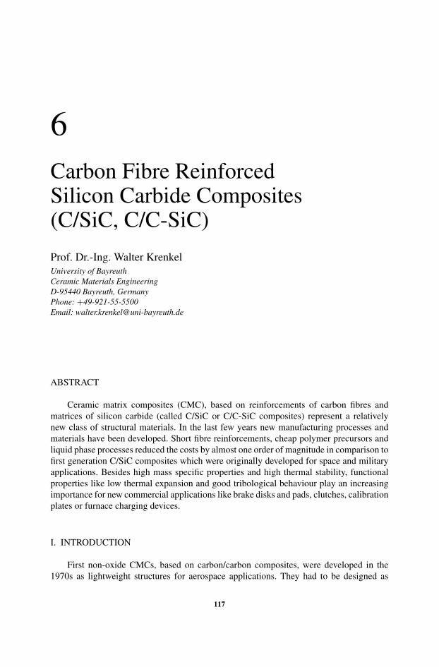
6Carbon Fibre ReinforcedSilicon Carbide Composites(C/SiC, C/C-SiC)
Prof. Dr.-Ing. Walter KrenkelUniversity of BayreuthCeramic Materials EngineeringD-95440 Bayreuth, GermanyPhone: +49-921-55-5500Email: [email protected]
ABSTRACT
Ceramic matrix composites (CMC), based on reinforcements of carbon fibres andmatrices of silicon carbide (called C/SiC or C/C-SiC composites) represent a relativelynew class of structural materials. In the last few years new manufacturing processes andmaterials have been developed. Short fibre reinforcements, cheap polymer precursors andliquid phase processes reduced the costs by almost one order of magnitude in comparison tofirst generation C/SiC composites which were originally developed for space and militaryapplications. Besides high mass specific properties and high thermal stability, functionalproperties like low thermal expansion and good tribological behaviour play an increasingimportance for new commercial applications like brake disks and pads, clutches, calibrationplates or furnace charging devices.
I. INTRODUCTION
First non-oxide CMCs, based on carbon/carbon composites, were developed in the1970s as lightweight structures for aerospace applications. They had to be designed as
117
118 WALTER KRENKEL
limited life structures as the environmental conditions were highly aggressive and the longterm behaviour of these composites was still unknown. Typical representatives for suchcomponents were rocket nozzles, engine flaps, leading edges of spacecraft and brake disksof aircraft. Their lifetime comprises several minutes to some few hours under highest ther-momechanical requirements which can not be fulfilled by any other structural material[1–3].
In order to improve the oxidation resistance and thus the application lifetime of thesecomposites, research has been exerted on using ceramics instead of carbon as the matrixmaterial. Silicon carbide is particularly suitable as a matrix material due to its high oxidationresistance, its superior temperature and thermal shock stability and its high creep resistance.Practically, similar manufacturing techniques can be used for the silicon carbide matrix for-mation of C/SiC composites as for the manufacture of carbon/carbon composites. Generally,ceramic matrix composites have been developed to combine the advantageous properties ofmonolithic ceramics with a high damage tolerance, which is known for example from thereinforcing of fibre reinforced polymers. However, the mechanisms which cause high dam-age tolerance are completely different for both classes of material. Polymers are reinforcedwith strong and stiff fibres, whereas the matrix is weak and of low strength, stiffness as wellas thermal stability. A strong bonding between matrix and fibres is desired as a result of highfibre surface reactions. Based on the differences of stiffness between fibres and polymer,the matrix itself is stressed only slightly and the energy release rate of a matrix crack is lowbecause of the modest matrix strength. Therefore, the highly loaded fibres are able to stopcracks without being damaged.
Ceramic matrix composites are characterized by the fact that the stiffness of both, fibresand matrix, are in the same order of magnitude. High fibre/matrix bonding forces result instresses which are similar for the matrix as well as for the fibres and the damage tolerance iscomparable low to monolithic ceramics. The opposite case with extremely low fibre/matrixbondings leads to a nearly stress-free matrix and a high fracture toughness. However, as thedebonding and shear properties mainly depend on frictional effects, such kind of compositesare usually not suitable as a structural material. Damage tolerant CMCs therefore requiremoderate fibre/matrix bondings with adapted interphases. The interphase microstructure canvary from sharp, non-reactive interfaces to in situ reacted interfaces, porous or multilayerinterfaces and is responsible for the stopping and deflecting of matrix cracks.
Similar to polymer and metal matrix composites, the CMC’s fracture behaviour andproperties are dominated by the reinforcing fibres. But to an even higher degree the fibresmust show a high stiffness and an extreme thermal stability. Carbon fibres fulfill theserequirements in an outstanding way. They are commercially available in various modifica-tions, weavable to preforms and carbon fibres show a very high thermal stability well above2,000 ◦C. However, their main disadvantage is the degradation in an oxidising atmospherebeyond 450 ◦C, resulting in the need for an external oxidation protection. It is known fromoxidation kinetics that increasing the final heat treatment temperature (for example by agraphitization step) results in an improved oxidation resistance of the C-fibres. Therefore,the oxidation resistance is also improved by reinforcements with high modulus (HM) orultra high modulus (UHM) carbon fibres in comparison to high tenacity (HT) fibres [4].
Long-term oxidation protection requires multilayer protection coatings, where the car-bon/carbon or carbon/silicon carbide composite is protected for example with SiC layersand additional self-healing glass forming layers, based on oxides like mullite, alumina
CARBON FIBRE REINFORCED SILICON CARBIDE COMPOSITES 119
or silicon. The silicon carbide layer can be performed via pack cementation, but supe-rior oxidation resistance can be achieved with pure �-SiC layers, deposited via the CVDprocess [5].
Due to the anisotropic coefficient of thermal expansion (CTE) of C/C, C/SiC and C/C-SiC, the oxidation protection of these composites is more difficult than it is for non-reinforcedcarbon or graphite bulk materials. The mismatch of CTE between the CVD-SiC coating andthe carbon fibre reinforcement creates cracks in the SiC coating during the cooling-downperiod after deposition. Crack formation starts at approximately 100 ◦C below the CVDcoating temperature. Therefore, CVD-SiC coated composites show the highest oxidationrate at about 800 ◦C, the maximum between crack opening and oxidation kinetics. As a result,sophisticated oxidation and corrosion coatings can only reduce the material degradation ina certain temperature interval under static conditions, but all available protection coatingsare not able to prevent oxidation completely under dynamic conditions. The designers andusers of C/SiC and C/C-SiC composites have to keep these inherent restrictions underconsideration in order to apply these materials adequately, resulting for example in shortinspection periods and higher efforts in in-service monitoring by NDE methods.
II. APPLICATIONS
C/SiC and C/C-SiC applications lie in fields where conventional materials, due totheir insufficient mechanical properties at high temperatures or limited damage tolerancebehaviour can no longer be considered and includes in principal all areas of lightweightconstruction. Some examples are given for high temperature (T > 1,000 ◦C), medium tem-perature and low temperature (T < 450 ◦C) regimes.
(2.1) Space vehicle’s TPS and Hot structures
Temperatures of up to 1,800 ◦C occur during the re-entry phase of orbiters into earth’satmosphere. Thermal protection systems (TPS) are the domain of carbon fibre reinforcedSiC-ceramics in spacecraft structures and numerous technology-driven projects have beenperformed over more than two decades in Europe, the US and Japan. The Hot structures ofNASA’s experimental space vehicle X-38, which was planed to serve as a technology carrierfor a new Crew Return Vehicle (CRV) of the International Space Station (ISS), are regardedas an example for the current stage of C/SiC and C/C-SiC development for thermal protectionsystems. A nose cap, the adjacent thermal protection panels (nose skirt), two leading edgesegments and two body flaps for the steering of the vehicle were manufactured and qualifiedby ground-tests by a German consortium [6–8].
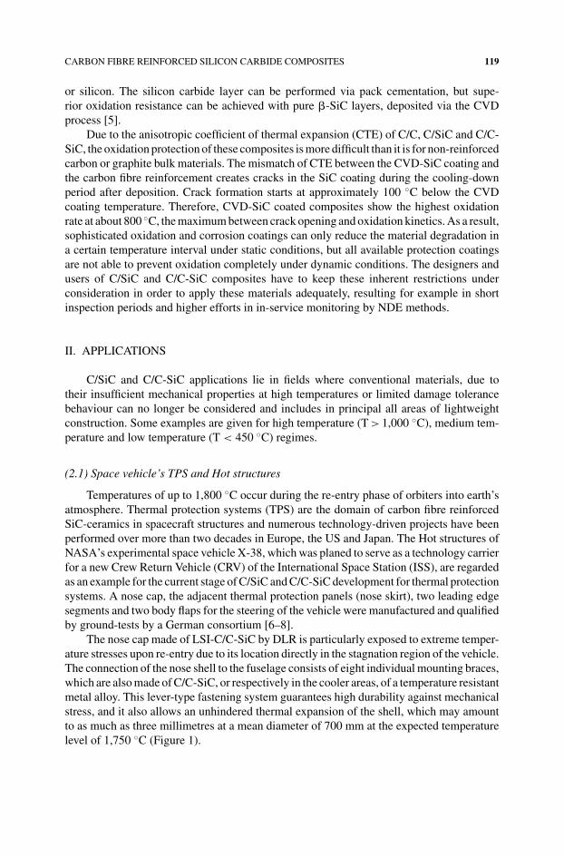
The nose cap made of LSI-C/C-SiC by DLR is particularly exposed to extreme temper-ature stresses upon re-entry due to its location directly in the stagnation region of the vehicle.The connection of the nose shell to the fuselage consists of eight individual mounting braces,which are also made of C/C-SiC, or respectively in the cooler areas, of a temperature resistantmetal alloy. This lever-type fastening system guarantees high durability against mechanicalstress, and it also allows an unhindered thermal expansion of the shell, which may amountto as much as three millimetres at a mean diameter of 700 mm at the expected temperaturelevel of 1,750 ◦C (Figure 1).
120 WALTER KRENKEL
FIG
UR
E1.
Atta
chm
entd
esig
nof
the
X-3
8no
seca
p(m
ade
ofC
/C-S
iCco
mpo
site
s)
CARBON FIBRE REINFORCED SILICON CARBIDE COMPOSITES 121
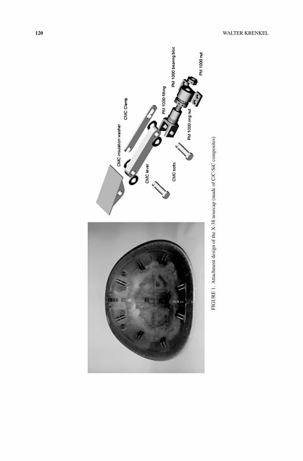
FIGURE 2. CVI-C/SiC body flaps for the X-38, joined with C/SiC screws. The Body Flap was developed byMAN-T in the frame of the German TETRA-Programme which was carried out by order of DLR and sponsoredby the BMBF and Bavarian STMWVT
The CVI-C/SiC body flaps, manufactured by MAN Technologie, are build up from fourboxes with integral transverse stiffeners and flanges to bear covers. The flaps of 1,600 mmin length and 1,500 mm in breadth are joined with more than 400 screws in total, alsomade of CVI-C/SiC (Figure 2). The use of C/SiC composites is providing about 50%weight reduction with higher safety margins compared to insulated metallic structures. TheC/SiC nose skirt was manufactured by ASTRIUM GmbH via the liquid polymer infiltrationprocess.
(2.2) Vanes, nozzles and flaps of rocket motors and jet engines
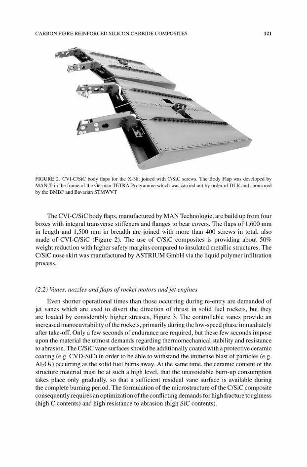
Even shorter operational times than those occurring during re-entry are demanded ofjet vanes which are used to divert the direction of thrust in solid fuel rockets, but theyare loaded by considerably higher stresses, Figure 3. The controllable vanes provide anincreased manoeuvrability of the rockets, primarily during the low-speed phase immediatelyafter take-off. Only a few seconds of endurance are required, but these few seconds imposeupon the material the utmost demands regarding thermomechanical stability and resistanceto abrasion. The C/SiC vane surfaces should be additionally coated with a protective ceramiccoating (e.g. CVD-SiC) in order to be able to withstand the immense blast of particles (e.g.Al2O3) occurring as the solid fuel burns away. At the same time, the ceramic content of thestructure material must be at such a high level, that the unavoidable burn-up consumptiontakes place only gradually, so that a sufficient residual vane surface is available duringthe complete burning period. The formulation of the microstructure of the C/SiC compositeconsequently requires an optimization of the conflicting demands for high fracture toughness(high C contents) and high resistance to abrasion (high SiC contents).
122 WALTER KRENKEL
FIGURE 3. C/C-SiC jet vanes for solid fuel rocket propulsion systems
C/SiC composites have also been investigated successfully for expansion nozzles ofrocket propulsion systems. Exemplarily, a nozzle demonstrator of the upper stage engine ofAriane 5 was designed and manufactured by filament winding, using LPI technique [9]. Thenozzle with a length of 1,360 mm and an exit diameter of 1,330 mm showed a mass of 16 kg.Although considerable thicker wall structures were necessary, weight reductions of 60% andan increase of the allowable temperature of about 500 ◦C in comparison to superalloy Haynes25 could be achieved.
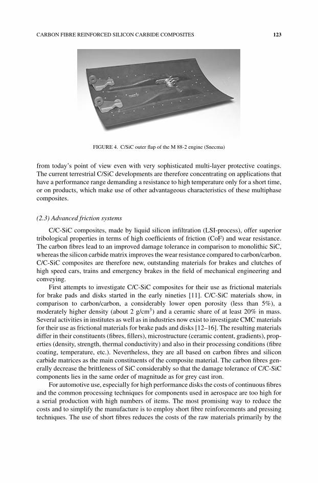
Several C/SiC components like flame-holders, exhaust cones and engine flaps haveproven their feasibility for military jet engines [10]. Outer flaps in the SNECMA M 88-2engine provide 50% weight savings over the corresponding superalloy flap (Inconel 718)and almost 300 flaps have been fabricated for ground tests (Figure 4). C/SiC engine flapsare of prime interest for future military engines where they allow the reduction of internalcooling flow, thus yielding benefits in the engine performance.
The general low resistance to oxidation of carbon only permits restricted operationalperiods of the C/SiC structures at temperatures above about 450 ◦C. Its utilization in civilaircraft turbines or stationary gas turbines (e.g. as tiles in combustion chambers, for diffusersor for turbine vanes) with operational times of several 10,000 hours is therefore not possible
CARBON FIBRE REINFORCED SILICON CARBIDE COMPOSITES 123
FIGURE 4. C/SiC outer flap of the M 88-2 engine (Snecma)
from today’s point of view even with very sophisticated multi-layer protective coatings.The current terrestrial C/SiC developments are therefore concentrating on applications thathave a performance range demanding a resistance to high temperature only for a short time,or on products, which make use of other advantageous characteristics of these multiphasecomposites.
(2.3) Advanced friction systems
C/C-SiC composites, made by liquid silicon infiltration (LSI-process), offer superiortribological properties in terms of high coefficients of friction (CoF) and wear resistance.The carbon fibres lead to an improved damage tolerance in comparison to monolithic SiC,whereas the silicon carbide matrix improves the wear resistance compared to carbon/carbon.C/C-SiC composites are therefore new, outstanding materials for brakes and clutches ofhigh speed cars, trains and emergency brakes in the field of mechanical engineering andconveying.
First attempts to investigate C/C-SiC composites for their use as frictional materialsfor brake pads and disks started in the early nineties [11]. C/C-SiC materials show, incomparison to carbon/carbon, a considerably lower open porosity (less than 5%), amoderately higher density (about 2 g/cm3) and a ceramic share of at least 20% in mass.Several activities in institutes as well as in industries now exist to investigate CMC materialsfor their use as frictional materials for brake pads and disks [12–16]. The resulting materialsdiffer in their constituents (fibres, fillers), microstructure (ceramic content, gradients), prop-erties (density, strength, thermal conductivity) and also in their processing conditions (fibrecoating, temperature, etc.). Nevertheless, they are all based on carbon fibres and siliconcarbide matrices as the main constituents of the composite material. The carbon fibres gen-erally decrease the brittleness of SiC considerably so that the damage tolerance of C/C-SiCcomponents lies in the same order of magnitude as for grey cast iron.
For automotive use, especially for high performance disks the costs of continuous fibresand the common processing techniques for components used in aerospace are too high fora serial production with high numbers of items. The most promising way to reduce thecosts and to simplify the manufacture is to employ short fibre reinforcements and pressingtechniques. The use of short fibres reduces the costs of the raw materials primarily by the
124 WALTER KRENKEL
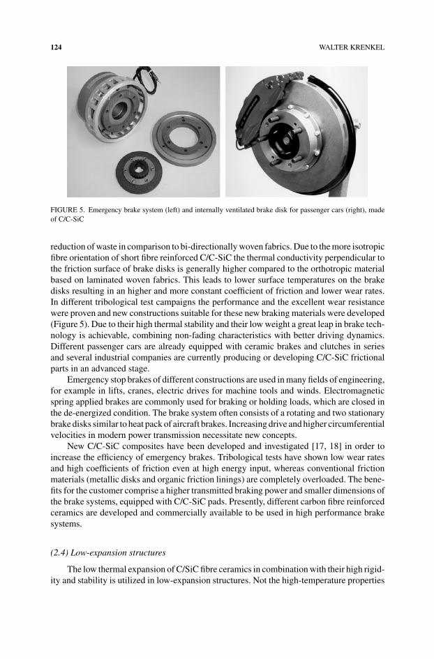
FIGURE 5. Emergency brake system (left) and internally ventilated brake disk for passenger cars (right), madeof C/C-SiC
reduction of waste in comparison to bi-directionally woven fabrics. Due to the more isotropicfibre orientation of short fibre reinforced C/C-SiC the thermal conductivity perpendicular tothe friction surface of brake disks is generally higher compared to the orthotropic materialbased on laminated woven fabrics. This leads to lower surface temperatures on the brakedisks resulting in an higher and more constant coefficient of friction and lower wear rates.In different tribological test campaigns the performance and the excellent wear resistancewere proven and new constructions suitable for these new braking materials were developed(Figure 5). Due to their high thermal stability and their low weight a great leap in brake tech-nology is achievable, combining non-fading characteristics with better driving dynamics.Different passenger cars are already equipped with ceramic brakes and clutches in seriesand several industrial companies are currently producing or developing C/C-SiC frictionalparts in an advanced stage.
Emergency stop brakes of different constructions are used in many fields of engineering,for example in lifts, cranes, electric drives for machine tools and winds. Electromagneticspring applied brakes are commonly used for braking or holding loads, which are closed inthe de-energized condition. The brake system often consists of a rotating and two stationarybrake disks similar to heat pack of aircraft brakes. Increasing drive and higher circumferentialvelocities in modern power transmission necessitate new concepts.
New C/C-SiC composites have been developed and investigated [17, 18] in order toincrease the efficiency of emergency brakes. Tribological tests have shown low wear ratesand high coefficients of friction even at high energy input, whereas conventional frictionmaterials (metallic disks and organic friction linings) are completely overloaded. The bene-fits for the customer comprise a higher transmitted braking power and smaller dimensions ofthe brake systems, equipped with C/C-SiC pads. Presently, different carbon fibre reinforcedceramics are developed and commercially available to be used in high performance brakesystems.
(2.4) Low-expansion structures
The low thermal expansion of C/SiC fibre ceramics in combination with their high rigid-ity and stability is utilized in low-expansion structures. Not the high-temperature properties
CARBON FIBRE REINFORCED SILICON CARBIDE COMPOSITES 125
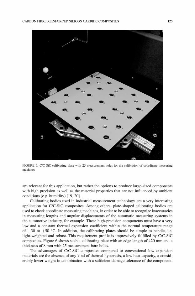
FIGURE 6. C/C-SiC calibrating plate with 25 measurement holes for the calibration of coordinate measuringmachines
are relevant for this application, but rather the options to produce large-sized componentswith high precision as well as the material properties that are not influenced by ambientconditions (e.g. humidity) [19, 20].
Calibrating bodies used in industrial measurement technology are a very interestingapplication for C/C-SiC composites. Among others, plate-shaped calibrating bodies areused to check coordinate measuring machines, in order to be able to recognize inaccuraciesin measuring lengths and angular displacements of the automatic measuring systems inthe automotive industry, for example. These high-precision components must have a verylow and a constant thermal expansion coefficient within the normal temperature rangeof −30 to +50 ◦C. In addition, the calibrating plates should be simple to handle, i.e.light-weighted and robust. This requirement profile is impressively fulfilled by C/C-SiCcomposites. Figure 6 shows such a calibrating plate with an edge length of 420 mm and athickness of 8 mm with 25 measurement bore holes.
The advantages of C/C-SiC composites compared to conventional low-expansionmaterials are the absence of any kind of thermal hysteresis, a low heat capacity, a consid-erably lower weight in combination with a sufficient damage tolerance of the component.
126 WALTER KRENKEL
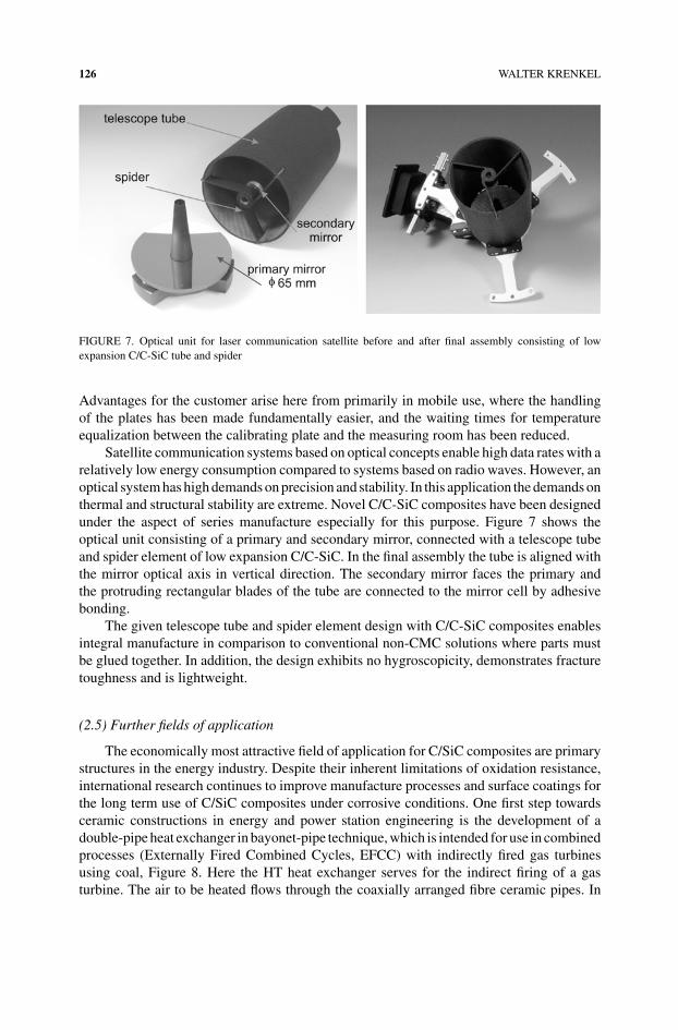
FIGURE 7. Optical unit for laser communication satellite before and after final assembly consisting of lowexpansion C/C-SiC tube and spider
Advantages for the customer arise here from primarily in mobile use, where the handlingof the plates has been made fundamentally easier, and the waiting times for temperatureequalization between the calibrating plate and the measuring room has been reduced.
Satellite communication systems based on optical concepts enable high data rates with arelatively low energy consumption compared to systems based on radio waves. However, anoptical system has high demands on precision and stability. In this application the demands onthermal and structural stability are extreme. Novel C/C-SiC composites have been designedunder the aspect of series manufacture especially for this purpose. Figure 7 shows theoptical unit consisting of a primary and secondary mirror, connected with a telescope tubeand spider element of low expansion C/C-SiC. In the final assembly the tube is aligned withthe mirror optical axis in vertical direction. The secondary mirror faces the primary andthe protruding rectangular blades of the tube are connected to the mirror cell by adhesivebonding.
The given telescope tube and spider element design with C/C-SiC composites enablesintegral manufacture in comparison to conventional non-CMC solutions where parts mustbe glued together. In addition, the design exhibits no hygroscopicity, demonstrates fracturetoughness and is lightweight.
(2.5) Further fields of application
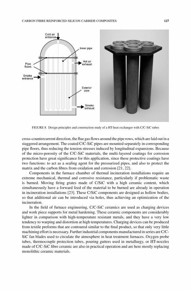
The economically most attractive field of application for C/SiC composites are primarystructures in the energy industry. Despite their inherent limitations of oxidation resistance,international research continues to improve manufacture processes and surface coatings forthe long term use of C/SiC composites under corrosive conditions. One first step towardsceramic constructions in energy and power station engineering is the development of adouble-pipe heat exchanger in bayonet-pipe technique, which is intended for use in combinedprocesses (Externally Fired Combined Cycles, EFCC) with indirectly fired gas turbinesusing coal, Figure 8. Here the HT heat exchanger serves for the indirect firing of a gasturbine. The air to be heated flows through the coaxially arranged fibre ceramic pipes. In
CARBON FIBRE REINFORCED SILICON CARBIDE COMPOSITES 127
FIGURE 8. Design principles and construction study of a HT-heat exchanger with C/C-SiC tubes
cross-countercurrent direction, the flue gas flows around the pipe rows, which are laid out in astaggered arrangement. The coated C/C-SiC pipes are mounted separately in correspondingpipe floors, thus reducing the tension stresses induced by longitudinal expansions. Becauseof the micro-porosity of the C/C-SiC materials, the multi-layered coatings for corrosionprotection have great significance for this application, since these protective coatings havetwo functions: to act as a sealing agent for the pressurized pipes, and also to protect thematrix and the carbon fibres from oxidation and corrosion [21, 22].
Components in the furnace chamber of thermal incineration installations require anextreme mechanical, thermal and corrosive resistance, particularly if problematic wasteis burned. Moving firing grates made of C/SiC with a high ceramic content, whichsimultaneously have a forward feed of the material to be burned are already in operationin incineration installations [23]. These C/SiC components are designed as hollow bodies,so that additional air can be introduced via holes, thus achieving an optimization of theincineration.
In the field of furnace engineering, C/C-SiC ceramics are used as charging devicesand work piece supports for metal hardening. These ceramic components are considerablylighter in comparison with high-temperature resistant metals, and they have a very lowtendency to warping and distortion at high temperatures. Charging devices can be producedfrom textile preforms that are contoured similar to the final product, so that only very littlemachining effort is necessary. Further industrial components manufactured in series are C/C-SiC fan blades used to circulate the atmosphere in heat treatment furnaces. Oxygen probetubes, thermocouple protection tubes, pouring gutters used in metallurgy, or HT-nozzlesmade of C/C-SiC fibre ceramic are also in practical operation and are here mostly replacingmonolithic ceramic materials.
128 WALTER KRENKEL
In the field of ballistic protection of vehicles and aircraft, the use of monolithic ceramicsin compound systems permits a weight reduction of more than 50% as compared to armorplating steels. Further-reaching mass reductions are possible for future lightweight armorby using light C/SiC or C/C-SiC plates instead of the alumina or silicon carbide materialscommonly used. Ballistic tests have shown, that fibre ceramics additionally offer improvedprotection against multiple hits because of their higher fracture toughness [24].
A typical lightweight armor principally consists of a multi-layered sandwich compound,of which the front side is made of a ceramic material and the rear side is primarily madeof energy absorbing materials, such as synthetic fabrics (e.g. aramide) or ductile metals.Aside of the potentially lower weight per unit area of such lightweight armor (goal to beachieved: <25 kg/m2), the variability in the design of the fibre ceramics is another essentialadvantage of fibre ceramics in comparison to conventional ceramics. Their manufacture isbased on the classic methods used in composites technology, which allows almost any kindof curved, thin-walled structure. The largest sales volume of future fibre ceramic production,besides brake discs, is consequently envisaged in ballistic protection systems based on C/SiCand C/C-SiC composites.
III. PROCESSING
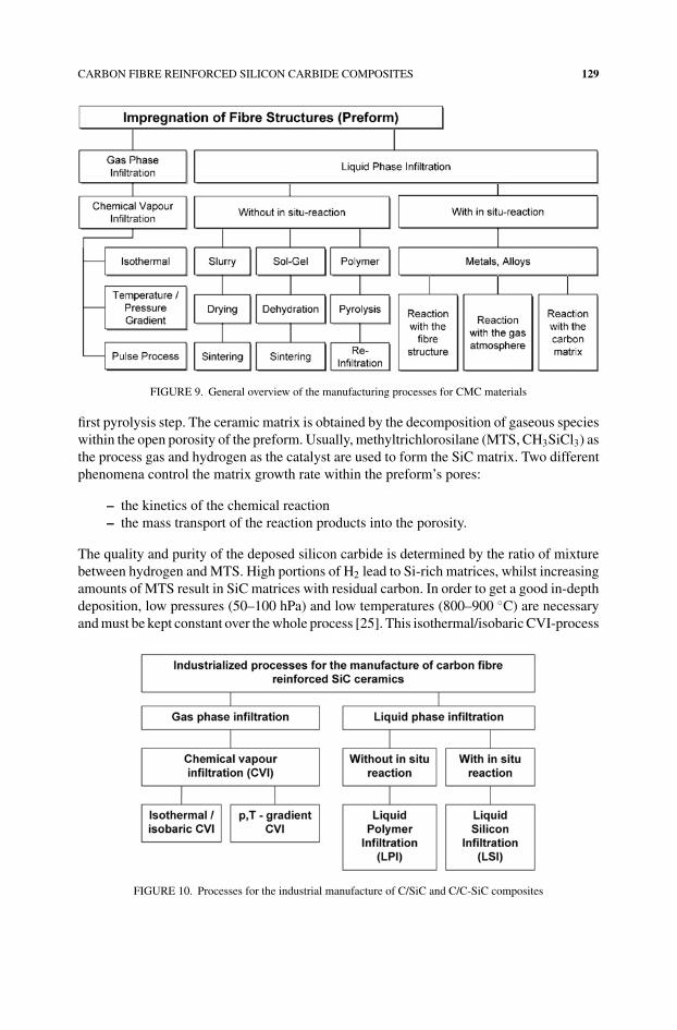
In principal, there exist numerous processing routes to infiltrate the matrix system intothe fibre preform. Conventional powder processing techniques used for making monolithicceramics are mostly not suitable and rather unconventional techniques to avoid damage ofthe fibre preforms are applied. They can be distinguished between the impregnation either bygas phase or by liquid phase infiltration (Figure 9). Three different techniques are currentlyused in an industrial scale for the production of C/SiC and C/C-SiC composites, each ofthem leading to specific microstructures and properties (Figure 10):
– Chemical Vapour Infiltration (CVI)– Liquid Polymer Infiltration (LPI) or Polymer Infiltration and Pyrolysis (PIP)– Liquid Silicon Infiltration (LSI)
Historically, the processing routes moved from the isothermal CVI process to more cost-effective techniques such as gradient-CVI and liquid polymer or liquid silicon infiltration.These routes are faster and lead to shorter manufacture cycles than isothermal CVI and,especially the two liquid phase processes LPI and LSI, use technologies already developedfor polymer matrix composites (PMC).
One important aspect is to realize that processing should be considered as an integralpart of the whole process of designing a CMC component. Fibre orientation, dimensionalityof the preform and thermal treatment conditions are important parameters of influence forthe performance of the final CMC product.
(3.1) Chemical Vapour Infiltration
Chemical vapour infiltration in general allows the deposit of quite a variety of matricesand the processing of any complex shape. The multi-directional fibre preform is fixed in thefurnace with a tooling or build-up with a temporary binding agent, which is removed in a
CARBON FIBRE REINFORCED SILICON CARBIDE COMPOSITES 129
FIGURE 9. General overview of the manufacturing processes for CMC materials
first pyrolysis step. The ceramic matrix is obtained by the decomposition of gaseous specieswithin the open porosity of the preform. Usually, methyltrichlorosilane (MTS, CH3SiCl3) asthe process gas and hydrogen as the catalyst are used to form the SiC matrix. Two differentphenomena control the matrix growth rate within the preform’s pores:
– the kinetics of the chemical reaction– the mass transport of the reaction products into the porosity.
The quality and purity of the deposed silicon carbide is determined by the ratio of mixturebetween hydrogen and MTS. High portions of H2 lead to Si-rich matrices, whilst increasingamounts of MTS result in SiC matrices with residual carbon. In order to get a good in-depthdeposition, low pressures (50–100 hPa) and low temperatures (800–900 ◦C) are necessaryand must be kept constant over the whole process [25]. This isothermal/isobaric CVI-process
FIGURE 10. Processes for the industrial manufacture of C/SiC and C/C-SiC composites
130 WALTER KRENKEL
leads to very good thermomechanical properties and high fracture toughness. The drawbackslie in long processing times lasting several weeks or months and in restricted preform depthswhich can be infiltrated in one step.
To overcome these geometrical restrictions and to increase the deposit rate of SiC, ther-mal and pressure gradient-CVI processes have been developed and industrialized [26, 27].In contrast to the isothermal CVI process a forced mass flow of MTS, driven by gradientsof temperature and pressure within the preform, is applied and allows considerable higherprocess temperatures and pressures. The higher gas density and higher reaction speed resultin manufacture times which are more than one order of magnitude faster than the isother-mal/isobaric CVI. Typically, 40 to 60 hours are necessary to infiltrate carbon preforms of5 mm thickness to a residual open porosity of 12%. As the forced mass flow of gases neces-sitate the sealing and cooling of the fibre preform, this variant on CVI is focussed on simpleand standardized geometries like profiles, tubes and plates.
Besides the good quality of the C/SiC composites processed by chemical vapour infil-tration, one of the major advantages of this manufacturing route is that is allows the controlof the fibre/matrix interphase. Therefore, C/SiC composites are shortly deposited in a firststep with carbon (e.g. by the deposition of methane gas, CH4) to govern the fibre/matrixbonding forces. In summary, the manufacture of C/SiC components via the gradient-CVIprocess comprises the following steps:
1. Fibre preform build-up with a polymer binding agent2. Pyrolysis of the polymer (leads to a self-supporting fibre preform)3. Deposition of carbon for fibre coating (interphase formation)4. Deposition of SiC for matrix infiltration5. Final machining of the near-net shaped C/SiC component
(3.2) Liquid Polymer Infiltration
The manufacture of C/SiC components by using polymeric precursors is called liquidpolymer infiltration (LPI) process or polymer infiltration and pyrolysis (PIP) process andrepresents one of the most advanced manufacturing methods for large and complex shapedCMC parts for the aerospace industry [28–30]. The starting materials to form the siliconcarbide matrix are usually polycarbosilane or polysilane polymers which convert frompolymer to an amorphous or crystalline ceramic during pyrolysis. The big difference in thedensities of the polymeric precursor and the SiC matrix results in a reduction of volume andinduces a high amount of pores in the matrix. Inert submicronic SiC particles or reactivefillers can be used to reduce the shrinkage, but usually a number of successive infiltrationcycles followed by a respective pyrolysis step are required to obtain a SiC matrix witha sufficient high density. Typically, five to seven impregnations are necessary to obtain aresidual porosity of less than 10%.
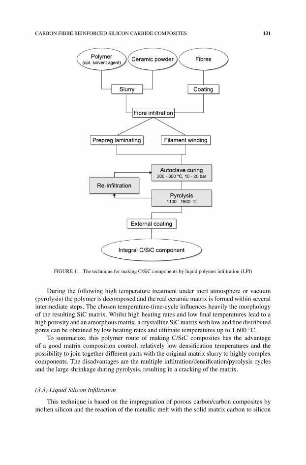
Figure 11 gives an overview of the LPI-process which is used for the manufacture ofintegral C/SiC components. Prior to their slurry infiltration the carbon fibres are coatedby CVD to reduce the fibre/matrix bonding. In the following steps, the processing routefollows the classical methods of manufacturing carbon fibre reinforced plastics (CFRP).The coated fibres are infiltrated with the precursor, for example by filament winding, fabricprepreging or resin transfer moulding (RTM). The resulting laminate is subsequently curedin an autoclave at 200–300 ◦C.
CARBON FIBRE REINFORCED SILICON CARBIDE COMPOSITES 131
FIGURE 11. The technique for making C/SiC components by liquid polymer infiltration (LPI)
During the following high temperature treatment under inert atmosphere or vacuum(pyrolysis) the polymer is decomposed and the real ceramic matrix is formed within severalintermediate steps. The chosen temperature-time-cycle influences heavily the morphologyof the resulting SiC matrix. Whilst high heating rates and low final temperatures lead to ahigh porosity and an amorphous matrix, a crystalline SiC matrix with low and fine distributedpores can be obtained by low heating rates and ultimate temperatures up to 1,600 ◦C.
To summarize, this polymer route of making C/SiC composites has the advantageof a good matrix composition control, relatively low densification temperatures and thepossibility to join together different parts with the original matrix slurry to highly complexcomponents. The disadvantages are the multiple infiltration/densification/pyrolysis cyclesand the large shrinkage during pyrolysis, resulting in a cracking of the matrix.
(3.3) Liquid Silicon Infiltration
This technique is based on the impregnation of porous carbon/carbon composites bymolten silicon and the reaction of the metallic melt with the solid matrix carbon to silicon
132 WALTER KRENKEL
carbide. The melt infiltration process can use almost any reinforced geometry and yieldsa high-density, low-porous matrix. A fibre preform having a network of pores and cracksis infiltrated by liquid silicon, mostly using capillary pressure. Application of pressure orprocessing in vacuum can support the infiltration process. The temperatures involved are atleast beyond the melting point of silicon (1,415 ◦C) and can lead to deleterious reactionsbetween the fibres and silicon. The melt viscosity, the chemical reactivity, the wetting ofthe reinforcement and the anomaly of silicon during phase transition (change of densityof approximately 8%) are critical processing parameters to be considered. The thermalexpansion mismatch between the fibres and the matrix and the rather large temperatureinterval between the processing temperature and room temperature are problems whichhave to be taken into account.
First attempts to infiltrate carbon/carbon composites by liquid silicon have been con-ducted for more than twenty years [31–33]. After these basic investigations, the carbonfibres have to be coated prior to the infiltration of silicon in order to reduce the degree offibre degradation. Also, highly graphitized carbon fibres like high modulus fibres (HM) arerecommended as reinforcement for the fibre preform which are more stable in contact withsilicon than only carbonized fibres. Both requirements are in contrast with a cost-efficientprocessing of CMCs and only poor fracture toughnesses have been achieved by the infiltra-tion of unadapted carbon/carbon preforms. In the last few years, new processes and novelC/C-composites with adapted microstructures which also allow the use of uncoated andchopped high tenacity (HT) carbon fibres were developed [34–37].
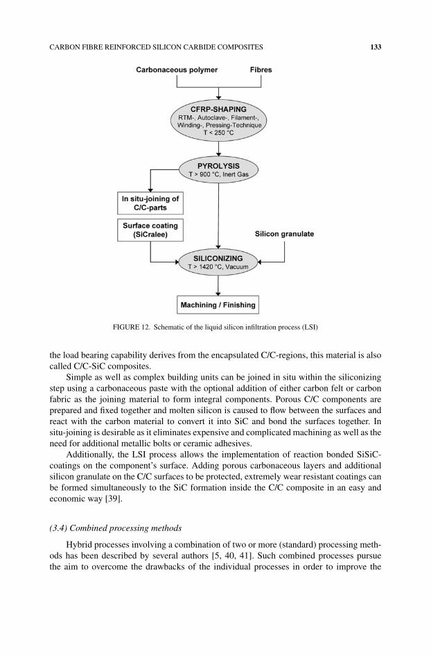
Figure 12 gives an overview of the LSI-process which can be split into three majorsteps. The fibre preform fabrication starts with the manufacture of carbon fibre reinforcedplastic composites with polymeric matrices of high carbon yield. Normally, commerciallyavailable resins like phenolics or other aromatic polymers are used to fabricate laminatesby common CFRP techniques like resin transfer moulding, autoclave, warm pressing orfilament winding. After curing, the composites are postcured for the complete polymer-ization of the matrix. Subsequently, the CFRP composites are pyrolysed under inert at-mosphere (e.g. nitrogen or vacuum) at temperature beyond 900 ◦C to convert the polymermatrix to amorphous carbon. The pyrolysis of the CFRP composite leads to a volumet-ric contraction of about 50% of the neat polymer. As this polymer contraction is hin-dered by the embedded fibres the macroscopical shrinkage of the composites is essentiallylower. In direction of the fibre alignment the shrinkage is close to zero with the resultthat the matrix contraction leads to a microscopical network of cracks within the C/Ccomposites.
The fibre/matrix bonding (FMB) strength in the polymer composite plays an importantrole during the pyrolysis step and can be modified by fibre coatings (e.g. PyC), thermalpre-treatments of the fibres or by variation of the fibre type. Generally, the higher the FMBstrength the higher the tendency to form dense segments of fibres, interconnected with atranslaminar crack system [38]. These microcracks represent the open porosity of the C/Ccomposite.
During the third and final processing step, the capillary effect of the open pores and thelow viscosity of molten silicon enable a quick filling of the microcracks. The simultaneousexothermic reaction between the carbon matrix and the liquid silicon results in silicon carbideencapsulated carbon fibres. The resulting composite comprises of three phases: carbon fibresand residual carbon matrix, silicon carbide and a certain amount of unreacted silicon. As
CARBON FIBRE REINFORCED SILICON CARBIDE COMPOSITES 133
FIGURE 12. Schematic of the liquid silicon infiltration process (LSI)
the load bearing capability derives from the encapsulated C/C-regions, this material is alsocalled C/C-SiC composites.
Simple as well as complex building units can be joined in situ within the siliconizingstep using a carbonaceous paste with the optional addition of either carbon felt or carbonfabric as the joining material to form integral components. Porous C/C components areprepared and fixed together and molten silicon is caused to flow between the surfaces andreact with the carbon material to convert it into SiC and bond the surfaces together. Insitu-joining is desirable as it eliminates expensive and complicated machining as well as theneed for additional metallic bolts or ceramic adhesives.
Additionally, the LSI process allows the implementation of reaction bonded SiSiC-coatings on the component’s surface. Adding porous carbonaceous layers and additionalsilicon granulate on the C/C surfaces to be protected, extremely wear resistant coatings canbe formed simultaneously to the SiC formation inside the C/C composite in an easy andeconomic way [39].
(3.4) Combined processing methods
Hybrid processes involving a combination of two or more (standard) processing meth-ods has been described by several authors [5, 40, 41]. Such combined processes pursuethe aim to overcome the drawbacks of the individual processes in order to improve the
134 WALTER KRENKEL
performance of the CMC material or to make the manufacture more cost-efficient. For ex-ample, a combined CVI/LPI impregnation technique is used for the industrial manufacture offilament wound furnace parts and crucibles. A pre-densification via CVI leads to the format-ion of an interphase between fibres and SiC-matrix whilst the subsequent precursor infiltra-tion fills up the matrix. In comparison to a pure LPI-process, this hybrid process reduces thenumber of reimpregnation steps and improves the mechanical properties of the composite.If the last LPI-impregnation steps are substituted by the infiltration of liquid silicon, theprocessing time can be reduced further and matrices of low porosity can be obtained.
One other approach is the combination of a first CVI step, followed by a matrix densifi-cation via liquid silicon infiltration (LSI). By chemical vapour deposition the carbon fibresare coated with pyro-carbon or boron nitride in order to prevent them from reacting withthe molten silicon and to improve the fracture toughness of the composite. The followinginfiltration of silicon densifies the matrix, resulting in a residual amount of free silicon inthe matrix. The combination of LPI and LSI processes pursues a similar goal: The coatingof C-fibres with a polymer in an initial step reduces the reaction between the fibres and thesubsequently infiltrated silicon.
Despite their heterogeneous microstructure and their complex processing, hybrid pro-cesses show a promising route to combine the high material purity and process controllabilityof the chemical vapour infiltration technique with the less time consuming and in most casescheaper liquid phase infiltration techniques of LSI and LPI. However, additional researchand development have to be done in order to take benefit of the whole potential of combinedprocesses.
IV. PROPERTIES
(4.1) General remarks
Ceramic composite materials are different from all other composite materials due to theirmicroporous and microcracked matrix. In comparison with metals, the fracture behaviourof the CMC-materials is still relatively brittle. However, their strain to failure is up toone order of magnitude greater than monolithic ceramics, and their non-linear stress-strainbehaviour make them an engineering material with quasi-ductile breaking behaviour. Evenif a comparison with grey cast iron is not permissible because of the completely differentstructure, the damage tolerance of the fibre ceramics can be compared with that of greycast iron in first approximation: These materials are still very brittle from the designer’sviewpoint familiar with metals, the ceramist, however, will regard CMC materials as anew class of materials, opening completely new fields of application due to their fracturetoughness. Low material densities result in mass-specific properties, which are unsurpassedby other structural materials at temperatures above 1,000 ◦C. Generally, the properties offibre ceramics depend strongly on their micro-structural composition, and therefore, alsoon the respective manufacturing method.
Typical properties of two-dimensionally reinforced C/SiC and C/C-SiC composites,fabricated by the isothermal CVI-, gradient CVI-, LPI- and LSI-process, respectively, areshown in Table 1, published by representative manufacturers [9, 35, 42, 43]. The varianceof properties depends on the fibre type and on the fibre volume content which is governedby the design of the component and the method of preform manufacture. The given values
CARBON FIBRE REINFORCED SILICON CARBIDE COMPOSITES 135
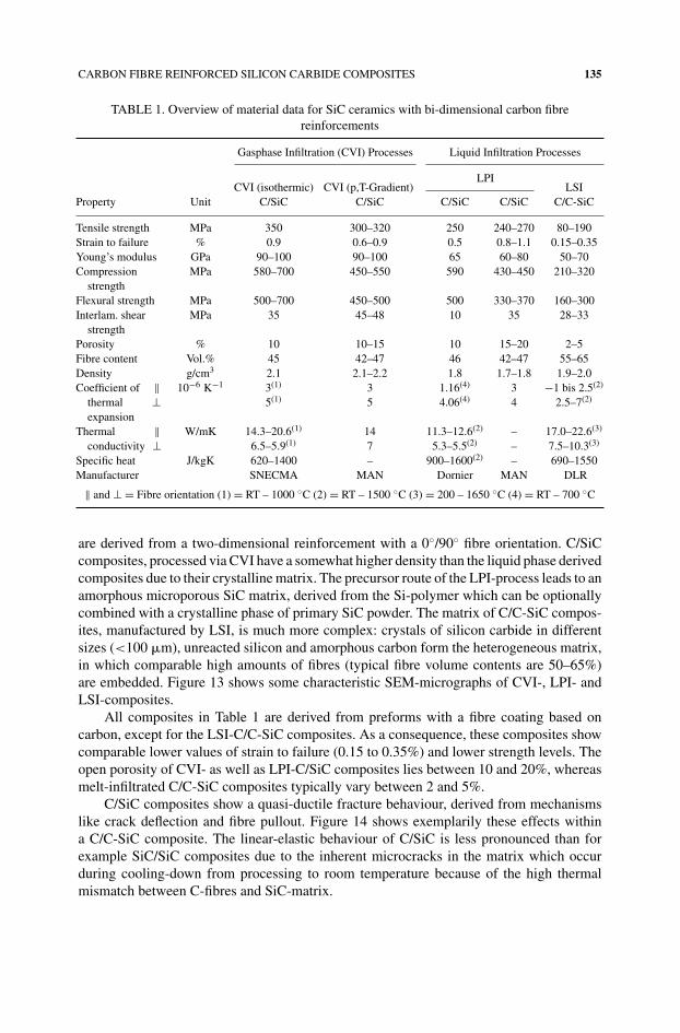
TABLE 1. Overview of material data for SiC ceramics with bi-dimensional carbon fibrereinforcements
Gasphase Infiltration (CVI) Processes Liquid Infiltration Processes
LPICVI (isothermic) CVI (p,T-Gradient) LSI
Property Unit C/SiC C/SiC C/SiC C/SiC C/C-SiC
Tensile strength MPa 350 300–320 250 240–270 80–190Strain to failure % 0.9 0.6–0.9 0.5 0.8–1.1 0.15–0.35Young’s modulus GPa 90–100 90–100 65 60–80 50–70Compression
strengthMPa 580–700 450–550 590 430–450 210–320
Flexural strength MPa 500–700 450–500 500 330–370 160–300Interlam. shear
strengthMPa 35 45–48 10 35 28–33
Porosity % 10 10–15 10 15–20 2–5Fibre content Vol.% 45 42–47 46 42–47 55–65Density g/cm3 2.1 2.1–2.2 1.8 1.7–1.8 1.9–2.0Coefficient of ‖ 10−6 K−1 3(1) 3 1.16(4) 3 −1 bis 2.5(2)
thermal ⊥ 5(1) 5 4.06(4) 4 2.5–7(2)
expansionThermal ‖ W/mK 14.3–20.6(1) 14 11.3–12.6(2) – 17.0–22.6(3)
conductivity ⊥ 6.5–5.9(1) 7 5.3–5.5(2) – 7.5–10.3(3)
Specific heat J/kgK 620–1400 – 900–1600(2) – 690–1550Manufacturer SNECMA MAN Dornier MAN DLR
‖ and ⊥ = Fibre orientation (1) = RT – 1000 ◦C (2) = RT – 1500 ◦C (3) = 200 – 1650 ◦C (4) = RT – 700 ◦C
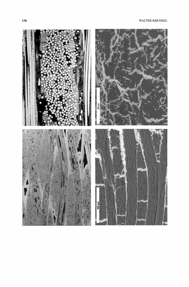
are derived from a two-dimensional reinforcement with a 0◦/90◦ fibre orientation. C/SiCcomposites, processed via CVI have a somewhat higher density than the liquid phase derivedcomposites due to their crystalline matrix. The precursor route of the LPI-process leads to anamorphous microporous SiC matrix, derived from the Si-polymer which can be optionallycombined with a crystalline phase of primary SiC powder. The matrix of C/C-SiC compos-ites, manufactured by LSI, is much more complex: crystals of silicon carbide in differentsizes (<100 �m), unreacted silicon and amorphous carbon form the heterogeneous matrix,in which comparable high amounts of fibres (typical fibre volume contents are 50–65%)are embedded. Figure 13 shows some characteristic SEM-micrographs of CVI-, LPI- andLSI-composites.
All composites in Table 1 are derived from preforms with a fibre coating based oncarbon, except for the LSI-C/C-SiC composites. As a consequence, these composites showcomparable lower values of strain to failure (0.15 to 0.35%) and lower strength levels. Theopen porosity of CVI- as well as LPI-C/SiC composites lies between 10 and 20%, whereasmelt-infiltrated C/C-SiC composites typically vary between 2 and 5%.
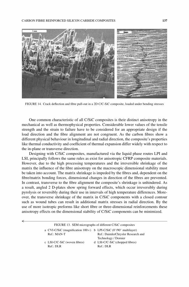
C/SiC composites show a quasi-ductile fracture behaviour, derived from mechanismslike crack deflection and fibre pullout. Figure 14 shows exemplarily these effects withina C/C-SiC composite. The linear-elastic behaviour of C/SiC is less pronounced than forexample SiC/SiC composites due to the inherent microcracks in the matrix which occurduring cooling-down from processing to room temperature because of the high thermalmismatch between C-fibres and SiC-matrix.
136 WALTER KRENKEL
CARBON FIBRE REINFORCED SILICON CARBIDE COMPOSITES 137
FIGURE 14. Crack deflection and fibre pull-out in a 2D C/C-SiC composite, loaded under bending stresses
One common characteristic of all C/SiC composites is their distinct anisotropy in themechanical as well as thermophysical properties. Considerable lower values of the tensilestrength and the strain to failure have to be considered for an appropriate design if theload direction and the fibre alignment are not congruent. As the carbon fibres show adifferent physical behaviour in longitudinal and radial direction, the composite’s propertieslike thermal conductivity and coefficient of thermal expansion differ widely with respect tothe in-plane or transverse direction.
Designing with C/SiC composites, manufactured via the liquid phase routes LPI andLSI, principally follows the same rules as exist for anisotropic CFRP composite materials.However, due to the high processing temperatures and the irreversible shrinkage of thematrix the influence of the fibre anisotropy on the macroscopic dimensional stability mustbe taken into account. The matrix shrinkage is impeded by the fibres and, dependent on thefibre/matrix bonding forces, dimensional changes in direction of the fibres are prevented.In contrast, transverse to the fibre alignment the composite’s shrinkage is unhindered. Asa result, angled 2 D-plates show spring forward effects, which occur irreversibly duringpyrolysis or reversibly during their use in intervals of high temperature differences. More-over, the transverse shrinkage of the matrix in C/SiC components with a closed contoursuch as wound tubes can result in additional matrix stresses in radial direction. By theuse of more isotropic preforms like short fibre or three-dimensional reinforcements theseanisotropy effects on the dimensional stability of C/SiC components can be minimized.
<FIGURE 13. SEM micrographs of different C/SiC composites
a CVI-C/SiC (magnification 100×) b LPI-C/SiC (0◦/90◦ multilayer)Ref.: MAN-T Ref.: DaimlerChrysler Research and
Technology / Dornierc LSI-C/C-SiC (woven fibres) d LSI-C/C-SiC (chopped fibres)
Ref.: DLR Ref.: DLR
138 WALTER KRENKEL
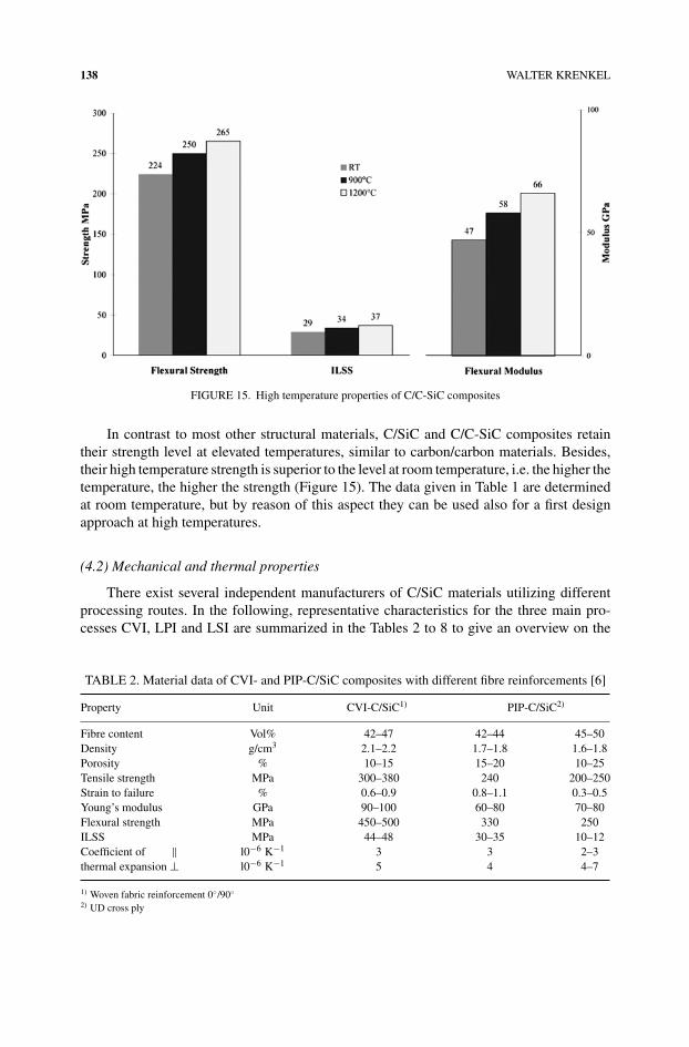
FIGURE 15. High temperature properties of C/C-SiC composites
In contrast to most other structural materials, C/SiC and C/C-SiC composites retaintheir strength level at elevated temperatures, similar to carbon/carbon materials. Besides,their high temperature strength is superior to the level at room temperature, i.e. the higher thetemperature, the higher the strength (Figure 15). The data given in Table 1 are determinedat room temperature, but by reason of this aspect they can be used also for a first designapproach at high temperatures.
(4.2) Mechanical and thermal properties
There exist several independent manufacturers of C/SiC materials utilizing differentprocessing routes. In the following, representative characteristics for the three main pro-cesses CVI, LPI and LSI are summarized in the Tables 2 to 8 to give an overview on the
TABLE 2. Material data of CVI- and PIP-C/SiC composites with different fibre reinforcements [6]
Property Unit CVI-C/SiC1) PIP-C/SiC2)
Fibre content Vol% 42–47 42–44 45–50Density g/cm3 2.1–2.2 1.7–1.8 1.6–1.8Porosity % 10–15 15–20 10–25Tensile strength MPa 300–380 240 200–250Strain to failure % 0.6–0.9 0.8–1.1 0.3–0.5Young’s modulus GPa 90–100 60–80 70–80Flexural strength MPa 450–500 330 250ILSS MPa 44–48 30–35 10–12Coefficient of ‖ l0−6 K−1 3 3 2–3thermal expansion ⊥ l0−6 K−1 5 4 4–7
1) Woven fabric reinforcement 0◦/90◦2) UD cross ply
CARBON FIBRE REINFORCED SILICON CARBIDE COMPOSITES 139
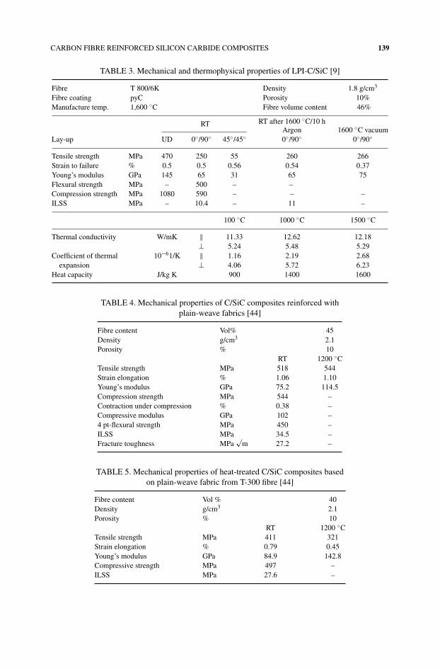
TABLE 3. Mechanical and thermophysical properties of LPI-C/SiC [9]
Fibre T 800/6K Density 1.8 g/cm3
Fibre coating pyC Porosity 10%Manufacture temp. 1,600 ◦C Fibre volume content 46%
RT RT after 1600 ◦C/10 hArgon 1600 ◦C vacuum
Lay-up UD 0◦/90◦ 45◦/45◦ 0◦/90◦ 0◦/90◦
Tensile strength MPa 470 250 55 260 266Strain to failure % 0.5 0.5 0.56 0.54 0.37Young’s modulus GPa 145 65 31 65 75Flexural strength MPa – 500 – –Compression strength MPa 1080 590 – – –ILSS MPa – 10.4 – 11 –
100 ◦C 1000 ◦C 1500 ◦C
Thermal conductivity W/mK ‖ 11.33 12.62 12.18⊥ 5.24 5.48 5.29
Coefficient of thermal 10−61/K ‖ 1.16 2.19 2.68expansion ⊥ 4.06 5.72 6.23
Heat capacity J/kg K 900 1400 1600
TABLE 4. Mechanical properties of C/SiC composites reinforced withplain-weave fabrics [44]
Fibre content Vol% 45Density g/cm3 2.1Porosity % 10
RT 1200 ◦CTensile strength MPa 518 544Strain elongation % 1.06 1.10Young’s modulus GPa 75.2 114.5Compression strength MPa 544 –Contraction under compression % 0.38 –Compressive modulus GPa 102 –4 pt-flexural strength MPa 450 –ILSS MPa 34.5 –Fracture toughness MPa
√m 27.2 –
TABLE 5. Mechanical properties of heat-treated C/SiC composites basedon plain-weave fabric from T-300 fibre [44]
Fibre content Vol % 40Density g/cm3 2.1Porosity % 10
RT 1200 ◦CTensile strength MPa 411 321Strain elongation % 0.79 0.45Young’s modulus GPa 84.9 142.8Compressive strength MPa 497 –ILSS MPa 27.6 –
140 WALTER KRENKEL
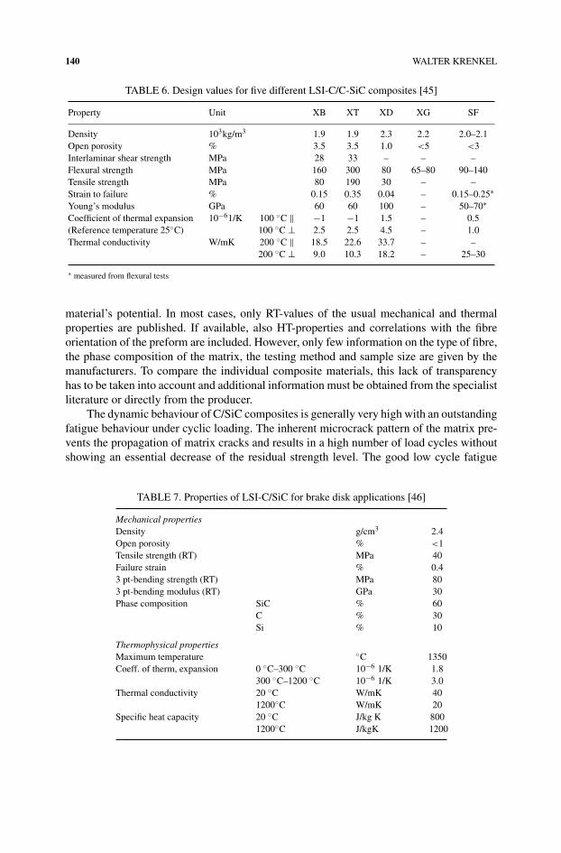
TABLE 6. Design values for five different LSI-C/C-SiC composites [45]
Property Unit XB XT XD XG SF
Density 103kg/m3 1.9 1.9 2.3 2.2 2.0–2.1Open porosity % 3.5 3.5 1.0 <5 <3Interlaminar shear strength MPa 28 33 – – –Flexural strength MPa 160 300 80 65–80 90–140Tensile strength MPa 80 190 30 – –Strain to failure % 0.15 0.35 0.04 – 0.15–0.25∗Young’s modulus GPa 60 60 100 – 50–70∗Coefficient of thermal expansion 10−61/K 100 ◦C ‖ −1 −1 1.5 – 0.5(Reference temperature 25◦C) 100 ◦C ⊥ 2.5 2.5 4.5 – 1.0Thermal conductivity W/mK 200 ◦C ‖ 18.5 22.6 33.7 – –
200 ◦C ⊥ 9.0 10.3 18.2 – 25–30
∗ measured from flexural tests
material’s potential. In most cases, only RT-values of the usual mechanical and thermalproperties are published. If available, also HT-properties and correlations with the fibreorientation of the preform are included. However, only few information on the type of fibre,the phase composition of the matrix, the testing method and sample size are given by themanufacturers. To compare the individual composite materials, this lack of transparencyhas to be taken into account and additional information must be obtained from the specialistliterature or directly from the producer.
The dynamic behaviour of C/SiC composites is generally very high with an outstandingfatigue behaviour under cyclic loading. The inherent microcrack pattern of the matrix pre-vents the propagation of matrix cracks and results in a high number of load cycles withoutshowing an essential decrease of the residual strength level. The good low cycle fatigue
TABLE 7. Properties of LSI-C/SiC for brake disk applications [46]
Mechanical propertiesDensity g/cm3 2.4Open porosity % <1Tensile strength (RT) MPa 40Failure strain % 0.43 pt-bending strength (RT) MPa 803 pt-bending modulus (RT) GPa 30Phase composition SiC % 60
C % 30Si % 10
Thermophysical propertiesMaximum temperature ◦C 1350Coeff. of therm, expansion 0 ◦C–300 ◦C 10−6 1/K 1.8
300 ◦C–1200 ◦C 10−6 1/K 3.0Thermal conductivity 20 ◦C W/mK 40
1200◦C W/mK 20Specific heat capacity 20 ◦C J/kg K 800
1200◦C J/kgK 1200
CARBON FIBRE REINFORCED SILICON CARBIDE COMPOSITES 141
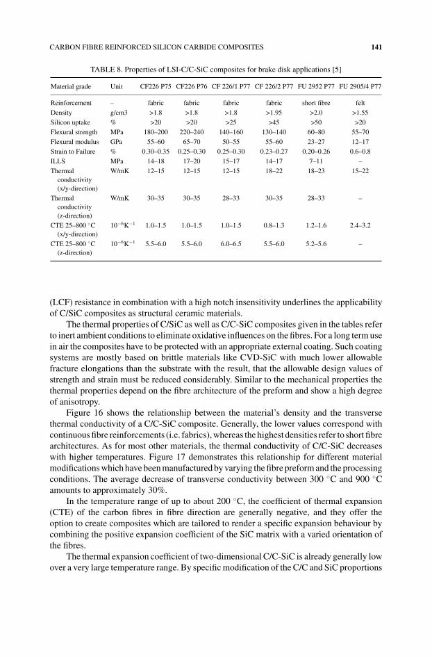
TABLE 8. Properties of LSI-C/C-SiC composites for brake disk applications [5]
Material grade Unit CF226 P75 CF226 P76 CF 226/1 P77 CF 226/2 P77 FU 2952 P77 FU 2905/4 P77
Reinforcement – fabric fabric fabric fabric short fibre felt
Density g/cm3 >1.8 >1.8 >1.8 >1.95 >2.0 >1.55
Silicon uptake % >20 >20 >25 >45 >50 >20
Flexural strength MPa 180–200 220–240 140–160 130–140 60–80 55–70
Flexural modulus GPa 55–60 65–70 50–55 55–60 23–27 12–17
Strain to Failure % 0.30–0.35 0.25–0.30 0.25–0.30 0.23–0.27 0.20–0.26 0.6–0.8
ILLS MPa 14–18 17–20 15–17 14–17 7–11 –
Thermalconductivity(x/y-direction)
W/mK 12–15 12–15 12–15 18–22 18–23 15–22
Thermalconductivity(z-direction)
W/mK 30–35 30–35 28–33 30–35 28–33 –
CTE 25–800 ◦C(x/y-direction)
10−6K−1 1.0–1.5 1.0–1.5 1.0–1.5 0.8–1.3 1.2–1.6 2.4–3.2
CTE 25–800 ◦C(z-direction)
10−6K−1 5.5–6.0 5.5–6.0 6.0–6.5 5.5–6.0 5.2–5.6 –
(LCF) resistance in combination with a high notch insensitivity underlines the applicabilityof C/SiC composites as structural ceramic materials.
The thermal properties of C/SiC as well as C/C-SiC composites given in the tables referto inert ambient conditions to eliminate oxidative influences on the fibres. For a long term usein air the composites have to be protected with an appropriate external coating. Such coatingsystems are mostly based on brittle materials like CVD-SiC with much lower allowablefracture elongations than the substrate with the result, that the allowable design values ofstrength and strain must be reduced considerably. Similar to the mechanical properties thethermal properties depend on the fibre architecture of the preform and show a high degreeof anisotropy.
Figure 16 shows the relationship between the material’s density and the transversethermal conductivity of a C/C-SiC composite. Generally, the lower values correspond withcontinuous fibre reinforcements (i.e. fabrics), whereas the highest densities refer to short fibrearchitectures. As for most other materials, the thermal conductivity of C/C-SiC decreaseswith higher temperatures. Figure 17 demonstrates this relationship for different materialmodifications which have been manufactured by varying the fibre preform and the processingconditions. The average decrease of transverse conductivity between 300 ◦C and 900 ◦Camounts to approximately 30%.
In the temperature range of up to about 200 ◦C, the coefficient of thermal expansion(CTE) of the carbon fibres in fibre direction are generally negative, and they offer theoption to create composites which are tailored to render a specific expansion behaviour bycombining the positive expansion coefficient of the SiC matrix with a varied orientation ofthe fibres.
The thermal expansion coefficient of two-dimensional C/C-SiC is already generally lowover a very large temperature range. By specific modification of the C/C and SiC proportions
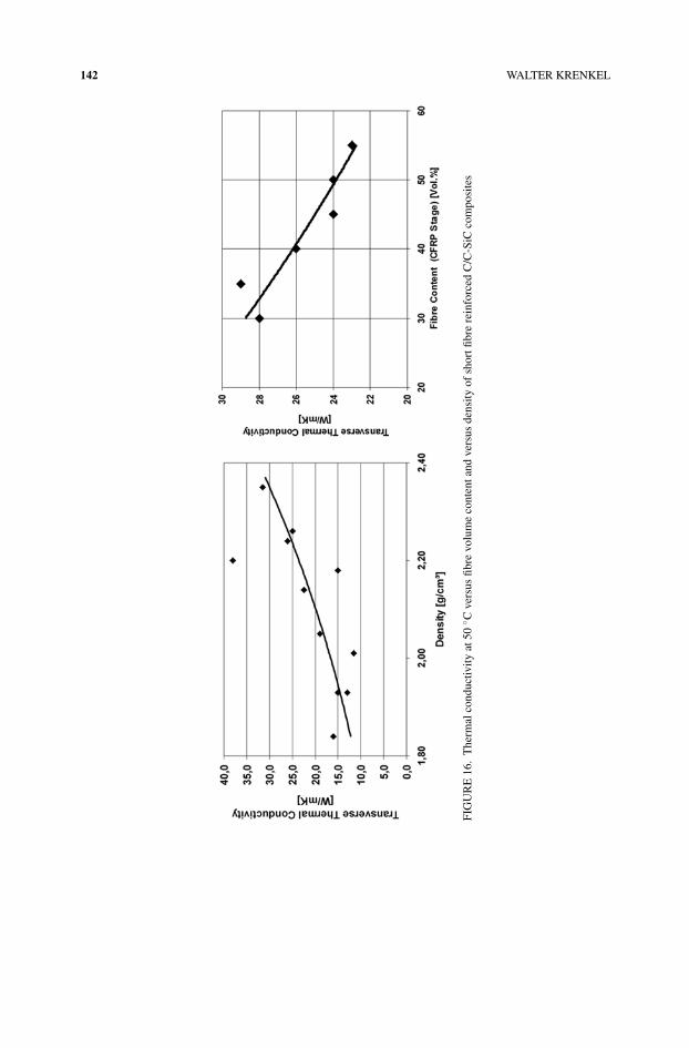
142 WALTER KRENKEL
FIG
UR
E16
.T
herm
alco
nduc
tivity
at50
◦ Cve
rsus
fibre
volu
me
cont
enta
ndve
rsus
dens
ityof
shor
tfibr
ere
info
rced
C/C
-SiC
com
posi
tes
CARBON FIBRE REINFORCED SILICON CARBIDE COMPOSITES 143
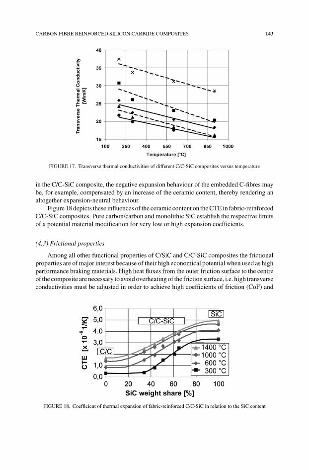
FIGURE 17. Transverse thermal conductivities of different C/C-SiC composites versus temperature
in the C/C-SiC composite, the negative expansion behaviour of the embedded C-fibres maybe, for example, compensated by an increase of the ceramic content, thereby rendering analtogether expansion-neutral behaviour.
Figure 18 depicts these influences of the ceramic content on the CTE in fabric-reinforcedC/C-SiC composites. Pure carbon/carbon and monolithic SiC establish the respective limitsof a potential material modification for very low or high expansion coefficients.
(4.3) Frictional properties
Among all other functional properties of C/SiC and C/C-SiC composites the frictionalproperties are of major interest because of their high economical potential when used as highperformance braking materials. High heat fluxes from the outer friction surface to the centreof the composite are necessary to avoid overheating of the friction surface, i.e. high transverseconductivities must be adjusted in order to achieve high coefficients of friction (CoF) and
FIGURE 18. Coefficient of thermal expansion of fabric-reinforced C/C-SiC in relation to the SiC content
144 WALTER KRENKEL
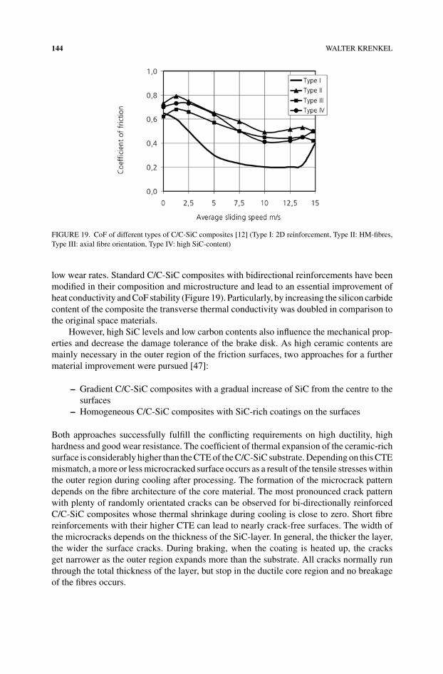
FIGURE 19. CoF of different types of C/C-SiC composites [12] (Type I: 2D reinforcement, Type II: HM-fibres,Type III: axial fibre orientation, Type IV: high SiC-content)
low wear rates. Standard C/C-SiC composites with bidirectional reinforcements have beenmodified in their composition and microstructure and lead to an essential improvement ofheat conductivity and CoF stability (Figure 19). Particularly, by increasing the silicon carbidecontent of the composite the transverse thermal conductivity was doubled in comparison tothe original space materials.
However, high SiC levels and low carbon contents also influence the mechanical prop-erties and decrease the damage tolerance of the brake disk. As high ceramic contents aremainly necessary in the outer region of the friction surfaces, two approaches for a furthermaterial improvement were pursued [47]:
– Gradient C/C-SiC composites with a gradual increase of SiC from the centre to thesurfaces
– Homogeneous C/C-SiC composites with SiC-rich coatings on the surfaces
Both approaches successfully fulfill the conflicting requirements on high ductility, highhardness and good wear resistance. The coefficient of thermal expansion of the ceramic-richsurface is considerably higher than the CTE of the C/C-SiC substrate. Depending on this CTEmismatch, a more or less microcracked surface occurs as a result of the tensile stresses withinthe outer region during cooling after processing. The formation of the microcrack patterndepends on the fibre architecture of the core material. The most pronounced crack patternwith plenty of randomly orientated cracks can be observed for bi-directionally reinforcedC/C-SiC composites whose thermal shrinkage during cooling is close to zero. Short fibrereinforcements with their higher CTE can lead to nearly crack-free surfaces. The width ofthe microcracks depends on the thickness of the SiC-layer. In general, the thicker the layer,the wider the surface cracks. During braking, when the coating is heated up, the cracksget narrower as the outer region expands more than the substrate. All cracks normally runthrough the total thickness of the layer, but stop in the ductile core region and no breakageof the fibres occurs.
CARBON FIBRE REINFORCED SILICON CARBIDE COMPOSITES 145
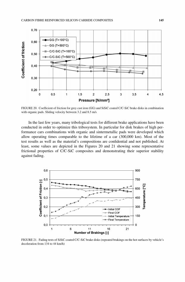
FIGURE 20. Coefficient of friction for grey cast iron (GG) and SiSiC coated C/C-SiC brake disks in combinationwith organic pads. Sliding velocity between 3.2 and 8.5 m/s
In the last few years, many tribological tests for different brake applications have beenconducted in order to optimize this tribosystem. In particular for disk brakes of high per-formance cars combinations with organic and sintermetallic pads were developed whichallow operating times comparable to the lifetime of a car (300,000 km). Most of thetest results as well as the material’s compositions are confidential and not published. Atleast, some values are depicted in the Figures 20 and 21 showing some representativefrictional properties of C/C-SiC composites and demonstrating their superior stabilityagainst fading.
FIGURE 21. Fading tests of SiSiC coated C/C-SiC brake disks (repeated brakings on the hot surfaces by vehicle’sdeceleration from 134 to 44 km/h)
146 WALTER KRENKEL
SUMMARY
Originally, the demands in space technology played the decisive role in the devel-opment of carbon fibre reinforced silicon carbide composites (C/SiC, C/C-SiC). Highmass-specific characteristics and extreme temperature resistance are important selectioncriteria for materials used in jet engines and thermal protection systems of new space-craft and rockets. Within the last few years, the properties and the manufacturing methodswere consistently improved, so that now also the industry in general can share in the prof-its of this new class of materials. The liquid silicon infiltration (LSI) process is regardedas the most promising process for industrial products, especially if the aspect of costs isconsidered.
C-fibre reinforced SiC composites differ widely in their microstructures and properties,depending on the applied processing method. Typically, their matrix is microporous andmicrocracked with a considerably heterogeneous structure. The microstructures can betailored by different methods, e.g. fibre coatings, fibre surface preparations or variations ofthe fibre alignment covering the whole range from nearly dense to fairly graded composites.In particular, C/C-SiC composites show superior tribological properties in comparison togrey cast iron or carbon/carbon. In combination with their low density, high thermal shockresistance and good abrasive resistance, these CMCs are promising candidates for advancedbrake and clutch systems. High improvements in wear resistance were achieved by SiSiCcoatings. Almost wear-free brake disks in combination with acceptable low wear rates forpads show a high potential for lifetime brake disks in passenger cars.
The utilization of C/SiC and C/C-SiC materials has been expanded to also cover quitedifferent fields of lightweight constructions, such as casings and construction elements foroptical systems, charging devices for heat treatment, calibrating plates or lightweight armorfor ballistic protection.
Due to the beginning industrialization of the manufacturing processes, which has juststarted out, the designers and also the users are lacking practical experience with this newstructural ceramic material. Design rules, as have been developed for other composite ma-terials, metals or ceramics without reinforcement, are only available in limited extent untilnow. This will, however, change in the near future, if one succeed in making full use ofthe production capacities built up so far, and in gaining a broad basic knowledge as well asapplication-specific experience.
Until now, low empirical information has been gained regarding the production ofC/C-SiC components in larger quantities. The manufactured quantities are still modest(approximately 10,000 parts per year), and they are burdened with high specific component-costs of about 250 Dollar/kg. The growth of production facilities among several manufac-turers and cost-reducing technologies are measures already being applied, which allowconsiderably lower material costs to be anticipated for the future.
REFERENCES
1. G. Savage, Carbon/Carbon Composites, Chapman & Hall (1993).2. V. I. Trefilov, Ceramic- and Carbon-Matrix Composites, Chapman & Hall (1995).3. K. K. Chawla, Ceramic Matrix Composites, Chapman & Hall (1993).
CARBON FIBRE REINFORCED SILICON CARBIDE COMPOSITES 147
4. D. B. Fischbach and D. R. Uptegrove, in Proceedings of 13th Biennial Confernce on Carbon (1977).5. R. Weiss, Carbon Fibre Reinforced CMCs: Manufacture, Properties, Oxidation Protection, High Temperature
Ceramic Matrix Composites (Eds.: W. Krenkel, R. Naslain, H. Schneider), WILEY-VCH, Weinheim, Germany,(2001), p. 440–456.
6. A. Muhlratzer and M. Leuchs, Applications of Non-Oxide CMCs, High Temperature Ceramic MatrixComposites (Eds.: W. Krenkel, R. Naslain, H. Schneider), WILEY-VCH, Weinheim, Germany (2001),p. 288–298.
7. H. Hald, H. Weihs, B. Benitsch, I. Fischer, T. Reimer, P. Winkelmann and A. Gulhan, Development of a NoseCap System for X-38, in Proceedings of International Symposium Atmospheric Reentry Vehicles and Systems,Arcachon, France (1999).
8. U. Trabandt and W. Fischer, in Proceedins of the Int. Congress on Environmental Systems, Orlando, FL, USA,paper 01-ICES-184 (2001).
9. W. Schafer and W. D. Vogel, Faserverstarkte Keramiken hergestellt durch Polymerinfiltration, KeramischeVerbundwerkstoffe (Ed.: W. Krenkel), WILEY-VCH, Weinheim, Germany (2003), p. 76–94.
10. F. Christin, Design, Fabrication and Application of Thermostructural Composites (TSC) like C/C, C/SiC andSiC/SiC Composites, Advanced Engineering Materials, 4, No. 12 (2002), p. 903–912.
11. W. Krenkel, CMC Materials for High Performance Brakes, in Proceedings ISATA Conference on Supercars,Aachen (1994).
12. W. Krenkel, B. Heidenreich and R. Renz, C/C-SiC Composites for Advanced Friction Systems, AdvancedEngineering Materials 4, No. 7 (2002) p. 427–436.
13. S. Vaidyaraman, M. Purdy, T. Walker and S. Horst, C/SiC Material Evaluation for Aircraft Brake Applications,High Temperature Ceramic Matrix Composites (Eds.: W. Krenkel, R. Naslain, H. Schneider), WILEY-VCH,Weinheim, Germany (2001), p. 802–808.
14. M. Krupka and A. Kienzle, Fiber Reinforced Ceramic Composites for Brake Discs, SAE Technical PaperSeries 2000-01-2761 (2000).
15. R. Gadow and M. Speicher, Manufacturing of Ceramic Matrix Composites for Automotive Applications,Ceramic Transactions Vol. 128 (2001), p. 25–41.
16. Z. Rak, CF/SiC/C Composites for Tribological Application, High Temperature Ceramic Matrix Compos-ites (Eds.: W. Krenkel, R. Naslain, H. Schneider), WILEY-VCH, Weinheim, Germany (2001), p. 820–825.
17. R. Renz, W. Krenkel, C/C-SiC Composites for High Performance Emergency Brake Systems, in Proceedingsof 9th European Conference on Composite Materials (ECCM-9), Brighton, UK (2000).
18. B. Heidenreich, R. Renz and W. Krenkel, Short Fibre Reinforced CMC Materials for High Performance Brakes,High Temperature Ceramic Matrix Composites (Eds.: W. Krenkel, R. Naslain, H. Schneider), WILEY-VCH,Weinheim, Germany (2001), p. 809–815.
19. R. Kochendorfer and N. Lutzenburger, Applications of CMCs made via the Liquid Silicon Infiltration (LSI)Technique, High Temperature Ceramic Matrix Composites (Eds.: W. Krenkel, R. Naslain, H. Schneider),WILEY-VCH, Weinheim, Germany (2001), p. 277–287.
20. R. Renz, B. Heidenreich, W. Krenkel, A. Schoppach and F. Richter, CMC Materials for Lightweight andlow CTE Applications, High Temperature Ceramic Matrix Composites (Eds.: W. Krenkel, R. Naslain, H.Schneider), WILEY-VCH, Weinheim, Germany (2001), p. 839–845.
21. J. Schmidt, M. Scheiffele and W. Krenkel, Engineering of CMC Tubular Components, High TemperatureCeramic Matrix Composites (Eds.: W. Krenkel, R. Naslain, H. Schneider), WILEY-VCH, Weinheim, Germany(2001), p. 826–831.
22. M. Labanti, G. Martignani, C. Mingazzini, G. L. Minoccari, L. Pilotti, A. Ricci and R. Weiss, Evaluation ofDamage by Oxidation Corrosion at High Temperatures of Coated C/C-SiC Ceramic Composite, High Tem-perature Ceramic Matrix Composites (Eds.: W. Krenkel, R. Naslain, H. Schneider), WILEY-VCH, Weinheim,Germany (2001), p. 218–223.
23. ECM, Cesic R© Kohlefaserverstrktes Siliciumcarbid, Produktinformation.24. B. Heidenreich, W. Krenkel and B. Lexow, Development of CMC-Materials for Lightweight Armor, in
Ceram. Eng. Sci. Proc., 24 [3] (2003), p. 375–381.25. R. Naslain and F. Langlais, CVD Processing of Ceramic-Ceramic Composites Materials, Mat. Science
Research, Vol. 20, Plenum Press New York (1985), p. 145–164.26. D. P. Stinton, A. J. Caputo and R. A. Lowden, Synthesis of Fibre-Reinforced SiC Composites by Chemical
Vapour Infiltration, J. Amer. Ceram. Society Bulletin, Vol. 65, No 2 (1986), p. 347.

148 WALTER KRENKEL
27. M. Leuchs and A. Muhlratzer, CVI-Verfahren zur Herstellung faserverstrkter Keramik – Herstellung,Eigenschaften, Anwendungen, Keramische Verbundwerkstoffe (Ed.: W. Krenkel), WILEY-VCH, Weinheim,Germany (2003), p. 95–121.
28. R. J. Diefendorf and R. P. Boisvert, Siliciumcarbid-Composites durch polymere Ausgangsstoffe, in Proceedingsof Verbundwerk 1988, Demat Exposition Managing, Frankfurt, Germany (1988), p. 13.01–13.37.
29. T. Haug, R. Ostertag and W. Schfer, Fiber Reinforced Ceramics for Aerospace Applications, Advanced Materi-als and Structures from Research to Application (Eds.: J. Brandt, H. Hornfeld, M. Neitzel), SAMPE EuropeanChapter (1992), p. 163–173.
30. A. Muhlratzer, K. Handrick and H. Pfeiffer, Acta Astronautica, 42 (1998), p. 533–540.31. C. C. Evans, A. C. Parmee and R. W. Rainbow, Silicon Treatment of Carbon Fiber-Carbon Composites, in
Proceedings of 4th London Conference on Carbon and Graphite (1974), p. 231–235.32. W. B. Hillig, R. L. Mehan, C. R. Morelock, V. I. DeCarlo and W. Laskow, Silicon/Silicon Carbide Composites,
Ceramic Bulletin, Vol. 54, No. 12 (1975).33. R. Gadow, Die Silizierung von Kohlenstoff, Doctoral Thesis, University of Karlsruhe (1986).34. W. Krenkel, Development of a Cost Efficient Process for the Manufacture of CMC Components, Doctoral
Thesis, University of Stuttgart, DLR-Forschungsbericht 2000–4 (2000).35. W. Krenkel, Cost Effective Processing of CMC Composites by Melt Infiltration (LSI-Process), Ceramic
Engineering and Science Proceedings (Ed: American Ceramic Society), Vol. 22, Issue 3 (2001), p. 443–454.36. W. Krenkel and H. Hald, Liquid Infiltrated C/SiC – An Alternative Material for Hot Space Structures in
Spacecraft Structures and Mechanical Testing, European Space Agency Publications Division, Paris, France,ESA SP-289 (1989), p. 325.
37. R. Kochendorfer and W. Krenkel, CMC Intake Ramp for Hypersonic Propulsion Systems, High-TemperatureCeramic-Matrix Composites I: Design, Durability and Performance (Eds.: A. G. Evans, R. Naslain), CeramicTransactions, Vol. 57 (1995), p. 13–22.
38. J. Schulte-Fischedick, A. Zern, J. Mayer, M. Ruhle, M. Frieß, W. Krenkel and R. Kochendorfer, TheMorphology of Silicon Carbide in C/C-SiC Composites, Journal of Material Science and Engineering A,Elsevier Science B.V. (2002), p. 146–152.
39. W. Krenkel, R. Renz and B. Heidenreich, Lightweight and Wear Resistant CMC Brakes, Ceramic Materialsand Components for Engines (Eds.: J. G. Heinrich, F. Aldinger), WILEY-VCH, Weinheim, Germany (2001),p. 63–67.
40. C. A. Nannetti, A. Borello and D. A. de Pinto, C-Fiber Reinforced Ceramic Matrix Composites by a Com-bination of CVI, PIP and RB, High Temperature Ceramic Matrix Composites (Eds.: W. Krenkel, R. Naslain,H. Schneider), WILEY-VCH, Weinheim, Germany (2001), p. 368–374.
41. M. Frieß and W. Krenkel, Silicon Based Preceramic Polymers in Combination With the LSI-Process inProceedings of Materials Week 2000, International Congress on Advanced Materials their Processes andApplications, Munich, Germany (2002).
42. A. Muhlratzer, Production, Properties and Applications of Ceramic Matrix Composites, CFI/Ber. DKG 76,No. 4 (1999), p. 30–35.
43. D. Desnoyer, A. Lacombe and J. M. Rouges, Large Thin Composite Thermo-structural Parts in Proceed-ings of Intern. Conference “Spacecraft Structures and Mechanical Testing”, Noordwijk/Netherlands, (1991),ESA/ESTEC.
44. Data sheet from GE Power Systems, Engineering Data of Power Systems Composites, LCC, Newark, Delaware,(2003).
45. W. Krenkel, Designing with C/C-SiC Composites, in Advances in Ceramic Matrix Composites IX (Eds.: N.P.Bansal, J.P. Singh, W.K. Kriven, H. Schneider), Ceram. Trans., 153 (2003), p. 103–123.
46. Data sheet from SGL Carbon Group, SIGRASIC 6010 GNJ – Faserverstarkte Keramik fur Bremsscheiben(1998).
47. W. Krenkel, C/C-SiC Composites for Hot Structures and Advanced Friction Systems in Ceram. Eng. Sci.Proc., 24 [4] (2003), p. 583–592.


![A Review on Natural Fibre Reinforced Polymer Composites · natural fibre reinforced polymer composites increase with increasing fibre loading. Khoathane et al. [1] found that the](https://img.pdfslide.us/doc/110x75/5e21837fc2d50e18910e61ca/a-review-on-natural-fibre-reinforced-polymer-composites-natural-fibre-reinforced.jpg)