Embed Size (px)
Citation preview
PROJECTE O TESINA D’ESPECIALITAT
Títol
Use of Fibre Reinforced Polymer Composites in Bridge
Construction. State of the Art in Hybrid and All-Composite
Structures.
Autor/a
Paweł Bernard Potyrała
Tutor/a
Joan Ramón Casas Rius
Departament
Enginyeria de la Construcció
Intensificació
Construcció
Data
Juny 2011
Use of Fibre Reinforced Polymer Composites in Bridge Construction. State of the Art in Hybrid and All-Composite Structures.
2
SUMMARY
Title: Use of Fibre Reinforced Polymers in Bridge Construction. State of the
Art in Hybrid and All-Composite Structures.
Autor: Paweł Bernard Potyrała
Tutor: Joan Ramón Casas Rius
Keywords: modern materials, FRP composites, fibres, polymers, GFRP, CFRP,
all-composite bridge structures, hybrid bridge structures
Fibre reinforced polymer composites, developed primarily for the aerospace and
defence industries, are a class of materials with great potential to use in civil
infrastructure. Since the construction of the first all-composite bridge superstructure in
Miyun, China, in 1982, they have been gradually gaining acceptance from civil
engineers as a new construction material. During these 30 years, their proved to be
useful in a few areas of application: mostly in form of sheets and strips for
strengthening existing bridge structures, and to some extent, as reinforcing bars
substituting steel as concrete reinforcement.
Also, a number of constructions have built, in which FRP composites replaced
traditional materials for structural elements (girders, bridge decks, stay cables). Among
these constructions there is a relatively big amount of hybrid bridge structures, where
only a part of the superstructure is made of FRP composites, and a much smaller
amount of all-composite bridge structures, with superstructures made exclusively of this
material.
The purpose of this paper is to present the state of the art in the use of FRP
composites in bridge engineering with the focus on hybrid and all-composite structures.
Firstly, the paper will present the basic information about FRP composites,
including the definition, description of the components, mechanical properties and
general areas of application. Then, it will focus on FRP composites as the material of
which structural elements are made, describing manufacturing processes relevant to
civil engineering applications, assortment of structural profiles, cables, tendons and
bridge deck systems, presenting the problem of codes and design guidelines that refer to
the use FRP composites as the construction material, and methods of joining structural
elements. Thirdly, it will compare the properties of FRP composites with those of
traditional materials. Finally, there are presented some examples of hybrid and all-
composite bridge structures and a list of 355 constructions made of this material around
the world, with basic data and references providing more information.

Use of Fibre Reinforced Polymer Composites in Bridge Construction. State of the Art in Hybrid and All-Composite Structures.
3
CONTENTS
0. Introduction and objectives………………………………….…………… 5
1. Introduction to the material. Definition…………………………..……… 6
2. Components………………………………………………………….…… 6
2.1.Fibres………………………………………………………………...…… 6
2.1.1. Definition and function………………………………………….…… 6
2.1.2. Forms of fibres…………………………………………………..…… 6
2.1.3. Types of fibres…………………………………………………...…… 8
2.1.3.1.Glass fibres…………………………………………………………… 8
2.1.3.2.Carbon fibres………………………………………………….……… 9
2.1.3.3.Aramid fibres………………………………………………….……… 10
2.2.Matrix……………………………………………………………..……… 10
2.2.1. Definition and function………………………………………….…… 10
2.2.2. Components of matrix………………………………………...……… 11
2.2.2.1.Resins………………………………………………………….……… 11
2.2.2.2.Fillers………………………………………………………….……… 12
2.2.2.3.Additives……………………………………………………………… 12
2.3.Fibre-Matrix bonding………………………………………………...…… 12
3. Mechanical properties………………………………………………..…… 13
3.1.Density…………………………………………………………….……… 13
3.2.Modulus………………………………………………………………...… 14
3.3.Poisson's ratio………………………………………………………..…… 15
3.4.Stress-strain relationship and tensile strength…………………………..…16
4. Areas of application…………………………………………………….… 18
4.1.Repair and Retrofitting of Existing Bridge Structures…………………… 18
4.2.Reinforcement of concrete………………………………………...……… 18
4.3.Hybrid Bridge Structures………………………………………………… 19
4.4.All-Composite Bridge Structures………………………………………… 20
5. Manufacturing………………………………………………………..…… 22
5.1.Choosing the method………………………………………………...…… 22
5.2.Manual and semi-automated methods…………………………….……… 22
5.3.Fully-automated methods………………………………………………… 23
5.3.1. Pultrusion………………………………………………………...…… 23
5.3.2. Filament winding…………………………………………………...… 25
5.3.3. Resin transfer moulding…………………………………………….… 25
6. Assortment of FRP composite elements used in bridge engineering…..… 26
6.1.Structural profiles………………………………………………………… 26
6.2.Cables and tendons……………………………………………………..… 28
6.3.Decks…………………………………………………………………...… 28
7. Codes and Design Guidelines: current status………………………..…… 29
Use of Fibre Reinforced Polymer Composites in Bridge Construction. State of the Art in Hybrid and All-Composite Structures.
4
7.1.Codes………………………………………………………………...…… 29
7.2.Guidelines………………………………………………………………… 31
8. Connections……………………………………………………….……… 31
8.1.General information……………………………………………….……… 31
8.2.Bonded connections……………………………………………………… 32
8.3.Mechanical connections……………………………………………...…… 34
8.4.Combined connections…………………………………………….……… 35
8.5.Comparison………………………………………………………..……… 36
9. Comparison to conventional construction materials……………………… 38
9.1.Advantages over traditional materials……………………………….…… 38
9.1.1. High Specific Strength and Stiffness………………………………… 38
9.1.2. Corrosion resistance…………………………………………………... 41
9.1.3. Enhanced Fatigue Life……………………………………………… 41
9.1.4. Quick and easy transport and installation…………………………… 42
9.1.5. Tailored properties…………………………………………………… 43
9.1.6. Sustainability – effects on environment……………………………… 43
9.1.7. Electromagnetic transparency………………………………………… 44
9.1.8. Aesthetics and dimensional stability……………………….………… 44
9.1.9. Resistance to frost and de-icing salt………………………………..… 44
9.2.Disadvantages………………………………………………………..…… 44
9.2.1. Higher short-term and uncertain long-term costs…………………..… 44
9.2.2. Uncertain durability……………………………………………...…… 45
9.2.3. Lack of ductility…………………………………………………....… 45
9.2.4. Low fire resistance……………………………………………….…… 46
9.2.5. Lack of Design Standards………………………………………..…… 46
9.2.6. Lack of Knowledge on Connections…………………………….…… 46
10. Examples of Hybrid Bridge Structures………………………………....… 47
10.1. Footbridge over road no. 11 in Gądki………………………..…… 47
10.2. Kings Stormwater Channel Bridge…………………………..…… 49
10.3. Friedberg Bridge over B3 Highway………………………….…… 51
11. Examples of All-Composite Bridge Structures………………………...… 53
11.1. West Mill Bridge……………………………………………..…… 53
11.2. ApATeCh arched footbridge………………………………....…… 55
11.3. Lleida footbridge……………………………………………..…… 56
11.4. Aberfeldy footbridge……………………………………….……...58
12. List of bridges with FRP composite components………………………… 61
13. Conclusions…………………………………………………………..……91
14. Literature……………………………………………………………….… 92
Use of Fibre Reinforced Polymer Composites in Bridge Construction. State of the Art in Hybrid and All-Composite Structures.
5
0. Introduction and objectives
The aim of this paper is to present FRP composites as the new material used for
the purposes of civil engineering and prepare the state of the art in bridge structures
using FRP composites for structural elements as the substitution of traditional materials.
The body of the project consists of 12 chapters: five of them focusing on the description
of the material and general application areas in bridge engineering, and the rest - on
issues referring to two particular uses: hybrid and all-composite bridge structures.
Chapter one gives a general idea on FRP composite, defines it as a construction
material and compares it to similarly working traditional materials.
Chapter two focuses on the components of FRP composite, presents various
kinds of fibres used as reinforcement and compares their properties. It describes the
ingredients of a matrix: resins, fillers and additives, as well as the importance of fibre-
matrix bond.
Chapter three lists a number of properties of FRP composites common for these
kind of materials and then presents some of them, such as density, modulus, Poisson´s
ratio and tensile strength with more details, giving simplified formulas to determine
their values basing on the properties of the components.
Chapter four briefly describes general areas of application of FRP composites in
bridge engineering: repair and retrofitting of existing bridge structures, concrete
reinforcement, hybrid bridge structures and all-composite bridge structures.
Chapter five focuses on manufacturing methods relevant to civil engineering
applications, dividing them into manual, semi-automated and automated processes. Of
special interest is the pultrusion process, which provides the possibility to produce FRP
composite elements on a bigger scale.
Chapter six presents the assortment of structural profiles, cables/tendons and
bridge decks made of FRP composites, produced by various companies around the
world.
Chapter seven gives a brief explanation of current status of codes and design
guidelines referring to the use FRP composites as the construction material.
Chapter eight presents and compares various kinds of connections between FRP
composite elements: adhesive, mechanical and mixed.
Chapter nine compares FRP composites to traditional materials, presenting their
advantages and disadvantages (uncertainties).
Chapter ten and eleven present some examples of existing, representative hybrid
and all-composite bridge structures, respectively. Chosen examples are constructions
varying in structural type, year of construction and FRP composite system used.
Finally, chapter twelve presents a list of 355 FRP-using bridges, specifying the
name of the structure, location, year of assembly and some basic available data, usually
including the length and width of the bridge and the manufacturing company, as well as
references providing more information (articles, photos, additional data, etc.).
Use of Fibre Reinforced Polymer Composites in Bridge Construction. State of the Art in Hybrid and All-Composite Structures.
6
1. Introduction to the material. Definition.
Composite is defined as a mechanically separable combination of two or more
component materials, different at the molecular level, mixed purposefully in order to
obtain a new material with optimal properties, different than the properties of the
components (definition based on [1], [2], [3]).
Composite materials have been used in construction for centuries. One of the
first was the use of straw as reinforcement in mud and clay bricks by the ancient
Egyptians [4]. The combination of reinforcing steel and concrete has been the basis for
a number of structural systems used for construction for the last century. The new class
of composite materials, gradually gaining acceptance from civil engineers, both for the
rehabilitation of existing structures and for the construction of new facilities, are Fibre
Reinforced Polymer composites, primarily developed for the aerospace and defence
structures.
Fibre Reinforced Polymer composites are the combination of polymeric resins,
acting as matrices or binders, with strong and stiff fibre assemblies which act as the
reinforcing phase [2]. The combination of the matrix phase with a reinforcing phase
produces a new material system, analogous to steel reinforced concrete, although the
reinforcing fractions vary considerably (i.e., reinforced concrete in general rarely
contains more than 5% reinforcement, whereas in FRP composites, according to various
sources ([1] - [5]), reinforcing volume fraction ranges from 30-70%).
2. Components
2.1.Fibres
2.1.1. Definition and function
A fibre is a material made into a long filament. According to [5], a single fibre
usually has a diameter up to 15 um. Bigger diameters generally increase the probability
of surface defects. The aspect ratio of length and diameter can be ranging from thousand
to infinity in continuous fibres. They usually occupy 30-70% of the volume of the
composite and 50% of its weight.
The main functions of fibres are to carry the load and provide stiffness, strength,
thermal stability and other structural properties to the FRP [2]. To perform these
functions, the fibres in FRP composite must have high modulus of elasticity, high
ultimate strength, low variation of strength among fibres, high stability of their strength
during handling and high uniformity of diameter and surface dimension among fibres.
2.1.2. Forms of fibres
There are various forms of fibres used as a reinforcement of polymer
composites. Manufacturers of structural elements made of FRP composites usually
present the variety of reinforcement techniques in specifications/design guides (for
Use of Fibre Reinforced Polymer Composites in Bridge Construction. State of the Art in Hybrid and All-Composite Structures.
7
instance, Fiberline Composites in [6]). Basically, there are two forms of reinforcement:
rovings and fabrics [5].
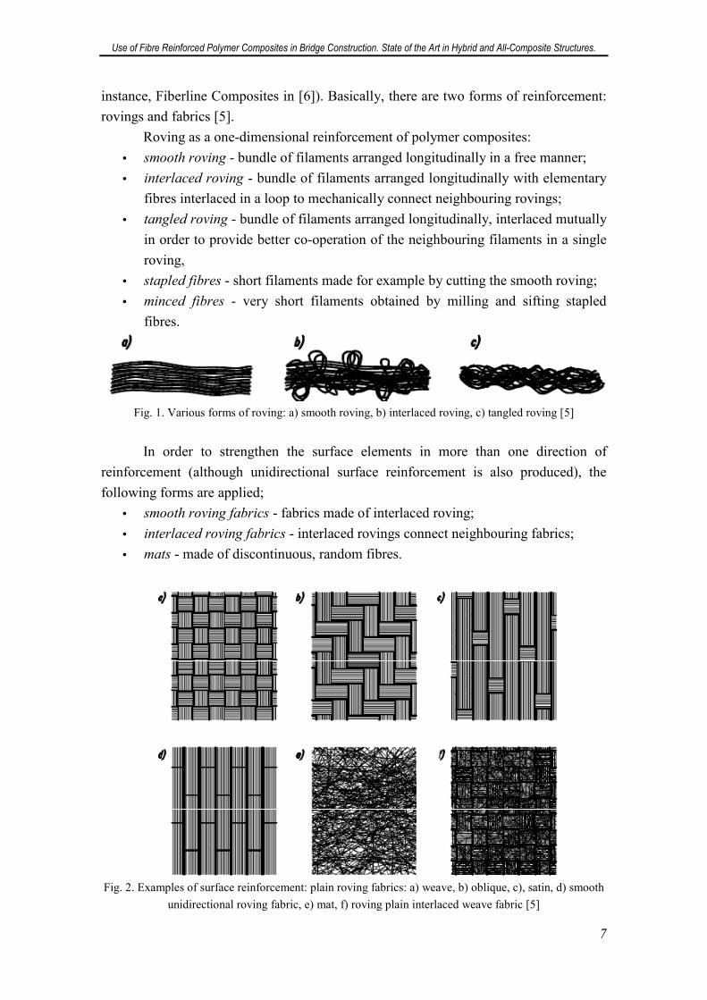
Roving as a one-dimensional reinforcement of polymer composites:
• smooth roving - bundle of filaments arranged longitudinally in a free manner;
• interlaced roving - bundle of filaments arranged longitudinally with elementary
fibres interlaced in a loop to mechanically connect neighbouring rovings;
• tangled roving - bundle of filaments arranged longitudinally, interlaced mutually
in order to provide better co-operation of the neighbouring filaments in a single
roving,
• stapled fibres - short filaments made for example by cutting the smooth roving;
• minced fibres - very short filaments obtained by milling and sifting stapled
fibres.
Fig. 1. Various forms of roving: a) smooth roving, b) interlaced roving, c) tangled roving [5]
In order to strengthen the surface elements in more than one direction of
reinforcement (although unidirectional surface reinforcement is also produced), the
following forms are applied;
• smooth roving fabrics - fabrics made of interlaced roving;
• interlaced roving fabrics - interlaced rovings connect neighbouring fabrics;
• mats - made of discontinuous, random fibres.
Fig. 2. Examples of surface reinforcement: plain roving fabrics: a) weave, b) oblique, c), satin, d) smooth
unidirectional roving fabric, e) mat, f) roving plain interlaced weave fabric [5]
Use of Fibre Reinforced Polymer Composites in Bridge Construction. State of the Art in Hybrid and All-Composite Structures.
8
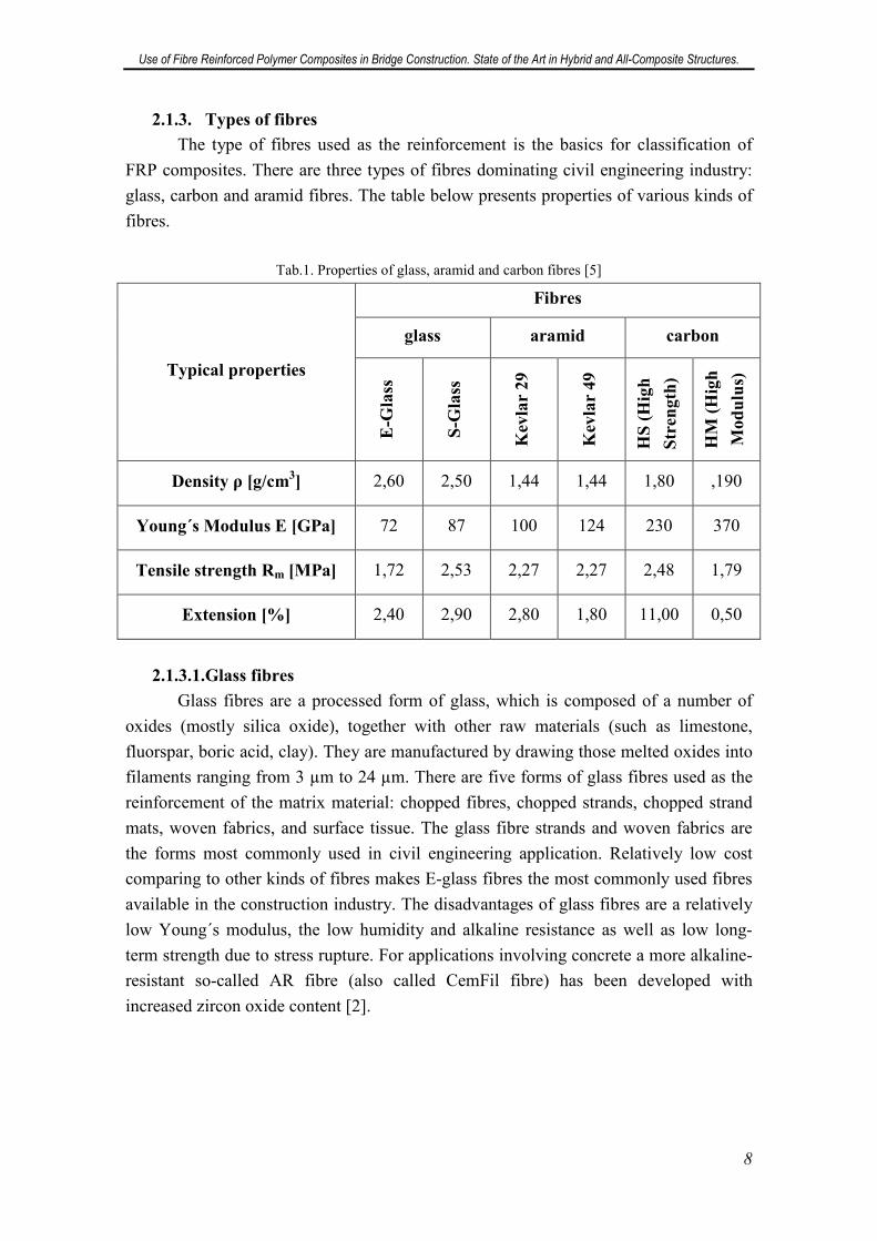
2.1.3. Types of fibres
The type of fibres used as the reinforcement is the basics for classification of
FRP composites. There are three types of fibres dominating civil engineering industry:
glass, carbon and aramid fibres. The table below presents properties of various kinds of
fibres.
Tab.1. Properties of glass, aramid and carbon fibres [5]
Typical properties
Fibres
glass aramid carbon
E-G
lass
S-G
lass
Kev
lar
29
Kev
lar
49
HS
(H
igh
Str
eng
th)
HM
(H
igh
Mo
du
lus)
Density ρ [g/cm3] 2,60 2,50 1,44 1,44 1,80 ,190
Young´s Modulus E [GPa] 72 87 100 124 230 370
Tensile strength Rm [MPa] 1,72 2,53 2,27 2,27 2,48 1,79
Extension [%] 2,40 2,90 2,80 1,80 11,00 0,50
2.1.3.1.Glass fibres
Glass fibres are a processed form of glass, which is composed of a number of
oxides (mostly silica oxide), together with other raw materials (such as limestone,
fluorspar, boric acid, clay). They are manufactured by drawing those melted oxides into
filaments ranging from 3 µm to 24 µm. There are five forms of glass fibres used as the
reinforcement of the matrix material: chopped fibres, chopped strands, chopped strand
mats, woven fabrics, and surface tissue. The glass fibre strands and woven fabrics are
the forms most commonly used in civil engineering application. Relatively low cost
comparing to other kinds of fibres makes E-glass fibres the most commonly used fibres
available in the construction industry. The disadvantages of glass fibres are a relatively
low Young´s modulus, the low humidity and alkaline resistance as well as low long-
term strength due to stress rupture. For applications involving concrete a more alkaline-
resistant so-called AR fibre (also called CemFil fibre) has been developed with
increased zircon oxide content [2].
Use of Fibre Reinforced Polymer Composites in Bridge Construction. State of the Art in Hybrid and All-Composite Structures.
9
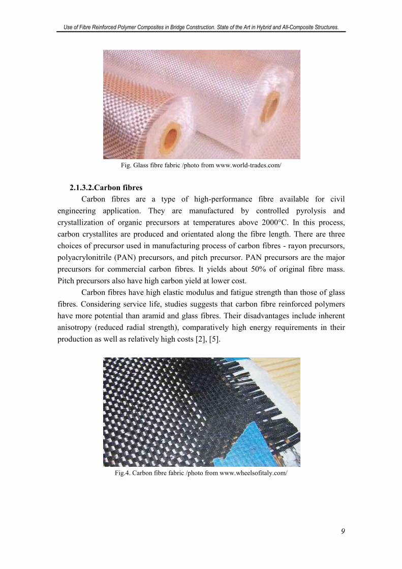
Fig. Glass fibre fabric /photo from www.world-trades.com/
2.1.3.2.Carbon fibres
Carbon fibres are a type of high-performance fibre available for civil
engineering application. They are manufactured by controlled pyrolysis and
crystallization of organic precursors at temperatures above 2000°C. In this process,
carbon crystallites are produced and orientated along the fibre length. There are three
choices of precursor used in manufacturing process of carbon fibres - rayon precursors,
polyacrylonitrile (PAN) precursors, and pitch precursor. PAN precursors are the major
precursors for commercial carbon fibres. It yields about 50% of original fibre mass.
Pitch precursors also have high carbon yield at lower cost.
Carbon fibres have high elastic modulus and fatigue strength than those of glass
fibres. Considering service life, studies suggests that carbon fibre reinforced polymers
have more potential than aramid and glass fibres. Their disadvantages include inherent
anisotropy (reduced radial strength), comparatively high energy requirements in their
production as well as relatively high costs [2], [5].
Fig.4. Carbon fibre fabric /photo from www.wheelsofitaly.com/
Use of Fibre Reinforced Polymer Composites in Bridge Construction. State of the Art in Hybrid and All-Composite Structures.
10
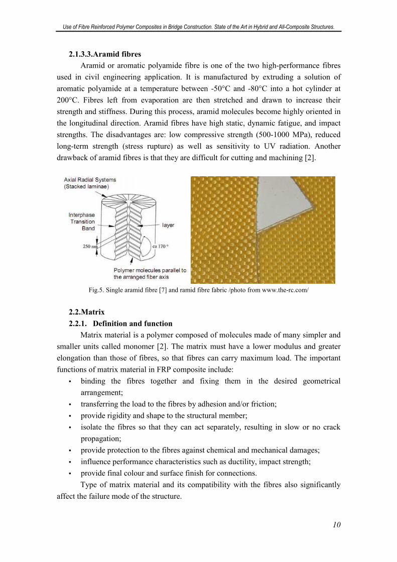
2.1.3.3.Aramid fibres
Aramid or aromatic polyamide fibre is one of the two high-performance fibres
used in civil engineering application. It is manufactured by extruding a solution of
aromatic polyamide at a temperature between -50°C and -80°C into a hot cylinder at
200°C. Fibres left from evaporation are then stretched and drawn to increase their
strength and stiffness. During this process, aramid molecules become highly oriented in
the longitudinal direction. Aramid fibres have high static, dynamic fatigue, and impact
strengths. The disadvantages are: low compressive strength (500-1000 MPa), reduced
long-term strength (stress rupture) as well as sensitivity to UV radiation. Another
drawback of aramid fibres is that they are difficult for cutting and machining [2].
Fig.5. Single aramid fibre [7] and ramid fibre fabric /photo from www.the-rc.com/
2.2.Matrix
2.2.1. Definition and function
Matrix material is a polymer composed of molecules made of many simpler and
smaller units called monomer [2]. The matrix must have a lower modulus and greater
elongation than those of fibres, so that fibres can carry maximum load. The important
functions of matrix material in FRP composite include:
• binding the fibres together and fixing them in the desired geometrical
arrangement;
• transferring the load to the fibres by adhesion and/or friction;
• provide rigidity and shape to the structural member;
• isolate the fibres so that they can act separately, resulting in slow or no crack
propagation;
• provide protection to the fibres against chemical and mechanical damages;
• influence performance characteristics such as ductility, impact strength;
• provide final colour and surface finish for connections.
Type of matrix material and its compatibility with the fibres also significantly
affect the failure mode of the structure.
Use of Fibre Reinforced Polymer Composites in Bridge Construction. State of the Art in Hybrid and All-Composite Structures.
11
2.2.2. Components of matrix
Matrix consists of resins, fillers and additives.
2.2.2.1.Resins
Resins are the main component of a matrix. Categorized by manufacturing
method and properties, two major types of resins are thermoplastic and thermosetting
polymers [5].
Thermoplastic polymers are ductile in nature and tougher than thermoset
polymers [2]. However, they have lower stiffness and strength. They can be reformed
and reshaped by simply heating and cooling. Since the molecules do not cross-link,
thermoplastics are flexible and deformable. They have poor creep resistance at high
temperature and more susceptible to solvent than thermosets. Commonly used
thermoplastics are nylon, polyetheretherketine (PEEK), polypropylene (PP), and
polyphenylene sulfide (PPS).
For FRP structures today mainly thermosetting polymers are used. They are
usually made from liquid or semi-solid precursors. These precursors harden in a series
of chemical reactions called polycondensation, polymerization, or curing. At the end of
manufacturing process, they are converted into hard solid, producing a tightly bound
three-dimensional network of polymer chain. Unlike thermoplastic polymers, once
thermosetting polymers are cured, they cannot be remelted or reformed. Thermosets are
usually brittle in nature. They offer high rigidity, thermal and dimensional stability,
higher electrical, chemical, and solvent resistance. The most important thermosets in use
are polyester resins, epoxy resins and phenol resins [6].
Polyester is the most frequently used matrix, as it gives a composite good all-
round properties. Unsaturated polyester can be divided into three main groups:
orthopolyester, isopolyester and vinylester. In relation to orthopolyester, isopolyester
increases impact resistance, provides greater flexibility, and increases resistance to
temperatures. It also increases corrosion resistance.
Vinylester has even better corrosion-resistant and thermal properties. Since
vinylester has greater elongation properties than ortho- and isopolyester, it also provides
a composite with better impact resistance and improved fatigue properties.
Epoxy is used primarily for carbon-reinforced profiles, giving composited better
fatigue and mechanical properties. Epoxy is more resistant to thermal influences and has
better electrical properties.
Phenol is used when there are requirements for high fire resistance, temperature
resistance, low smoke generation, and flame retardation when subjected to fire.
All types of resins are sensitive to UV radiation. Therefore, they require an
appropriate protection by means of special additives and/or surface fleeces [5].
Use of Fibre Reinforced Polymer Composites in Bridge Construction. State of the Art in Hybrid and All-Composite Structures.
12
2.2.2.2.Fillers
The function of fillers is to fill out the form of a profile in order to reduce the use
of more expensive reinforcement and matrix materials. They make it possible to reduce
the price of finished product [6].
Most popularly used fillers are inorganic materials such as calcium carbonate,
kaolinite and aluminium oxide [5].
2.2.2.3.Additives
Additives are constituent components that may be added to the composite matrix
to modify its properties and in general, enhance its performance. Additives include
catalysts, colorants, flame retardants and other ingredients that expand and improve the
capabilities of the matrix. Depending upon their purpose, additives can be divided into
two fundamental groups according to [6]: process-related additives and function-related
additives. While the purpose can vary, additives will always influence the corrosion
resistance of profiles, as well as their mechanical and fire resistance properties.
Process-related additives are substances with advantageous effect on the
manufacturing process, and on the properties and appearance of an element. An
example of this is a so-called low-profile additive used in pultrusion process, which is
used to avoid excessive shrinkage during curing of profiles. The additive prevents
formation of hair-line cracks in surfaces, while improving profile resistance to
corrosion, as well as improving fatigue properties. It also gives profiles more exact
geometric tolerances and lower internal stress.
Function-related additives have an advantageous effect in relation to the use of a
finished profile. An example of this is the adding of pigments or fire retardants. The
latter are added to obtain self-extinguishing properties and to retard flame spread. Of
course, function-related additives can also be added in amounts so large that they
degrade the mechanical properties of a profile.
2.3.Fibre-Matrix bonding
The mechanical properties of fibre-polymer bonds are mainly determined by the
adhesion and the mechanical compatibility between the fibres and the matrix as well as
the angle between the fibres and the direction of loading.
In order to obtain a good mechanical interaction between the fibres and the
matrix, their mechanical parameters must be adapted to each other. The approximately
linear-elastic deformational behaviour of the composite is governed primarily by the
reinforcing fibres. In order to prevent the development of microcracks in the matrix
before reaching the fibre’s elongation limit, the failure strain of the matrix should be
greater than that of the fibres. Under compression, however, a minimum stiffness of the
matrix is required to prevent buckling of the fibres.
Use of Fibre Reinforced Polymer Composites in Bridge Construction. State of the Art in Hybrid and All-Composite Structures.
13
Stiffness and strength of a fibre-matrix bond depend greatly on the angle
between the fibres and the direction of loading. The highest values are obtained for a
constant loading direction and a corresponding arrangement of the fibres in this
direction. If the loading direction is subject to change, multilayered structures (woven
and non-woven multiaxual fabrics, etc.) exhibiting quasiisotropic behaviour are used
(previously discussed in 2.1.2, fabrics). In comparison to unidirectional laminates the
stiffness and strength of these multi-layered structures are considerably reduced [2].
3. Mechanical properties
Basically, the properties of FRP reinforced composites depend on the properties
of its components, their volume ratio, the orientation of the fibres in the matrix and
properties of the fibre-matrix bond [8].
Generally, all composite materials have certain common properties which are the
result of their composite nature and the presence of reinforcement. These properties are:
anisotropy (depending on the type of reinforcement), low density, physical and
mechanical properties of composite depending on its components and their respective
proportions, high resistance to corrosion and oxidation, relatively high mechanical
properties and ability to form complex shapes.
The properties of FRP composites may be improved by combining two or more
different types of fibres in the same array. An example is a material composed of glass
and carbon fibres, which has a high tensile strength, high resistance to impact (a quality
that CFRP does not have when not combined with glass fibres), and can be produced at
low cost.
Below are presented simplified formulas to determine some of the basic
properties of FRP composites, according to [8]: density, Young´s modulus, Poisson's
ratio and tensile strength. More particular description of these properties is available in
[9].
3.1.Density
One of the advantages of FRP composite is its low density, which brings other
advantages such as: ease of handling and assembly, ease of transportation of material to
construction site, and reducing loads to the elements which are supported. As a result,
there is a cost reduction in the above concepts.
Generally, the density of the composites for various fibre types varies between
0,9 and 2,3 g/cm3, although in most cases it is between 1,2 and 1,8 g/cm3. The low
density of FRP composites (compared to metals, which in the case of steel equals to 7,8
g/cm3) gives them high levels of specific stiffness and specific strength. To determine
the density of material composed from fibres and resin of known properties, a simple
rule is applied, basing on the volume fraction of each of the components:
�� � �� · �� � �� · ��
Use of Fibre Reinforced Polymer Composites in Bridge Construction. State of the Art in Hybrid and All-Composite Structures.
14
Where:
• �� - density of composite;
• �� - density of matrix material;
• �� - volume fraction of matrix;
• �� - density of fibre material;
• �� - volume fraction of fibres;
3.2.Modulus
The modulus value is significantly affected by the type of fibres reinforcing the
composite material and their orientation. In the table below there are presented
examples of three types of composite materials and the variation of longitudinal
modulus, transverse modulus, shear modulus and Poisson's ratio for unidirectionally
reinforced FRP composites. In this kind of composites, fibres are straight and parallel.
Unidirectionally FRP composites are considered orthotropic materials because they
have two orthogonal planes of symmetry.
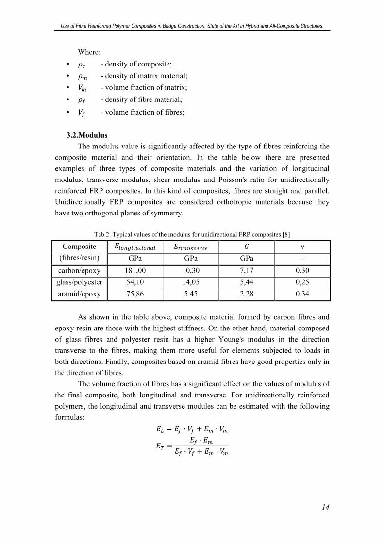
Tab.2. Typical values of the modulus for unidirectional FRP composites [8]
Composite
(fibres/resin)
�� �������� ���������� � ν
GPa GPa GPa -
carbon/epoxy 181,00 10,30 7,17 0,30
glass/polyester 54,10 14,05 5,44 0,25
aramid/epoxy 75,86 5,45 2,28 0,34
As shown in the table above, composite material formed by carbon fibres and
epoxy resin are those with the highest stiffness. On the other hand, material composed
of glass fibres and polyester resin has a higher Young's modulus in the direction
transverse to the fibres, making them more useful for elements subjected to loads in
both directions. Finally, composites based on aramid fibres have good properties only in
the direction of fibres.
The volume fraction of fibres has a significant effect on the values of modulus of
the final composite, both longitudinal and transverse. For unidirectionally reinforced
polymers, the longitudinal and transverse modules can be estimated with the following
formulas:
� � � · �� � � · ��
� �� · �
� · �� � � · ��
Use of Fibre Reinforced Polymer Composites in Bridge Construction. State of the Art in Hybrid and All-Composite Structures.
15
Where:
• � - longitudinal modulus of the composite (in the direction of fibres);
• � - modulus of the fibres;
• �� - volume fraction of fibres;
• � - modulus of the matrix;
• �� - volume fraction of matrix;
• � - transverse modulus of the composite (perpendicular to the direction of
fibres;
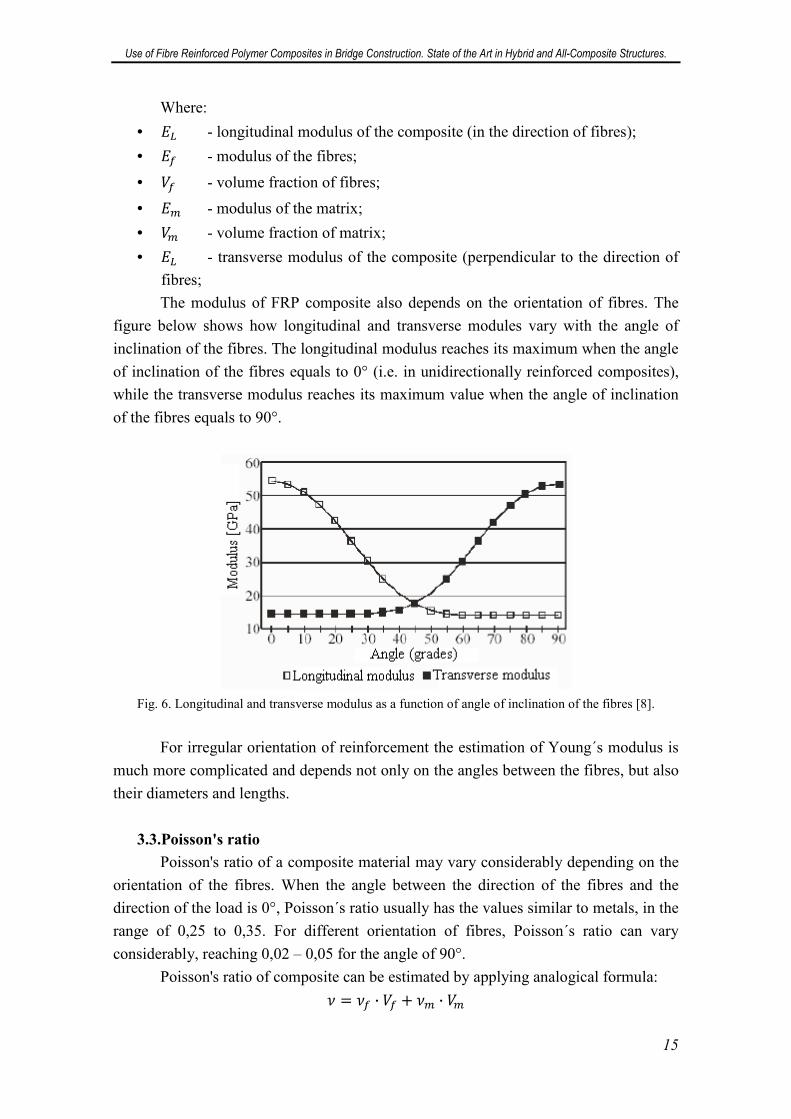
The modulus of FRP composite also depends on the orientation of fibres. The
figure below shows how longitudinal and transverse modules vary with the angle of
inclination of the fibres. The longitudinal modulus reaches its maximum when the angle
of inclination of the fibres equals to 0° (i.e. in unidirectionally reinforced composites),
while the transverse modulus reaches its maximum value when the angle of inclination
of the fibres equals to 90°.
Fig. 6. Longitudinal and transverse modulus as a function of angle of inclination of the fibres [8].
For irregular orientation of reinforcement the estimation of Young´s modulus is
much more complicated and depends not only on the angles between the fibres, but also
their diameters and lengths.
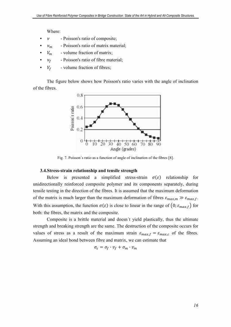
3.3.Poisson's ratio
Poisson's ratio of a composite material may vary considerably depending on the
orientation of the fibres. When the angle between the direction of the fibres and the
direction of the load is 0°, Poisson´s ratio usually has the values similar to metals, in the
range of 0,25 to 0,35. For different orientation of fibres, Poisson´s ratio can vary
considerably, reaching 0,02 – 0,05 for the angle of 90°.
Poisson's ratio of composite can be estimated by applying analogical formula:
� � �� · �� � �� · ��
Use of Fibre Reinforced Polymer Composites in Bridge Construction. State of the Art in Hybrid and All-Composite Structures.
16
Where:
• � - Poisson's ratio of composite;
• �� - Poisson's ratio of matrix material;
• �� - volume fraction of matrix;
• �� - Poisson's ratio of fibre material;
• �� - volume fraction of fibres;
The figure below shows how Poisson's ratio varies with the angle of inclination
of the fibres.
Fig. 7. Poisson´s ratio as a function of angle of inclination of the fibres [8].
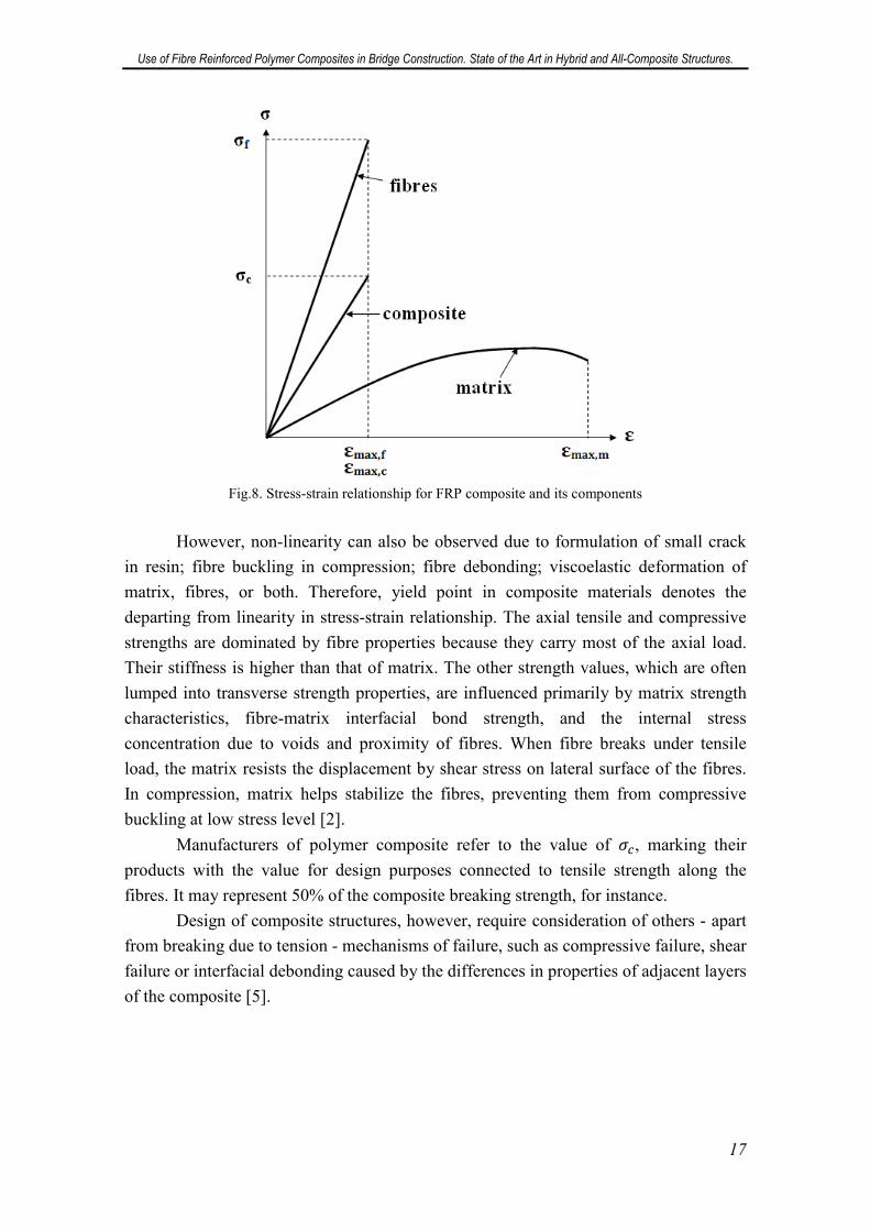
3.4.Stress-strain relationship and tensile strength
Below is presented a simplified stress-strain ���� relationship for
unidirectionally reinforced composite polymer and its components separately, during
tensile testing in the direction of the fibres. It is assumed that the maximum deformation
of the matrix is much larger than the maximum deformation of fibres ����,� ����,�.
With this assumption, the function ���� is close to linear in the range of !0; ����,�$ for
both: the fibres, the matrix and the composite.
Composite is a brittle material and doesn´t yield plastically, thus the ultimate
strength and breaking strength are the same. The destruction of the composite occurs for
values of stress as a result of the maximum strain ����,� � ����,� of the fibres.
Assuming an ideal bond between fibre and matrix, we can estimate that
�� � �� · %� � �� · %�
Use of Fibre Reinforced Polymer Composites in Bridge Construction. State of the Art in Hybrid and All-Composite Structures.
17
Fig.8. Stress-strain relationship for FRP composite and its components
However, non-linearity can also be observed due to formulation of small crack
in resin; fibre buckling in compression; fibre debonding; viscoelastic deformation of
matrix, fibres, or both. Therefore, yield point in composite materials denotes the
departing from linearity in stress-strain relationship. The axial tensile and compressive
strengths are dominated by fibre properties because they carry most of the axial load.
Their stiffness is higher than that of matrix. The other strength values, which are often
lumped into transverse strength properties, are influenced primarily by matrix strength
characteristics, fibre-matrix interfacial bond strength, and the internal stress
concentration due to voids and proximity of fibres. When fibre breaks under tensile
load, the matrix resists the displacement by shear stress on lateral surface of the fibres.
In compression, matrix helps stabilize the fibres, preventing them from compressive
buckling at low stress level [2].
Manufacturers of polymer composite refer to the value of ��, marking their
products with the value for design purposes connected to tensile strength along the
fibres. It may represent 50% of the composite breaking strength, for instance.
Design of composite structures, however, require consideration of others - apart
from breaking due to tension - mechanisms of failure, such as compressive failure, shear
failure or interfacial debonding caused by the differences in properties of adjacent layers
of the composite [5].
Use of Fibre Reinforced Polymer Composites in Bridge Construction. State of the Art in Hybrid and All-Composite Structures.
18
4. Areas of application
4.1.Repair and Retrofitting of Existing Bridge Structures
Strengthening and retrofitting of existing structures using externally bonded FRP
composites are one of the first applications of FRP introduced in civil engineering. The
technique is simple, rapid, and effective.
FRP used for strengthening and retrofitting can be in the forms of FRP sheet or
strip, depending on their application. Externally bonded FRP composites have been
used for increasing both flexural and shear capacity of concrete elements, including
girders, beams and slabs. Three methods are used for application of external FRP
reinforcement: adhesive bonding, hand lay-up or wet lay-up and resin infusion.
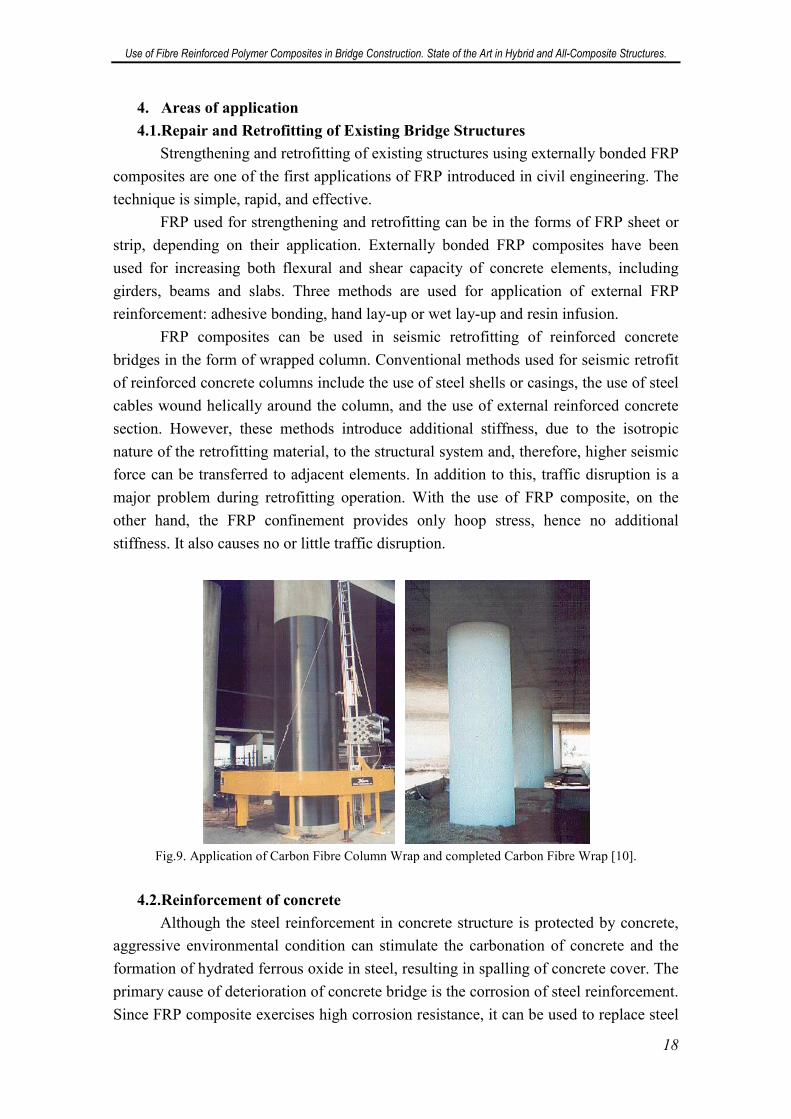
FRP composites can be used in seismic retrofitting of reinforced concrete
bridges in the form of wrapped column. Conventional methods used for seismic retrofit
of reinforced concrete columns include the use of steel shells or casings, the use of steel
cables wound helically around the column, and the use of external reinforced concrete
section. However, these methods introduce additional stiffness, due to the isotropic
nature of the retrofitting material, to the structural system and, therefore, higher seismic
force can be transferred to adjacent elements. In addition to this, traffic disruption is a
major problem during retrofitting operation. With the use of FRP composite, on the
other hand, the FRP confinement provides only hoop stress, hence no additional
stiffness. It also causes no or little traffic disruption.
Fig.9. Application of Carbon Fibre Column Wrap and completed Carbon Fibre Wrap [10].
4.2.Reinforcement of concrete
Although the steel reinforcement in concrete structure is protected by concrete,
aggressive environmental condition can stimulate the carbonation of concrete and the
formation of hydrated ferrous oxide in steel, resulting in spalling of concrete cover. The
primary cause of deterioration of concrete bridge is the corrosion of steel reinforcement.
Since FRP composite exercises high corrosion resistance, it can be used to replace steel
Use of Fibre Reinforced Polymer Composites in Bridge Construction. State of the Art in Hybrid and All-Composite Structures.
19
reinforcement in the forms of rebars for flexural and shear reinforcements, and tendons
for prestressing or post-tensioning. FRP rebar and tendon can take the form of one
dimensional or multidimensional shape, depending on type of application. There have
even been some attempts to incorporate wireless sensing into infrastructure using FRP
reinforcement. However, there are several challenges in using FRP rebar and tendon.
One issue is the linear elastic behaviour of FRP rebar when loaded to failure. This
means that concrete element reinforced using FRP rebar may not have the same ductile
failure of steel-reinforced element. Its lower modulus of elasticity also leads to
serviceability problems, such as larger deflection and larger crack widths [2].
4.3.Hybrid Bridge Structures
Hybrid bridges are understood as structures created by combining elements
made of traditional materials (usually girders) with elements made of FRP composites
(usually decks or cables/tendons). The piers are usually made of traditional materials.
Bridge design concepts are still mostly oriented towards the use of traditional materials
such as concrete or steel, which often prevents the full exploitation of the new materials
[3].
The most common example of a hybrid bridge is a construction composed of
steel or concrete girders to which FRP bridge deck is affixed. FRP bridge deck was
introduced as a solution providing easy installation, light weight and potential resistance
against environmental and chemical damages [2]. According to [3], a sole example of a
hybrid bridge with FRP girders and a wooden deck is the Tom´s Creek Bridge in the
USA constructed in 1997, but the list of similar constructions might be longer as
explained in chapter 12 of this paper.
However, all these are examples of merely substituting the material in traditional
designs. Apart from these, there exist material-adapted concepts, such as FRP
composite and concrete hybrid beam or hybrid tube system.
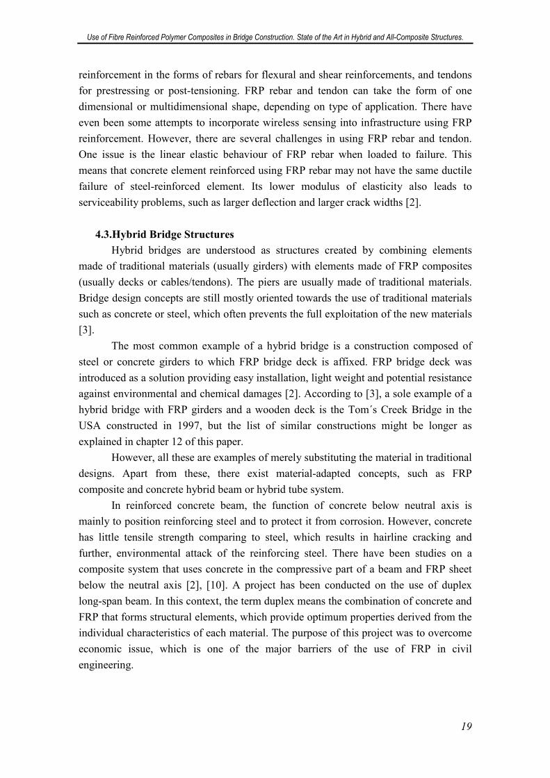
In reinforced concrete beam, the function of concrete below neutral axis is
mainly to position reinforcing steel and to protect it from corrosion. However, concrete
has little tensile strength comparing to steel, which results in hairline cracking and
further, environmental attack of the reinforcing steel. There have been studies on a
composite system that uses concrete in the compressive part of a beam and FRP sheet
below the neutral axis [2], [10]. A project has been conducted on the use of duplex
long-span beam. In this context, the term duplex means the combination of concrete and
FRP that forms structural elements, which provide optimum properties derived from the
individual characteristics of each material. The purpose of this project was to overcome
economic issue, which is one of the major barriers of the use of FRP in civil
engineering.
Use of Fibre Reinforced Polymer Composites in Bridge Construction. State of the Art in Hybrid and All-Composite Structures.
20
Fig.10. FRP composite and concrete hybrid beam [2].
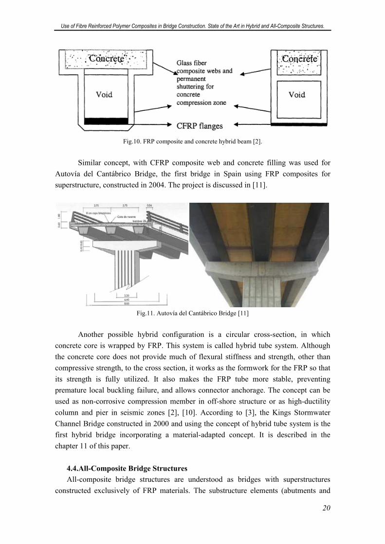
Similar concept, with CFRP composite web and concrete filling was used for
Autovía del Cantábrico Bridge, the first bridge in Spain using FRP composites for
superstructure, constructed in 2004. The project is discussed in [11].
Fig.11. Autovía del Cantábrico Bridge [11]
Another possible hybrid configuration is a circular cross-section, in which
concrete core is wrapped by FRP. This system is called hybrid tube system. Although
the concrete core does not provide much of flexural stiffness and strength, other than
compressive strength, to the cross section, it works as the formwork for the FRP so that
its strength is fully utilized. It also makes the FRP tube more stable, preventing
premature local buckling failure, and allows connector anchorage. The concept can be
used as non-corrosive compression member in off-shore structure or as high-ductility
column and pier in seismic zones [2], [10]. According to [3], the Kings Stormwater
Channel Bridge constructed in 2000 and using the concept of hybrid tube system is the
first hybrid bridge incorporating a material-adapted concept. It is described in the
chapter 11 of this paper.
4.4.All-Composite Bridge Structures
All-composite bridge structures are understood as bridges with superstructures
constructed exclusively of FRP materials. The substructure elements (abutments and
Use of Fibre Reinforced Polymer Composites in Bridge Construction. State of the Art in Hybrid and All-Composite Structures.
21
piers) usually consist of traditional materials. In these structures differences are evident
between traditional bridge concepts with simple material substitution and first steps
towards new material-adapted concepts. According to [3], the first bridge of this kind is
Miyun Bridge, constructed in China in 1982. It has a span of 20,7 m and consists of six
hand-laminated glass fibre/polyester sandwich girders.
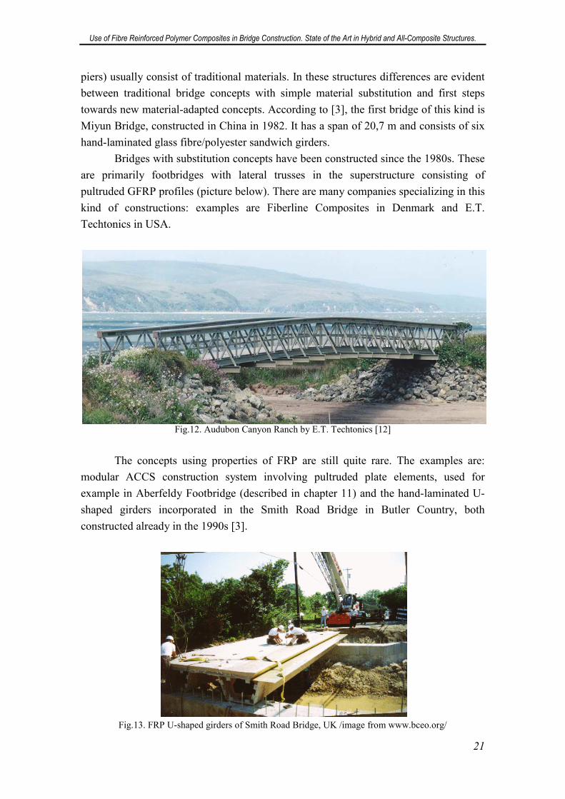
Bridges with substitution concepts have been constructed since the 1980s. These
are primarily footbridges with lateral trusses in the superstructure consisting of
pultruded GFRP profiles (picture below). There are many companies specializing in this
kind of constructions: examples are Fiberline Composites in Denmark and E.T.
Techtonics in USA.
Fig.12. Audubon Canyon Ranch by E.T. Techtonics [12]
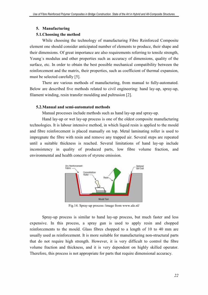
The concepts using properties of FRP are still quite rare. The examples are:
modular ACCS construction system involving pultruded plate elements, used for
example in Aberfeldy Footbridge (described in chapter 11) and the hand-laminated U-
shaped girders incorporated in the Smith Road Bridge in Butler Country, both
constructed already in the 1990s [3].
Fig.13. FRP U-shaped girders of Smith Road Bridge, UK /image from www.bceo.org/
Use of Fibre Reinforced Polymer Composites in Bridge Construction. State of the Art in Hybrid and All-Composite Structures.
22
5. Manufacturing
5.1.Choosing the method
While choosing the technology of manufacturing Fibre Reinforced Composite
element one should consider anticipated number of elements to produce, their shape and
their dimensions. Of great importance are also requirements referring to tensile strength,
Young´s modulus and other properties such as accuracy of dimensions, quality of the
surface, etc. In order to obtain the best possible mechanical compatibility between the
reinforcement and the matrix, their properties, such as coefficient of thermal expansion,
must be selected carefully [5].
There are various methods of manufacturing, from manual to fully-automated.
Below are described five methods related to civil engineering: hand lay-up, spray-up,
filament winding, resin transfer moulding and pultrusion [2].
5.2.Manual and semi-automated methods
Manual processes include methods such as hand lay-up and spray-up.
Hand lay-up or wet lay-up process is one of the oldest composite manufacturing
technologies. It is labour intensive method, in which liquid resin is applied to the mould
and fibre reinforcement is placed manually on top. Metal laminating roller is used to
impregnate the fibre with resin and remove any trapped air. Several steps are repeated
until a suitable thickness is reached. Several limitations of hand lay-up include
inconsistency in quality of produced parts, low fibre volume fraction, and
environmental and health concern of styrene emission.
Fig.14. Spray-up process /image from www.ale.nl/
Spray-up process is similar to hand lay-up process, but much faster and less
expensive. In this process, a spray gun is used to apply resin and chopped
reinforcements to the mould. Glass fibres chopped to a length of 10 to 40 mm are
usually used as reinforcement. It is more suitable for manufacturing non-structural parts
that do not require high strength. However, it is very difficult to control the fibre
volume fraction and thickness, and it is very dependent on highly skilled operator.
Therefore, this process is not appropriate for parts that require dimensional accuracy.
Use of Fibre Reinforced Polymer Composites in Bridge Construction. State of the Art in Hybrid and All-Composite Structures.
23
Fig.15. Spray-up process /image from www.ale.nl/
One of the semi-automated processes is resin infusion under flexible tooling
process. This method is mainly used to retrofit CFRP to steel, cast iron, and concrete
bridges. In this method, fibres are preformed in a mould and transported to site. The
preform is then attached to structure being retrofitted and enveloped by vacuum bagging
system, together with a resin supply. Resin is then injected into the preform, forming
both composite material and adhesive bond between the composite and the structure.
This process yields high fibre volume fraction as high as 55%.
5.3.Fully-automated methods
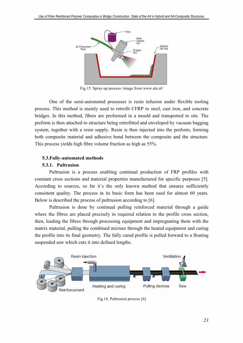
5.3.1. Pultrusion
Pultrusion is a process enabling continual production of FRP profiles with
constant cross sections and material properties manufactured for specific purposes [5].
According to sources, so far it´s the only known method that ensures sufficiently
consistent quality. The process in its basic form has been used for almost 60 years.
Below is described the process of pultrusion according to [6].
Pultrusion is done by continual pulling reinforced material through a guide
where the fibres are placed precisely in required relation to the profile cross section,
then, leading the fibres through processing equipment and impregnating them with the
matrix material, pulling the combined mixture through the heated equipment and curing
the profile into its final geometry. The fully cured profile is pulled forward to a floating
suspended saw which cuts it into defined lengths.
Fig.16. Pultrusion process [6]
Use of Fibre Reinforced Polymer Composites in Bridge Construction. State of the Art in Hybrid and All-Composite Structures.
24
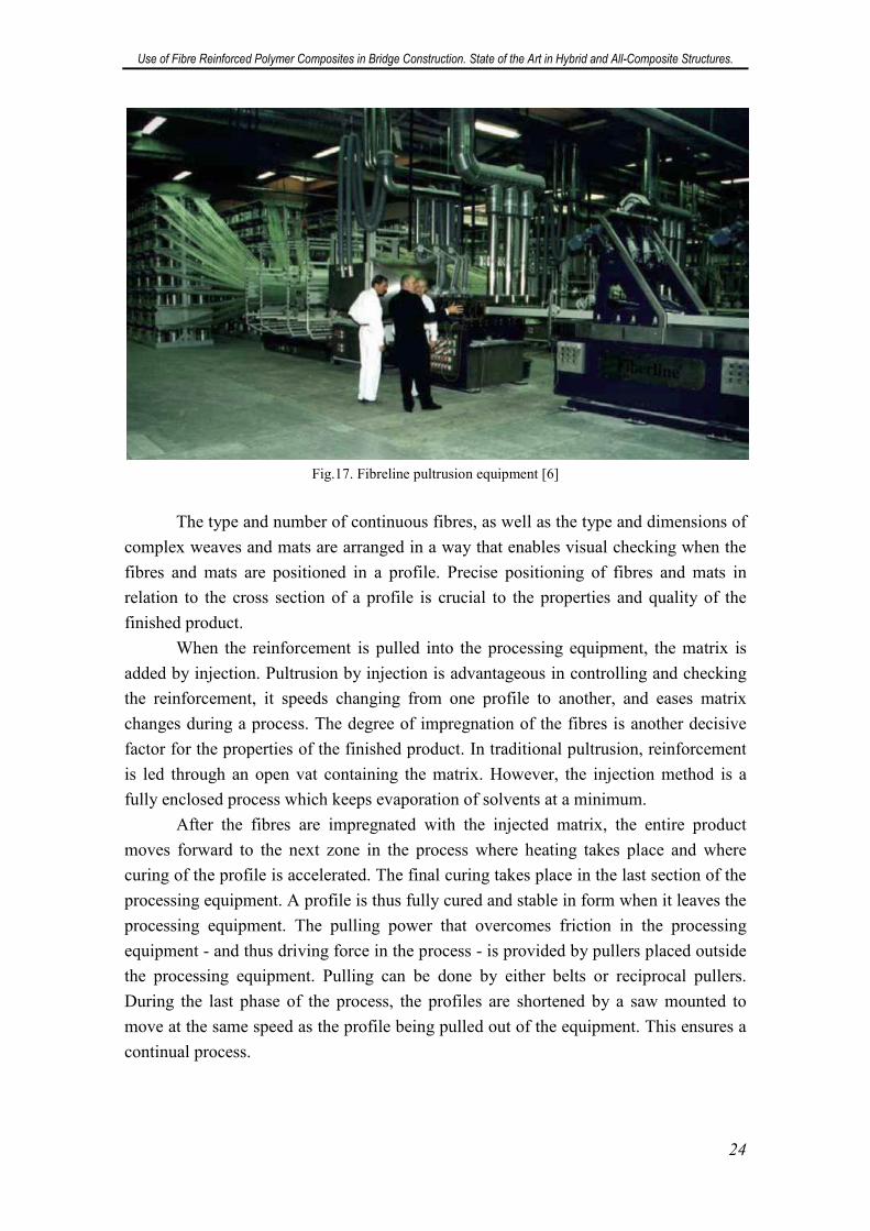
Fig.17. Fibreline pultrusion equipment [6]
The type and number of continuous fibres, as well as the type and dimensions of
complex weaves and mats are arranged in a way that enables visual checking when the
fibres and mats are positioned in a profile. Precise positioning of fibres and mats in
relation to the cross section of a profile is crucial to the properties and quality of the
finished product.
When the reinforcement is pulled into the processing equipment, the matrix is
added by injection. Pultrusion by injection is advantageous in controlling and checking
the reinforcement, it speeds changing from one profile to another, and eases matrix
changes during a process. The degree of impregnation of the fibres is another decisive
factor for the properties of the finished product. In traditional pultrusion, reinforcement
is led through an open vat containing the matrix. However, the injection method is a
fully enclosed process which keeps evaporation of solvents at a minimum.
After the fibres are impregnated with the injected matrix, the entire product
moves forward to the next zone in the process where heating takes place and where
curing of the profile is accelerated. The final curing takes place in the last section of the
processing equipment. A profile is thus fully cured and stable in form when it leaves the
processing equipment. The pulling power that overcomes friction in the processing
equipment - and thus driving force in the process - is provided by pullers placed outside
the processing equipment. Pulling can be done by either belts or reciprocal pullers.
During the last phase of the process, the profiles are shortened by a saw mounted to
move at the same speed as the profile being pulled out of the equipment. This ensures a
continual process.
Use of Fibre Reinforced Polymer Composites in Bridge Construction. State of the Art in Hybrid and All-Composite Structures.
25
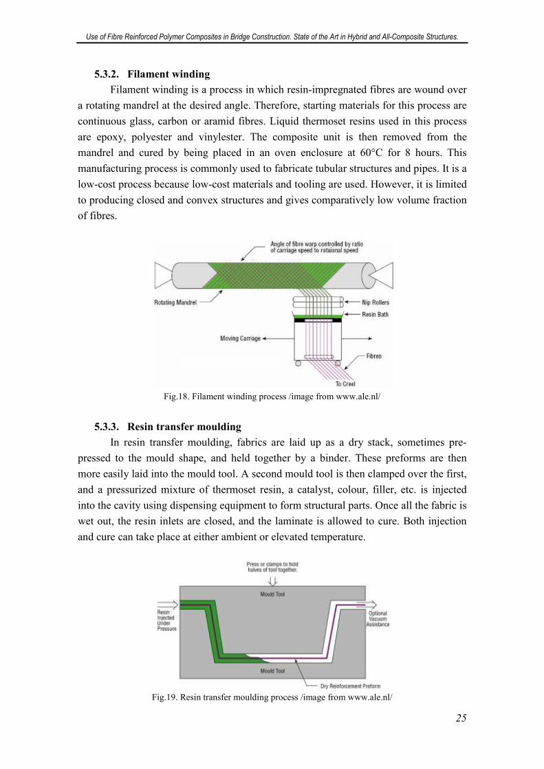
5.3.2. Filament winding
Filament winding is a process in which resin-impregnated fibres are wound over
a rotating mandrel at the desired angle. Therefore, starting materials for this process are
continuous glass, carbon or aramid fibres. Liquid thermoset resins used in this process
are epoxy, polyester and vinylester. The composite unit is then removed from the
mandrel and cured by being placed in an oven enclosure at 60°C for 8 hours. This
manufacturing process is commonly used to fabricate tubular structures and pipes. It is a
low-cost process because low-cost materials and tooling are used. However, it is limited
to producing closed and convex structures and gives comparatively low volume fraction
of fibres.
Fig.18. Filament winding process /image from www.ale.nl/
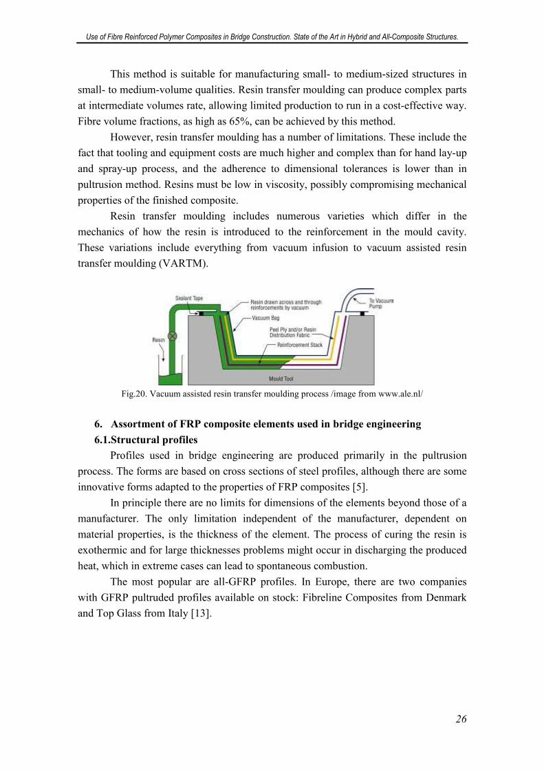
5.3.3. Resin transfer moulding
In resin transfer moulding, fabrics are laid up as a dry stack, sometimes pre-
pressed to the mould shape, and held together by a binder. These preforms are then
more easily laid into the mould tool. A second mould tool is then clamped over the first,
and a pressurized mixture of thermoset resin, a catalyst, colour, filler, etc. is injected
into the cavity using dispensing equipment to form structural parts. Once all the fabric is
wet out, the resin inlets are closed, and the laminate is allowed to cure. Both injection
and cure can take place at either ambient or elevated temperature.
Fig.19. Resin transfer moulding process /image from www.ale.nl/
Use of Fibre Reinforced Polymer Composites in Bridge Construction. State of the Art in Hybrid and All-Composite Structures.
26
This method is suitable for manufacturing small- to medium-sized structures in
small- to medium-volume qualities. Resin transfer moulding can produce complex parts
at intermediate volumes rate, allowing limited production to run in a cost-effective way.
Fibre volume fractions, as high as 65%, can be achieved by this method.
However, resin transfer moulding has a number of limitations. These include the
fact that tooling and equipment costs are much higher and complex than for hand lay-up
and spray-up process, and the adherence to dimensional tolerances is lower than in
pultrusion method. Resins must be low in viscosity, possibly compromising mechanical
properties of the finished composite.
Resin transfer moulding includes numerous varieties which differ in the
mechanics of how the resin is introduced to the reinforcement in the mould cavity.
These variations include everything from vacuum infusion to vacuum assisted resin
transfer moulding (VARTM).
Fig.20. Vacuum assisted resin transfer moulding process /image from www.ale.nl/
6. Assortment of FRP composite elements used in bridge engineering
6.1.Structural profiles
Profiles used in bridge engineering are produced primarily in the pultrusion
process. The forms are based on cross sections of steel profiles, although there are some
innovative forms adapted to the properties of FRP composites [5].
In principle there are no limits for dimensions of the elements beyond those of a
manufacturer. The only limitation independent of the manufacturer, dependent on
material properties, is the thickness of the element. The process of curing the resin is
exothermic and for large thicknesses problems might occur in discharging the produced
heat, which in extreme cases can lead to spontaneous combustion.
The most popular are all-GFRP profiles. In Europe, there are two companies
with GFRP pultruded profiles available on stock: Fibreline Composites from Denmark
and Top Glass from Italy [13].
Use of Fibre Reinforced Polymer Composites in Bridge Construction. State of the Art in Hybrid and All-Composite Structures.
27
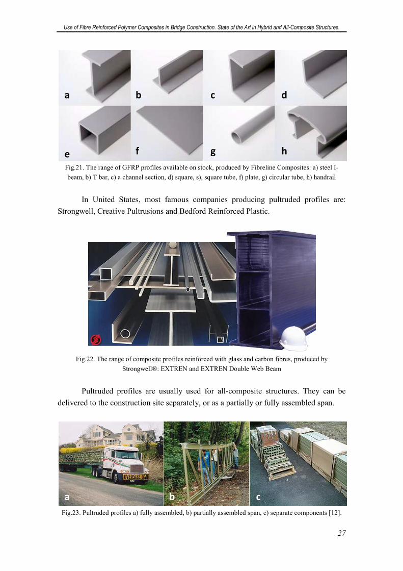
Fig.21. The range of GFRP profiles available on stock, produced by Fibreline Composites: a) steel I-
beam, b) T bar, c) a channel section, d) square, s), square tube, f) plate, g) circular tube, h) handrail
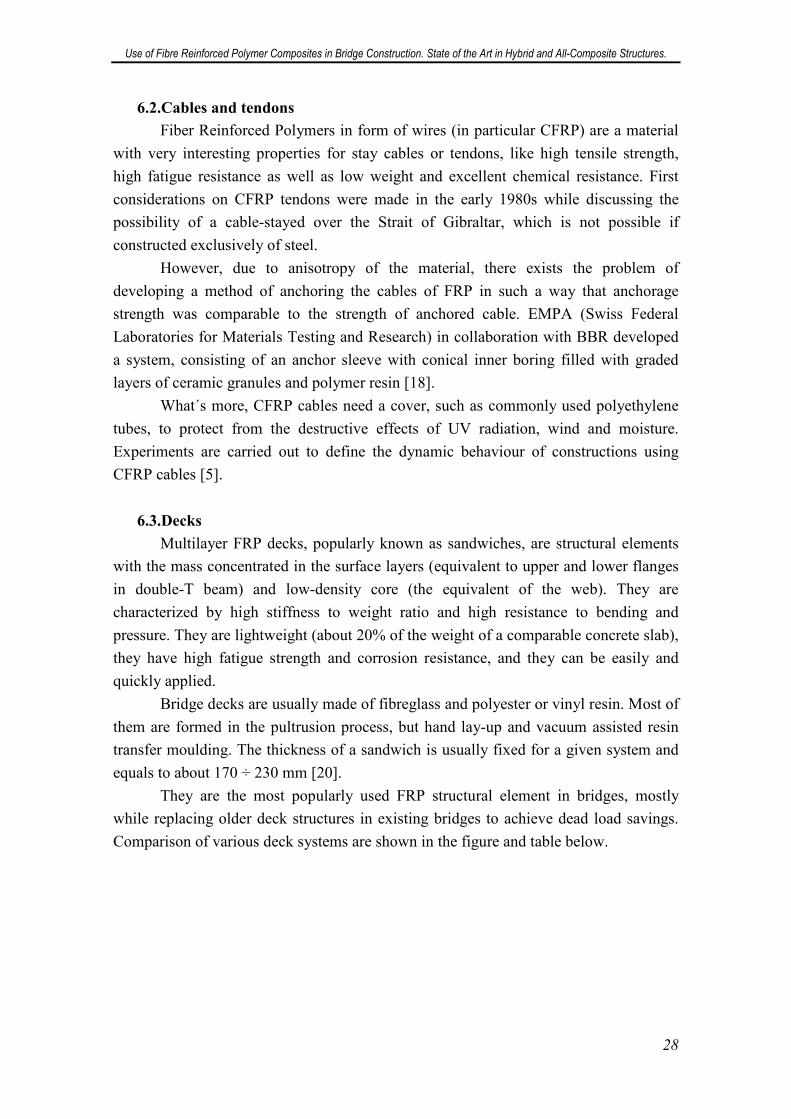
In United States, most famous companies producing pultruded profiles are:
Strongwell, Creative Pultrusions and Bedford Reinforced Plastic.
Fig.22. The range of composite profiles reinforced with glass and carbon fibres, produced by
Strongwell®: EXTREN and EXTREN Double Web Beam
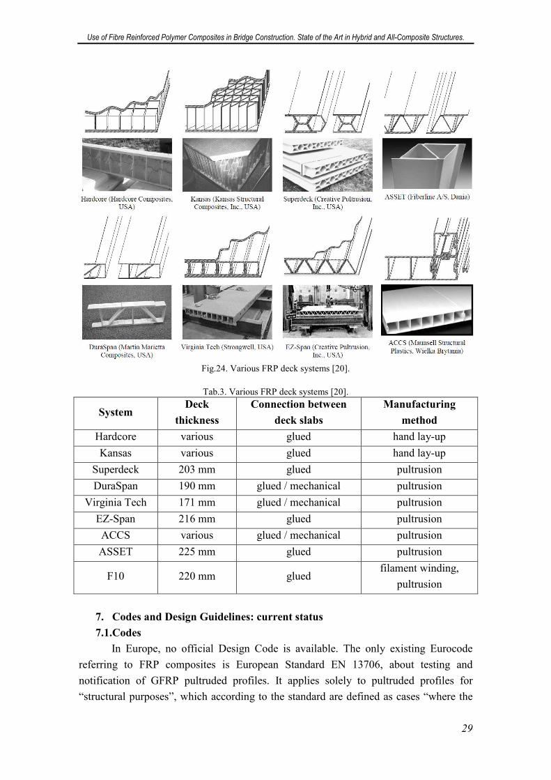
Pultruded profiles are usually used for all-composite structures. They can be
delivered to the construction site separately, or as a partially or fully assembled span.
Fig.23. Pultruded profiles a) fully assembled, b) partially assembled span, c) separate components [12].
a b c d
e f g h
a b c
Use of Fibre Reinforced Polymer Composites in Bridge Construction. State of the Art in Hybrid and All-Composite Structures.
28
6.2.Cables and tendons
Fiber Reinforced Polymers in form of wires (in particular CFRP) are a material
with very interesting properties for stay cables or tendons, like high tensile strength,
high fatigue resistance as well as low weight and excellent chemical resistance. First
considerations on CFRP tendons were made in the early 1980s while discussing the
possibility of a cable-stayed over the Strait of Gibraltar, which is not possible if
constructed exclusively of steel.
However, due to anisotropy of the material, there exists the problem of
developing a method of anchoring the cables of FRP in such a way that anchorage
strength was comparable to the strength of anchored cable. EMPA (Swiss Federal
Laboratories for Materials Testing and Research) in collaboration with BBR developed
a system, consisting of an anchor sleeve with conical inner boring filled with graded
layers of ceramic granules and polymer resin [18].
What´s more, CFRP cables need a cover, such as commonly used polyethylene
tubes, to protect from the destructive effects of UV radiation, wind and moisture.
Experiments are carried out to define the dynamic behaviour of constructions using
CFRP cables [5].
6.3.Decks
Multilayer FRP decks, popularly known as sandwiches, are structural elements
with the mass concentrated in the surface layers (equivalent to upper and lower flanges
in double-T beam) and low-density core (the equivalent of the web). They are
characterized by high stiffness to weight ratio and high resistance to bending and
pressure. They are lightweight (about 20% of the weight of a comparable concrete slab),
they have high fatigue strength and corrosion resistance, and they can be easily and
quickly applied.
Bridge decks are usually made of fibreglass and polyester or vinyl resin. Most of
them are formed in the pultrusion process, but hand lay-up and vacuum assisted resin
transfer moulding. The thickness of a sandwich is usually fixed for a given system and
equals to about 170 ÷ 230 mm [20].
They are the most popularly used FRP structural element in bridges, mostly
while replacing older deck structures in existing bridges to achieve dead load savings.
Comparison of various deck systems are shown in the figure and table below.
Use of Fibre Reinforced Polymer Composites in Bridge Construction. State of the Art in Hybrid and All-Composite Structures.
29
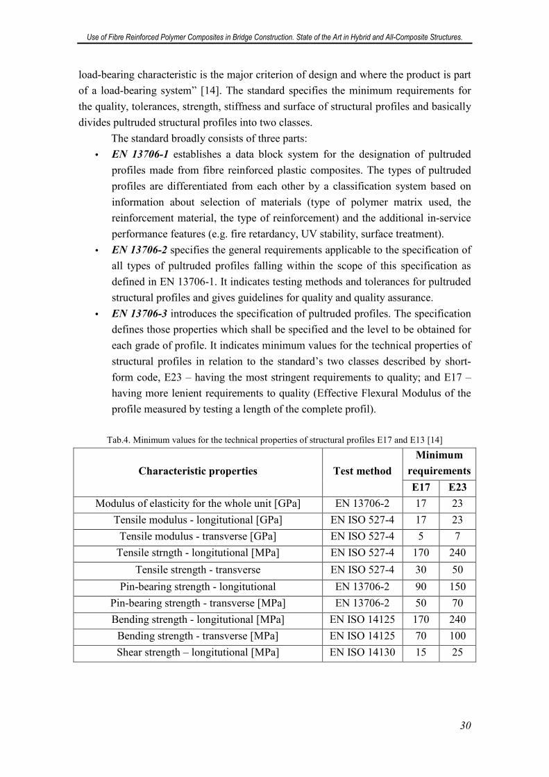
Fig.24. Various FRP deck systems [20].
Tab.3. Various FRP deck systems [20].
System Deck
thickness
Connection between
deck slabs
Manufacturing
method
Hardcore various glued hand lay-up
Kansas various glued hand lay-up
Superdeck 203 mm glued pultrusion
DuraSpan 190 mm glued / mechanical pultrusion
Virginia Tech 171 mm glued / mechanical pultrusion
EZ-Span 216 mm glued pultrusion
ACCS various glued / mechanical pultrusion
ASSET 225 mm glued pultrusion
F10 220 mm glued filament winding,
pultrusion
7. Codes and Design Guidelines: current status
7.1.Codes
In Europe, no official Design Code is available. The only existing Eurocode
referring to FRP composites is European Standard EN 13706, about testing and
notification of GFRP pultruded profiles. It applies solely to pultruded profiles for
“structural purposes”, which according to the standard are defined as cases “where the
Use of Fibre Reinforced Polymer Composites in Bridge Construction. State of the Art in Hybrid and All-Composite Structures.
30
load-bearing characteristic is the major criterion of design and where the product is part
of a load-bearing system” [14]. The standard specifies the minimum requirements for
the quality, tolerances, strength, stiffness and surface of structural profiles and basically
divides pultruded structural profiles into two classes.
The standard broadly consists of three parts:
• EN 13706-1 establishes a data block system for the designation of pultruded
profiles made from fibre reinforced plastic composites. The types of pultruded
profiles are differentiated from each other by a classification system based on
information about selection of materials (type of polymer matrix used, the
reinforcement material, the type of reinforcement) and the additional in-service
performance features (e.g. fire retardancy, UV stability, surface treatment).
• EN 13706-2 specifies the general requirements applicable to the specification of
all types of pultruded profiles falling within the scope of this specification as
defined in EN 13706-1. It indicates testing methods and tolerances for pultruded
structural profiles and gives guidelines for quality and quality assurance.
• EN 13706-3 introduces the specification of pultruded profiles. The specification
defines those properties which shall be specified and the level to be obtained for
each grade of profile. It indicates minimum values for the technical properties of
structural profiles in relation to the standard’s two classes described by short-
form code, E23 – having the most stringent requirements to quality; and E17 –
having more lenient requirements to quality (Effective Flexural Modulus of the
profile measured by testing a length of the complete profil).
Tab.4. Minimum values for the technical properties of structural profiles E17 and E13 [14]
Characteristic properties Test method
Minimum
requirements
E17 E23
Modulus of elasticity for the whole unit [GPa] EN 13706-2 17 23
Tensile modulus - longitutional [GPa] EN ISO 527-4 17 23
Tensile modulus - transverse [GPa] EN ISO 527-4 5 7
Tensile strngth - longitutional [MPa] EN ISO 527-4 170 240
Tensile strength - transverse EN ISO 527-4 30 50
Pin-bearing strength - longitutional EN 13706-2 90 150
Pin-bearing strength - transverse [MPa] EN 13706-2 50 70
Bending strength - longitutional [MPa] EN ISO 14125 170 240
Bending strength - transverse [MPa] EN ISO 14125 70 100
Shear strength – longitutional [MPa] EN ISO 14130 15 25
Use of Fibre Reinforced Polymer Composites in Bridge Construction. State of the Art in Hybrid and All-Composite Structures.
31
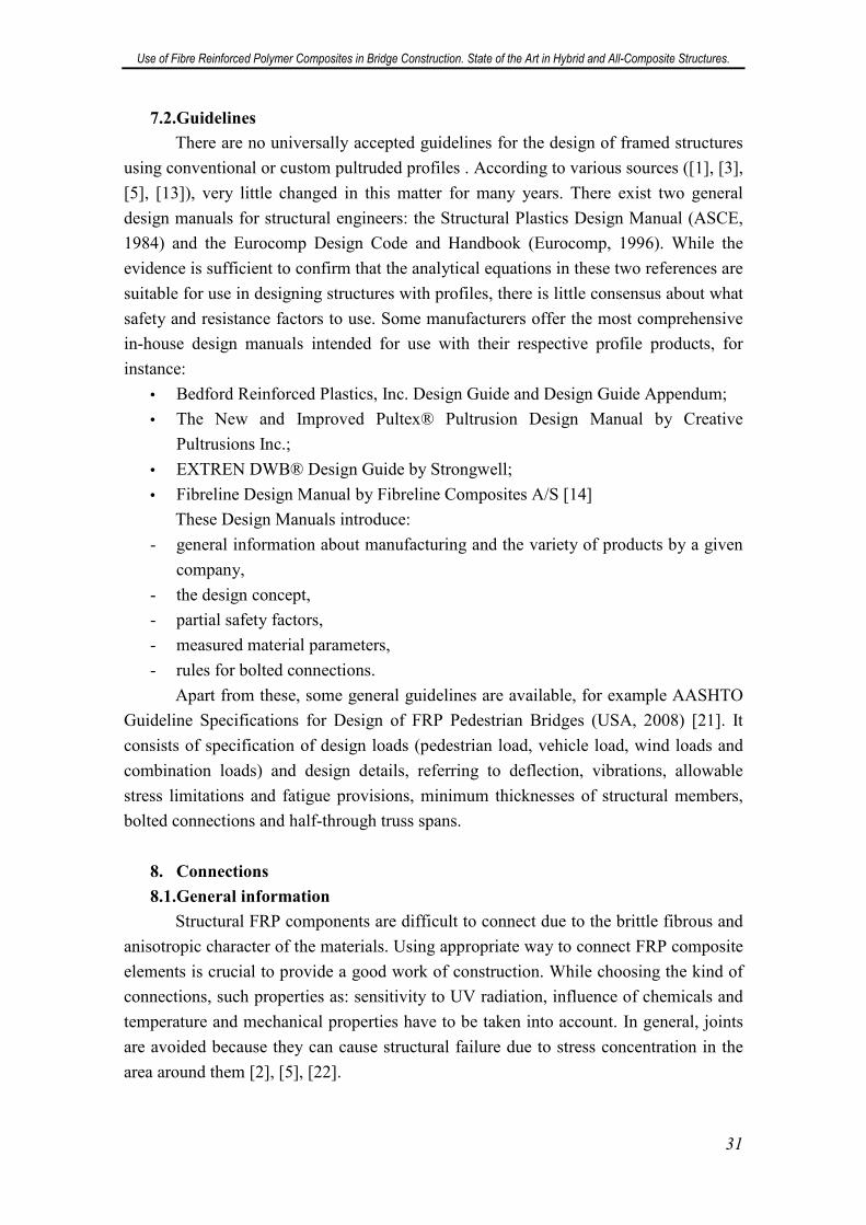
7.2.Guidelines
There are no universally accepted guidelines for the design of framed structures
using conventional or custom pultruded profiles . According to various sources ([1], [3],
[5], [13]), very little changed in this matter for many years. There exist two general
design manuals for structural engineers: the Structural Plastics Design Manual (ASCE,
1984) and the Eurocomp Design Code and Handbook (Eurocomp, 1996). While the
evidence is sufficient to confirm that the analytical equations in these two references are
suitable for use in designing structures with profiles, there is little consensus about what
safety and resistance factors to use. Some manufacturers offer the most comprehensive
in-house design manuals intended for use with their respective profile products, for
instance:
• Bedford Reinforced Plastics, Inc. Design Guide and Design Guide Appendum;
• The New and Improved Pultex® Pultrusion Design Manual by Creative
Pultrusions Inc.;
• EXTREN DWB® Design Guide by Strongwell;
• Fibreline Design Manual by Fibreline Composites A/S [14]
These Design Manuals introduce:
- general information about manufacturing and the variety of products by a given
company,
- the design concept,
- partial safety factors,
- measured material parameters,
- rules for bolted connections.
Apart from these, some general guidelines are available, for example AASHTO
Guideline Specifications for Design of FRP Pedestrian Bridges (USA, 2008) [21]. It
consists of specification of design loads (pedestrian load, vehicle load, wind loads and
combination loads) and design details, referring to deflection, vibrations, allowable
stress limitations and fatigue provisions, minimum thicknesses of structural members,
bolted connections and half-through truss spans.
8. Connections
8.1.General information
Structural FRP components are difficult to connect due to the brittle fibrous and
anisotropic character of the materials. Using appropriate way to connect FRP composite
elements is crucial to provide a good work of construction. While choosing the kind of
connections, such properties as: sensitivity to UV radiation, influence of chemicals and
temperature and mechanical properties have to be taken into account. In general, joints
are avoided because they can cause structural failure due to stress concentration in the
area around them [2], [5], [22].
Use of Fibre Reinforced Polymer Composites in Bridge Construction. State of the Art in Hybrid and All-Composite Structures.
32
Two types of connections are commonly used in FRP composite structures:
bonded (glued/adhesive) connections and mechanical connections, as well as their
combination.
8.2.Bonded connections
In adhesive connection, two parts or substrates are joined by some kind of
adhesive. The most commonly used glues are epoxy, acrylic and polyester glues - they
are chosen depending on the kind of resin used for FRP composite matrix.
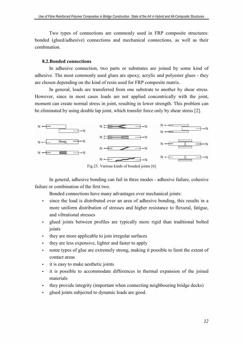
In general, loads are transferred from one substrate to another by shear stress.
However, since in most cases loads are not applied concentrically with the joint,
moment can create normal stress in joint, resulting in lower strength. This problem can
be eliminated by using double lap joint, which transfer force only by shear stress [2].
Fig.25. Various kinds of bonded joints [6]
In general, adhesive bonding can fail in three modes - adhesive failure, cohesive
failure or combination of the first two.
Bonded connections have many advantages over mechanical joints:
• since the load is distributed over an area of adhesive bonding, this results in a
more uniform distribution of stresses and higher resistance to flexural, fatigue,
and vibrational stresses
• glued joints between profiles are typically more rigid than traditional bolted
joints
• they are more applicable to join irregular surfaces
• they are less expensive, lighter and faster to apply
• some types of glue are extremely strong, making it possible to limit the extent of
contact areas
• it is easy to make aesthetic joints
• it is possible to accommodate differences in thermal expansion of the joined
materials
• they provide integrity (important when connecting neighbouring bridge decks)
• glued joints subjected to dynamic loads are good.
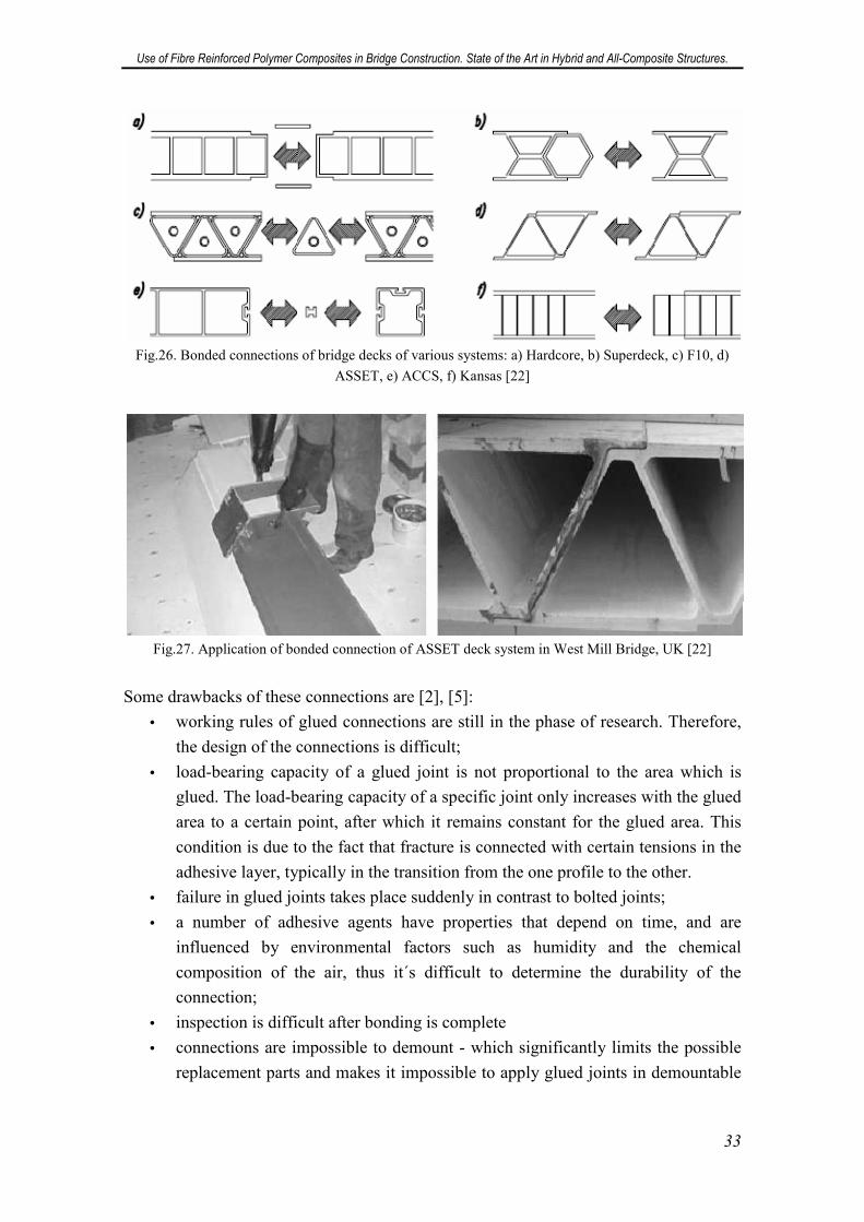
Use of Fibre Reinforced Polymer Composites in Bridge Construction. State of the Art in Hybrid and All-Composite Structures.
33
Fig.26. Bonded connections of bridge decks of various systems: a) Hardcore, b) Superdeck, c) F10, d)
ASSET, e) ACCS, f) Kansas [22]
Fig.27. Application of bonded connection of ASSET deck system in West Mill Bridge, UK [22]
Some drawbacks of these connections are [2], [5]:
• working rules of glued connections are still in the phase of research. Therefore,
the design of the connections is difficult;
• load-bearing capacity of a glued joint is not proportional to the area which is
glued. The load-bearing capacity of a specific joint only increases with the glued
area to a certain point, after which it remains constant for the glued area. This
condition is due to the fact that fracture is connected with certain tensions in the
adhesive layer, typically in the transition from the one profile to the other.
• failure in glued joints takes place suddenly in contrast to bolted joints;
• a number of adhesive agents have properties that depend on time, and are
influenced by environmental factors such as humidity and the chemical
composition of the air, thus it´s difficult to determine the durability of the
connection;
• inspection is difficult after bonding is complete
• connections are impossible to demount - which significantly limits the possible
replacement parts and makes it impossible to apply glued joints in demountable
Use of Fibre Reinforced Polymer Composites in Bridge Construction. State of the Art in Hybrid and All-Composite Structures.
34
bridges, where FRP composites could be successfully used due to their low
weight;
Because failure in glued joints occurs suddenly, joints in load-bearing structures
are normally secured with bolts. In many cases, an adhesive is applied to the contact
surfaces between the jointed profiles, thus increasing the rigidity of the joint in
operation. Around the world, intensive research is being carried out in the mode of
operation of glued joints. When sufficient knowledge becomes available, advance
verification of tests will be unnecessary, and glued joints will undoubtedly find favour
as primary joints in bearing structures.
8.3.Mechanical connections
Just as in the case of cross-sections, the technique of mechanical connections in
FRP composites is based on the solutions used for steel and its alloys [5], [22].
However, metals are characterized by continuity, homogeneity and isotropy, while FRP
composites are heterogeneous, anisotropic and brittle. Therefore, every incontinuity of
the fibres in FRP composite elements (i.e. holes for bolts in pultruded elements) reduces
the load bearing capacity of the element. The main advantage of mechanical
connections over bonded connections is that their working rules are defined and thus
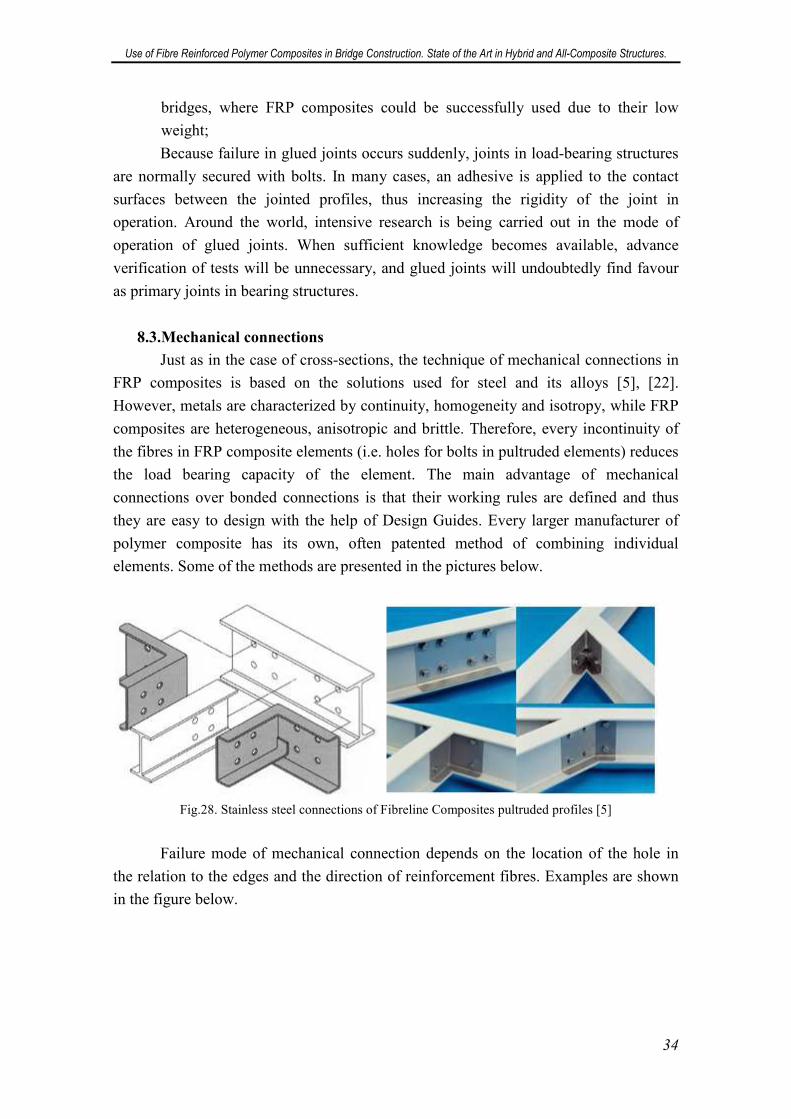
they are easy to design with the help of Design Guides. Every larger manufacturer of
polymer composite has its own, often patented method of combining individual
elements. Some of the methods are presented in the pictures below.
Fig.28. Stainless steel connections of Fibreline Composites pultruded profiles [5]
Failure mode of mechanical connection depends on the location of the hole in
the relation to the edges and the direction of reinforcement fibres. Examples are shown
in the figure below.
Use of Fibre Reinforced Polymer Composites in Bridge Construction. State of the Art in Hybrid and All-Composite Structures.
35
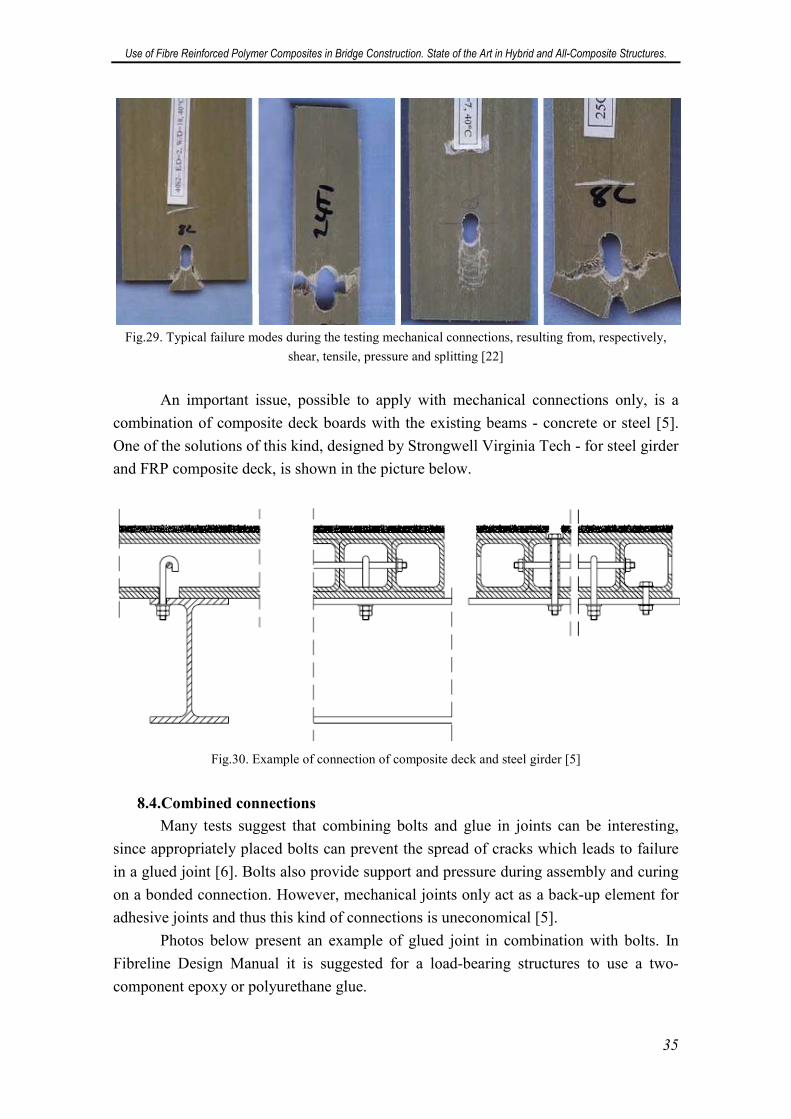
Fig.29. Typical failure modes during the testing mechanical connections, resulting from, respectively,
shear, tensile, pressure and splitting [22]
An important issue, possible to apply with mechanical connections only, is a
combination of composite deck boards with the existing beams - concrete or steel [5].
One of the solutions of this kind, designed by Strongwell Virginia Tech - for steel girder
and FRP composite deck, is shown in the picture below.
Fig.30. Example of connection of composite deck and steel girder [5]
8.4.Combined connections
Many tests suggest that combining bolts and glue in joints can be interesting,
since appropriately placed bolts can prevent the spread of cracks which leads to failure
in a glued joint [6]. Bolts also provide support and pressure during assembly and curing
on a bonded connection. However, mechanical joints only act as a back-up element for
adhesive joints and thus this kind of connections is uneconomical [5].
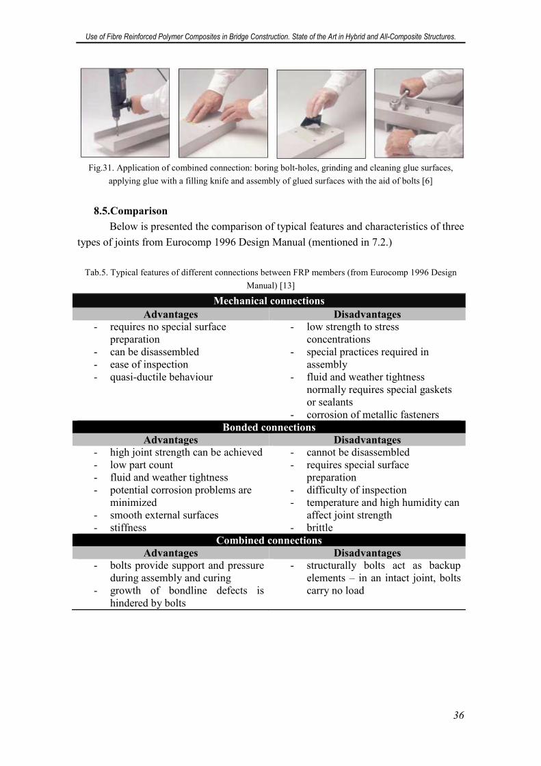
Photos below present an example of glued joint in combination with bolts. In
Fibreline Design Manual it is suggested for a load-bearing structures to use a two-
component epoxy or polyurethane glue.
Use of Fibre Reinforced Polymer Composites in Bridge Construction. State of the Art in Hybrid and All-Composite Structures.
36
Fig.31. Application of combined connection: boring bolt-holes, grinding and cleaning glue surfaces,
applying glue with a filling knife and assembly of glued surfaces with the aid of bolts [6]
8.5.Comparison
Below is presented the comparison of typical features and characteristics of three
types of joints from Eurocomp 1996 Design Manual (mentioned in 7.2.)
Tab.5. Typical features of different connections between FRP members (from Eurocomp 1996 Design
Manual) [13]
Mechanical connections
Advantages Disadvantages - requires no special surface
preparation - can be disassembled - ease of inspection - quasi-ductile behaviour
- low strength to stress concentrations
- special practices required in assembly
- fluid and weather tightness normally requires special gaskets or sealants
- corrosion of metallic fasteners Bonded connections
Advantages Disadvantages - high joint strength can be achieved - low part count - fluid and weather tightness - potential corrosion problems are
minimized - smooth external surfaces - stiffness
- cannot be disassembled - requires special surface
preparation - difficulty of inspection - temperature and high humidity can
affect joint strength - brittle
Combined connections
Advantages Disadvantages - bolts provide support and pressure
during assembly and curing - growth of bondline defects is
hindered by bolts
- structurally bolts act as backup elements – in an intact joint, bolts carry no load
Use of Fibre Reinforced Polymer Composites in Bridge Construction. State of the Art in Hybrid and All-Composite Structures.
37
Tab.6. Characteristics of different joint categories (from Eurocomp 1996 Design Manual) [13]
Mechanical Bonded Combined
Stress concentration at joint
Strength/weight ratio
Seal (water tightness)
Thermal insulation
Electrical insulation
Aesthetics (smooth joints)
Fatigue endurance
high
low
no
no
no
bad
bad
medium
medium
yes
yes
yes
good
good
medium
medium
yes
no
no
bad
good
Sensitive to peel loading
Disassembly
Inspection
Heat or pressure required
Tooling costs
Time to develop full strength
no
possible
easy
no
low
immediate
yes
impossible
difficult
yes/no
high
long
no
impossible
difficult
yes/no
low
long
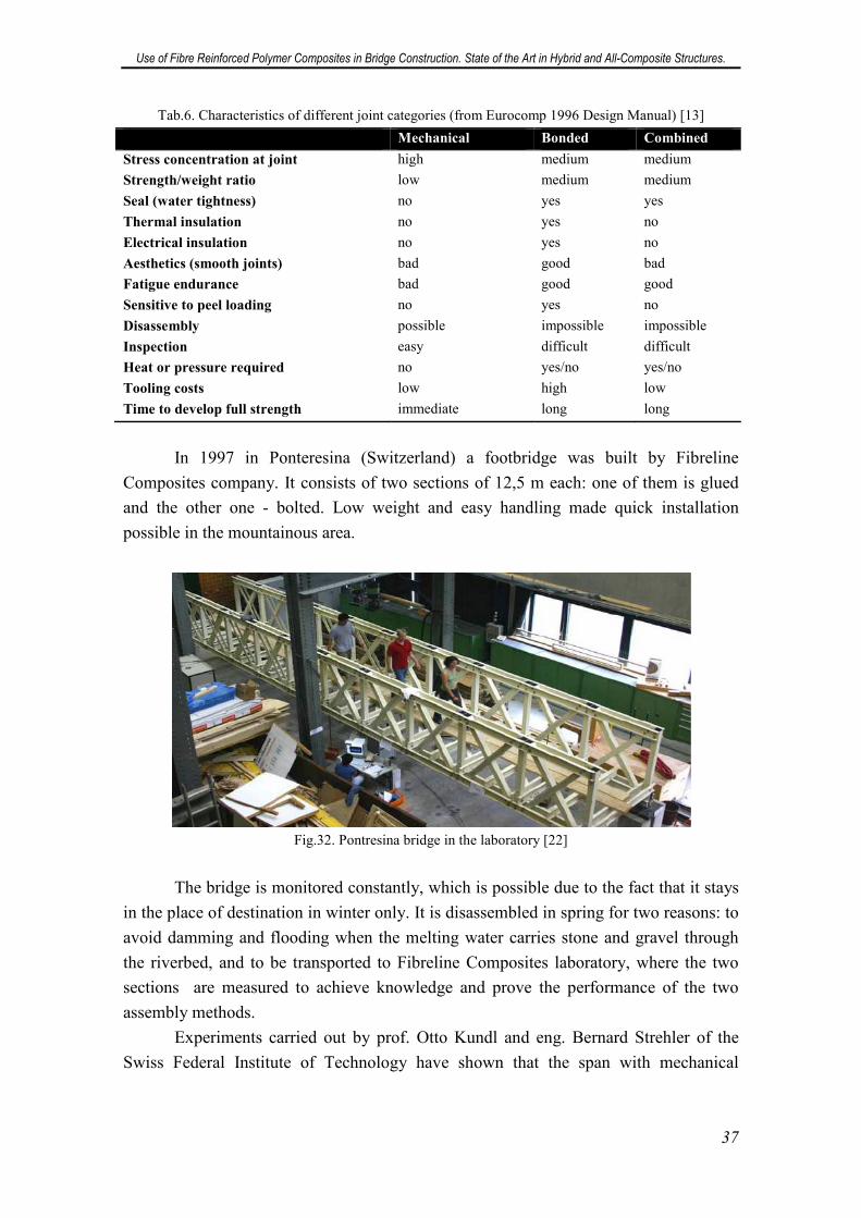
In 1997 in Ponteresina (Switzerland) a footbridge was built by Fibreline
Composites company. It consists of two sections of 12,5 m each: one of them is glued
and the other one - bolted. Low weight and easy handling made quick installation
possible in the mountainous area.
Fig.32. Pontresina bridge in the laboratory [22]
The bridge is monitored constantly, which is possible due to the fact that it stays
in the place of destination in winter only. It is disassembled in spring for two reasons: to
avoid damming and flooding when the melting water carries stone and gravel through
the riverbed, and to be transported to Fibreline Composites laboratory, where the two
sections are measured to achieve knowledge and prove the performance of the two
assembly methods.
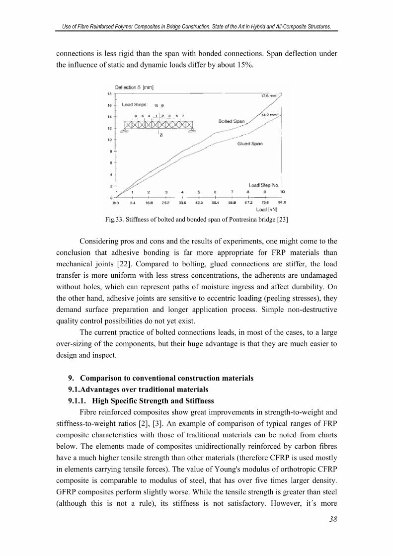
Experiments carried out by prof. Otto Kundl and eng. Bernard Strehler of the
Swiss Federal Institute of Technology have shown that the span with mechanical
Use of Fibre Reinforced Polymer Composites in Bridge Construction. State of the Art in Hybrid and All-Composite Structures.
38
connections is less rigid than the span with bonded connections. Span deflection under
the influence of static and dynamic loads differ by about 15%.
Fig.33. Stiffness of bolted and bonded span of Pontresina bridge [23]
Considering pros and cons and the results of experiments, one might come to the
conclusion that adhesive bonding is far more appropriate for FRP materials than
mechanical joints [22]. Compared to bolting, glued connections are stiffer, the load
transfer is more uniform with less stress concentrations, the adherents are undamaged
without holes, which can represent paths of moisture ingress and affect durability. On
the other hand, adhesive joints are sensitive to eccentric loading (peeling stresses), they
demand surface preparation and longer application process. Simple non-destructive
quality control possibilities do not yet exist.
The current practice of bolted connections leads, in most of the cases, to a large
over-sizing of the components, but their huge advantage is that they are much easier to
design and inspect.
9. Comparison to conventional construction materials
9.1.Advantages over traditional materials
9.1.1. High Specific Strength and Stiffness
Fibre reinforced composites show great improvements in strength-to-weight and
stiffness-to-weight ratios [2], [3]. An example of comparison of typical ranges of FRP
composite characteristics with those of traditional materials can be noted from charts
below. The elements made of composites unidirectionally reinforced by carbon fibres
have a much higher tensile strength than other materials (therefore CFRP is used mostly
in elements carrying tensile forces). The value of Young's modulus of orthotropic CFRP
composite is comparable to modulus of steel, that has over five times larger density.
GFRP composites perform slightly worse. While the tensile strength is greater than steel
(although this is not a rule), its stiffness is not satisfactory. However, it´s more
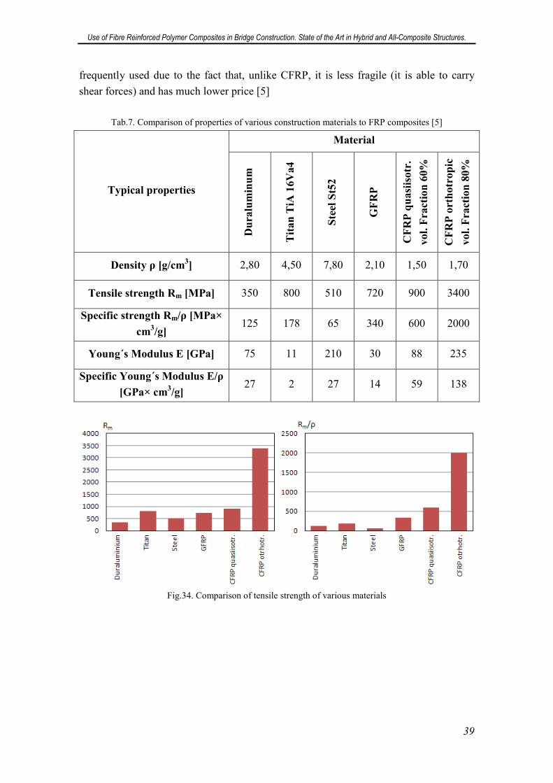
Use of Fibre Reinforced Polymer Composites in Bridge Construction. State of the Art in Hybrid and All-Composite Structures.
39
frequently used due to the fact that, unlike CFRP, it is less fragile (it is able to carry
shear forces) and has much lower price [5]
Tab.7. Comparison of properties of various construction materials to FRP composites [5]
Typical properties
Material
Du
ralu
min
um
Tit
an
TiA
16
Va
4
Ste
el S
t52
GF
RP
CF
RP
qu
asi
iso
tr.
vo
l. F
ract
ion
60
%
CF
RP
ort
ho
tro
pic
vo
l. F
ract
ion
80
%
Density ρ [g/cm3] 2,80 4,50 7,80 2,10 1,50 1,70
Tensile strength Rm [MPa] 350 800 510 720 900 3400
Specific strength Rm/ρ [MPa×
cm3/g]
125 178 65 340 600 2000
Young´s Modulus E [GPa] 75 11 210 30 88 235
Specific Young´s Modulus E/ρ
[GPa× cm3/g]
27 2 27 14 59 138
Fig.34. Comparison of tensile strength of various materials
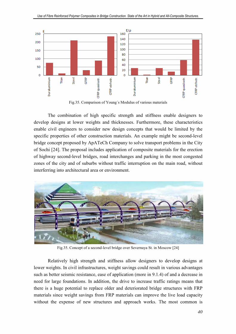
Use of Fibre Reinforced Polymer Composites in Bridge Construction. State of the Art in Hybrid and All-Composite Structures.
40
Fig.35. Comparison of Young´s Modulus of various materials
The combination of high specific strength and stiffness enable designers to
develop designs at lower weights and thicknesses. Furthermore, these characteristics
enable civil engineers to consider new design concepts that would be limited by the
specific properties of other construction materials. An example might be second-level
bridge concept proposed by ApATeCh Company to solve transport problems in the City
of Sochi [24]. The proposal includes application of composite materials for the erection
of highway second-level bridges, road interchanges and parking in the most congested
zones of the city and of suburbs without traffic interruption on the main road, without
interferring into architectural area or environment.
Fig.35. Concept of a second-level bridge over Severnaya St. in Moscow [24]
Relatively high strength and stiffness allow designers to develop designs at
lower weights. In civil infrastructures, weight savings could result in various advantages
such as better seismic resistance, ease of application (more in 9.1.4) of and a decrease in
need for large foundations. In addition, the drive to increase traffic ratings means that
there is a huge potential to replace older and deteriorated bridge structures with FRP
materials since weight savings from FRP materials can improve the live load capacity
without the expense of new structures and approach works. The most common is
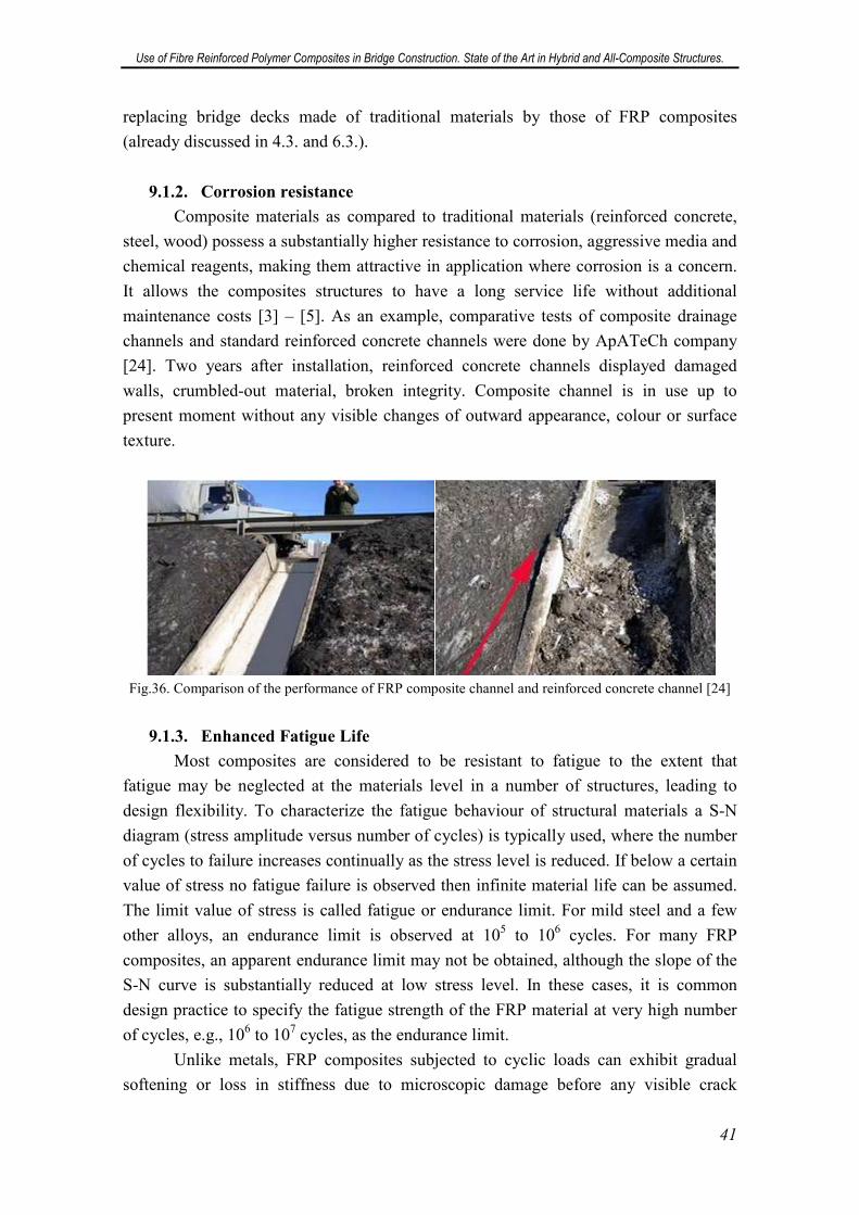
Use of Fibre Reinforced Polymer Composites in Bridge Construction. State of the Art in Hybrid and All-Composite Structures.
41
replacing bridge decks made of traditional materials by those of FRP composites
(already discussed in 4.3. and 6.3.).
9.1.2. Corrosion resistance
Composite materials as compared to traditional materials (reinforced concrete,
steel, wood) possess a substantially higher resistance to corrosion, aggressive media and
chemical reagents, making them attractive in application where corrosion is a concern.
It allows the composites structures to have a long service life without additional
maintenance costs [3] – [5]. As an example, comparative tests of composite drainage
channels and standard reinforced concrete channels were done by ApATeCh company
[24]. Two years after installation, reinforced concrete channels displayed damaged
walls, crumbled-out material, broken integrity. Composite channel is in use up to
present moment without any visible changes of outward appearance, colour or surface
texture.
Fig.36. Comparison of the performance of FRP composite channel and reinforced concrete channel [24]
9.1.3. Enhanced Fatigue Life
Most composites are considered to be resistant to fatigue to the extent that
fatigue may be neglected at the materials level in a number of structures, leading to
design flexibility. To characterize the fatigue behaviour of structural materials a S-N
diagram (stress amplitude versus number of cycles) is typically used, where the number
of cycles to failure increases continually as the stress level is reduced. If below a certain
value of stress no fatigue failure is observed then infinite material life can be assumed.
The limit value of stress is called fatigue or endurance limit. For mild steel and a few
other alloys, an endurance limit is observed at 105 to 106 cycles. For many FRP
composites, an apparent endurance limit may not be obtained, although the slope of the
S-N curve is substantially reduced at low stress level. In these cases, it is common
design practice to specify the fatigue strength of the FRP material at very high number
of cycles, e.g., 106 to 107 cycles, as the endurance limit.
Unlike metals, FRP composites subjected to cyclic loads can exhibit gradual
softening or loss in stiffness due to microscopic damage before any visible crack
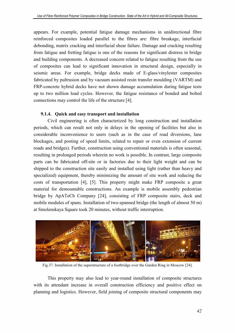
Use of Fibre Reinforced Polymer Composites in Bridge Construction. State of the Art in Hybrid and All-Composite Structures.
42
appears. For example, potential fatigue damage mechanisms in unidirectional fibre
reinforced composites loaded parallel to the fibres are: fibre breakage, interfacial
debonding, matrix cracking and interfacial shear failure. Damage and cracking resulting
from fatigue and fretting fatigue is one of the reasons for significant distress in bridge
and building components. A decreased concern related to fatigue resulting from the use
of composites can lead to significant innovation in structural design, especially in
seismic areas. For example, bridge decks made of E-glass/vinylester composites
fabricated by pultrusion and by vacuum assisted resin transfer moulding (VARTM) and
FRP-concrete hybrid decks have not shown damage accumulation during fatigue tests
up to two million load cycles. However, the fatigue resistance of bonded and bolted
connections may control the life of the structure [4].
9.1.4. Quick and easy transport and installation
Civil engineering is often characterized by long construction and installation
periods, which can result not only in delays in the opening of facilities but also in
considerable inconvenience to users (such as in the case of road diversions, lane
blockages, and posting of speed limits, related to repair or even extension of current
roads and bridges). Further, construction using conventional materials is often seasonal,
resulting in prolonged periods wherein no work is possible. In contrast, large composite
parts can be fabricated off-site or in factories due to their light weight and can be
shipped to the construction site easily and installed using light (rather than heavy and
specialized) equipment, thereby minimizing the amount of site work and reducing the
costs of transportation [4], [5]. This property might make FRP composite a great
material for demountable constructions. An example is mobile assembly pedestrian
bridge by ApATeCh Company [24], consisting of FRP composite stairs, deck and
mobile modules of spans. Installation of two-spanned bridge (the length of almost 50 m)
at Smolenskaya Square took 20 minutes, without traffic interruption.
Fig.37. Installation of the superstructure of a footbridge over the Garden Ring in Moscow [24].
This property may also lead to year-round installation of composite structures
with its attendant increase in overall construction efficiency and positive effect on
planning and logistics. However, field joining of composite structural components may
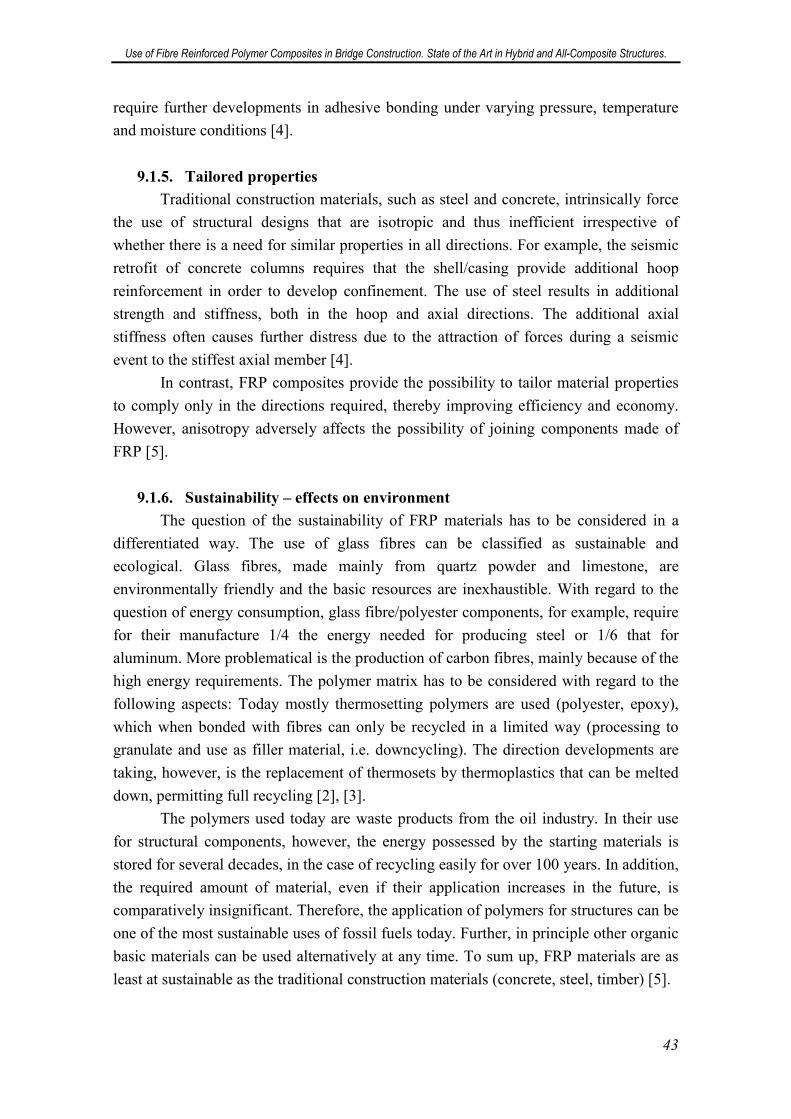
Use of Fibre Reinforced Polymer Composites in Bridge Construction. State of the Art in Hybrid and All-Composite Structures.
43
require further developments in adhesive bonding under varying pressure, temperature
and moisture conditions [4].
9.1.5. Tailored properties
Traditional construction materials, such as steel and concrete, intrinsically force
the use of structural designs that are isotropic and thus inefficient irrespective of
whether there is a need for similar properties in all directions. For example, the seismic
retrofit of concrete columns requires that the shell/casing provide additional hoop
reinforcement in order to develop confinement. The use of steel results in additional
strength and stiffness, both in the hoop and axial directions. The additional axial
stiffness often causes further distress due to the attraction of forces during a seismic
event to the stiffest axial member [4].
In contrast, FRP composites provide the possibility to tailor material properties
to comply only in the directions required, thereby improving efficiency and economy.
However, anisotropy adversely affects the possibility of joining components made of
FRP [5].
9.1.6. Sustainability – effects on environment
The question of the sustainability of FRP materials has to be considered in a
differentiated way. The use of glass fibres can be classified as sustainable and
ecological. Glass fibres, made mainly from quartz powder and limestone, are
environmentally friendly and the basic resources are inexhaustible. With regard to the
question of energy consumption, glass fibre/polyester components, for example, require
for their manufacture 1/4 the energy needed for producing steel or 1/6 that for
aluminum. More problematical is the production of carbon fibres, mainly because of the
high energy requirements. The polymer matrix has to be considered with regard to the
following aspects: Today mostly thermosetting polymers are used (polyester, epoxy),
which when bonded with fibres can only be recycled in a limited way (processing to
granulate and use as filler material, i.e. downcycling). The direction developments are
taking, however, is the replacement of thermosets by thermoplastics that can be melted
down, permitting full recycling [2], [3].
The polymers used today are waste products from the oil industry. In their use
for structural components, however, the energy possessed by the starting materials is
stored for several decades, in the case of recycling easily for over 100 years. In addition,
the required amount of material, even if their application increases in the future, is
comparatively insignificant. Therefore, the application of polymers for structures can be
one of the most sustainable uses of fossil fuels today. Further, in principle other organic
basic materials can be used alternatively at any time. To sum up, FRP materials are as
least at sustainable as the traditional construction materials (concrete, steel, timber) [5].
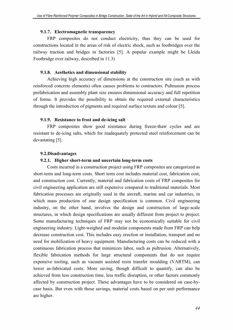
Use of Fibre Reinforced Polymer Composites in Bridge Construction. State of the Art in Hybrid and All-Composite Structures.
44
9.1.7. Electromagnetic transparency
FRP composites do not conduct electricity, thus they can be used for
constructions located in the areas of risk of electric shock, such as footbridges over the
railway traction and bridges in factories [5]. A popular example might be Lleida
Footbridge over railway, described in 11.3)
9.1.8. Aesthetics and dimensional stability
Achieving high accuracy of dimensions at the construction site (such as with
reinforced concrete elements) often causes problems to contractors. Pultrusion process
prefabrication and assembly plant size ensures dimensional accuracy and full repetition
of forms. It provides the possibility to obtain the required external characteristics
through the introduction of pigments and required surface texture and colour [5].
9.1.9. Resistance to frost and de-icing salt
FRP composites show good resistance during freeze-thaw cycles and are
resistant to de-icing salts, which for inadequately protected steel reinforcement can be
devastating [5].
9.2.Disadvantages
9.2.1. Higher short-term and uncertain long-term costs
Costs incurred in a construction project using FRP composites are categorized as
short-term and long-term costs. Short term cost includes material cost, fabrication cost,
and construction cost. Currently, material and fabrication costs of FRP composites for
civil engineering application are still expensive compared to traditional materials. Most
fabrication processes are originally used in the aircraft, marine and car industries, in
which mass production of one design specification is common. Civil engineering
industry, on the other hand, involves the design and construction of large-scale
structures, in which design specifications are usually different from project to project.
Some manufacturing techniques of FRP may not be economically suitable for civil
engineering industry. Light-weighed and modular components made from FRP can help
decrease construction cost. This includes easy erection or installation, transport and no
need for mobilization of heavy equipment. Manufacturing costs can be reduced with a
continuous fabrication process that minimizes labor, such as pultrusion. Alternatively,
flexible fabrication methods for large structural components that do not require
expensive tooling, such as vacuum assisted resin transfer moulding (VARTM), can
lower as-fabricated costs. More saving, though difficult to quantify, can also be
achieved from less construction time, less traffic disruption, or other factors commonly
affected by construction project. These advantages have to be considered on case-by-
case basis. But even with those savings, material costs based on per unit performance
are higher.
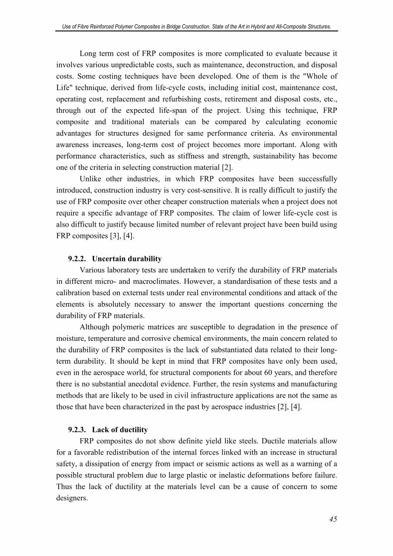
Use of Fibre Reinforced Polymer Composites in Bridge Construction. State of the Art in Hybrid and All-Composite Structures.
45
Long term cost of FRP composites is more complicated to evaluate because it
involves various unpredictable costs, such as maintenance, deconstruction, and disposal
costs. Some costing techniques have been developed. One of them is the "Whole of
Life" technique, derived from life-cycle costs, including initial cost, maintenance cost,
operating cost, replacement and refurbishing costs, retirement and disposal costs, etc.,
through out of the expected life-span of the project. Using this technique, FRP
composite and traditional materials can be compared by calculating economic
advantages for structures designed for same performance criteria. As environmental
awareness increases, long-term cost of project becomes more important. Along with
performance characteristics, such as stiffness and strength, sustainability has become
one of the criteria in selecting construction material [2].
Unlike other industries, in which FRP composites have been successfully
introduced, construction industry is very cost-sensitive. It is really difficult to justify the
use of FRP composite over other cheaper construction materials when a project does not
require a specific advantage of FRP composites. The claim of lower life-cycle cost is
also difficult to justify because limited number of relevant project have been build using
FRP composites [3], [4].
9.2.2. Uncertain durability
Various laboratory tests are undertaken to verify the durability of FRP materials
in different micro- and macroclimates. However, a standardisation of these tests and a
calibration based on external tests under real environmental conditions and attack of the
elements is absolutely necessary to answer the important questions concerning the
durability of FRP materials.
Although polymeric matrices are susceptible to degradation in the presence of
moisture, temperature and corrosive chemical environments, the main concern related to
the durability of FRP composites is the lack of substantiated data related to their long-
term durability. It should be kept in mind that FRP composites have only been used,
even in the aerospace world, for structural components for about 60 years, and therefore
there is no substantial anecdotal evidence. Further, the resin systems and manufacturing
methods that are likely to be used in civil infrastructure applications are not the same as
those that have been characterized in the past by aerospace industries [2], [4].
9.2.3. Lack of ductility
FRP composites do not show definite yield like steels. Ductile materials allow
for a favorable redistribution of the internal forces linked with an increase in structural
safety, a dissipation of energy from impact or seismic actions as well as a warning of a
possible structural problem due to large plastic or inelastic deformations before failure.
Thus the lack of ductility at the materials level can be a cause of concern to some
designers.
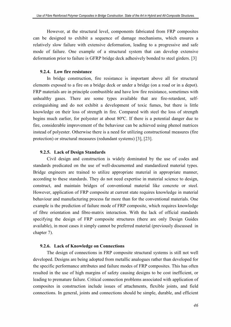
Use of Fibre Reinforced Polymer Composites in Bridge Construction. State of the Art in Hybrid and All-Composite Structures.
46
However, at the structural level, components fabricated from FRP composites
can be designed to exhibit a sequence of damage mechanisms, which ensures a
relatively slow failure with extensive deformation, leading to a progressive and safe
mode of failure. One example of a structural system that can develop extensive
deformation prior to failure is GFRP bridge deck adhesively bonded to steel girders. [3]
9.2.4. Low fire resistance
In bridge construction, fire resistance is important above all for structural
elements exposed to a fire on a bridge deck or under a bridge (on a road or in a depot).
FRP materials are in principle combustible and have low fire resistance, sometimes with
unhealthy gases. There are some types available that are fire-retardent, self-
extinguishing and do not exhibit a development of toxic fumes, but there is little
knowledge on their loss of strength in fire. Compared with steel the loss of strength
begins much earlier, for polyester at about 80ºC. If there is a potential danger due to
fire, considerable improvement of the behaviour can be achieved using phenol matrices
instead of polyester. Otherwise there is a need for utilizing constructional measures (fire
protection) or structural measures (redundant systems) [3], [23].
9.2.5. Lack of Design Standards
Civil design and construction is widely dominated by the use of codes and
standards predicated on the use of well-documented and standardized material types.
Bridge engineers are trained to utilize appropriate material in appropriate manner,
according to these standards. They do not need expertise in material science to design,
construct, and maintain bridges of conventional material like concrete or steel.
However, application of FRP composite at current state requires knowledge in material
behaviour and manufacturing process far more than for the conventional materials. One
example is the prediction of failure mode of FRP composite, which requires knowledge
of fibre orientation and fibre-matrix interaction. With the lack of official standards
specifying the design of FRP composite structures (there are only Design Guides
available), in most cases it simply cannot be preferred material (previously discussed in
chapter 7).
9.2.6. Lack of Knowledge on Connections
The design of connections in FRP composite structural systems is still not well
developed. Designs are being adopted from metallic analogues rather than developed for
the specific performance attributes and failure modes of FRP composites. This has often
resulted in the use of high margins of safety causing designs to be cost inefficient, or
leading to premature failure. Critical connection problems associated with application of
composites in construction include issues of attachments, flexible joints, and field
connections. In general, joints and connections should be simple, durable, and efficient
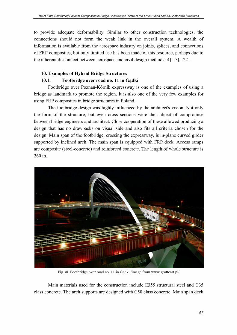
Use of Fibre Reinforced Polymer Composites in Bridge Construction. State of the Art in Hybrid and All-Composite Structures.
47
to provide adequate deformability. Similar to other construction technologies, the
connections should not form the weak link in the overall system. A wealth of
information is available from the aerospace industry on joints, splices, and connections
of FRP composites, but only limited use has been made of this resource, perhaps due to
the inherent disconnect between aerospace and civil design methods [4], [5], [22].
10. Examples of Hybrid Bridge Structures
10.1. Footbridge over road no. 11 in Gądki
Footbridge over Poznań-Kórnik expressway is one of the examples of using a
bridge as landmark to promote the region. It is also one of the very few examples for
using FRP composites in bridge structures in Poland.
The footbridge design was highly influenced by the architect's vision. Not only
the form of the structure, but even cross sections were the subject of compromise
between bridge engineers and architect. Close cooperation of these allowed producing a
design that has no drawbacks on visual side and also fits all criteria chosen for the
design. Main span of the footbridge, crossing the expressway, is in-plane curved girder
supported by inclined arch. The main span is equipped with FRP deck. Access ramps
are composite (steel-concrete) and reinforced concrete. The length of whole structure is
260 m.
Fig.38. Footbridge over road no. 11 in Gądki /image from www.grotteart.pl/
Main materials used for the construction include E355 structural steel and C35
class concrete. The arch supports are designed with C50 class concrete. Main span deck
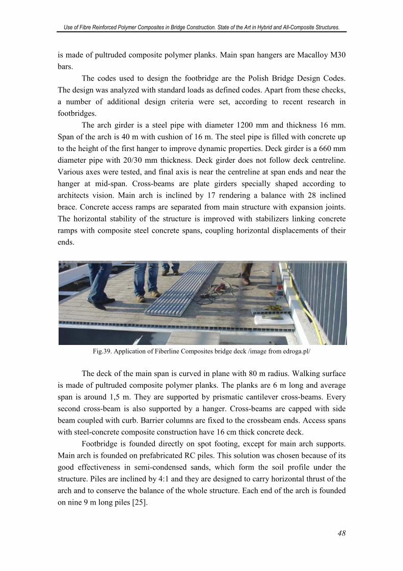
Use of Fibre Reinforced Polymer Composites in Bridge Construction. State of the Art in Hybrid and All-Composite Structures.
48
is made of pultruded composite polymer planks. Main span hangers are Macalloy M30
bars.
The codes used to design the footbridge are the Polish Bridge Design Codes.
The design was analyzed with standard loads as defined codes. Apart from these checks,
a number of additional design criteria were set, according to recent research in
footbridges.
The arch girder is a steel pipe with diameter 1200 mm and thickness 16 mm.
Span of the arch is 40 m with cushion of 16 m. The steel pipe is filled with concrete up
to the height of the first hanger to improve dynamic properties. Deck girder is a 660 mm
diameter pipe with 20/30 mm thickness. Deck girder does not follow deck centreline.
Various axes were tested, and final axis is near the centreline at span ends and near the
hanger at mid-span. Cross-beams are plate girders specially shaped according to
architects vision. Main arch is inclined by 17 rendering a balance with 28 inclined
brace. Concrete access ramps are separated from main structure with expansion joints.
The horizontal stability of the structure is improved with stabilizers linking concrete
ramps with composite steel concrete spans, coupling horizontal displacements of their
ends.
Fig.39. Application of Fiberline Composites bridge deck /image from edroga.pl/
The deck of the main span is curved in plane with 80 m radius. Walking surface
is made of pultruded composite polymer planks. The planks are 6 m long and average
span is around 1,5 m. They are supported by prismatic cantilever cross-beams. Every
second cross-beam is also supported by a hanger. Cross-beams are capped with side
beam coupled with curb. Barrier columns are fixed to the crossbeam ends. Access spans
with steel-concrete composite construction have 16 cm thick concrete deck.
Footbridge is founded directly on spot footing, except for main arch supports.
Main arch is founded on prefabricated RC piles. This solution was chosen because of its
good effectiveness in semi-condensed sands, which form the soil profile under the
structure. Piles are inclined by 4:1 and they are designed to carry horizontal thrust of the
arch and to conserve the balance of the whole structure. Each end of the arch is founded
on nine 9 m long piles [25].
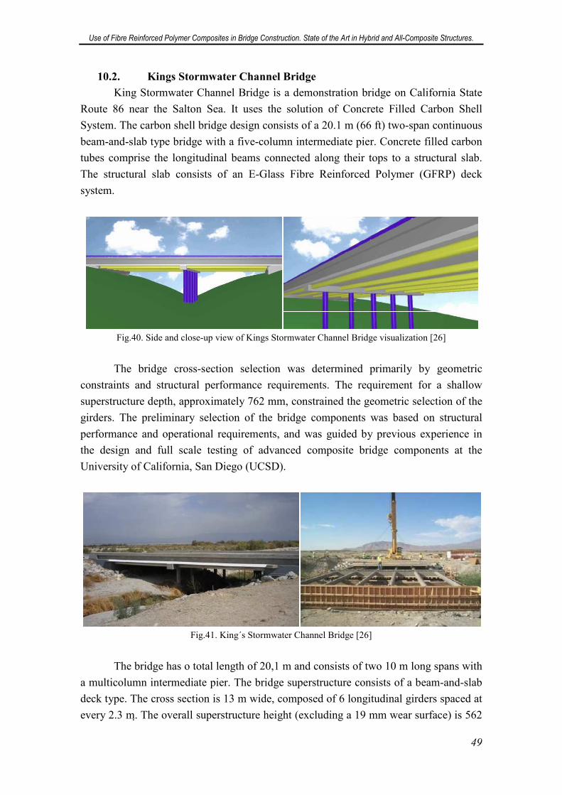
Use of Fibre Reinforced Polymer Composites in Bridge Construction. State of the Art in Hybrid and All-Composite Structures.
49
10.2. Kings Stormwater Channel Bridge
King Stormwater Channel Bridge is a demonstration bridge on California State
Route 86 near the Salton Sea. It uses the solution of Concrete Filled Carbon Shell
System. The carbon shell bridge design consists of a 20.1 m (66 ft) two-span continuous
beam-and-slab type bridge with a five-column intermediate pier. Concrete filled carbon
tubes comprise the longitudinal beams connected along their tops to a structural slab.
The structural slab consists of an E-Glass Fibre Reinforced Polymer (GFRP) deck
system.
Fig.40. Side and close-up view of Kings Stormwater Channel Bridge visualization [26]
The bridge cross-section selection was determined primarily by geometric
constraints and structural performance requirements. The requirement for a shallow
superstructure depth, approximately 762 mm, constrained the geometric selection of the
girders. The preliminary selection of the bridge components was based on structural
performance and operational requirements, and was guided by previous experience in
the design and full scale testing of advanced composite bridge components at the
University of California, San Diego (UCSD).
Fig.41. King´s Stormwater Channel Bridge [26]
The bridge has o total length of 20,1 m and consists of two 10 m long spans with
a multicolumn intermediate pier. The bridge superstructure consists of a beam-and-slab
deck type. The cross section is 13 m wide, composed of 6 longitudinal girders spaced at
every 2.3 m. The overall superstructure height (excluding a 19 mm wear surface) is 562
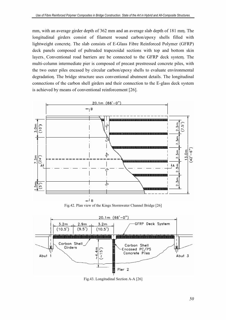
Use of Fibre Reinforced Polymer Composites in Bridge Construction. State of the Art in Hybrid and All-Composite Structures.
50
mm, with an average girder depth of 362 mm and an average slab depth of 181 mm. The
longitudinal girders consist of filament wound carbon/epoxy shells filled with
lightweight concrete. The slab consists of E-Glass Fibre Reinforced Polymer (GFRP)
deck panels composed of pultruded trapezoidal sections with top and bottom skin
layers. Conventional road barriers are be connected to the GFRP deck system. The
multi-column intermediate pier is composed of precast prestressed concrete piles, with
the two outer piles encased by circular carbon/epoxy shells to evaluate environmental
degradation. The bridge structure uses conventional abutment details. The longitudinal
connections of the carbon shell girders and their connection to the E-glass deck system
is achieved by means of conventional reinforcement [26].
Fig.42. Plan view of the Kings Stormwater Channel Bridge [26]
Fig.43. Longitudinal Section A-A [26]
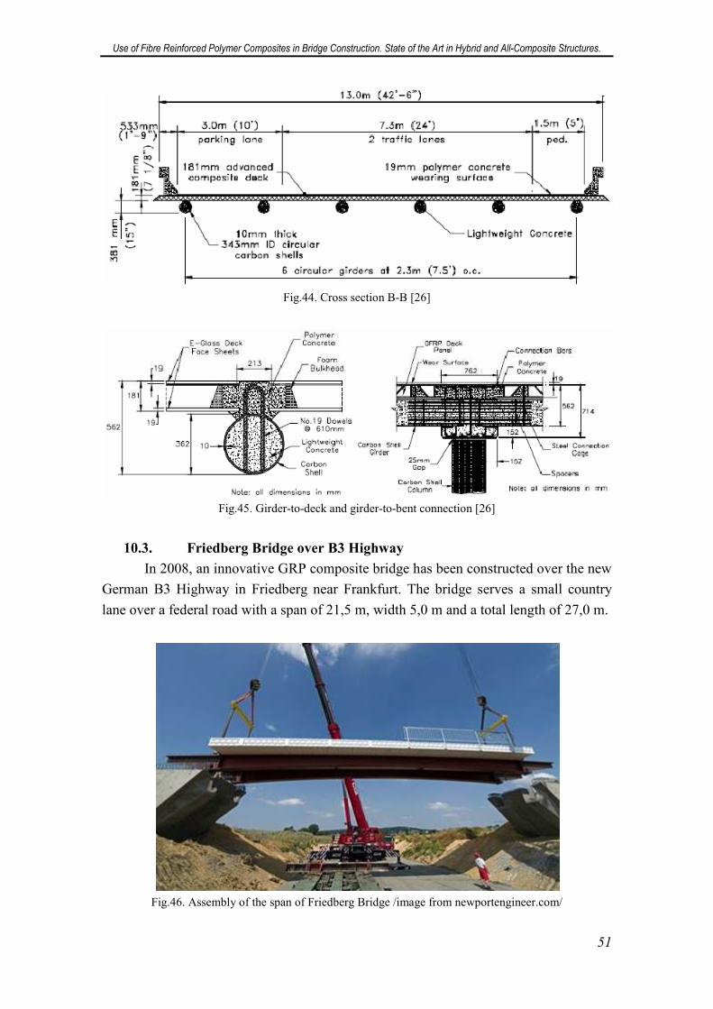
Use of Fibre Reinforced Polymer Composites in Bridge Construction. State of the Art in Hybrid and All-Composite Structures.
51
Fig.44. Cross section B-B [26]
Fig.45. Girder-to-deck and girder-to-bent connection [26]
10.3. Friedberg Bridge over B3 Highway
In 2008, an innovative GRP composite bridge has been constructed over the new
German B3 Highway in Friedberg near Frankfurt. The bridge serves a small country
lane over a federal road with a span of 21,5 m, width 5,0 m and a total length of 27,0 m.
Fig.46. Assembly of the span of Friedberg Bridge /image from newportengineer.com/
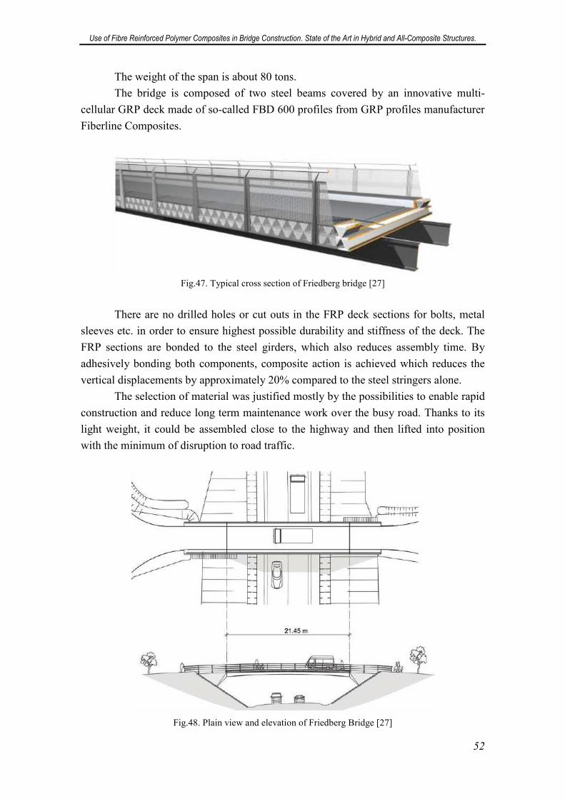
Use of Fibre Reinforced Polymer Composites in Bridge Construction. State of the Art in Hybrid and All-Composite Structures.
52
The weight of the span is about 80 tons.
The bridge is composed of two steel beams covered by an innovative multi-
cellular GRP deck made of so-called FBD 600 profiles from GRP profiles manufacturer
Fiberline Composites.
Fig.47. Typical cross section of Friedberg bridge [27]
There are no drilled holes or cut outs in the FRP deck sections for bolts, metal
sleeves etc. in order to ensure highest possible durability and stiffness of the deck. The
FRP sections are bonded to the steel girders, which also reduces assembly time. By
adhesively bonding both components, composite action is achieved which reduces the
vertical displacements by approximately 20% compared to the steel stringers alone.
The selection of material was justified mostly by the possibilities to enable rapid
construction and reduce long term maintenance work over the busy road. Thanks to its
light weight, it could be assembled close to the highway and then lifted into position
with the minimum of disruption to road traffic.
Fig.48. Plain view and elevation of Friedberg Bridge [27]
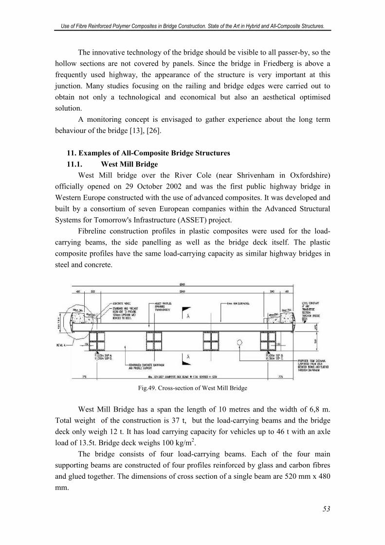
Use of Fibre Reinforced Polymer Composites in Bridge Construction. State of the Art in Hybrid and All-Composite Structures.
53
The innovative technology of the bridge should be visible to all passer-by, so the
hollow sections are not covered by panels. Since the bridge in Friedberg is above a
frequently used highway, the appearance of the structure is very important at this
junction. Many studies focusing on the railing and bridge edges were carried out to
obtain not only a technological and economical but also an aesthetical optimised
solution.
A monitoring concept is envisaged to gather experience about the long term
behaviour of the bridge [13], [26].
11. Examples of All-Composite Bridge Structures
11.1. West Mill Bridge
West Mill bridge over the River Cole (near Shrivenham in Oxfordshire)
officially opened on 29 October 2002 and was the first public highway bridge in
Western Europe constructed with the use of advanced composites. It was developed and
built by a consortium of seven European companies within the Advanced Structural
Systems for Tomorrow's Infrastructure (ASSET) project.
Fibreline construction profiles in plastic composites were used for the load-
carrying beams, the side panelling as well as the bridge deck itself. The plastic
composite profiles have the same load-carrying capacity as similar highway bridges in
steel and concrete.
Fig.49. Cross-section of West Mill Bridge
West Mill Bridge has a span the length of 10 metres and the width of 6,8 m.
Total weight of the construction is 37 t, but the load-carrying beams and the bridge
deck only weigh 12 t. It has load carrying capacity for vehicles up to 46 t with an axle
load of 13.5t. Bridge deck weighs 100 kg/m2.
The bridge consists of four load-carrying beams. Each of the four main
supporting beams are constructed of four profiles reinforced by glass and carbon fibres
and glued together. The dimensions of cross section of a single beam are 520 mm x 480
mm.
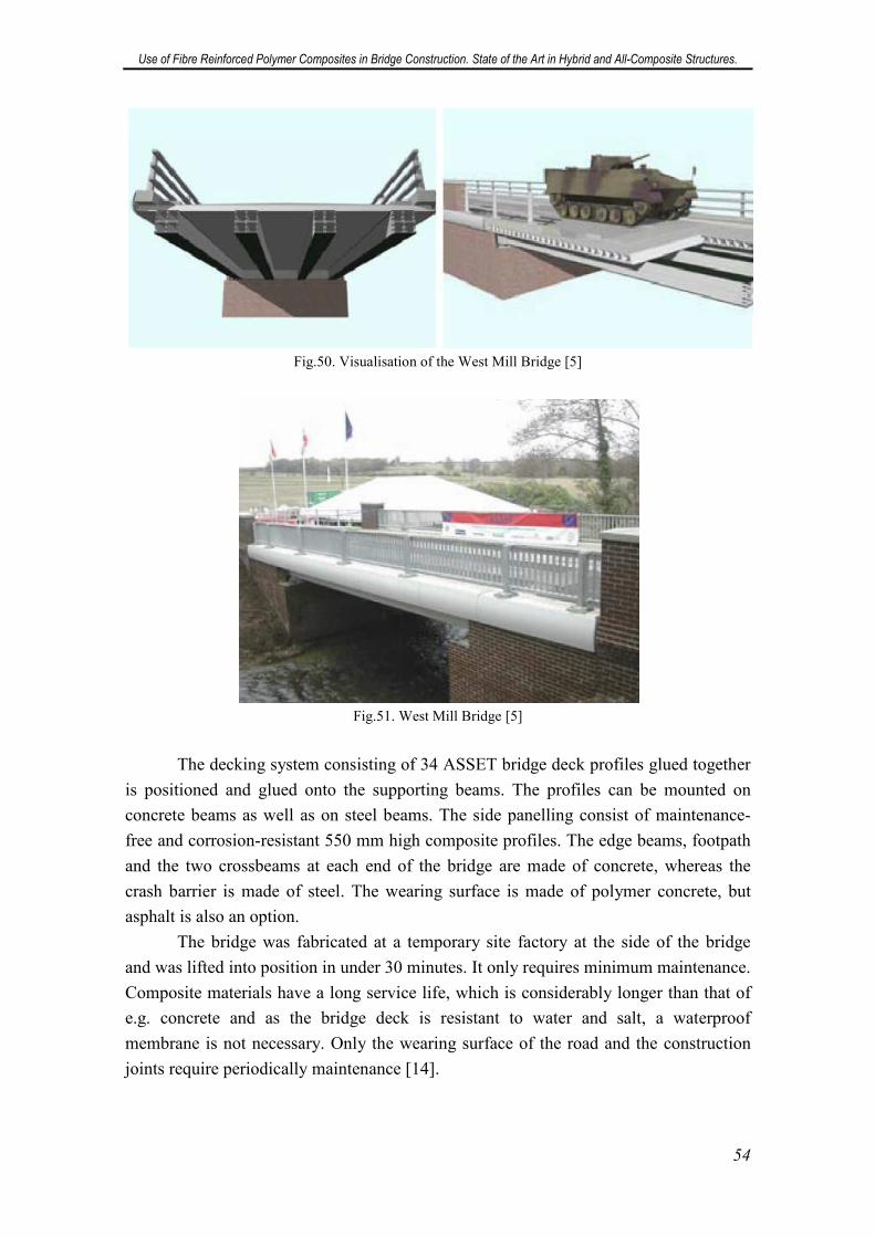
Use of Fibre Reinforced Polymer Composites in Bridge Construction. State of the Art in Hybrid and All-Composite Structures.
54
Fig.50. Visualisation of the West Mill Bridge [5]
Fig.51. West Mill Bridge [5]
The decking system consisting of 34 ASSET bridge deck profiles glued together
is positioned and glued onto the supporting beams. The profiles can be mounted on
concrete beams as well as on steel beams. The side panelling consist of maintenance-
free and corrosion-resistant 550 mm high composite profiles. The edge beams, footpath
and the two crossbeams at each end of the bridge are made of concrete, whereas the
crash barrier is made of steel. The wearing surface is made of polymer concrete, but
asphalt is also an option.
The bridge was fabricated at a temporary site factory at the side of the bridge
and was lifted into position in under 30 minutes. It only requires minimum maintenance.
Composite materials have a long service life, which is considerably longer than that of
e.g. concrete and as the bridge deck is resistant to water and salt, a waterproof
membrane is not necessary. Only the wearing surface of the road and the construction
joints require periodically maintenance [14].
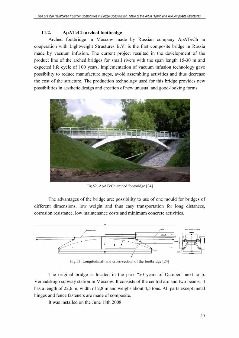
Use of Fibre Reinforced Polymer Composites in Bridge Construction. State of the Art in Hybrid and All-Composite Structures.
55
11.2. ApATeCh arched footbridge
Arched footbridge in Moscow made by Russian company ApATeCh in
cooperation with Lightweight Structures B.V. is the first composite bridge in Russia
made by vacuum infusion. The current project resulted in the development of the
product line of the arched bridges for small rivers with the span length 15-30 m and
expected life cycle of 100 years. Implementation of vacuum infusion technology gave
possibility to reduce manufacture steps, avoid assembling activities and thus decrease
the cost of the structure. The production technology used for this bridge provides new
possibilities in aesthetic design and creation of new unusual and good-looking forms.
Fig.52. ApATeCh arched footbridge [24]
The advantages of the bridge are: possibility to use of one mould for bridges of
different dimensions, low weight and thus easy transportation for long distances,
corrosion resistance, low maintenance costs and minimum concrete activities.
Fig.53. Longitudinal- and cross-section of the footbridge [24]
The original bridge is located in the park "50 years of October" next to p.
Vernadskogo subway station in Moscow. It consists of the central arc and two beams. It
has a length of 22,6 m, width of 2,8 m and weighs about 4,5 tons. All parts except metal
hinges and fence fasteners are made of composite.
It was installed on the June 18th 2008.
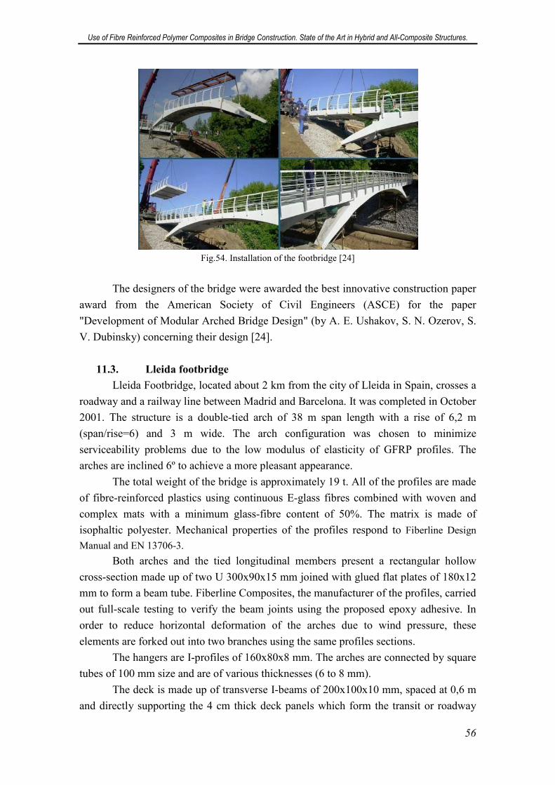
Use of Fibre Reinforced Polymer Composites in Bridge Construction. State of the Art in Hybrid and All-Composite Structures.
56
Fig.54. Installation of the footbridge [24]
The designers of the bridge were awarded the best innovative construction paper
award from the American Society of Civil Engineers (ASCE) for the paper
"Development of Modular Arched Bridge Design" (by A. E. Ushakov, S. N. Ozerov, S.
V. Dubinsky) concerning their design [24].
11.3. Lleida footbridge
Lleida Footbridge, located about 2 km from the city of Lleida in Spain, crosses a
roadway and a railway line between Madrid and Barcelona. It was completed in October
2001. The structure is a double-tied arch of 38 m span length with a rise of 6,2 m
(span/rise=6) and 3 m wide. The arch configuration was chosen to minimize
serviceability problems due to the low modulus of elasticity of GFRP profiles. The
arches are inclined 6º to achieve a more pleasant appearance.
The total weight of the bridge is approximately 19 t. All of the profiles are made
of fibre-reinforced plastics using continuous E-glass fibres combined with woven and
complex mats with a minimum glass-fibre content of 50%. The matrix is made of
isophaltic polyester. Mechanical properties of the profiles respond to Fiberline Design
Manual and EN 13706-3.
Both arches and the tied longitudinal members present a rectangular hollow
cross-section made up of two U 300x90x15 mm joined with glued flat plates of 180x12
mm to form a beam tube. Fiberline Composites, the manufacturer of the profiles, carried
out full-scale testing to verify the beam joints using the proposed epoxy adhesive. In
order to reduce horizontal deformation of the arches due to wind pressure, these
elements are forked out into two branches using the same profiles sections.
The hangers are I-profiles of 160x80x8 mm. The arches are connected by square
tubes of 100 mm size and are of various thicknesses (6 to 8 mm).
The deck is made up of transverse I-beams of 200x100x10 mm, spaced at 0,6 m
and directly supporting the 4 cm thick deck panels which form the transit or roadway
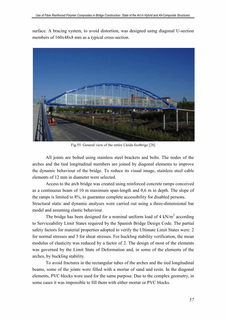
Use of Fibre Reinforced Polymer Composites in Bridge Construction. State of the Art in Hybrid and All-Composite Structures.
57
surface. A bracing system, to avoid distortion, was designed using diagonal U-section
members of 160x48x8 mm as a typical cross-section.
Fig.55. General view of the entire Lleida footbrige [28]
All joints are bolted using stainless steel brackets and bolts. The nodes of the
arches and the tied longitudinal members are joined by diagonal elements to improve
the dynamic behaviour of the bridge. To reduce its visual image, stainless steel cable
elements of 12 mm in diameter were selected.
Access to the arch bridge was created using reinforced concrete ramps conceived
as a continuous beam of 10 m maximum span-length and 0,6 m in depth. The slope of
the ramps is limited to 8%, to guarantee complete accessibility for disabled persons.
Structural static and dynamic analyses were carried out using a three-dimensional bar
model and assuming elastic behaviour.
The bridge has been designed for a nominal uniform load of 4 kN/m2 according
to Serviceability Limit States required by the Spanish Bridge Design Code. The partial
safety factors for material properties adopted to verify the Ultimate Limit States were: 2
for normal stresses and 3 for shear stresses. For buckling stability verification, the mean
modulus of elasticity was reduced by a factor of 2. The design of most of the elements
was governed by the Limit State of Deformation and, in some of the elements of the
arches, by buckling stability.
To avoid fractures in the rectangular tubes of the arches and the tied longitudinal
beams, some of the joints were filled with a mortar of sand and resin. In the diagonal
elements, PVC blocks were used for the same purpose. Due to the complex geometry, in
some cases it was impossible to fill them with either mortar or PVC blocks.
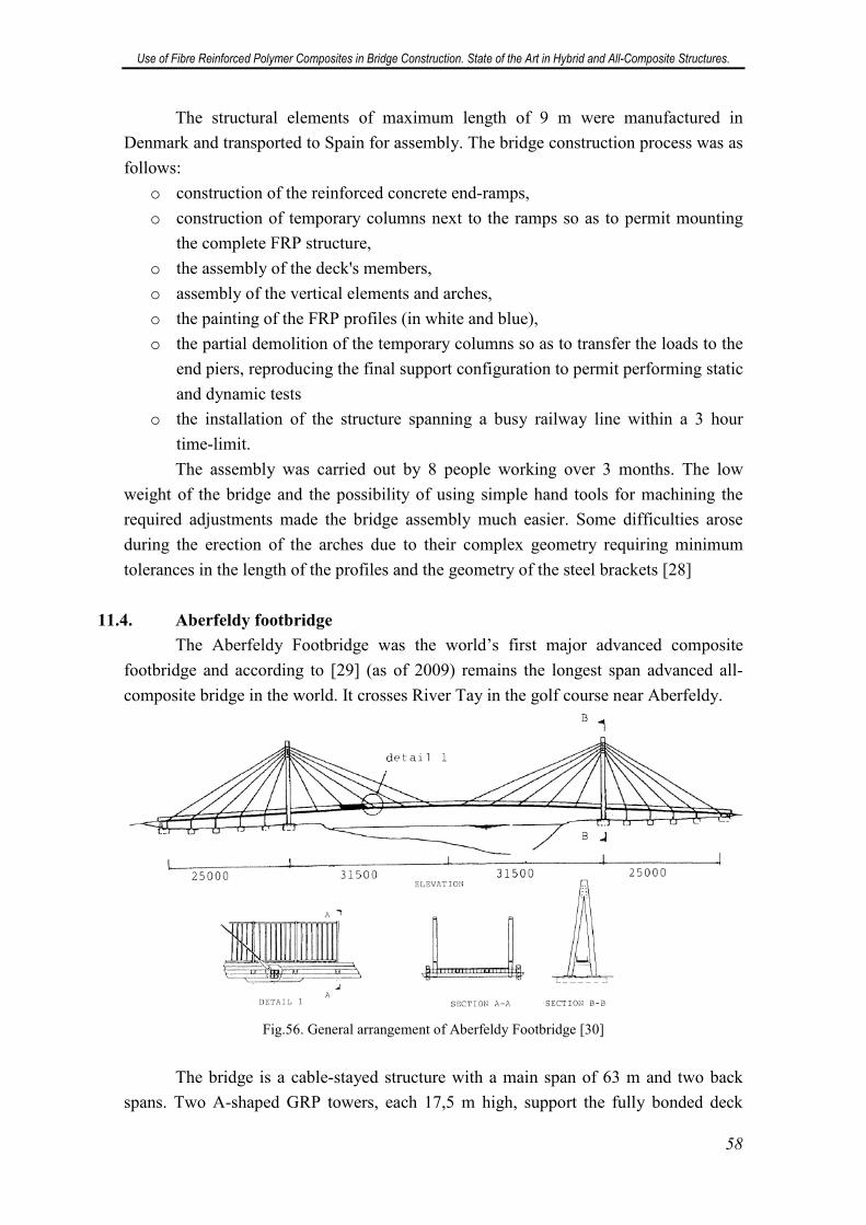
Use of Fibre Reinforced Polymer Composites in Bridge Construction. State of the Art in Hybrid and All-Composite Structures.
58
The structural elements of maximum length of 9 m were manufactured in
Denmark and transported to Spain for assembly. The bridge construction process was as
follows:
o construction of the reinforced concrete end-ramps,
o construction of temporary columns next to the ramps so as to permit mounting
the complete FRP structure,
o the assembly of the deck's members,
o assembly of the vertical elements and arches,
o the painting of the FRP profiles (in white and blue),
o the partial demolition of the temporary columns so as to transfer the loads to the
end piers, reproducing the final support configuration to permit performing static
and dynamic tests
o the installation of the structure spanning a busy railway line within a 3 hour
time-limit.
The assembly was carried out by 8 people working over 3 months. The low
weight of the bridge and the possibility of using simple hand tools for machining the
required adjustments made the bridge assembly much easier. Some difficulties arose
during the erection of the arches due to their complex geometry requiring minimum
tolerances in the length of the profiles and the geometry of the steel brackets [28]
11.4. Aberfeldy footbridge
The Aberfeldy Footbridge was the world’s first major advanced composite
footbridge and according to [29] (as of 2009) remains the longest span advanced all-
composite bridge in the world. It crosses River Tay in the golf course near Aberfeldy.
Fig.56. General arrangement of Aberfeldy Footbridge [30]
The bridge is a cable-stayed structure with a main span of 63 m and two back
spans. Two A-shaped GRP towers, each 17,5 m high, support the fully bonded deck
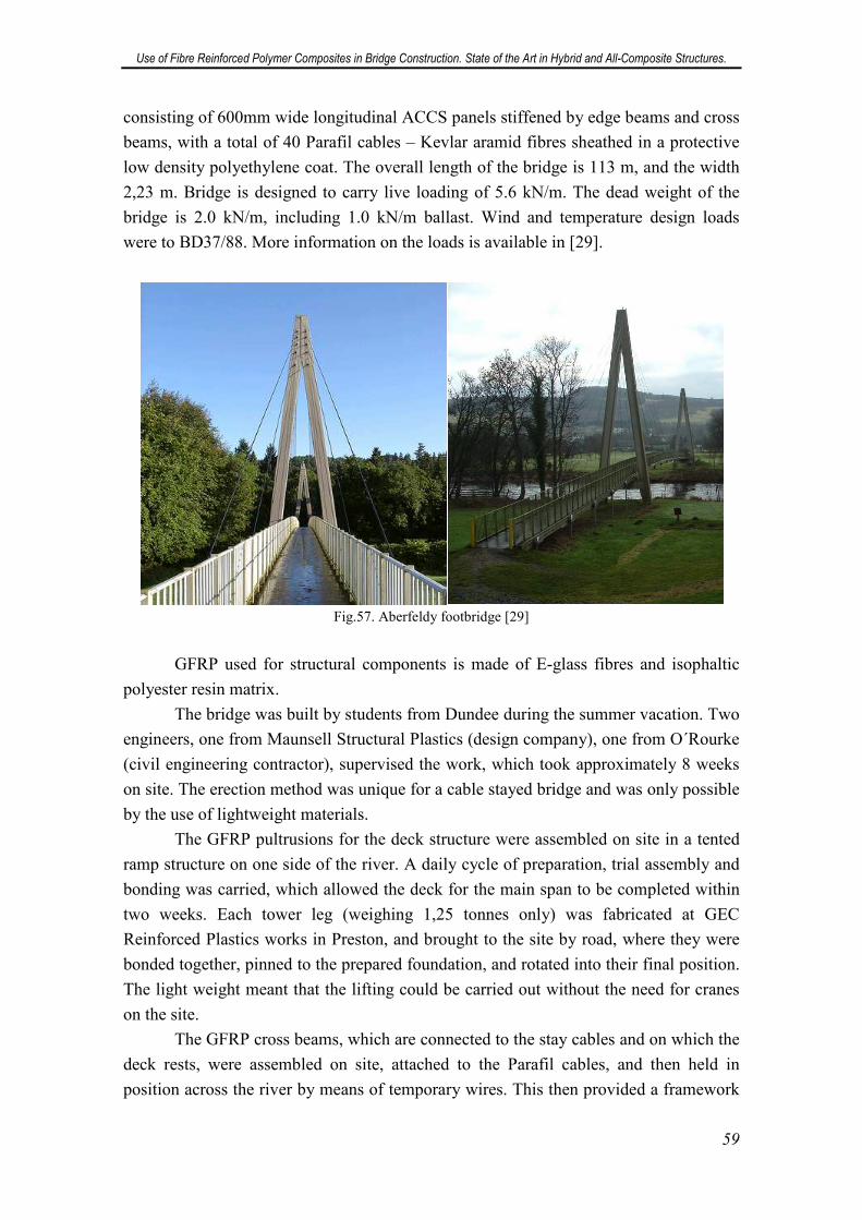
Use of Fibre Reinforced Polymer Composites in Bridge Construction. State of the Art in Hybrid and All-Composite Structures.
59
consisting of 600mm wide longitudinal ACCS panels stiffened by edge beams and cross
beams, with a total of 40 Parafil cables – Kevlar aramid fibres sheathed in a protective
low density polyethylene coat. The overall length of the bridge is 113 m, and the width
2,23 m. Bridge is designed to carry live loading of 5.6 kN/m. The dead weight of the
bridge is 2.0 kN/m, including 1.0 kN/m ballast. Wind and temperature design loads
were to BD37/88. More information on the loads is available in [29].
Fig.57. Aberfeldy footbridge [29]
GFRP used for structural components is made of E-glass fibres and isophaltic
polyester resin matrix.
The bridge was built by students from Dundee during the summer vacation. Two
engineers, one from Maunsell Structural Plastics (design company), one from O´Rourke
(civil engineering contractor), supervised the work, which took approximately 8 weeks
on site. The erection method was unique for a cable stayed bridge and was only possible
by the use of lightweight materials.
The GFRP pultrusions for the deck structure were assembled on site in a tented
ramp structure on one side of the river. A daily cycle of preparation, trial assembly and
bonding was carried, which allowed the deck for the main span to be completed within
two weeks. Each tower leg (weighing 1,25 tonnes only) was fabricated at GEC
Reinforced Plastics works in Preston, and brought to the site by road, where they were
bonded together, pinned to the prepared foundation, and rotated into their final position.
The light weight meant that the lifting could be carried out without the need for cranes
on the site.
The GFRP cross beams, which are connected to the stay cables and on which the
deck rests, were assembled on site, attached to the Parafil cables, and then held in
position across the river by means of temporary wires. This then provided a framework
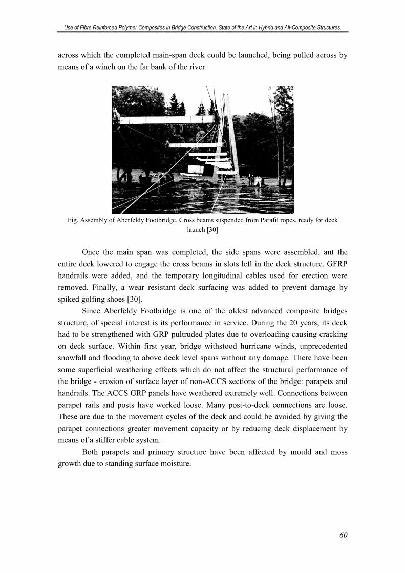
Use of Fibre Reinforced Polymer Composites in Bridge Construction. State of the Art in Hybrid and All-Composite Structures.
60
across which the completed main-span deck could be launched, being pulled across by
means of a winch on the far bank of the river.
Fig. Assembly of Aberfeldy Footbridge. Cross beams suspended from Parafil ropes, ready for deck
launch [30]
Once the main span was completed, the side spans were assembled, ant the
entire deck lowered to engage the cross beams in slots left in the deck structure. GFRP
handrails were added, and the temporary longitudinal cables used for erection were
removed. Finally, a wear resistant deck surfacing was added to prevent damage by
spiked golfing shoes [30].
Since Aberfeldy Footbridge is one of the oldest advanced composite bridges
structure, of special interest is its performance in service. During the 20 years, its deck
had to be strengthened with GRP pultruded plates due to overloading causing cracking
on deck surface. Within first year, bridge withstood hurricane winds, unprecedented
snowfall and flooding to above deck level spans without any damage. There have been
some superficial weathering effects which do not affect the structural performance of
the bridge - erosion of surface layer of non-ACCS sections of the bridge: parapets and
handrails. The ACCS GRP panels have weathered extremely well. Connections between
parapet rails and posts have worked loose. Many post-to-deck connections are loose.
These are due to the movement cycles of the deck and could be avoided by giving the
parapet connections greater movement capacity or by reducing deck displacement by
means of a stiffer cable system.
Both parapets and primary structure have been affected by mould and moss
growth due to standing surface moisture.
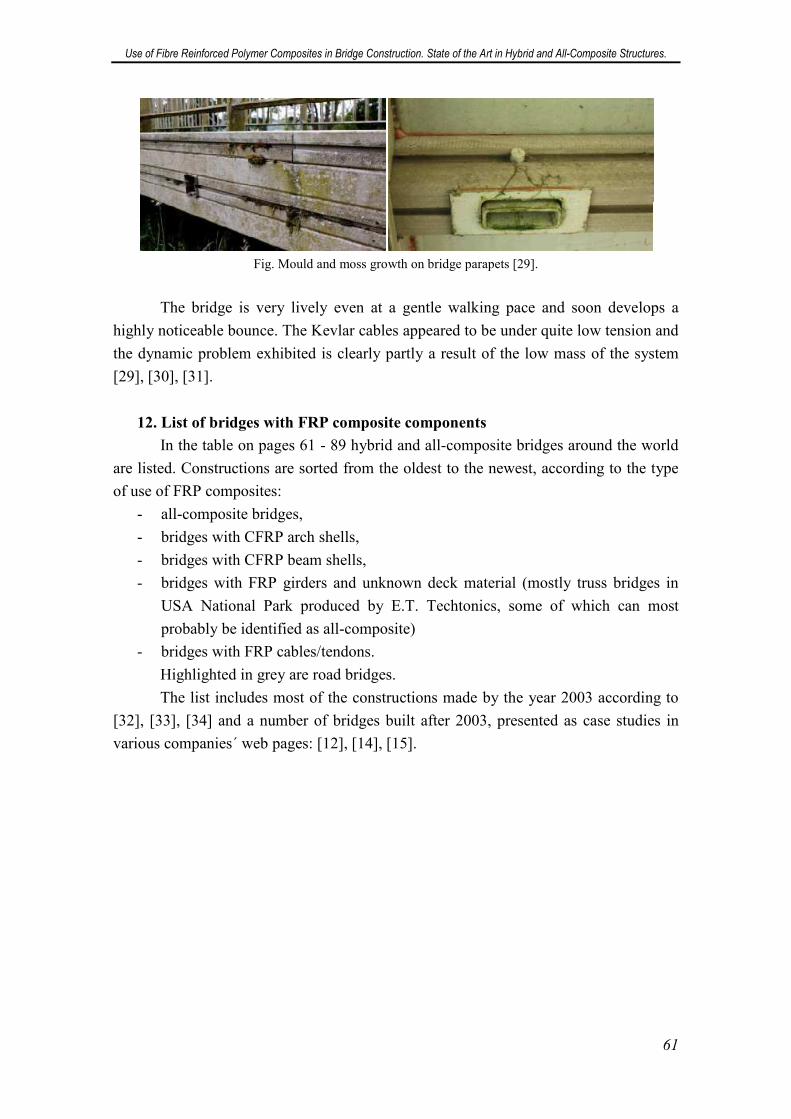
Use of Fibre Reinforced Polymer Composites in Bridge Construction. State of the Art in Hybrid and All-Composite Structures.
61
Fig. Mould and moss growth on bridge parapets [29].
The bridge is very lively even at a gentle walking pace and soon develops a
highly noticeable bounce. The Kevlar cables appeared to be under quite low tension and
the dynamic problem exhibited is clearly partly a result of the low mass of the system
[29], [30], [31].
12. List of bridges with FRP composite components
In the table on pages 61 - 89 hybrid and all-composite bridges around the world
are listed. Constructions are sorted from the oldest to the newest, according to the type
of use of FRP composites:
- all-composite bridges,
- bridges with CFRP arch shells,
- bridges with CFRP beam shells,
- bridges with FRP girders and unknown deck material (mostly truss bridges in
USA National Park produced by E.T. Techtonics, some of which can most
probably be identified as all-composite)
- bridges with FRP cables/tendons.
Highlighted in grey are road bridges.
The list includes most of the constructions made by the year 2003 according to
[32], [33], [34] and a number of bridges built after 2003, presented as case studies in
various companies´ web pages: [12], [14], [15].
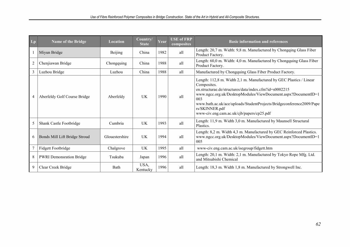
Use of Fibre Reinforced Polymer Composites in Bridge Construction. State of the Art in Hybrid and All-Composite Structures.
62
Lp Name of the Bridge Location Country/
State Year
USE of FRP
composites Basic information and references
1 Miyun Bridge Beijing China 1982 all Length: 20,7 m. Width: 9,8 m. Manufactured by Chongqing Glass Fiber Product Factory.
2 Chenjiawan Bridge Chongquing China 1988 all Length: 60,0 m. Width: 4,0 m. Manufactured by Chongquing Glass Fiber Product Factory.
3 Luzhou Bridge Luzhou China 1988 all Manufactured by Chongquing Glass Fiber Product Factory.
4 Aberfeldy Golf Course Bridge Aberfeldy UK 1990 all
Length: 112,8 m. Width 2,1 m. Manufactured by GEC Plastics / Linear Composites. en.structurae.de/structures/data/index.cfm?id=s0002215 www.ngcc.org.uk/DesktopModules/ViewDocument.aspx?DocumentID=1003 www.bath.ac.uk/ace/uploads/StudentProjects/Bridgeconference2009/Papers/SKINNER.pdf www-civ.eng.cam.ac.uk/cjb/papers/cp25.pdf
5 Shank Castle Footbridge Cumbria UK 1993 all Length: 11,9 m. Width 3,0 m. Manufactured by Maunsell Structural Plastics.
6 Bonds Mill Lift Bridge Stroud Glouestershire UK 1994 all Length: 8,2 m. Width 4,3 m. Manufactured by GEC Reinforced Plastics. www.ngcc.org.uk/DesktopModules/ViewDocument.aspx?DocumentID=1005
7 Fidgett Footbridge Chalgrove UK 1995 all www-civ.eng.cam.ac.uk/isegroup/fidgett.htm
8 PWRI Demonsration Bridge Tsukuba Japan 1996 all Length: 20,1 m. Width: 2,1 m. Manufactured by Tokyo Rope Mfg. Ltd. and Mitsubishi Chemical
9 Clear Creek Bridge Bath USA,
Kentucky 1996 all Length: 18,3 m. Width 1,8 m. Manufactured by Strongwell Inc.
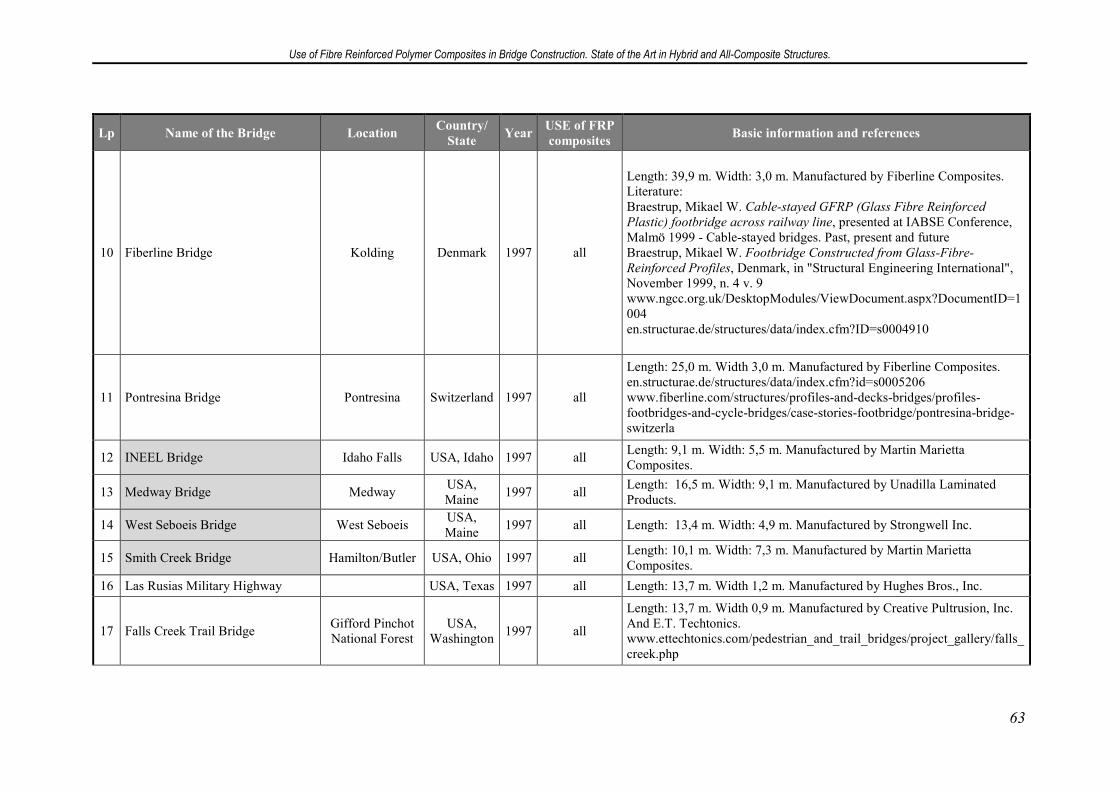
Use of Fibre Reinforced Polymer Composites in Bridge Construction. State of the Art in Hybrid and All-Composite Structures.
63
Lp Name of the Bridge Location Country/
State Year
USE of FRP
composites Basic information and references
10 Fiberline Bridge Kolding Denmark 1997 all
Length: 39,9 m. Width: 3,0 m. Manufactured by Fiberline Composites. Literature: Braestrup, Mikael W. Cable-stayed GFRP (Glass Fibre Reinforced
Plastic) footbridge across railway line, presented at IABSE Conference, Malmö 1999 - Cable-stayed bridges. Past, present and future Braestrup, Mikael W. Footbridge Constructed from Glass-Fibre-
Reinforced Profiles, Denmark, in "Structural Engineering International", November 1999, n. 4 v. 9 www.ngcc.org.uk/DesktopModules/ViewDocument.aspx?DocumentID=1004 en.structurae.de/structures/data/index.cfm?ID=s0004910
11 Pontresina Bridge Pontresina Switzerland 1997 all
Length: 25,0 m. Width 3,0 m. Manufactured by Fiberline Composites. en.structurae.de/structures/data/index.cfm?id=s0005206 www.fiberline.com/structures/profiles-and-decks-bridges/profiles-footbridges-and-cycle-bridges/case-stories-footbridge/pontresina-bridge-switzerla
12 INEEL Bridge Idaho Falls USA, Idaho 1997 all Length: 9,1 m. Width: 5,5 m. Manufactured by Martin Marietta Composites.
13 Medway Bridge Medway USA, Maine
1997 all Length: 16,5 m. Width: 9,1 m. Manufactured by Unadilla Laminated Products.
14 West Seboeis Bridge West Seboeis USA, Maine
1997 all Length: 13,4 m. Width: 4,9 m. Manufactured by Strongwell Inc.
15 Smith Creek Bridge Hamilton/Butler USA, Ohio 1997 all Length: 10,1 m. Width: 7,3 m. Manufactured by Martin Marietta Composites.
16 Las Rusias Military Highway USA, Texas 1997 all Length: 13,7 m. Width 1,2 m. Manufactured by Hughes Bros., Inc.
17 Falls Creek Trail Bridge Gifford Pinchot National Forest
USA, Washington
1997 all
Length: 13,7 m. Width 0,9 m. Manufactured by Creative Pultrusion, Inc. And E.T. Techtonics. www.ettechtonics.com/pedestrian_and_trail_bridges/project_gallery/falls_creek.php
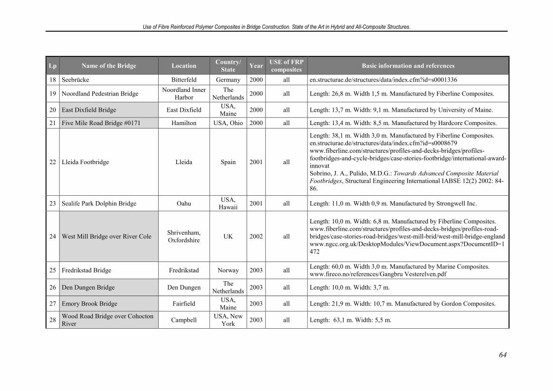
Use of Fibre Reinforced Polymer Composites in Bridge Construction. State of the Art in Hybrid and All-Composite Structures.
64
Lp Name of the Bridge Location Country/
State Year
USE of FRP
composites Basic information and references
18 Seebrücke Bitterfeld Germany 2000 all en.structurae.de/structures/data/index.cfm?id=s0001336
19 Noordland Pedestrian Bridge Noordland Inner
Harbor The
Netherlands 2000 all Length: 26,8 m. Width 1,5 m. Manufactured by Fiberline Composites.
20 East Dixfield Bridge East Dixfield USA, Maine
2000 all Length: 13,7 m. Width: 9,1 m. Manufactured by University of Maine.
21 Five Mile Road Bridge #0171 Hamilton USA, Ohio 2000 all Length: 13,4 m. Width: 8,5 m. Manufactured by Hardcore Composites.
22 Lleida Footbridge Lleida Spain 2001 all
Length: 38,1 m. Width 3,0 m. Manufactured by Fiberline Composites. en.structurae.de/structures/data/index.cfm?id=s0008679 www.fiberline.com/structures/profiles-and-decks-bridges/profiles-footbridges-and-cycle-bridges/case-stories-footbridge/international-award-innovat Sobrino, J. A., Pulido, M.D.G.: Towards Advanced Composite Material
Footbridges, Structural Engineering International IABSE 12(2) 2002: 84-86.
23 Sealife Park Dolphin Bridge Oahu USA,
Hawaii 2001 all Length: 11,0 m. Width 0,9 m. Manufactured by Strongwell Inc.
24 West Mill Bridge over River Cole Shrivenham, Oxfordshire
UK 2002 all
Length: 10,0 m. Width: 6,8 m. Manufactured by Fiberline Composites. www.fiberline.com/structures/profiles-and-decks-bridges/profiles-road-bridges/case-stories-road-bridges/west-mill-brid/west-mill-bridge-england www.ngcc.org.uk/DesktopModules/ViewDocument.aspx?DocumentID=1472
25 Fredrikstad Bridge Fredrikstad Norway 2003 all Length: 60,0 m. Width 3,0 m. Manufactured by Marine Composites. www.fireco.no/references/Gangbru Vesterelven.pdf
26 Den Dungen Bridge Den Dungen The
Netherlands 2003 all Length: 10,0 m. Width: 3,7 m.
27 Emory Brook Bridge Fairfield USA, Maine
2003 all Length: 21,9 m. Width: 10,7 m. Manufactured by Gordon Composites.
28 Wood Road Bridge over Cohocton River
Campbell USA, New
York 2003 all Length: 63,1 m. Width: 5,5 m.
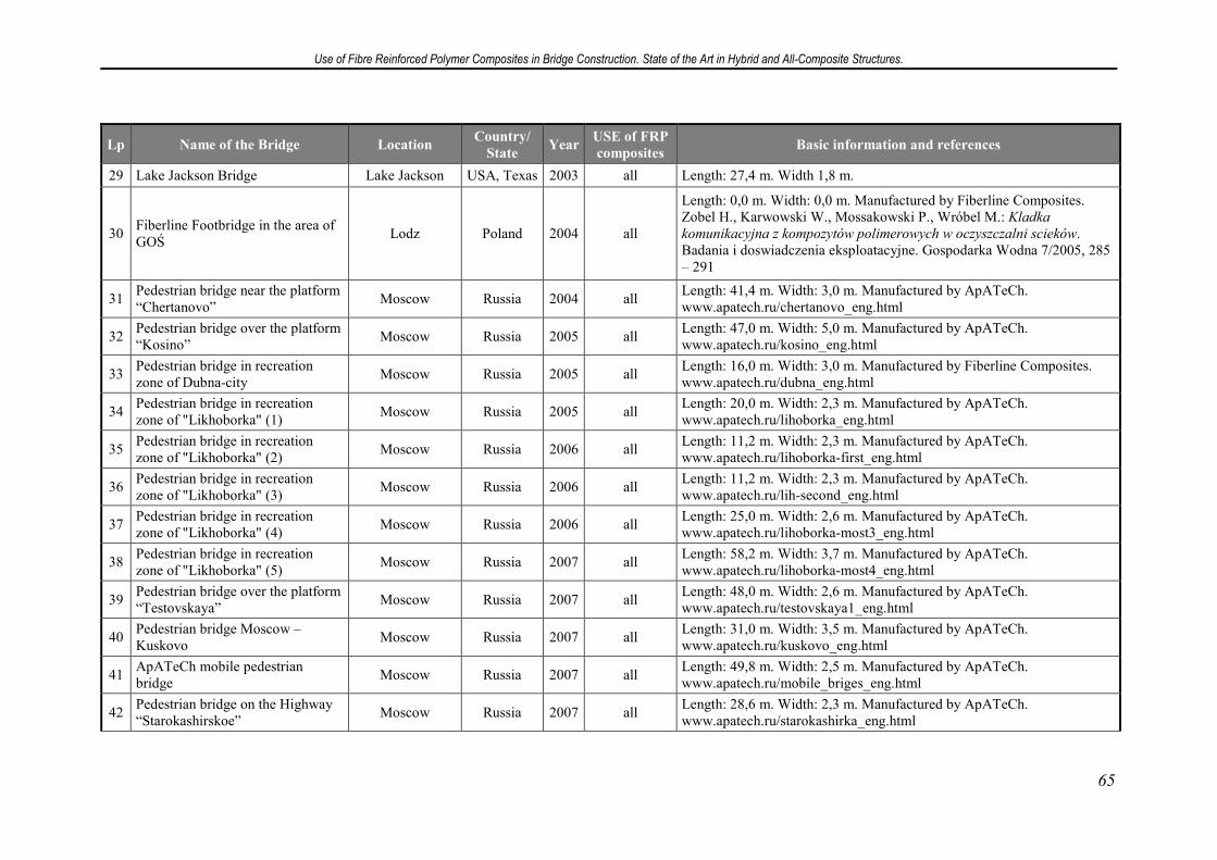
Use of Fibre Reinforced Polymer Composites in Bridge Construction. State of the Art in Hybrid and All-Composite Structures.
65
Lp Name of the Bridge Location Country/
State Year
USE of FRP
composites Basic information and references
29 Lake Jackson Bridge Lake Jackson USA, Texas 2003 all Length: 27,4 m. Width 1,8 m.
30 Fiberline Footbridge in the area of GOŚ
Lodz Poland 2004 all
Length: 0,0 m. Width: 0,0 m. Manufactured by Fiberline Composites. Zobel H., Karwowski W., Mossakowski P., Wróbel M.: Kladka
komunikacyjna z kompozytów polimerowych w oczyszczalni scieków. Badania i doswiadczenia eksploatacyjne. Gospodarka Wodna 7/2005, 285 – 291
31 Pedestrian bridge near the platform “Chertanovo”
Moscow Russia 2004 all Length: 41,4 m. Width: 3,0 m. Manufactured by ApATeCh. www.apatech.ru/chertanovo_eng.html
32 Pedestrian bridge over the platform “Kosino”
Moscow Russia 2005 all Length: 47,0 m. Width: 5,0 m. Manufactured by ApATeCh. www.apatech.ru/kosino_eng.html
33 Pedestrian bridge in recreation zone of Dubna-city
Moscow Russia 2005 all Length: 16,0 m. Width: 3,0 m. Manufactured by Fiberline Composites. www.apatech.ru/dubna_eng.html
34 Pedestrian bridge in recreation zone of "Likhoborka" (1)
Moscow Russia 2005 all Length: 20,0 m. Width: 2,3 m. Manufactured by ApATeCh. www.apatech.ru/lihoborka_eng.html
35 Pedestrian bridge in recreation zone of "Likhoborka" (2)
Moscow Russia 2006 all Length: 11,2 m. Width: 2,3 m. Manufactured by ApATeCh. www.apatech.ru/lihoborka-first_eng.html
36 Pedestrian bridge in recreation zone of "Likhoborka" (3)
Moscow Russia 2006 all Length: 11,2 m. Width: 2,3 m. Manufactured by ApATeCh. www.apatech.ru/lih-second_eng.html
37 Pedestrian bridge in recreation zone of "Likhoborka" (4)
Moscow Russia 2006 all Length: 25,0 m. Width: 2,6 m. Manufactured by ApATeCh. www.apatech.ru/lihoborka-most3_eng.html
38 Pedestrian bridge in recreation zone of "Likhoborka" (5)
Moscow Russia 2007 all Length: 58,2 m. Width: 3,7 m. Manufactured by ApATeCh. www.apatech.ru/lihoborka-most4_eng.html
39 Pedestrian bridge over the platform “Testovskaya”
Moscow Russia 2007 all Length: 48,0 m. Width: 2,6 m. Manufactured by ApATeCh. www.apatech.ru/testovskaya1_eng.html
40 Pedestrian bridge Moscow – Kuskovo
Moscow Russia 2007 all Length: 31,0 m. Width: 3,5 m. Manufactured by ApATeCh. www.apatech.ru/kuskovo_eng.html
41 ApATeCh mobile pedestrian bridge
Moscow Russia 2007 all Length: 49,8 m. Width: 2,5 m. Manufactured by ApATeCh. www.apatech.ru/mobile_briges_eng.html
42 Pedestrian bridge on the Highway “Starokashirskoe”
Moscow Russia 2007 all Length: 28,6 m. Width: 2,3 m. Manufactured by ApATeCh. www.apatech.ru/starokashirka_eng.html
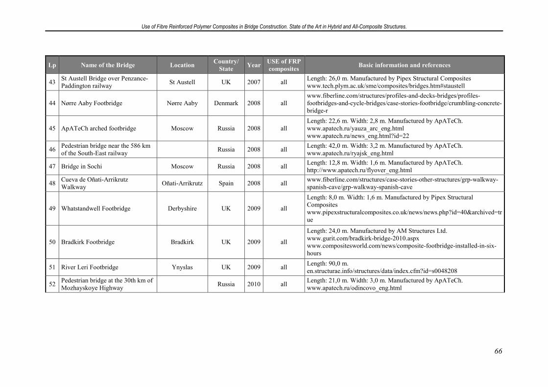
Use of Fibre Reinforced Polymer Composites in Bridge Construction. State of the Art in Hybrid and All-Composite Structures.
66
Lp Name of the Bridge Location Country/
State Year
USE of FRP
composites Basic information and references
43 St Austell Bridge over Penzance-Paddington railway
St Austell UK 2007 all Length: 26,0 m. Manufactured by Pipex Structural Composites www.tech.plym.ac.uk/sme/composites/bridges.htm#staustell
44 Nørre Aaby Footbridge Nørre Aaby Denmark 2008 all www.fiberline.com/structures/profiles-and-decks-bridges/profiles-footbridges-and-cycle-bridges/case-stories-footbridge/crumbling-concrete-bridge-r
45 ApATeCh arched footbridge Moscow Russia 2008 all Length: 22,6 m. Width: 2,8 m. Manufactured by ApATeCh. www.apatech.ru/yauza_arc_eng.html www.apatech.ru/news_eng.html?id=22
46 Pedestrian bridge near the 586 km of the South-East railway
Russia 2008 all Length: 42,0 m. Width: 3,2 m. Manufactured by ApATeCh. www.apatech.ru/ryajsk_eng.html
47 Bridge in Sochi Moscow Russia 2008 all Length: 12,8 m. Width: 1,6 m. Manufactured by ApATeCh. http://www.apatech.ru/flyover_eng.html
48 Cueva de Oñati-Arrikrutz Walkway
Oñati-Arrikrutz Spain 2008 all www.fiberline.com/structures/case-stories-other-structures/grp-walkway-spanish-cave/grp-walkway-spanish-cave
49 Whatstandwell Footbridge Derbyshire UK 2009 all
Length: 8,0 m. Width: 1,6 m. Manufactured by Pipex Structural Composites www.pipexstructuralcomposites.co.uk/news/news.php?id=40&archived=true
50 Bradkirk Footbridge Bradkirk UK 2009 all
Length: 24,0 m. Manufactured by AM Structures Ltd. www.gurit.com/bradkirk-bridge-2010.aspx www.compositesworld.com/news/composite-footbridge-installed-in-six-hours
51 River Leri Footbridge Ynyslas UK 2009 all Length: 90,0 m. en.structurae.info/structures/data/index.cfm?id=s0048208
52 Pedestrian bridge at the 30th km of Mozhayskoye Highway
Russia 2010 all Length: 21,0 m. Width: 3,0 m. Manufactured by ApATeCh. www.apatech.ru/odincovo_eng.html
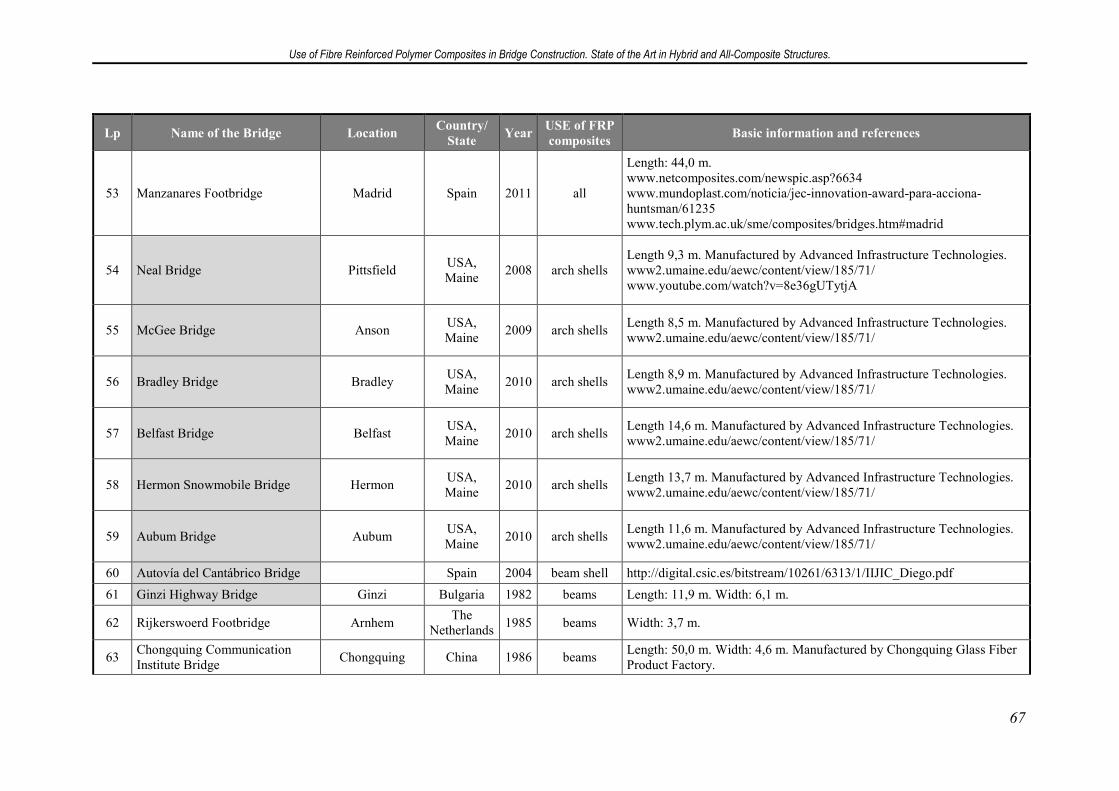
Use of Fibre Reinforced Polymer Composites in Bridge Construction. State of the Art in Hybrid and All-Composite Structures.
67
Lp Name of the Bridge Location Country/
State Year
USE of FRP
composites Basic information and references
53 Manzanares Footbridge Madrid Spain 2011 all
Length: 44,0 m. www.netcomposites.com/newspic.asp?6634 www.mundoplast.com/noticia/jec-innovation-award-para-acciona-huntsman/61235 www.tech.plym.ac.uk/sme/composites/bridges.htm#madrid
54 Neal Bridge Pittsfield USA, Maine
2008 arch shells Length 9,3 m. Manufactured by Advanced Infrastructure Technologies. www2.umaine.edu/aewc/content/view/185/71/ www.youtube.com/watch?v=8e36gUTytjA
55 McGee Bridge Anson USA, Maine
2009 arch shells Length 8,5 m. Manufactured by Advanced Infrastructure Technologies. www2.umaine.edu/aewc/content/view/185/71/
56 Bradley Bridge Bradley USA, Maine
2010 arch shells Length 8,9 m. Manufactured by Advanced Infrastructure Technologies. www2.umaine.edu/aewc/content/view/185/71/
57 Belfast Bridge Belfast USA, Maine
2010 arch shells Length 14,6 m. Manufactured by Advanced Infrastructure Technologies. www2.umaine.edu/aewc/content/view/185/71/
58 Hermon Snowmobile Bridge Hermon USA, Maine
2010 arch shells Length 13,7 m. Manufactured by Advanced Infrastructure Technologies. www2.umaine.edu/aewc/content/view/185/71/
59 Aubum Bridge Aubum USA, Maine
2010 arch shells Length 11,6 m. Manufactured by Advanced Infrastructure Technologies. www2.umaine.edu/aewc/content/view/185/71/
60 Autovía del Cantábrico Bridge Spain 2004 beam shell http://digital.csic.es/bitstream/10261/6313/1/IIJIC_Diego.pdf
61 Ginzi Highway Bridge Ginzi Bulgaria 1982 beams Length: 11,9 m. Width: 6,1 m.
62 Rijkerswoerd Footbridge Arnhem The
Netherlands 1985 beams Width: 3,7 m.
63 Chongquing Communication Institute Bridge
Chongquing China 1986 beams Length: 50,0 m. Width: 4,6 m. Manufactured by Chongquing Glass Fiber Product Factory.
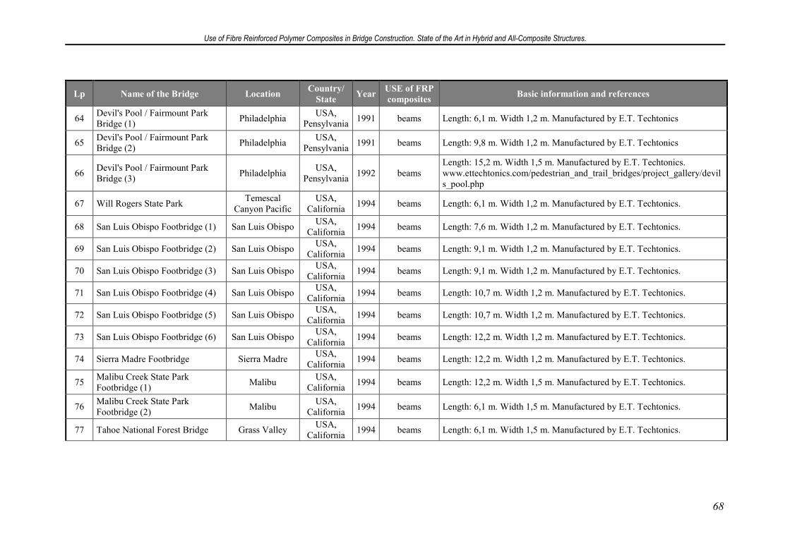
Use of Fibre Reinforced Polymer Composites in Bridge Construction. State of the Art in Hybrid and All-Composite Structures.
68
Lp Name of the Bridge Location Country/
State Year
USE of FRP
composites Basic information and references
64 Devil's Pool / Fairmount Park Bridge (1)
Philadelphia USA,
Pensylvania 1991 beams Length: 6,1 m. Width 1,2 m. Manufactured by E.T. Techtonics
65 Devil's Pool / Fairmount Park Bridge (2)
Philadelphia USA,
Pensylvania 1991 beams Length: 9,8 m. Width 1,2 m. Manufactured by E.T. Techtonics
66 Devil's Pool / Fairmount Park Bridge (3)
Philadelphia USA,
Pensylvania 1992 beams
Length: 15,2 m. Width 1,5 m. Manufactured by E.T. Techtonics. www.ettechtonics.com/pedestrian_and_trail_bridges/project_gallery/devils_pool.php
67 Will Rogers State Park Temescal
Canyon Pacific USA,
California 1994 beams Length: 6,1 m. Width 1,2 m. Manufactured by E.T. Techtonics.
68 San Luis Obispo Footbridge (1) San Luis Obispo USA,
California 1994 beams Length: 7,6 m. Width 1,2 m. Manufactured by E.T. Techtonics.
69 San Luis Obispo Footbridge (2) San Luis Obispo USA,
California 1994 beams Length: 9,1 m. Width 1,2 m. Manufactured by E.T. Techtonics.
70 San Luis Obispo Footbridge (3) San Luis Obispo USA,
California 1994 beams Length: 9,1 m. Width 1,2 m. Manufactured by E.T. Techtonics.
71 San Luis Obispo Footbridge (4) San Luis Obispo USA,
California 1994 beams Length: 10,7 m. Width 1,2 m. Manufactured by E.T. Techtonics.
72 San Luis Obispo Footbridge (5) San Luis Obispo USA,
California 1994 beams Length: 10,7 m. Width 1,2 m. Manufactured by E.T. Techtonics.
73 San Luis Obispo Footbridge (6) San Luis Obispo USA,
California 1994 beams Length: 12,2 m. Width 1,2 m. Manufactured by E.T. Techtonics.
74 Sierra Madre Footbridge Sierra Madre USA,
California 1994 beams Length: 12,2 m. Width 1,2 m. Manufactured by E.T. Techtonics.
75 Malibu Creek State Park Footbridge (1)
Malibu USA,
California 1994 beams Length: 12,2 m. Width 1,5 m. Manufactured by E.T. Techtonics.
76 Malibu Creek State Park Footbridge (2)
Malibu USA,
California 1994 beams Length: 6,1 m. Width 1,5 m. Manufactured by E.T. Techtonics.
77 Tahoe National Forest Bridge Grass Valley USA,
California 1994 beams Length: 6,1 m. Width 1,5 m. Manufactured by E.T. Techtonics.
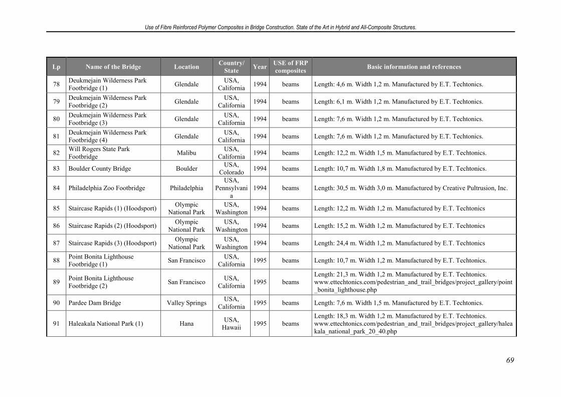
Use of Fibre Reinforced Polymer Composites in Bridge Construction. State of the Art in Hybrid and All-Composite Structures.
69
Lp Name of the Bridge Location Country/
State Year
USE of FRP
composites Basic information and references
78 Deukmejain Wilderness Park Footbridge (1)
Glendale USA,
California 1994 beams Length: 4,6 m. Width 1,2 m. Manufactured by E.T. Techtonics.
79 Deukmejain Wilderness Park Footbridge (2)
Glendale USA,
California 1994 beams Length: 6,1 m. Width 1,2 m. Manufactured by E.T. Techtonics.
80 Deukmejain Wilderness Park Footbridge (3)
Glendale USA,
California 1994 beams Length: 7,6 m. Width 1,2 m. Manufactured by E.T. Techtonics.
81 Deukmejain Wilderness Park Footbridge (4)
Glendale USA,
California 1994 beams Length: 7,6 m. Width 1,2 m. Manufactured by E.T. Techtonics.
82 Will Rogers State Park Footbridge
Malibu USA,
California 1994 beams Length: 12,2 m. Width 1,5 m. Manufactured by E.T. Techtonics.
83 Boulder County Bridge Boulder USA,
Colorado 1994 beams Length: 10,7 m. Width 1,8 m. Manufactured by E.T. Techtonics.
84 Philadelphia Zoo Footbridge Philadelphia USA,
Pennsylvania
1994 beams Length: 30,5 m. Width 3,0 m. Manufactured by Creative Pultrusion, Inc.
85 Staircase Rapids (1) (Hoodsport) Olympic
National Park USA,
Washington 1994 beams Length: 12,2 m. Width 1,2 m. Manufactured by E.T. Techtonics
86 Staircase Rapids (2) (Hoodsport) Olympic
National Park USA,
Washington 1994 beams Length: 15,2 m. Width 1,2 m. Manufactured by E.T. Techtonics
87 Staircase Rapids (3) (Hoodsport) Olympic
National Park USA,
Washington 1994 beams Length: 24,4 m. Width 1,2 m. Manufactured by E.T. Techtonics
88 Point Bonita Lighthouse Footbridge (1)
San Francisco USA,
California 1995 beams Length: 10,7 m. Width 1,2 m. Manufactured by E.T. Techtonics.
89 Point Bonita Lighthouse Footbridge (2)
San Francisco USA,
California 1995 beams
Length: 21,3 m. Width 1,2 m. Manufactured by E.T. Techtonics. www.ettechtonics.com/pedestrian_and_trail_bridges/project_gallery/point_bonita_lighthouse.php
90 Pardee Dam Bridge Valley Springs USA,
California 1995 beams Length: 7,6 m. Width 1,5 m. Manufactured by E.T. Techtonics.
91 Haleakala National Park (1) Hana USA,
Hawaii 1995 beams
Length: 18,3 m. Width 1,2 m. Manufactured by E.T. Techtonics. www.ettechtonics.com/pedestrian_and_trail_bridges/project_gallery/haleakala_national_park_20_40.php
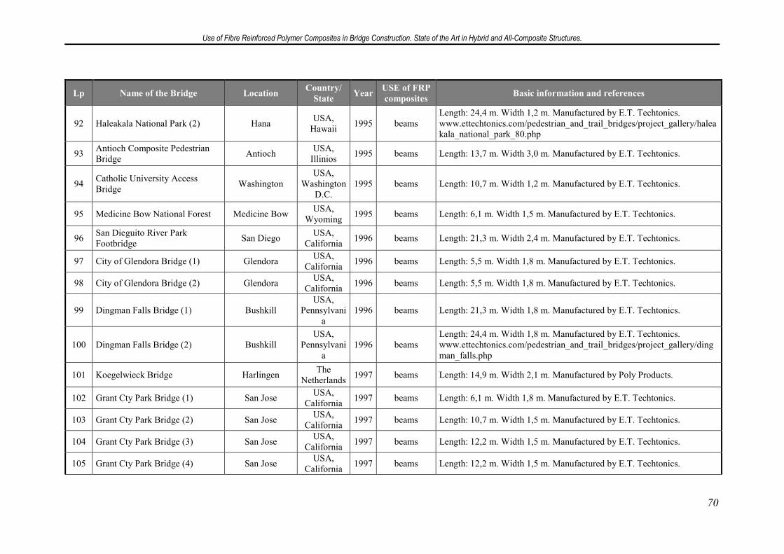
Use of Fibre Reinforced Polymer Composites in Bridge Construction. State of the Art in Hybrid and All-Composite Structures.
70
Lp Name of the Bridge Location Country/
State Year
USE of FRP
composites Basic information and references
92 Haleakala National Park (2) Hana USA,
Hawaii 1995 beams
Length: 24,4 m. Width 1,2 m. Manufactured by E.T. Techtonics. www.ettechtonics.com/pedestrian_and_trail_bridges/project_gallery/haleakala_national_park_80.php
93 Antioch Composite Pedestrian Bridge
Antioch USA,
Illinios 1995 beams Length: 13,7 m. Width 3,0 m. Manufactured by E.T. Techtonics.
94 Catholic University Access Bridge
Washington USA,
Washington D.C.
1995 beams Length: 10,7 m. Width 1,2 m. Manufactured by E.T. Techtonics.
95 Medicine Bow National Forest Medicine Bow USA,
Wyoming 1995 beams Length: 6,1 m. Width 1,5 m. Manufactured by E.T. Techtonics.
96 San Dieguito River Park Footbridge
San Diego USA,
California 1996 beams Length: 21,3 m. Width 2,4 m. Manufactured by E.T. Techtonics.
97 City of Glendora Bridge (1) Glendora USA,
California 1996 beams Length: 5,5 m. Width 1,8 m. Manufactured by E.T. Techtonics.
98 City of Glendora Bridge (2) Glendora USA,
California 1996 beams Length: 5,5 m. Width 1,8 m. Manufactured by E.T. Techtonics.
99 Dingman Falls Bridge (1) Bushkill USA,
Pennsylvania
1996 beams Length: 21,3 m. Width 1,8 m. Manufactured by E.T. Techtonics.
100 Dingman Falls Bridge (2) Bushkill USA,
Pennsylvania
1996 beams Length: 24,4 m. Width 1,8 m. Manufactured by E.T. Techtonics. www.ettechtonics.com/pedestrian_and_trail_bridges/project_gallery/dingman_falls.php
101 Koegelwieck Bridge Harlingen The
Netherlands 1997 beams Length: 14,9 m. Width 2,1 m. Manufactured by Poly Products.
102 Grant Cty Park Bridge (1) San Jose USA,
California 1997 beams Length: 6,1 m. Width 1,8 m. Manufactured by E.T. Techtonics.
103 Grant Cty Park Bridge (2) San Jose USA,
California 1997 beams Length: 10,7 m. Width 1,5 m. Manufactured by E.T. Techtonics.
104 Grant Cty Park Bridge (3) San Jose USA,
California 1997 beams Length: 12,2 m. Width 1,5 m. Manufactured by E.T. Techtonics.
105 Grant Cty Park Bridge (4) San Jose USA,
California 1997 beams Length: 12,2 m. Width 1,5 m. Manufactured by E.T. Techtonics.
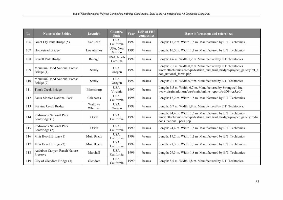
Use of Fibre Reinforced Polymer Composites in Bridge Construction. State of the Art in Hybrid and All-Composite Structures.
71
Lp Name of the Bridge Location Country/
State Year
USE of FRP
composites Basic information and references
106 Grant Cty Park Bridge (5) San Jose USA,
California 1997 beams Length: 15,2 m. Width 1,5 m. Manufactured by E.T. Techtonics.
107 Homestead Bridge Los Alamos USA, New
Mexico 1997 beams Length: 16,5 m. Width 1,2 m. Manufactured by E.T. Techtonics
108 Powell Park Bridge Raleigh USA, North
Carolina 1997 beams Length: 4,6 m. Width 1,2 m. Manufactured by E.T. Techtonics
109 Mountain Hood National Forest Bridge (1)
Sandy USA,
Oregon 1997 beams
Length: 9,1 m. Width 0,9 m. Manufactured by E.T. Techtonics www.ettechtonics.com/pedestrian_and_trail_bridges/project_gallery/mt_hood_national_forest.php
110 Mountain Hood National Forest Bridge (2)
Sandy USA,
Oregon 1997 beams Length: 9,1 m. Width 0,9 m. Manufactured by E.T. Techtonics
111 Tom's Creek Bridge Blacksburg USA,
Virginia 1997 beams
Length: 5,5 m. Width: 6,7 m. Manufactured by Strongwell Inc. www.virginiadot.org/vtrc/main/online_reports/pdf/04-cr5.pdf
112 Santa Monica National Park Calabasas USA,
California 1998 beams Length: 12,2 m. Width 1,5 m. Manufactured by E.T. Techtonics.
113 Peavine Creek Bridge Wallowa Whitman
USA, Oregon
1998 beams Length: 6,7 m. Width 1,8 m. Manufactured by E.T. Techtonics.
114 Redwoods National Park Footbridge (1)
Orick USA,
California 1999 beams
Length: 24,4 m. Width 1,5 m. Manufactured by E.T. Techtonics. www.ettechtonics.com/pedestrian_and_trail_bridges/project_gallery/redwoods_national_park.php
115 Redwoods National Park Footbridge (2)
Orick USA,
California 1999 beams Length: 24,4 m. Width 1,5 m. Manufactured by E.T. Techtonics.
116 Muir Beach Bridge (1) Muir Beach USA,
California 1999 beams Length: 15,2 m. Width 1,2 m. Manufactured by E.T. Techtonics.
117 Muir Beach Bridge (2) Muir Beach USA,
California 1999 beams Length: 21,3 m. Width 1,5 m. Manufactured by E.T. Techtonics.
118 Audubon Canyon Ranch Nature Preserve
Marshall USA,
California 1999 beams Length: 29,3 m. Width 1,8 m. Manufactured by E.T. Techtonics.
119 City of Glendora Bridge (3) Glendora USA,
California 1999 beams Length: 8,5 m. Width 1,8 m. Manufactured by E.T. Techtonics.
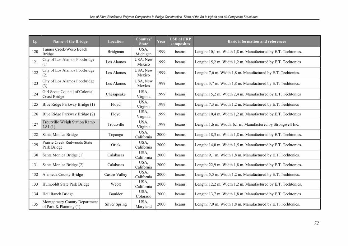
Use of Fibre Reinforced Polymer Composites in Bridge Construction. State of the Art in Hybrid and All-Composite Structures.
72
Lp Name of the Bridge Location Country/
State Year
USE of FRP
composites Basic information and references
120 Tanner Creek/Weco Beach Bridge
Bridgman USA,
Michigan 1999 beams Length: 10,1 m. Width 1,8 m. Manufactured by E.T. Techtonics.
121 City of Los Alamos Footbridge (1)
Los Alamos USA, New
Mexico 1999 beams Length: 15,2 m. Width 1,2 m. Manufactured by E.T. Techtonics
122 City of Los Alamos Footbridge (2)
Los Alamos USA, New
Mexico 1999 beams Length: 7,6 m. Width 1,8 m. Manufactured by E.T. Techtonics.
123 City of Los Alamos Footbridge (3)
Los Alamos USA, New
Mexico 1999 beams Length: 3,7 m. Width 1,8 m. Manufactured by E.T. Techtonics.
124 Girl Scout Council of Colonial Coast Bridge
Chesapeake USA,
Virginia 1999 beams Length: 15,2 m. Width 2,4 m. Manufactured by E.T. Techtonics
125 Blue Ridge Parkway Bridge (1) Floyd USA,
Virginia 1999 beams Length: 7,3 m. Width 1,2 m. Manufactured by E.T. Techtonics
126 Blue Ridge Parkway Bridge (2) Floyd USA,
Virginia 1999 beams Length: 10,4 m. Width 1,2 m. Manufactured by E.T. Techtonics
127 Troutville Weigh Station Ramp I-81 (1)
Troutville USA,
Virginia 1999 beams Length: 1,6 m. Width: 6,1 m. Manufactured by Strongwell Inc.
128 Santa Monica Bridge Topanga USA,
California 2000 beams Length: 18,3 m. Width 1,8 m. Manufactured by E.T. Techtonics.
129 Prairie Creek Redwoods State Park Bridge
Orick USA,
California 2000 beams Length: 14,0 m. Width 1,5 m. Manufactured by E.T. Techtonics.
130 Santa Monica Bridge (1) Calabasas USA,
California 2000 beams Length: 9,1 m. Width 1,8 m. Manufactured by E.T. Techtonics.
131 Santa Monica Bridge (2) Calabasas USA,
California 2000 beams Length: 22,9 m. Width 1,8 m. Manufactured by E.T. Techtonics.
132 Alameda County Bridge Castro Valley USA,
California 2000 beams Length: 5,5 m. Width 1,2 m. Manufactured by E.T. Techtonics.
133 Humboldt State Park Bridge Weott USA,
California 2000 beams Length: 12,2 m. Width 1,2 m. Manufactured by E.T. Techtonics.
134 Heil Ranch Bridge Boulder USA,
Colorado 2000 beams Length: 13,7 m. Width 1,8 m. Manufactured by E.T. Techtonics.
135 Montgomery County Department of Park & Planning (1)
Silver Spring USA,
Maryland 2000 beams Length: 7,0 m. Width 1,8 m. Manufactured by E.T. Techtonics.
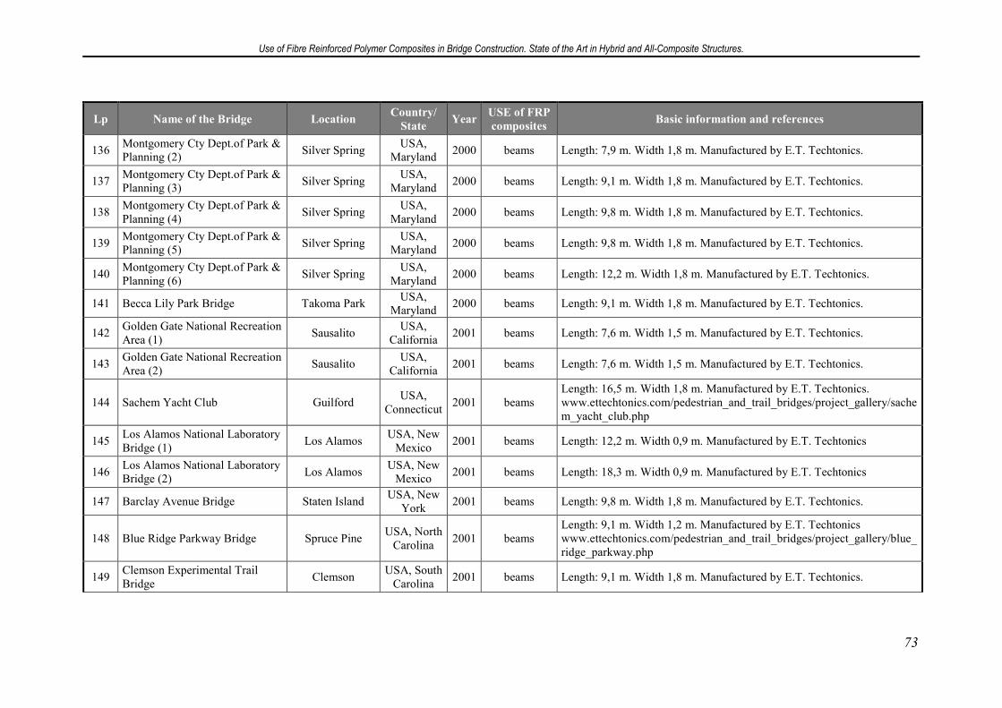
Use of Fibre Reinforced Polymer Composites in Bridge Construction. State of the Art in Hybrid and All-Composite Structures.
73
Lp Name of the Bridge Location Country/
State Year
USE of FRP
composites Basic information and references
136 Montgomery Cty Dept.of Park & Planning (2)
Silver Spring USA,
Maryland 2000 beams Length: 7,9 m. Width 1,8 m. Manufactured by E.T. Techtonics.
137 Montgomery Cty Dept.of Park & Planning (3)
Silver Spring USA,
Maryland 2000 beams Length: 9,1 m. Width 1,8 m. Manufactured by E.T. Techtonics.
138 Montgomery Cty Dept.of Park & Planning (4)
Silver Spring USA,
Maryland 2000 beams Length: 9,8 m. Width 1,8 m. Manufactured by E.T. Techtonics.
139 Montgomery Cty Dept.of Park & Planning (5)
Silver Spring USA,
Maryland 2000 beams Length: 9,8 m. Width 1,8 m. Manufactured by E.T. Techtonics.
140 Montgomery Cty Dept.of Park & Planning (6)
Silver Spring USA,
Maryland 2000 beams Length: 12,2 m. Width 1,8 m. Manufactured by E.T. Techtonics.
141 Becca Lily Park Bridge Takoma Park USA,
Maryland 2000 beams Length: 9,1 m. Width 1,8 m. Manufactured by E.T. Techtonics.
142 Golden Gate National Recreation Area (1)
Sausalito USA,
California 2001 beams Length: 7,6 m. Width 1,5 m. Manufactured by E.T. Techtonics.
143 Golden Gate National Recreation Area (2)
Sausalito USA,
California 2001 beams Length: 7,6 m. Width 1,5 m. Manufactured by E.T. Techtonics.
144 Sachem Yacht Club Guilford USA,
Connecticut 2001 beams
Length: 16,5 m. Width 1,8 m. Manufactured by E.T. Techtonics. www.ettechtonics.com/pedestrian_and_trail_bridges/project_gallery/sachem_yacht_club.php
145 Los Alamos National Laboratory Bridge (1)
Los Alamos USA, New
Mexico 2001 beams Length: 12,2 m. Width 0,9 m. Manufactured by E.T. Techtonics
146 Los Alamos National Laboratory Bridge (2)
Los Alamos USA, New
Mexico 2001 beams Length: 18,3 m. Width 0,9 m. Manufactured by E.T. Techtonics
147 Barclay Avenue Bridge Staten Island USA, New
York 2001 beams Length: 9,8 m. Width 1,8 m. Manufactured by E.T. Techtonics.
148 Blue Ridge Parkway Bridge Spruce Pine USA, North
Carolina 2001 beams
Length: 9,1 m. Width 1,2 m. Manufactured by E.T. Techtonics www.ettechtonics.com/pedestrian_and_trail_bridges/project_gallery/blue_ridge_parkway.php
149 Clemson Experimental Trail Bridge
Clemson USA, South
Carolina 2001 beams Length: 9,1 m. Width 1,8 m. Manufactured by E.T. Techtonics.
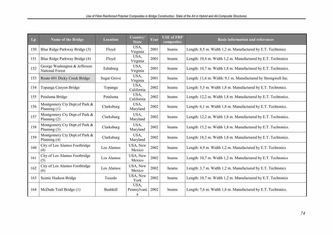
Use of Fibre Reinforced Polymer Composites in Bridge Construction. State of the Art in Hybrid and All-Composite Structures.
74
Lp Name of the Bridge Location Country/
State Year
USE of FRP
composites Basic information and references
150 Blue Ridge Parkway Bridge (3) Floyd USA,
Virginia 2001 beams Length: 8,5 m. Width 1,2 m. Manufactured by E.T. Techtonics
151 Blue Ridge Parkway Bridge (4) Floyd USA,
Virginia 2001 beams Length: 10,4 m. Width 1,2 m. Manufactured by E.T. Techtonics
152 George Washington & Jefferson National Forest
Edinburg USA,
Virginia 2001 beams Length: 10,7 m. Width 1,8 m. Manufactured by E.T. Techtonics.
153 Route 601 Dicky Creek Bridge Sugar Grove USA,
Virginia 2001 beams Length: 11,6 m. Width: 9,1 m. Manufactured by Strongwell Inc.
154 Topanga Canyon Bridge Topanga USA,
California 2002 beams Length: 5,5 m. Width 1,8 m. Manufactured by E.T. Techtonics.
155 Petaluma Bridge Petaluma USA,
California 2002 beams Length: 12,2 m. Width 1,8 m. Manufactured by E.T. Techtonics.
156 Montgomery Cty Dept.of Park & Planning (1)
Clarksburg USA,
Maryland 2002 beams Length: 6,1 m. Width 1,8 m. Manufactured by E.T. Techtonics.
157 Montgomery Cty Dept.of Park & Planning (2)
Clarksburg USA,
Maryland 2002 beams Length: 12,2 m. Width 1,8 m. Manufactured by E.T. Techtonics.
158 Montgomery Cty Dept.of Park & Planning (3)
Clarksburg USA,
Maryland 2002 beams Length: 15,2 m. Width 1,8 m. Manufactured by E.T. Techtonics.
159 Montgomery Cty Dept.of Park & Planning (4)
Clarksburg USA,
Maryland 2002 beams Length: 18,3 m. Width 1,8 m. Manufactured by E.T. Techtonics.
160 City of Los Alamos Footbridge (4)
Los Alamos USA, New
Mexico 2002 beams Length: 4,9 m. Width 1,2 m. Manufactured by E.T. Techtonics
161 City of Los Alamos Footbridge (5)
Los Alamos USA, New
Mexico 2002 beams Length: 10,7 m. Width 1,2 m. Manufactured by E.T. Techtonics
162 City of Los Alamos Footbridge (6)
Los Alamos USA, New
Mexico 2002 beams Length: 3,7 m. Width 1,2 m. Manufactured by E.T. Techtonics
163 Scenic Hudson Bridge Tuxedo USA, New
York 2002 beams Length: 10,7 m. Width 1,2 m. Manufactured by E.T. Techtonics
164 McDade Trail Bridge (1) Bushkill USA,
Pennsylvania
2002 beams Length: 7,6 m. Width 1,8 m. Manufactured by E.T. Techtonics.
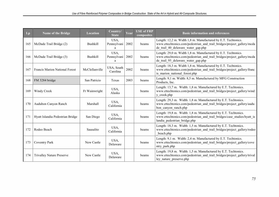
Use of Fibre Reinforced Polymer Composites in Bridge Construction. State of the Art in Hybrid and All-Composite Structures.
75
Lp Name of the Bridge Location Country/
State Year
USE of FRP
composites Basic information and references
165 McDade Trail Bridge (2) Bushkill USA,
Pennsylvania
2002 beams Length: 12,2 m. Width 1,8 m. Manufactured by E.T. Techtonics. www.ettechtonics.com/pedestrian_and_trail_bridges/project_gallery/mcdade_trail_40_delaware_water_gap.php
166 McDade Trail Bridge (3) Bushkill USA,
Pennsylvania
2002 beams Length: 29,0 m. Width 1,8 m. Manufactured by E.T. Techtonics. www.ettechtonics.com/pedestrian_and_trail_bridges/project_gallery/mcdade_trail_95_delaware_water_gap.php
167 Francis Marion National Forest McClellanville USA, South
Carolina 2002 beams
Length: 18,3 m. Width 1,8 m. Manufactured by E.T. Techtonics. www.ettechtonics.com/pedestrian_and_trail_bridges/project_gallery/francis_marion_national_forest.php
168 FM 3284 bridge San Patricio Texas 2003 beams Length: 9,1 m. Width: 8,5 m. Manufactured by MFG Construction Products, Inc.
169 Windy Creek Ft Wainwright USA,
Alaska beams
Length: 13,7 m. Width: 1,8 m. Manufactured by E.T. Techtonics. www.ettechtonics.com/pedestrian_and_trail_bridges/project_gallery/windy_creek.php
170 Audubon Canyon Ranch Marshall USA,
California beams
Length: 29,3 m. Width: 1,8 m. Manufactured by E.T. Techtonics. www.ettechtonics.com/pedestrian_and_trail_bridges/project_gallery/audubon_canyon_ranch.php
171 Hyatt Islandia Pedestrian Bridge San Diego USA,
California beams
Length: 19,8 m. Width: 1,8 m. Manufactured by E.T. Techtonics. www.ettechtonics.com/pedestrian_and_trail_bridges/case_studies/hyatt_islandia_pedestrian_bridge.php
172 Rodeo Beach Sausalito USA,
California beams
Length: 18,3 m. Width: 1,5 m. Manufactured by E.T. Techtonics. www.ettechtonics.com/pedestrian_and_trail_bridges/project_gallery/rodeo_beach.php
173 Coventry Park New Castle USA,
Delaware beams
Length: 9,1 m. Width: 2,4 m. Manufactured by E.T. Techtonics. www.ettechtonics.com/pedestrian_and_trail_bridges/project_gallery/coventry_park.php
174 Trivalley Nature Preserve New Castle USA,
Delaware beams
Length: 19,8 m. Width: 1,5 m. Manufactured by E.T. Techtonics. www.ettechtonics.com/pedestrian_and_trail_bridges/project_gallery/trivalley_nature_preserve.php
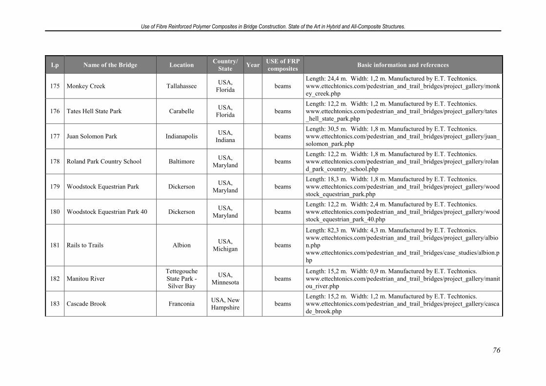
Use of Fibre Reinforced Polymer Composites in Bridge Construction. State of the Art in Hybrid and All-Composite Structures.
76
Lp Name of the Bridge Location Country/
State Year
USE of FRP
composites Basic information and references
175 Monkey Creek Tallahassee USA,
Florida beams
Length: 24,4 m. Width: 1,2 m. Manufactured by E.T. Techtonics. www.ettechtonics.com/pedestrian_and_trail_bridges/project_gallery/monkey_creek.php
176 Tates Hell State Park Carabelle USA,
Florida beams
Length: 12,2 m. Width: 1,2 m. Manufactured by E.T. Techtonics. www.ettechtonics.com/pedestrian_and_trail_bridges/project_gallery/tates_hell_state_park.php
177 Juan Solomon Park Indianapolis USA,
Indiana beams
Length: 30,5 m. Width: 1,8 m. Manufactured by E.T. Techtonics. www.ettechtonics.com/pedestrian_and_trail_bridges/project_gallery/juan_solomon_park.php
178 Roland Park Country School Baltimore USA,
Maryland beams
Length: 12,2 m. Width: 1,8 m. Manufactured by E.T. Techtonics. www.ettechtonics.com/pedestrian_and_trail_bridges/project_gallery/roland_park_country_school.php
179 Woodstock Equestrian Park Dickerson USA,
Maryland beams
Length: 18,3 m. Width: 1,8 m. Manufactured by E.T. Techtonics. www.ettechtonics.com/pedestrian_and_trail_bridges/project_gallery/woodstock_equestrian_park.php
180 Woodstock Equestrian Park 40 Dickerson USA,
Maryland beams
Length: 12,2 m. Width: 2,4 m. Manufactured by E.T. Techtonics. www.ettechtonics.com/pedestrian_and_trail_bridges/project_gallery/woodstock_equestrian_park_40.php
181 Rails to Trails Albion USA,
Michigan beams
Length: 82,3 m. Width: 4,3 m. Manufactured by E.T. Techtonics. www.ettechtonics.com/pedestrian_and_trail_bridges/project_gallery/albion.php www.ettechtonics.com/pedestrian_and_trail_bridges/case_studies/albion.php
182 Manitou River Tettegouche State Park - Silver Bay
USA, Minnesota
beams Length: 15,2 m. Width: 0,9 m. Manufactured by E.T. Techtonics. www.ettechtonics.com/pedestrian_and_trail_bridges/project_gallery/manitou_river.php
183 Cascade Brook Franconia USA, New Hampshire
beams Length: 15,2 m. Width: 1,2 m. Manufactured by E.T. Techtonics. www.ettechtonics.com/pedestrian_and_trail_bridges/project_gallery/cascade_brook.php
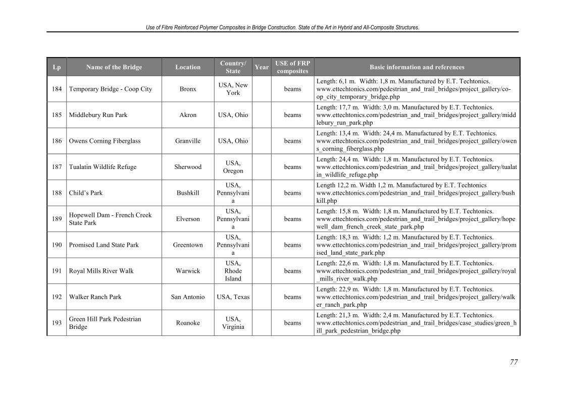
Use of Fibre Reinforced Polymer Composites in Bridge Construction. State of the Art in Hybrid and All-Composite Structures.
77
Lp Name of the Bridge Location Country/
State Year
USE of FRP
composites Basic information and references
184 Temporary Bridge - Coop City Bronx USA, New
York beams
Length: 6,1 m. Width: 1,8 m. Manufactured by E.T. Techtonics. www.ettechtonics.com/pedestrian_and_trail_bridges/project_gallery/co-op_city_temporary_bridge.php
185 Middlebury Run Park Akron USA, Ohio beams Length: 17,7 m. Width: 3,0 m. Manufactured by E.T. Techtonics. www.ettechtonics.com/pedestrian_and_trail_bridges/project_gallery/middlebury_run_park.php
186 Owens Corning Fiberglass Granville USA, Ohio beams Length: 13,4 m. Width: 24,4 m. Manufactured by E.T. Techtonics. www.ettechtonics.com/pedestrian_and_trail_bridges/project_gallery/owens_corning_fiberglass.php
187 Tualatin Wildlife Refuge Sherwood USA,
Oregon beams
Length: 24,4 m. Width: 1,8 m. Manufactured by E.T. Techtonics. www.ettechtonics.com/pedestrian_and_trail_bridges/project_gallery/tualatin_wildlife_refuge.php
188 Child’s Park Bushkill USA,
Pennsylvania
beams Length 12,2 m. Width 1,2 m. Manufactured by E.T. Techtonics www.ettechtonics.com/pedestrian_and_trail_bridges/project_gallery/bushkill.php
189 Hopewell Dam - French Creek State Park
Elverson USA,
Pennsylvania
beams Length: 15,8 m. Width: 1,8 m. Manufactured by E.T. Techtonics. www.ettechtonics.com/pedestrian_and_trail_bridges/project_gallery/hopewell_dam_french_creek_state_park.php
190 Promised Land State Park Greentown USA,
Pennsylvania
beams Length: 18,3 m. Width: 1,2 m. Manufactured by E.T. Techtonics. www.ettechtonics.com/pedestrian_and_trail_bridges/project_gallery/promised_land_state_park.php
191 Royal Mills River Walk Warwick USA, Rhode Island
beams Length: 22,6 m. Width: 1,8 m. Manufactured by E.T. Techtonics. www.ettechtonics.com/pedestrian_and_trail_bridges/project_gallery/royal_mills_river_walk.php
192 Walker Ranch Park San Antonio USA, Texas beams Length: 22,9 m. Width: 1,8 m. Manufactured by E.T. Techtonics. www.ettechtonics.com/pedestrian_and_trail_bridges/project_gallery/walker_ranch_park.php
193 Green Hill Park Pedestrian Bridge
Roanoke USA,
Virginia beams
Length: 21,3 m. Width: 2,4 m. Manufactured by E.T. Techtonics. www.ettechtonics.com/pedestrian_and_trail_bridges/case_studies/green_hill_park_pedestrian_bridge.php
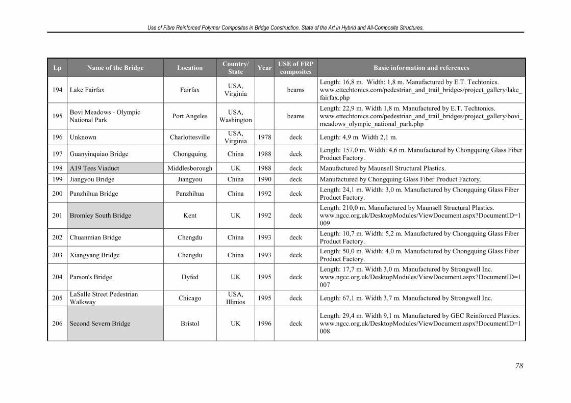
Use of Fibre Reinforced Polymer Composites in Bridge Construction. State of the Art in Hybrid and All-Composite Structures.
78
Lp Name of the Bridge Location Country/
State Year
USE of FRP
composites Basic information and references
194 Lake Fairfax Fairfax USA,
Virginia beams
Length: 16,8 m. Width: 1,8 m. Manufactured by E.T. Techtonics. www.ettechtonics.com/pedestrian_and_trail_bridges/project_gallery/lake_fairfax.php
195 Bovi Meadows - Olympic National Park
Port Angeles USA,
Washington beams
Length: 22,9 m. Width 1,8 m. Manufactured by E.T. Techtonics. www.ettechtonics.com/pedestrian_and_trail_bridges/project_gallery/bovi_meadows_olympic_national_park.php
196 Unknown Charlottesville USA,
Virginia 1978 deck Length: 4,9 m. Width 2,1 m.
197 Guanyinquiao Bridge Chongquing China 1988 deck Length: 157,0 m. Width: 4,6 m. Manufactured by Chongquing Glass Fiber Product Factory.
198 A19 Tees Viaduct Middlesborough UK 1988 deck Manufactured by Maunsell Structural Plastics.
199 Jiangyou Bridge Jiangyou China 1990 deck Manufactured by Chongquing Glass Fiber Product Factory.
200 Panzhihua Bridge Panzhihua China 1992 deck Length: 24,1 m. Width: 3,0 m. Manufactured by Chongquing Glass Fiber Product Factory.
201 Bromley South Bridge Kent UK 1992 deck Length: 210,0 m. Manufactured by Maunsell Structural Plastics. www.ngcc.org.uk/DesktopModules/ViewDocument.aspx?DocumentID=1009
202 Chuanmian Bridge Chengdu China 1993 deck Length: 10,7 m. Width: 5,2 m. Manufactured by Chongquing Glass Fiber Product Factory.
203 Xiangyang Bridge Chengdu China 1993 deck Length: 50,0 m. Width: 4,0 m. Manufactured by Chongquing Glass Fiber Product Factory.
204 Parson's Bridge Dyfed UK 1995 deck Length: 17,7 m. Width 3,0 m. Manufactured by Strongwell Inc. www.ngcc.org.uk/DesktopModules/ViewDocument.aspx?DocumentID=1007
205 LaSalle Street Pedestrian Walkway
Chicago USA,
Illinios 1995 deck Length: 67,1 m. Width 3,7 m. Manufactured by Strongwell Inc.
206 Second Severn Bridge Bristol UK 1996 deck Length: 29,4 m. Width 9,1 m. Manufactured by GEC Reinforced Plastics. www.ngcc.org.uk/DesktopModules/ViewDocument.aspx?DocumentID=1008
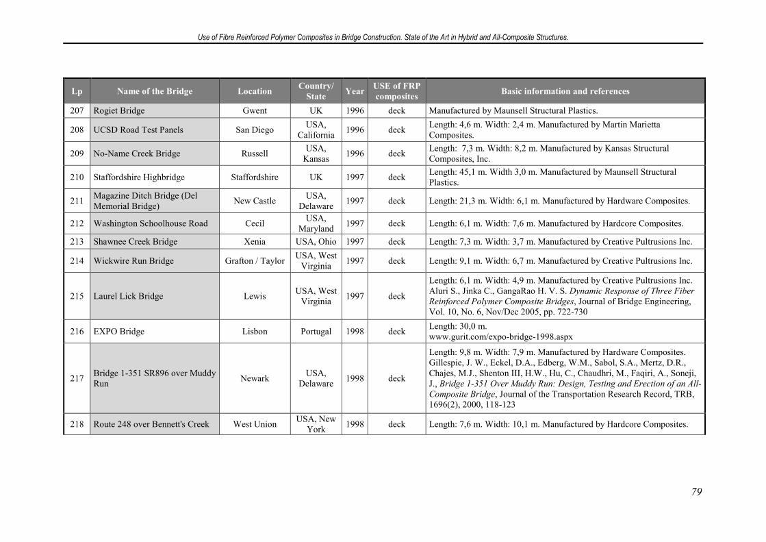
Use of Fibre Reinforced Polymer Composites in Bridge Construction. State of the Art in Hybrid and All-Composite Structures.
79
Lp Name of the Bridge Location Country/
State Year
USE of FRP
composites Basic information and references
207 Rogiet Bridge Gwent UK 1996 deck Manufactured by Maunsell Structural Plastics.
208 UCSD Road Test Panels San Diego USA,
California 1996 deck
Length: 4,6 m. Width: 2,4 m. Manufactured by Martin Marietta Composites.
209 No-Name Creek Bridge Russell USA,
Kansas 1996 deck
Length: 7,3 m. Width: 8,2 m. Manufactured by Kansas Structural Composites, Inc.
210 Staffordshire Highbridge Staffordshire UK 1997 deck Length: 45,1 m. Width 3,0 m. Manufactured by Maunsell Structural Plastics.
211 Magazine Ditch Bridge (Del Memorial Bridge)
New Castle USA,
Delaware 1997 deck Length: 21,3 m. Width: 6,1 m. Manufactured by Hardware Composites.
212 Washington Schoolhouse Road Cecil USA,
Maryland 1997 deck Length: 6,1 m. Width: 7,6 m. Manufactured by Hardcore Composites.
213 Shawnee Creek Bridge Xenia USA, Ohio 1997 deck Length: 7,3 m. Width: 3,7 m. Manufactured by Creative Pultrusions Inc.
214 Wickwire Run Bridge Grafton / Taylor USA, West
Virginia 1997 deck Length: 9,1 m. Width: 6,7 m. Manufactured by Creative Pultrusions Inc.
215 Laurel Lick Bridge Lewis USA, West
Virginia 1997 deck
Length: 6,1 m. Width: 4,9 m. Manufactured by Creative Pultrusions Inc. Aluri S., Jinka C., GangaRao H. V. S. Dynamic Response of Three Fiber
Reinforced Polymer Composite Bridges, Journal of Bridge Engineering, Vol. 10, No. 6, Nov/Dec 2005, pp. 722-730
216 EXPO Bridge Lisbon Portugal 1998 deck Length: 30,0 m. www.gurit.com/expo-bridge-1998.aspx
217 Bridge 1-351 SR896 over Muddy Run
Newark USA,
Delaware 1998 deck
Length: 9,8 m. Width: 7,9 m. Manufactured by Hardware Composites. Gillespie, J. W., Eckel, D.A., Edberg, W.M., Sabol, S.A., Mertz, D.R., Chajes, M.J., Shenton III, H.W., Hu, C., Chaudhri, M., Faqiri, A., Soneji, J., Bridge 1-351 Over Muddy Run: Design, Testing and Erection of an All-
Composite Bridge, Journal of the Transportation Research Record, TRB, 1696(2), 2000, 118-123
218 Route 248 over Bennett's Creek West Union USA, New
York 1998 deck Length: 7,6 m. Width: 10,1 m. Manufactured by Hardcore Composites.
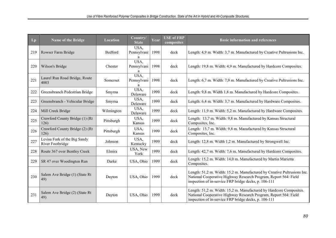
Use of Fibre Reinforced Polymer Composites in Bridge Construction. State of the Art in Hybrid and All-Composite Structures.
80
Lp Name of the Bridge Location Country/
State Year
USE of FRP
composites Basic information and references
219 Rowser Farm Bridge Bedford USA,
Pennsylvania
1998 deck Length: 4,9 m. Width: 3,7 m. Manufactured by Creative Pultrusions Inc.
220 Wilson's Bridge Chester USA,
Pennsylvania
1998 deck Length: 19,8 m. Width: 4,9 m. Manufactured by Hardcore Composites.
221 Laurel Run Road Bridge, Route 4003
Somerset USA,
Pennsylvania
1998 deck Length: 6,7 m. Width: 7,9 m. Manufactured by Creative Pultrusions Inc.
222 Greensbranch Pedestrian Bridge Smyrna USA,
Delaware 1999 deck Length: 9,8 m. Width 1,8 m. Manufactured by Hardcore Composites.
223 Greensbranch - Vehicular Bridge Smyrna USA,
Delaware 1999 deck Length: 6,4 m. Width: 3,7 m. Manufactured by Hardware Composites.
224 Mill Creek Bridge Wilmington USA,
Delaware 1999 deck Length: 11,9 m. Width: 5,2 m. Manufactured by Hardware Composites.
225 Crawford County Bridge (1) (Rt 126)
Pittsburgh USA,
Kansas 1999 deck
Length: 13,7 m. Width: 9,8 m. Manufactured by Kansas Structural Composites, Inc.
226 Crawford County Bridge (2) (Rt 126)
Pittsburgh USA,
Kansas 1999 deck
Length: 13,7 m. Width: 9,8 m. Manufactured by Kansas Structural Composites, Inc.
227 Levisa Fork of the Big Sandy River Footbridge
Johnson USA,
Kentucky 1999 deck Length: 12,8 m. Width 1,2 m. Manufactured by Strongwell Inc.
228 Route 367 over Bentley Creek Elmira USA, New
York 1999 deck Length: 42,7 m. Width: 7,6 m. Manufactured by Hardcore Composites.
229 SR 47 over Woodington Run Darke USA, Ohio 1999 deck Length: 15,2 m. Width: 14,0 m. Manufactured by Martin Marietta Composites.
230 Salem Ave Bridge (1) (State Rt 49)
Dayton USA, Ohio 1999 deck Length: 51,2 m. Width: 15,2 m. Manufactured by Creative Pultrusions Inc. National Cooperative Highway Research Program, Report 564: Field inspection of in-service FRP bridge decks, p. 106-111
231 Salem Ave Bridge (2) (State Rt 49)
Dayton USA, Ohio 1999 deck Length: 51,2 m. Width: 15,2 m. Manufactured by Hardcore Composites. National Cooperative Highway Research Program, Report 564: Field inspection of in-service FRP bridge decks, p. 106-111
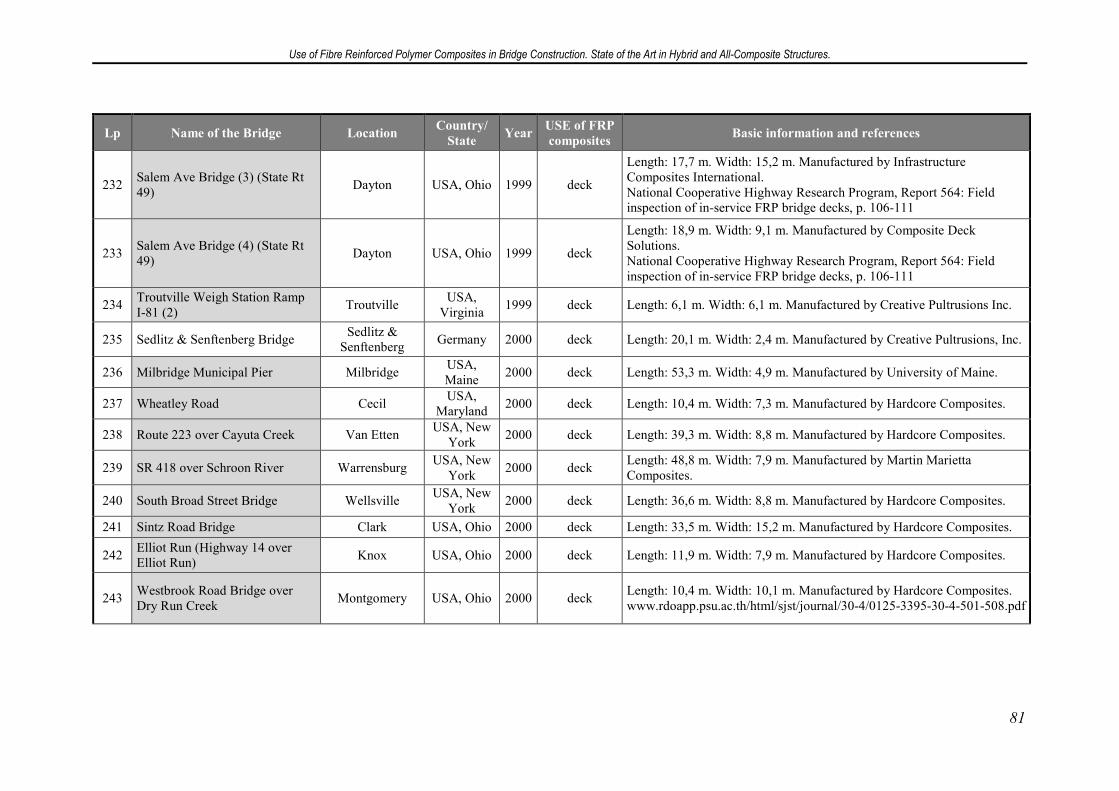
Use of Fibre Reinforced Polymer Composites in Bridge Construction. State of the Art in Hybrid and All-Composite Structures.
81
Lp Name of the Bridge Location Country/
State Year
USE of FRP
composites Basic information and references
232 Salem Ave Bridge (3) (State Rt 49)
Dayton USA, Ohio 1999 deck
Length: 17,7 m. Width: 15,2 m. Manufactured by Infrastructure Composites International. National Cooperative Highway Research Program, Report 564: Field inspection of in-service FRP bridge decks, p. 106-111
233 Salem Ave Bridge (4) (State Rt 49)
Dayton USA, Ohio 1999 deck
Length: 18,9 m. Width: 9,1 m. Manufactured by Composite Deck Solutions. National Cooperative Highway Research Program, Report 564: Field inspection of in-service FRP bridge decks, p. 106-111
234 Troutville Weigh Station Ramp I-81 (2)
Troutville USA,
Virginia 1999 deck Length: 6,1 m. Width: 6,1 m. Manufactured by Creative Pultrusions Inc.
235 Sedlitz & Senftenberg Bridge Sedlitz &
Senftenberg Germany 2000 deck Length: 20,1 m. Width: 2,4 m. Manufactured by Creative Pultrusions, Inc.
236 Milbridge Municipal Pier Milbridge USA, Maine
2000 deck Length: 53,3 m. Width: 4,9 m. Manufactured by University of Maine.
237 Wheatley Road Cecil USA,
Maryland 2000 deck Length: 10,4 m. Width: 7,3 m. Manufactured by Hardcore Composites.
238 Route 223 over Cayuta Creek Van Etten USA, New
York 2000 deck Length: 39,3 m. Width: 8,8 m. Manufactured by Hardcore Composites.
239 SR 418 over Schroon River Warrensburg USA, New
York 2000 deck
Length: 48,8 m. Width: 7,9 m. Manufactured by Martin Marietta Composites.
240 South Broad Street Bridge Wellsville USA, New
York 2000 deck Length: 36,6 m. Width: 8,8 m. Manufactured by Hardcore Composites.
241 Sintz Road Bridge Clark USA, Ohio 2000 deck Length: 33,5 m. Width: 15,2 m. Manufactured by Hardcore Composites.
242 Elliot Run (Highway 14 over Elliot Run)
Knox USA, Ohio 2000 deck Length: 11,9 m. Width: 7,9 m. Manufactured by Hardcore Composites.
243 Westbrook Road Bridge over Dry Run Creek
Montgomery USA, Ohio 2000 deck Length: 10,4 m. Width: 10,1 m. Manufactured by Hardcore Composites. www.rdoapp.psu.ac.th/html/sjst/journal/30-4/0125-3395-30-4-501-508.pdf
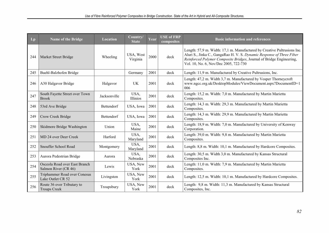
Use of Fibre Reinforced Polymer Composites in Bridge Construction. State of the Art in Hybrid and All-Composite Structures.
82
Lp Name of the Bridge Location Country/
State Year
USE of FRP
composites Basic information and references
244 Market Street Bridge Wheeling USA, West
Virginia 2000 deck
Length: 57,9 m. Width: 17,1 m. Manufactured by Creative Pultrusions Inc. Aluri S., Jinka C., GangaRao H. V. S. Dynamic Response of Three Fiber
Reinforced Polymer Composite Bridges, Journal of Bridge Engineering, Vol. 10, No. 6, Nov/Dec 2005, 722-730
245 Buehl-Balzhofen Bridge Germany 2001 deck Length: 11,9 m. Manufactured by Creative Pultrusions, Inc.
246 A30 Halgavor Bridge Halgavor UK 2001 deck Length: 47,2 m. Width 3,7 m. Manufactured by Vosper Thorneycroft www.ngcc.org.uk/DesktopModules/ViewDocument.aspx?DocumentID=1006
247 South Fayette Street over Town Brook
Jacksonville USA,
Illinios 2001 deck
Length: 15,2 m. Width: 7,0 m. Manufactured by Martin Marietta Composites.
248 53rd Ave Bridge Bettendorf USA, Iowa 2001 deck Length: 14,3 m. Width: 29,3 m. Manufactured by Martin Marietta Composites.
249 Crow Creek Bridge Bettendorf USA, Iowa 2001 deck Length: 14,3 m. Width: 29,9 m. Manufactured by Martin Marietta Composites.
250 Skidmore Bridge Washington Union USA, Maine
2001 deck Length: 18,9 m. Width: 7,0 m. Manufactured by University of Kenway Corporation.
251 MD 24 over Deer Creek Harford USA,
Maryland 2001 deck
Length: 39,0 m. Width: 9,8 m. Manufactured by Martin Marietta Composites.
252 Snouffer School Road Montgomery USA,
Maryland 2001 deck Length: 8,8 m. Width: 10,1 m. Manufactured by Hardcore Composites.
253 Aurora Pedestrian Bridge Aurora USA,
Nebraska 2001 deck
Length: 30,5 m. Width 3,0 m. Manufactured by Kansas Structural Composites Inc.
254 Osceola Road over East Branch Salmon River (CR 46)
Lewis USA, New
York 2001 deck
Length: 11,0 m. Width: 7,9 m. Manufactured by Martin Marietta Composites.
255 Triphammer Road over Conesus Lake Outlet CR 52
Livingston USA, New
York 2001 deck Length: 12,5 m. Width: 10,1 m. Manufactured by Hardcore Composites.
256 Route 36 over Tributary to Troups Creek
Troupsbury USA, New
York 2001 deck
Length: 9,8 m. Width: 11,3 m. Manufactured by Kansas Structural Composites, Inc.
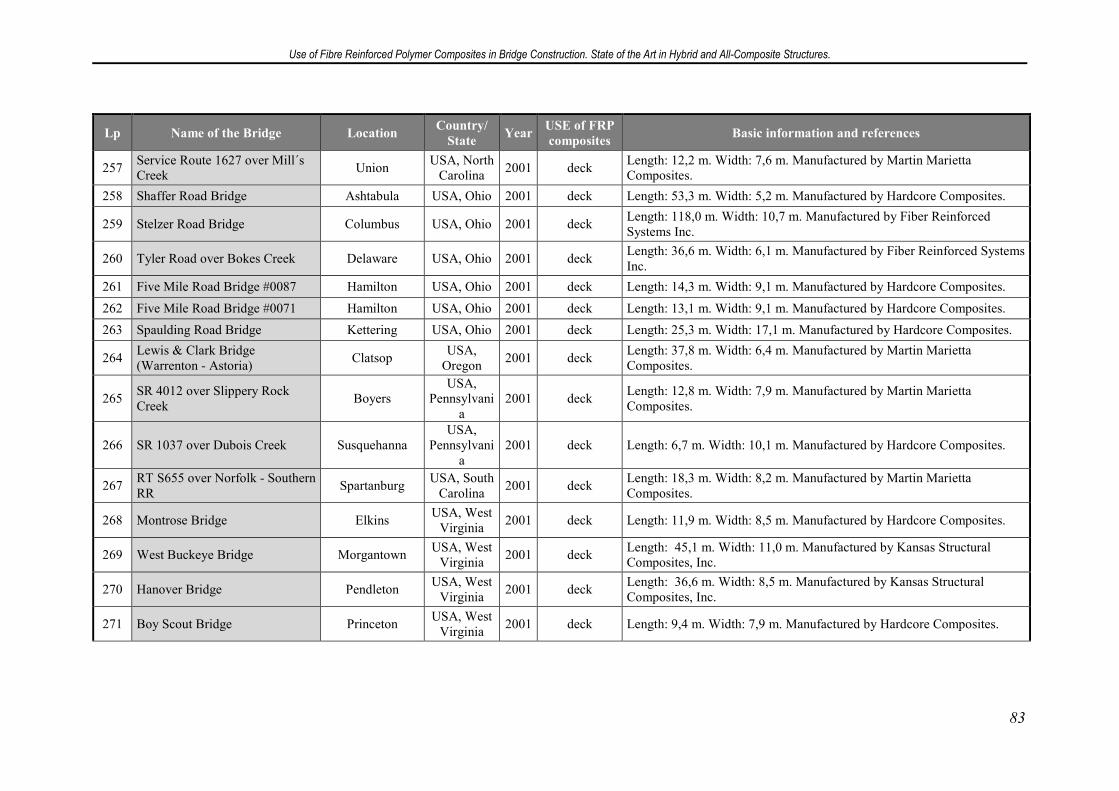
Use of Fibre Reinforced Polymer Composites in Bridge Construction. State of the Art in Hybrid and All-Composite Structures.
83
Lp Name of the Bridge Location Country/
State Year
USE of FRP
composites Basic information and references
257 Service Route 1627 over Mill´s Creek
Union USA, North
Carolina 2001 deck
Length: 12,2 m. Width: 7,6 m. Manufactured by Martin Marietta Composites.
258 Shaffer Road Bridge Ashtabula USA, Ohio 2001 deck Length: 53,3 m. Width: 5,2 m. Manufactured by Hardcore Composites.
259 Stelzer Road Bridge Columbus USA, Ohio 2001 deck Length: 118,0 m. Width: 10,7 m. Manufactured by Fiber Reinforced Systems Inc.
260 Tyler Road over Bokes Creek Delaware USA, Ohio 2001 deck Length: 36,6 m. Width: 6,1 m. Manufactured by Fiber Reinforced Systems Inc.
261 Five Mile Road Bridge #0087 Hamilton USA, Ohio 2001 deck Length: 14,3 m. Width: 9,1 m. Manufactured by Hardcore Composites.
262 Five Mile Road Bridge #0071 Hamilton USA, Ohio 2001 deck Length: 13,1 m. Width: 9,1 m. Manufactured by Hardcore Composites.
263 Spaulding Road Bridge Kettering USA, Ohio 2001 deck Length: 25,3 m. Width: 17,1 m. Manufactured by Hardcore Composites.
264 Lewis & Clark Bridge (Warrenton - Astoria)
Clatsop USA,
Oregon 2001 deck
Length: 37,8 m. Width: 6,4 m. Manufactured by Martin Marietta Composites.
265 SR 4012 over Slippery Rock Creek
Boyers USA,
Pennsylvania
2001 deck Length: 12,8 m. Width: 7,9 m. Manufactured by Martin Marietta Composites.
266 SR 1037 over Dubois Creek Susquehanna USA,
Pennsylvania
2001 deck Length: 6,7 m. Width: 10,1 m. Manufactured by Hardcore Composites.
267 RT S655 over Norfolk - Southern RR
Spartanburg USA, South
Carolina 2001 deck
Length: 18,3 m. Width: 8,2 m. Manufactured by Martin Marietta Composites.
268 Montrose Bridge Elkins USA, West
Virginia 2001 deck Length: 11,9 m. Width: 8,5 m. Manufactured by Hardcore Composites.
269 West Buckeye Bridge Morgantown USA, West
Virginia 2001 deck
Length: 45,1 m. Width: 11,0 m. Manufactured by Kansas Structural Composites, Inc.
270 Hanover Bridge Pendleton USA, West
Virginia 2001 deck
Length: 36,6 m. Width: 8,5 m. Manufactured by Kansas Structural Composites, Inc.
271 Boy Scout Bridge Princeton USA, West
Virginia 2001 deck Length: 9,4 m. Width: 7,9 m. Manufactured by Hardcore Composites.
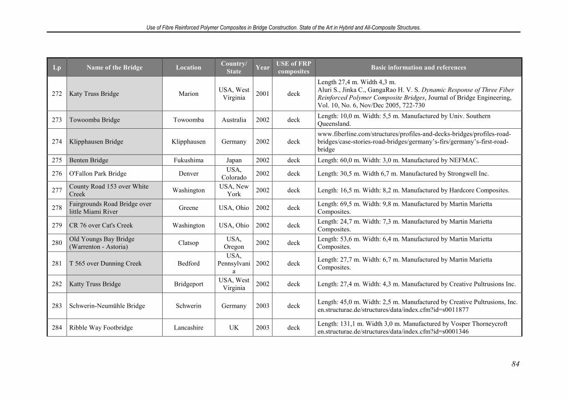
Use of Fibre Reinforced Polymer Composites in Bridge Construction. State of the Art in Hybrid and All-Composite Structures.
84
Lp Name of the Bridge Location Country/
State Year
USE of FRP
composites Basic information and references
272 Katy Truss Bridge Marion USA, West
Virginia 2001 deck
Length 27,4 m. Width 4,3 m. Aluri S., Jinka C., GangaRao H. V. S. Dynamic Response of Three Fiber
Reinforced Polymer Composite Bridges, Journal of Bridge Engineering, Vol. 10, No. 6, Nov/Dec 2005, 722-730
273 Towoomba Bridge Towoomba Australia 2002 deck Length: 10,0 m. Width: 5,5 m. Manufactured by Univ. Southern Queensland.
274 Klipphausen Bridge Klipphausen Germany 2002 deck www.fiberline.com/structures/profiles-and-decks-bridges/profiles-road-bridges/case-stories-road-bridges/germany’s-firs/germany’s-first-road-bridge
275 Benten Bridge Fukushima Japan 2002 deck Length: 60,0 m. Width: 3,0 m. Manufactured by NEFMAC.
276 O'Fallon Park Bridge Denver USA,
Colorado 2002 deck Length: 30,5 m. Width 6,7 m. Manufactured by Strongwell Inc.
277 County Road 153 over White Creek
Washington USA, New
York 2002 deck Length: 16,5 m. Width: 8,2 m. Manufactured by Hardcore Composites.
278 Fairgrounds Road Bridge over little Miami River
Greene USA, Ohio 2002 deck Length: 69,5 m. Width: 9,8 m. Manufactured by Martin Marietta Composites.
279 CR 76 over Cat's Creek Washington USA, Ohio 2002 deck Length: 24,7 m. Width: 7,3 m. Manufactured by Martin Marietta Composites.
280 Old Youngs Bay Bridge (Warrenton - Astoria)
Clatsop USA,
Oregon 2002 deck
Length: 53,6 m. Width: 6,4 m. Manufactured by Martin Marietta Composites.
281 T 565 over Dunning Creek Bedford USA,
Pennsylvania
2002 deck Length: 27,7 m. Width: 6,7 m. Manufactured by Martin Marietta Composites.
282 Katty Truss Bridge Bridgeport USA, West
Virginia 2002 deck Length: 27,4 m. Width: 4,3 m. Manufactured by Creative Pultrusions Inc.
283 Schwerin-Neumühle Bridge Schwerin Germany 2003 deck Length: 45,0 m. Width: 2,5 m. Manufactured by Creative Pultrusions, Inc. en.structurae.de/structures/data/index.cfm?id=s0011877
284 Ribble Way Footbridge Lancashire UK 2003 deck Length: 131,1 m. Width 3,0 m. Manufactured by Vosper Thorneycroft en.structurae.de/structures/data/index.cfm?id=s0001346
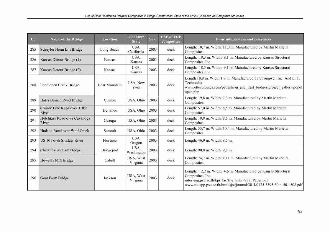
Use of Fibre Reinforced Polymer Composites in Bridge Construction. State of the Art in Hybrid and All-Composite Structures.
85
Lp Name of the Bridge Location Country/
State Year
USE of FRP
composites Basic information and references
285 Schuyler Heim Lift Bridge Long Beach USA,
California 2003 deck
Length: 10,7 m. Width: 11,0 m. Manufactured by Martin Marietta Composites.
286 Kansas Detour Bridge (1) Kansas USA,
Kansas 2003 deck
Length: 18,3 m. Width: 9,1 m. Manufactured by Kansas Structural Composites, Inc.
287 Kansas Detour Bridge (2) Kansas USA,
Kansas 2003 deck
Length: 18,3 m. Width: 9,1 m. Manufactured by Kansas Structural Composites, Inc.
288 Popolopen Creek Bridge Bear Mountain USA, New
York 2003 deck
Length 18,9 m. Width 1,8 m. Manufactured by Strongwell Inc. And E. T. Techtonics www.ettechtonics.com/pedestrian_and_trail_bridges/project_gallery/popolopen.php
289 Hales Branch Road Bridge Clinton USA, Ohio 2003 deck Length: 19,8 m. Width: 7,3 m. Manufactured by Martin Marietta Composites.
290 County Line Road over Tiffin River
Defiance USA, Ohio 2003 deck Length: 57,0 m. Width: 8,5 m. Manufactured by Martin Marietta Composites.
291 Hotchkiss Road over Cuyahoga River
Geauga USA, Ohio 2003 deck Length: 19,8 m. Width: 8,5 m. Manufactured by Martin Marietta Composites.
292 Hudson Road over Wolf Creek Summit USA, Ohio 2003 deck Length: 35,7 m. Width: 10,4 m. Manufactured by Martin Marietta Composites.
293 US 101 over Siuslaw River Florence USA,
Oregon 2003 deck Length: 46,9 m. Width: 8,5 m.
294 Chief Joseph Dam Bridge Bridgeport USA,
Washington 2003 deck Length: 90,8 m. Width: 9,8 m.
295 Howell's Mill Bridge Cabell USA, West
Virginia 2003 deck
Length: 74,7 m. Width: 10,1 m. Manufactured by Martin Marietta Composites.
296 Goat Farm Bridge Jackson USA, West
Virginia 2003 deck
Length: 12,2 m. Width: 4,6 m. Manufactured by Kansas Structural Composites, Inc. infor.eng.psu.ac.th/kpi_fac/file_link/P937FPaper.pdf www.rdoapp.psu.ac.th/html/sjst/journal/30-4/0125-3395-30-4-501-508.pdf
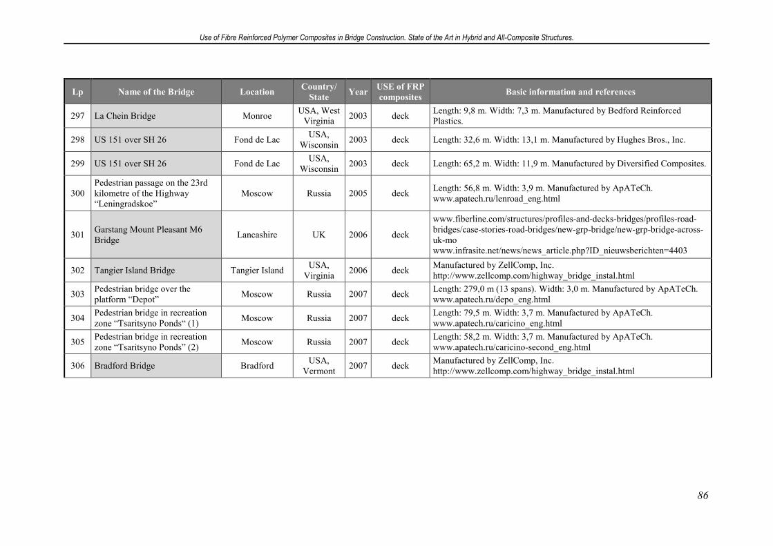
Use of Fibre Reinforced Polymer Composites in Bridge Construction. State of the Art in Hybrid and All-Composite Structures.
86
Lp Name of the Bridge Location Country/
State Year
USE of FRP
composites Basic information and references
297 La Chein Bridge Monroe USA, West
Virginia 2003 deck
Length: 9,8 m. Width: 7,3 m. Manufactured by Bedford Reinforced Plastics.
298 US 151 over SH 26 Fond de Lac USA,
Wisconsin 2003 deck Length: 32,6 m. Width: 13,1 m. Manufactured by Hughes Bros., Inc.
299 US 151 over SH 26 Fond de Lac USA,
Wisconsin 2003 deck Length: 65,2 m. Width: 11,9 m. Manufactured by Diversified Composites.
300 Pedestrian passage on the 23rd kilometre of the Highway “Leningradskoe”
Moscow Russia 2005 deck Length: 56,8 m. Width: 3,9 m. Manufactured by ApATeCh. www.apatech.ru/lenroad_eng.html
301 Garstang Mount Pleasant M6 Bridge
Lancashire UK 2006 deck
www.fiberline.com/structures/profiles-and-decks-bridges/profiles-road-bridges/case-stories-road-bridges/new-grp-bridge/new-grp-bridge-across-uk-mo www.infrasite.net/news/news_article.php?ID_nieuwsberichten=4403
302 Tangier Island Bridge Tangier Island USA,
Virginia 2006 deck
Manufactured by ZellComp, Inc. http://www.zellcomp.com/highway_bridge_instal.html
303 Pedestrian bridge over the platform “Depot”
Moscow Russia 2007 deck Length: 279,0 m (13 spans). Width: 3,0 m. Manufactured by ApATeCh. www.apatech.ru/depo_eng.html
304 Pedestrian bridge in recreation zone “Tsaritsyno Ponds“ (1)
Moscow Russia 2007 deck Length: 79,5 m. Width: 3,7 m. Manufactured by ApATeCh. www.apatech.ru/caricino_eng.html
305 Pedestrian bridge in recreation zone “Tsaritsyno Ponds” (2)
Moscow Russia 2007 deck Length: 58,2 m. Width: 3,7 m. Manufactured by ApATeCh. www.apatech.ru/caricino-second_eng.html
306 Bradford Bridge Bradford USA,
Vermont 2007 deck
Manufactured by ZellComp, Inc. http://www.zellcomp.com/highway_bridge_instal.html
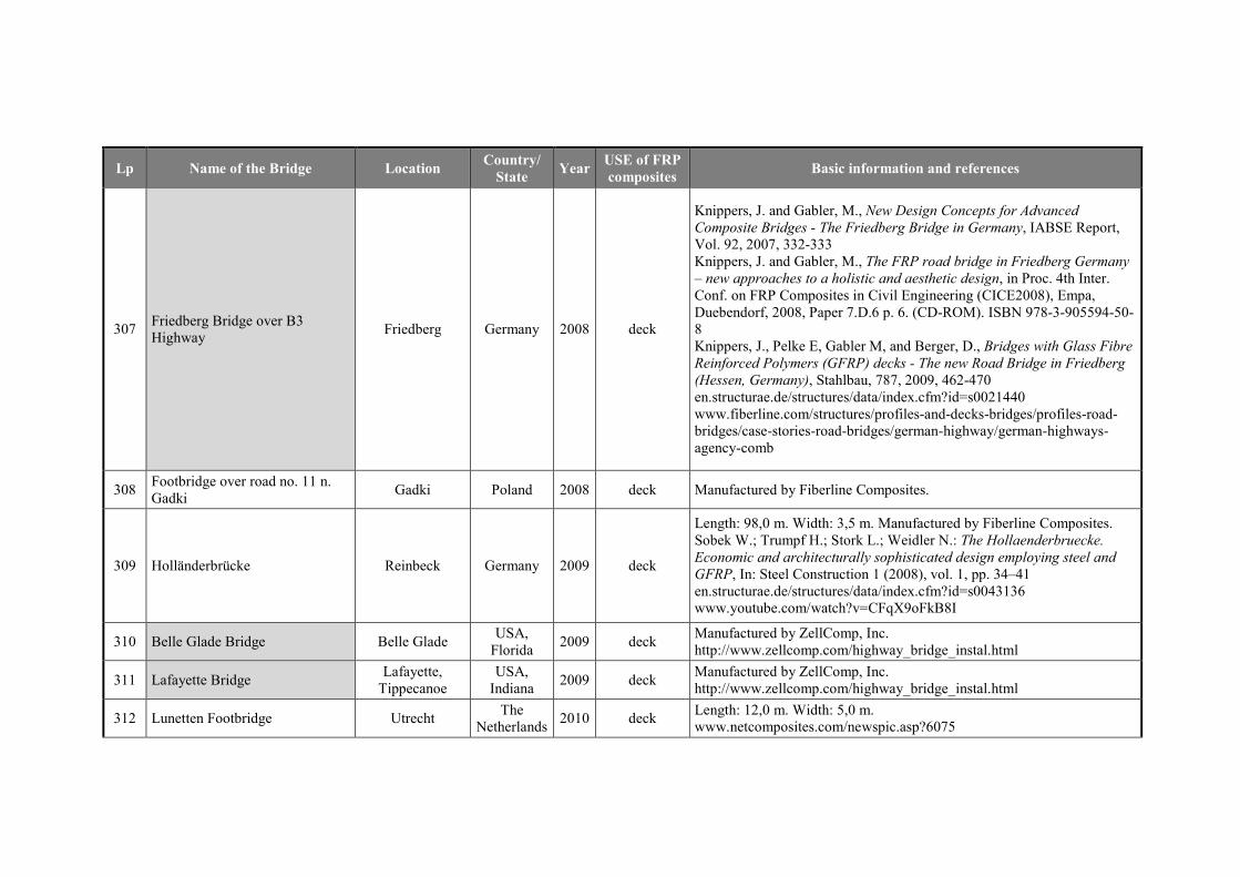
Lp Name of the Bridge Location Country/
State Year
USE of FRP
composites Basic information and references
307 Friedberg Bridge over B3 Highway
Friedberg Germany 2008 deck
Knippers, J. and Gabler, M., New Design Concepts for Advanced
Composite Bridges - The Friedberg Bridge in Germany, IABSE Report, Vol. 92, 2007, 332-333 Knippers, J. and Gabler, M., The FRP road bridge in Friedberg Germany
– new approaches to a holistic and aesthetic design, in Proc. 4th Inter. Conf. on FRP Composites in Civil Engineering (CICE2008), Empa, Duebendorf, 2008, Paper 7.D.6 p. 6. (CD-ROM). ISBN 978-3-905594-50-8 Knippers, J., Pelke E, Gabler M, and Berger, D., Bridges with Glass Fibre
Reinforced Polymers (GFRP) decks - The new Road Bridge in Friedberg
(Hessen, Germany), Stahlbau, 787, 2009, 462-470 en.structurae.de/structures/data/index.cfm?id=s0021440 www.fiberline.com/structures/profiles-and-decks-bridges/profiles-road-bridges/case-stories-road-bridges/german-highway/german-highways-agency-comb
308 Footbridge over road no. 11 n. Gadki
Gadki Poland 2008 deck Manufactured by Fiberline Composites.
309 Holländerbrücke Reinbeck Germany 2009 deck
Length: 98,0 m. Width: 3,5 m. Manufactured by Fiberline Composites. Sobek W.; Trumpf H.; Stork L.; Weidler N.: The Hollaenderbruecke.
Economic and architecturally sophisticated design employing steel and
GFRP, In: Steel Construction 1 (2008), vol. 1, pp. 34–41 en.structurae.de/structures/data/index.cfm?id=s0043136 www.youtube.com/watch?v=CFqX9oFkB8I
310 Belle Glade Bridge Belle Glade USA,
Florida 2009 deck
Manufactured by ZellComp, Inc. http://www.zellcomp.com/highway_bridge_instal.html
311 Lafayette Bridge Lafayette,
Tippecanoe USA,
Indiana 2009 deck
Manufactured by ZellComp, Inc. http://www.zellcomp.com/highway_bridge_instal.html
312 Lunetten Footbridge Utrecht The
Netherlands 2010 deck
Length: 12,0 m. Width: 5,0 m. www.netcomposites.com/newspic.asp?6075
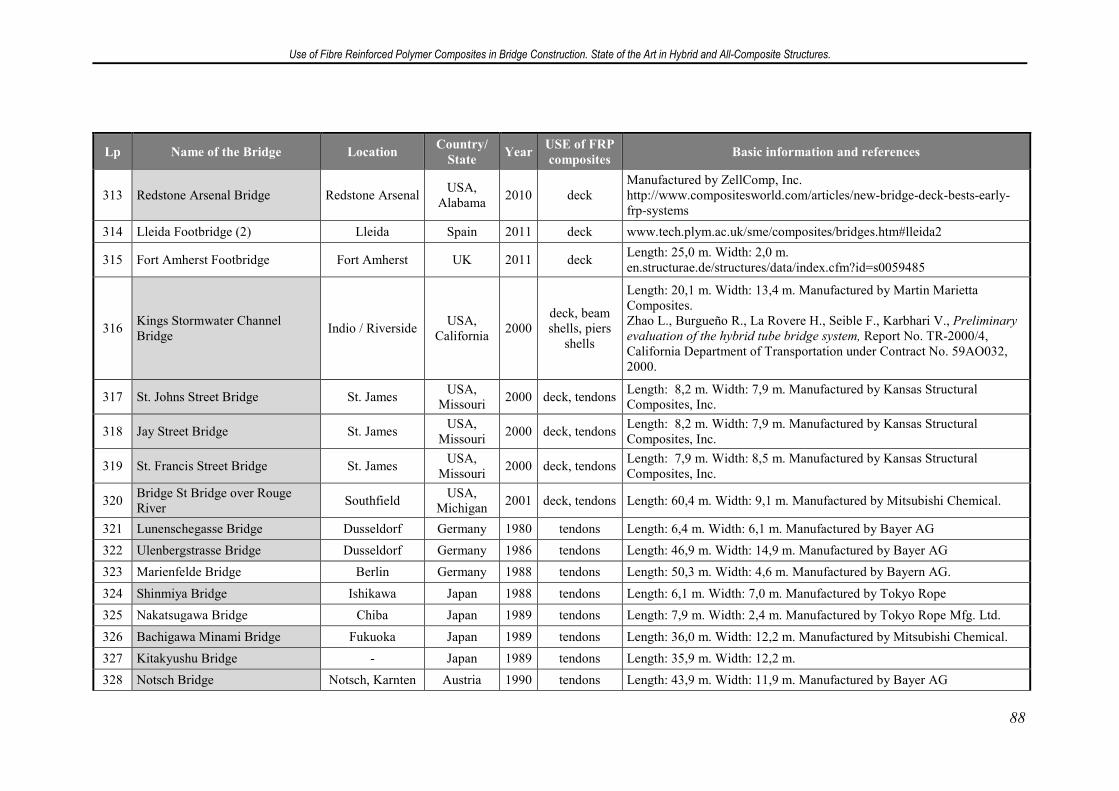
Use of Fibre Reinforced Polymer Composites in Bridge Construction. State of the Art in Hybrid and All-Composite Structures.
88
Lp Name of the Bridge Location Country/
State Year
USE of FRP
composites Basic information and references
313 Redstone Arsenal Bridge Redstone Arsenal USA,
Alabama 2010 deck
Manufactured by ZellComp, Inc. http://www.compositesworld.com/articles/new-bridge-deck-bests-early-frp-systems
314 Lleida Footbridge (2) Lleida Spain 2011 deck www.tech.plym.ac.uk/sme/composites/bridges.htm#lleida2
315 Fort Amherst Footbridge Fort Amherst UK 2011 deck Length: 25,0 m. Width: 2,0 m. en.structurae.de/structures/data/index.cfm?id=s0059485
316 Kings Stormwater Channel Bridge
Indio / Riverside USA,
California 2000
deck, beam shells, piers
shells
Length: 20,1 m. Width: 13,4 m. Manufactured by Martin Marietta Composites. Zhao L., Burgueño R., La Rovere H., Seible F., Karbhari V., Preliminary
evaluation of the hybrid tube bridge system, Report No. TR-2000/4, California Department of Transportation under Contract No. 59AO032, 2000.
317 St. Johns Street Bridge St. James USA,
Missouri 2000 deck, tendons
Length: 8,2 m. Width: 7,9 m. Manufactured by Kansas Structural Composites, Inc.
318 Jay Street Bridge St. James USA,
Missouri 2000 deck, tendons
Length: 8,2 m. Width: 7,9 m. Manufactured by Kansas Structural Composites, Inc.
319 St. Francis Street Bridge St. James USA,
Missouri 2000 deck, tendons
Length: 7,9 m. Width: 8,5 m. Manufactured by Kansas Structural Composites, Inc.
320 Bridge St Bridge over Rouge River
Southfield USA,
Michigan 2001 deck, tendons Length: 60,4 m. Width: 9,1 m. Manufactured by Mitsubishi Chemical.
321 Lunenschegasse Bridge Dusseldorf Germany 1980 tendons Length: 6,4 m. Width: 6,1 m. Manufactured by Bayer AG
322 Ulenbergstrasse Bridge Dusseldorf Germany 1986 tendons Length: 46,9 m. Width: 14,9 m. Manufactured by Bayer AG
323 Marienfelde Bridge Berlin Germany 1988 tendons Length: 50,3 m. Width: 4,6 m. Manufactured by Bayern AG.
324 Shinmiya Bridge Ishikawa Japan 1988 tendons Length: 6,1 m. Width: 7,0 m. Manufactured by Tokyo Rope
325 Nakatsugawa Bridge Chiba Japan 1989 tendons Length: 7,9 m. Width: 2,4 m. Manufactured by Tokyo Rope Mfg. Ltd.
326 Bachigawa Minami Bridge Fukuoka Japan 1989 tendons Length: 36,0 m. Width: 12,2 m. Manufactured by Mitsubishi Chemical.
327 Kitakyushu Bridge - Japan 1989 tendons Length: 35,9 m. Width: 12,2 m.
328 Notsch Bridge Notsch, Karnten Austria 1990 tendons Length: 43,9 m. Width: 11,9 m. Manufactured by Bayer AG
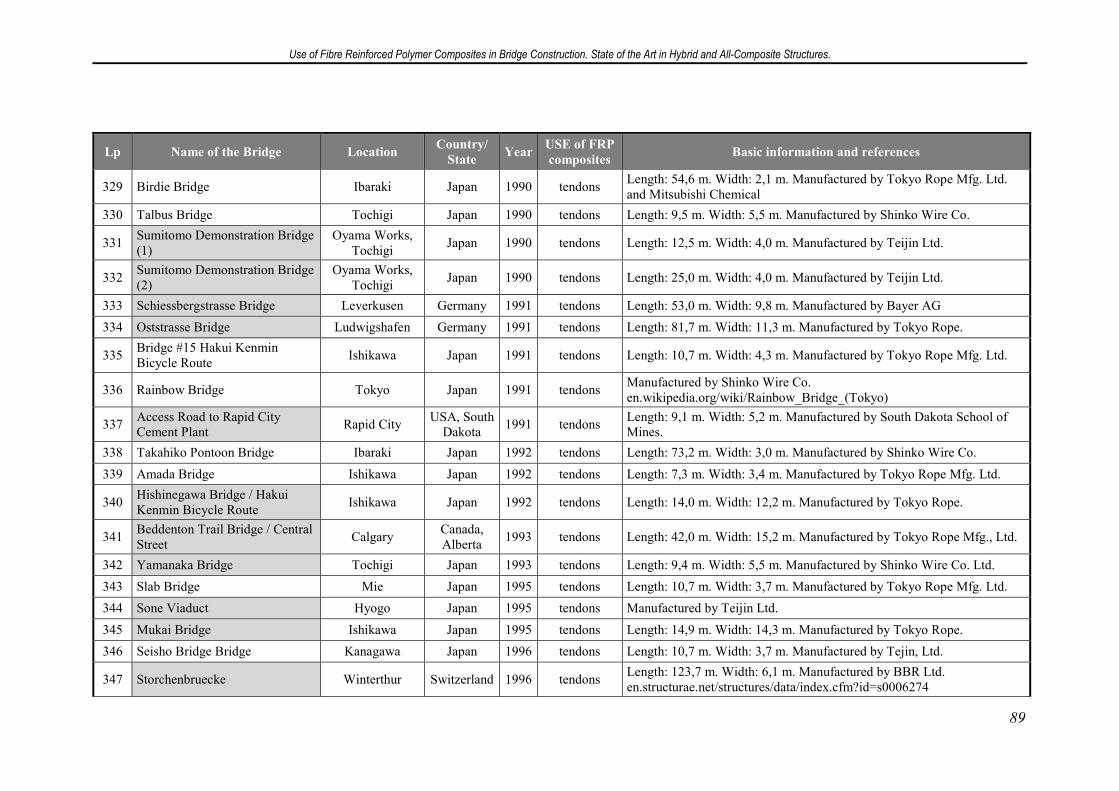
Use of Fibre Reinforced Polymer Composites in Bridge Construction. State of the Art in Hybrid and All-Composite Structures.
89
Lp Name of the Bridge Location Country/
State Year
USE of FRP
composites Basic information and references
329 Birdie Bridge Ibaraki Japan 1990 tendons Length: 54,6 m. Width: 2,1 m. Manufactured by Tokyo Rope Mfg. Ltd. and Mitsubishi Chemical
330 Talbus Bridge Tochigi Japan 1990 tendons Length: 9,5 m. Width: 5,5 m. Manufactured by Shinko Wire Co.
331 Sumitomo Demonstration Bridge (1)
Oyama Works, Tochigi
Japan 1990 tendons Length: 12,5 m. Width: 4,0 m. Manufactured by Teijin Ltd.
332 Sumitomo Demonstration Bridge (2)
Oyama Works, Tochigi
Japan 1990 tendons Length: 25,0 m. Width: 4,0 m. Manufactured by Teijin Ltd.
333 Schiessbergstrasse Bridge Leverkusen Germany 1991 tendons Length: 53,0 m. Width: 9,8 m. Manufactured by Bayer AG
334 Oststrasse Bridge Ludwigshafen Germany 1991 tendons Length: 81,7 m. Width: 11,3 m. Manufactured by Tokyo Rope.
335 Bridge #15 Hakui Kenmin Bicycle Route
Ishikawa Japan 1991 tendons Length: 10,7 m. Width: 4,3 m. Manufactured by Tokyo Rope Mfg. Ltd.
336 Rainbow Bridge Tokyo Japan 1991 tendons Manufactured by Shinko Wire Co. en.wikipedia.org/wiki/Rainbow_Bridge_(Tokyo)
337 Access Road to Rapid City Cement Plant
Rapid City USA, South
Dakota 1991 tendons
Length: 9,1 m. Width: 5,2 m. Manufactured by South Dakota School of Mines.
338 Takahiko Pontoon Bridge Ibaraki Japan 1992 tendons Length: 73,2 m. Width: 3,0 m. Manufactured by Shinko Wire Co.
339 Amada Bridge Ishikawa Japan 1992 tendons Length: 7,3 m. Width: 3,4 m. Manufactured by Tokyo Rope Mfg. Ltd.
340 Hishinegawa Bridge / Hakui Kenmin Bicycle Route
Ishikawa Japan 1992 tendons Length: 14,0 m. Width: 12,2 m. Manufactured by Tokyo Rope.
341 Beddenton Trail Bridge / Central Street
Calgary Canada, Alberta
1993 tendons Length: 42,0 m. Width: 15,2 m. Manufactured by Tokyo Rope Mfg., Ltd.
342 Yamanaka Bridge Tochigi Japan 1993 tendons Length: 9,4 m. Width: 5,5 m. Manufactured by Shinko Wire Co. Ltd.
343 Slab Bridge Mie Japan 1995 tendons Length: 10,7 m. Width: 3,7 m. Manufactured by Tokyo Rope Mfg. Ltd.
344 Sone Viaduct Hyogo Japan 1995 tendons Manufactured by Teijin Ltd.
345 Mukai Bridge Ishikawa Japan 1995 tendons Length: 14,9 m. Width: 14,3 m. Manufactured by Tokyo Rope.
346 Seisho Bridge Bridge Kanagawa Japan 1996 tendons Length: 10,7 m. Width: 3,7 m. Manufactured by Tejin, Ltd.
347 Storchenbruecke Winterthur Switzerland 1996 tendons Length: 123,7 m. Width: 6,1 m. Manufactured by BBR Ltd. en.structurae.net/structures/data/index.cfm?id=s0006274
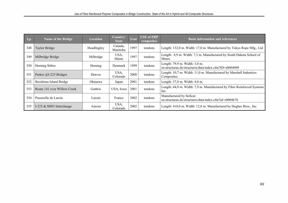
Use of Fibre Reinforced Polymer Composites in Bridge Construction. State of the Art in Hybrid and All-Composite Structures.
90
Lp Name of the Bridge Location Country/
State Year
USE of FRP
composites Basic information and references
348 Taylor Bridge Headlingley Canada,
Manitoba 1997 tendons Length: 132,0 m. Width: 17,0 m. Manufactured by Tokyo Rope Mfg., Ltd.
349 Milbridge Bridge Milbridge USA, Maine
1997 tendons Length: 4,9 m. Width: 7,3 m. Manufactured by South Dakota School of Mines.
350 Herning Stibro Herning Denmark 1999 tendons Length: 79,9 m. Width: 3,0 m. en.structurae.de/structures/data/index.cfm?ID=s0004909
351 Parker @I-225 Bridges Denver USA,
Colorado 2000 tendons
Length: 10,7 m. Width: 11,0 m. Manufactured by Marshall Industries Composites.
352 Ikeishima Island Bridge Okinawa Japan 2001 tendons Length: 37,8 m. Width: 4,0 m.
353 Route 141 over Willow Creek Guthrie USA, Iowa 2001 tendons Length: 64,0 m. Width: 7,9 m. Manufactured by Fiber Reinforced Systems Inc.
354 Passerelle de Laroin Laroin France 2002 tendons Manufactured by Soficar. en.structurae.de/structures/data/index.cfm?id=s0004676
355 I-225 & SH83 Interchange Aurora USA,
Colorado 2002 tendons Length: 410,0 m. Width: 12,8 m. Manufactured by Hughes Bros., Inc.
13. Conclusions
Fibre Reinforced Polymer Composites, thanks to their beneficial properties and
various advantages over traditional materials, have great potential as a material used in
bridge engineering. During the last 30 years, they have proved useful in a few areas:
they are commonly used to strengthen existing bridge structures; they can replace steel
as concrete reinforcement, and traditional materials for structural elements in hybrid and
all-composite bridge structures.
They exercise high specific strength and stiffness, a property particularly
interesting from the point of view of designers, as it provides the possibility to consider
new design concepts and what´s more, enables dead load savings, which is particularly
important while retrofitting existing structures by replacing old bridge decks. Their
good corrosion resistance, fatigue resistance, electromagnetic transparency and ability
to withstand harsh environment make them a good alternative for traditional materials
in particular cases, such as Lleida Footbridge crossing railway line. Thanks to
dimension stability and aesthetic appearance of FRP structural elements, they became
popular as components of small-spanned footbridges in National Parks in USA (about
170 of 355 bridges listed in chapter 12) and recently in Moscow parks and train stations.
Their light weight, enabling quick assembly without the use of heavy equipment, not
only provide cost savings, but also make them preferable to traditional materials as a
material for demountable or moveable constructions, and in cases where time-savings
are crucial, in particular when minimal traffic interruption is allowed.
However, there is a number of uncertainties and disadvantages that prevent from
justifying the use of FRP composites instead of traditional materials. Firstly, although
the majority of sources (literature) are very optimistic about the long-term durability of
FRP materials and predict lower life-cycle costs for constructions made of them, it is
not possible to justify the claims, because only a limited number of relevant projects
have been built. Much higher initial cost is also a big barrier. The second discouraging
issue is the lack of design standards. Works on such standards are said to have been
carried away for many years, but they are still far from introducing. The problem seems
to be the lack of knowledge on the material: since the properties of FRP composite
depend on the quantity and orientation of fibre reinforcement, one cannot separate the
design of the material and the design of the structure. As a result, usually the
manufacturer has to design both the material and the construction. Finally, mechanical
joints adapted from steel constructions are not appropriate for structural elements made
of anisotropic FRP and the knowledge on adhesive connections is still too little.
FRP composites can be successfully used as structural elements in particular
cases mentioned above, but they are still far from being accepted as a construction
material equal to traditional materials. More projects involving FRP composites,
especially those involving material-adapted concepts, still needed to verify their long-
term cost-saving and in-service durability.
Use of Fibre Reinforced Polymer Composites in Bridge Construction. State of the Art in Hybrid and All-Composite Structures.
91
Use of Fibre Reinforced Polymer Composites in Bridge Construction. State of the Art in Hybrid and All-Composite Structures.
92
14. Literature
[1] Bank L. C.: Composites for Construction - Structural Design with FRP Materials,
John Wiley & Sons, Inc., 2006
[2] Tuakta C.: Use of Fiber Reinforced Polymer Composite in Bridge Structures,
Massachusetts Institute of Technology, 2005
[3] Keller T.: Use of Fibre Reinforced Polymers in Bridge Construction, IABSE
Structural Engineering Documents No 7. 2003
[4] Lopez-Anido R., Naik T.: Emerging Materials for Civil Infrastructure. State of the
Art, American Society of Civil Engineers, 2000
[5] Zobel H.: Mosty kompozytowe, 50. Jubileuszowa Konferencja Naukowa KILiW
PAN i KN PZITB, Krynica, 2004
[6] Fiberline Design Manual, Fiberline Composites A/S, Kolding, 2003
[7] Zhou, A., Lesko, J.: Introduction to FRP Composites, Showcase on Virginia Fiber-
Reinforced Polymer Composites: Materials, Design, and Construction, Bristol, Virginia,
2006
[8] Jara Mori G.A., Estudio de la aplicabilidad de materiales compuestos al diseno de
estructuras de contención de tierras y su interacción con el terreno, para su empleo en
obras de infraestructura viaria - Tesis doctoral, Universidad Politécnica de Madrid,
E.T.S. de Ingenieros de Caminos, Canales y Puertos, Departamento de Ingeniería y
Morfología del Terreno, Madrid 2008
[9] Piggott M., Load bearing fibre composites, Kluwer Academic Publishers, 2002
[10] www.quakewrap.com/frppapers/Composite-Materials-For-Bridge-Construction.pdf
[11] Diego Villalón A., Gutiérrez Jiménez J.P., Arteaga Iriarte A., López Hombrados
C., Utilización de materiales compuestos en la construcción de nuevos puentes,
Instituto de Ciencias de la Construcción Eduardo Torroja, Madrid
[12] www.ettechtonics.com
[13] www.empa.ch/plugin/template/empa/*/55458/---/l=2
[14] www.fiberline.com
[15] www.strongwell.com
[16] www.bedfordplastics.com
[17] www.creativepultrusions.com
[18] www.bbr.com.sg
[19] Luke S.; Canning L.; Collin S.; Knudsen E.; Brown P.; Talstjen B.; Oloffson I.:
Advanced Composite Bridge Decking System: Project ASSET, Structural Engineering
International, no. 5/2002, p. 76-79
[20] Zobel H., Karwowski W.: Kompozyty polimerowe w mostownictwie – pomosty
wielowarstwowe, Międzynarodowa Konferencja Mosty, Kielce 2005, p. 61-74
[21] Guide specifications for design of FRP pedestrian bridges, American Association
of State Highway and Transportation Officials, Washington 2008
Use of Fibre Reinforced Polymer Composites in Bridge Construction. State of the Art in Hybrid and All-Composite Structures.
93
[22] Zobel H., Karwowski W.: Połączenia kompozytowych elementów konstrukcji
mostowych, Archiwum Instytutu InŜynierii Lądowej Politechniki Poznanskiej, no.
2/2007, p. 187-199
[23] Keller, T. Material tailored use of FRP composites in bridge and building
construction, Swiss Federal Institute of Technology Lausanne, Switzerland, 2006.
[24] www.apatech.ru
[25] Mossakowski P., Wróbel M., Zobel H., śółtowski P.: Pedestrian steel arch bridge
with composite polymer deck, IV International Conference on „Current and future
trends in bridge design, construction and maintenance", Kuala Lumpur, Malaysia,
October 2005
[26] Zhao L., Burgueño R., La Rovere H., Seible F., Karbhari V., Preliminary
evaluation of the hybrid tube bridge system, Report No. TR-2000/4, California
Department of Transportation under Contract No. 59AO032, 2000.
[27] Knippers, J. and Gabler, M., New Design Concepts for Advanced Composite
Bridges - The Friedberg Bridge in Germany, IABSE Report, Vol. 92, 2007, 332-333
[28] Sobrino, J. A., Pulido, M.D.G.: Towards Advanced Composite Material
Footbridges, Structural Engineering International IABSE 12(2) 2002: 84-86.
[29] www.bath.ac.uk/ace/uploads/StudentProjects/Bridgeconference2009/Papers/
/SKINNER.pdf
[30] Burgoyne, C. J.; Head, P.R., 1993. Aberfeldy Bridge – an advanced textile
reinforced footbridge, TechTextil Symposium, Frankfurt, Paper No. 418.
[31] www.ngcc.org.uk
[32] www.fhwa.dot.gov
[33] www.mdacomposites.org/mda
[34] www.structurae.de


![A Review on Natural Fibre Reinforced Polymer Composites · natural fibre reinforced polymer composites increase with increasing fibre loading. Khoathane et al. [1] found that the](https://img.pdfslide.us/doc/110x75/5e21837fc2d50e18910e61ca/a-review-on-natural-fibre-reinforced-polymer-composites-natural-fibre-reinforced.jpg)