Embed Size (px)
Citation preview
Creep in fibre-reinforced polymer mat composites
D. W. A. Rees, A. F. Garner and S. Dix
School of Engineering and Design, Brunel University,Uxbridge, Middlesex, UB8 3PH
Summary
Tensile creeps have been conducted upon a woven, glass-fibre laminated epoxy composite
and a 0/90° cross ply, carbon fibre reinforced epoxy composite. For the laminate loading was
aligned with a fibre direction. For the ply the loading was inclined to the fibres (off-axis).
Testing to stress levels up to 200 and temperatures in the range 20°- 200°C has
revealed a form of creep in each material. The creep observed is essentially primary in
nature but with extended time •1000 h, it may exhaust or resemble a pseudo-secondary
regime with a low rate. Where the load carrying capacity is lost, through fibre breakage or
tab slip, the creep rate accelerates suddenly to infinity in a few hours. Smooth creep curves
apply to successful tests but many irregular curves resulted from grip failure. A
phenomenological approach was used to model smooth curves using a summation of
instantaneous, primary and secondary strain terms. For the mat reinforcement a consistent
trend was not found between the secondary creep rate and a stress that was raised
incrementally upon the same testpiece. However the cumulative instantaneous strain
provided the correct elastic modulus. Creep in the solid laminate was believed to be due to a
fibre straightening that yielded a limiting strain in a time beyond which the process exhausts.
Creep in cfrc was only evident when the fibres were inclined to the stress axis, indicating a
viscous flow in the matrix. Moreover, it is believed that a viscous shear sliding between
laminates or plies is more likely to contribute to an off-axis deformation mode which is not
strain limited.
List of symbols
A Area
B isochronous plot constant
E elastic modulus
K, m secondary creep rate constants
T temperature
g engineering strain
© creep strain rate
F nominal stress
J shear stress
2 inclination
W load
Subscripts
a asymptote
c creep
l gauge length
o instantaneous
p primary
s secondary
x extension
E epoxy
T Tufnol
Introduction
A review of deformation in oriented thermoplastics has shown that anisotropy is known to
influence their creep behaviour [1]. For example, the 100 s isochronous modulus in LDPE
fell fivefold for a 45/ orientation to the draw axis compared to that aligned with this axis [2].
The subject of creep in oriented, reinforced composites has received less attention compared
to that of polymers. The few publications on the subject, as reviewed in [3], show that strain
magnitudes can be many orders lower as might be expected when strong, brittle fibres are
arranged to support the load. In a polyester laminate, for example, the instantaneous elastic
strain was 0.75% and the creep strain accumulated to just 0.2% in 1000 hr at 20/C in air
under a stress of half its tensile strength [4]. In fact, the reinforcement was introduced to
polymers in order to eliminate their troublesome dimensional instability under moderately
low loading. Ceramic fibres: glass, boron and carbon fibres are strong, elastic and brittle and
apart from their elastic strain, are otherwise inextensible. Consequently, individual fibres
themselves display a negligible plastic or a viscous (time-dependent) strain [5]. Thus creep
may be almost entirely eliminated when continuous fibres are aligned with the stress
direction [6]. Kevlar reinforcement is less creep resistant as this natural fibre will continue to
extend under load, even at room temperature [7]. Consequently, a unidirectional kevlar
reinforced epoxy creeps with contribution to the time dependent strain from both the fibre
and matrix. Under investigation here is the general question of whether creep can be said to
creep occurs in polymer matrices reinforced with ceramic fibres in unidirectional and matt
arrangements. The subject has potential significance wherever composites components are
used in more aggressive environments where stress and temperature can become abnormally
high, as for bearing, aerospace and pressure vessel applications.
Previous work, though sparse, has suggested [6] that creep does arise when load is inclined to
fibres embedded in an epoxy matrix. Both uni-directional and cross-ply, glass-
reinforcements showed optimum amounts of creep when inclinations were between 40° and
60°. Here the creep compliance increased with time up to 100 h at these critical orientations
and expectantly this would be accentuated with increased temperature from what is
documented on creep in the polymer matrix material [6]. In the extreme case a chopped
strand random mat is far more dependent upon the creep resistance of the matrix [8].
Similarly, the nature and orientation of fibres in a plate have little influence upon a loaded lap
joint between plates bonded with an polymer resin. Shear within the latter is almost entirely
responsible for the time dependent flow in the joint [9]. Further design data for reinforced
composites in applications where creep and fatigue endurance is required are reviewed in [10,
11].
Experimental
Test Methods
Two single lever creep machines each with a load ratio of 10:1 were used as described in
[12]. A mounted extensometer was used at room temperature calibrated to chart
displacements continuously in a small displacement range • 2mm. A remotely sited, 10 mm
transducer, with a displacement magnification 8:1, was employed for raised temperature
testing. Lower temperatures up to 80°C were reached with hot air blowers. For higher
temperatures two reflective electrical heating elements were hinged with back plates to the
machine columns, so allowing adjustment to the air gap on either side of the testpiece. With
the insulation used to minimise heat losses, each method allowed the temperature to be raised
and maintained around the testpiece. A chromel-alumel thermocouple (Type K) centred at the
gauge length recorded temperature showed an acceptable ± 2°C variation. Loads were
applied in increments to achieve the desired stress level and then left for long periods until
creep had variously (i) expired, (ii) attained its steady rate or (iii) resulted in a fracture. In a
few tests a continued incremental loading pattern was adopted with 50 h intervals though to
fracture. In view of the small displacements found, the stress and strain given are nominal or
engineering definitions F = W/A and g = x/l, where W is the applied load, A is the section
area, x is the displacement upon a reference length of l. The latter was taken as either 50 mm
between knife-edges or the distance (100 and 150 mm) between end-reinforcing tabs
respectively for displacements measured by the extensometer and transducer methods above.
The grips were serrated and of sufficient width to be clamped with 4 bolts, two on either side
of the end tabs. The assembly was pinned through the grips to the loading bars to avoid any
bending. Alignment with the load axis was ensured with the connection of the top bar to a
universal joint which hung from the load lever that pivoted upon knife edges.
Materials
The Tufnol (type 10G/40) was supplied by Radio Spares with a 0/90° woven glass fibre as a
1.93 mm thick sheet of size 285 × 590 mm. The sheet is constructed from layers made by
impregnating the woven glass with polyester resin before being stacked together, then heated
under pressure to produce a cured solid. With a high fibre content (• 60 %) its cross
breaking strength of 150 MPa is retained to 250 °C. Testpieces were cut with diamond
coated circular saw into strips 12 mm wide × 250 mm long, with the 0° fibres lying parallel
to the load. The 50 mm end lengths were reinforced with 1 mm thick, 0/90°glass fibre
reinforced (Permalli) epoxy composite tabs glued to both sides with epoxy resin so that their
fibres lay at ± 45° orientations to the load. Later, these were replaced with 1.5 mm
aluminium alloy tabs, glued with a ceramic adhesive, to allow a pin to be inserted through the
testpiece and grips and so prevent slip at higher test temperatures.
The 0°/90° carbon fibre reinforcement material was supplied by a collaborating company
(TVR Pontinia, Italy) as an experimental 1.5 mm sheet for this creep study. In this material
individual fibres were hand lain in the two directions before impregnation with epoxy resin
and a post cure resulted in a 60 % fibre volume fraction with an a relatively irregular spacing,
compared to a woven mat. Though certain areas in the sheet were resin rich this production
method maintains straight fibres as is preferable for improved creep resistance. Strips 12.5
mm wide × 200 mm long (BS 2782: Part 3) were cut from the sheet with their axes parallel
to its 0°, 30°, 45° and 90° direction. Testpieces were prepared by bonding 50 mm long soft
aluminium alloy ends tabs with a ceramic epoxy adhesive to expose a 100 mm gage length.
These showed that the tensile strength in the 0°- directions at 320 MPa was twice that for the
90°- direction. The corresponding elastic moduli were 15 and 10 GPa. A minimum strength
and stiffness of 100 MPa and 3.5 GPa respectively applied to a testpiece with ± 45° fibre
orientations. The methods of gripping and heating testpieces for creep testing were identical
to those employed for Tufnol.
It was instructive to conduct a series of further creep tests at similar test temperatures upon a
epoxy resin thermoset, representative of the matrix material. Samples were cut from a sheet
of epoxy resin (Araldite CT200) and filed to a standard dumbell shape with 10 mm × 4 mm
cross-section dimensions and 65 mm parallel length. Each 60 h creep test was conducted
with a new testpiece and short-time isochronous plots were found from a repeated load-
unload at 100 s intervals.
Theoretical
There are many empirical formulae available to describe one or more stages of the creep
curve. The time dependence of creep strain has expressed variously in parabolic,
logarithmic, hyperbolic and exponential forms [13]. The latter is preferred to represent the
smooth creep curves, as revealed from this investigation, with the following three-part
formula:
(1)
where t is elapsed time following an instantaneous elastic strain response to the stress applied
i.e. g o = F/E. The second and third terms are the contributions to total strain g from primary
and secondary creep. Within these terms is the observed secondary creep rate and m and
gp are constants expressing an exponential decay in the primary creep strain. Equation (1)
appears to have been first employed by Garofalo [14] and Andrade [15] in the early 1960's
but exclusively for metals: stainless steel and cadium respectively. The form of eq (1) is also
predicted from Burger’s four element model of visco-elasticity, this model being previously
applied to creep strain observed in glass reinforced polyester when times run into years [16].
In parallel with a phenomenological approach used to describe creep in metals, a similar
method will be adopted here to describe creep in composites. That is, the constants in eq (1)
are found from two points lying on the primary curve at times t1 and t2 (t2 > t1). Thus, from
eq(1) the creep strain contributions to total strain at each time are:
(2)
(3)
Equations (2) and (3) may be solved for m and g p. For convenience, two points are taken
equally separated in time, so that t2 = 2t1 to give:
(4a)
(4b)
A second exponential function was used to represent isochronous stress versus creep strain
data pertaining to a given time (the isochronous plot):
(5)
where Fo is the stress level to initiate creep, Fa is the asymptotic stress level in the
isochronous plot of F versus gc. It will be seen for composites with a creep strain asymptote,
that the function B = B(T, t) is a weakly sensitive time and temperature dependent parameter.
Thus, the strain dependence upon stress, time and temperature is expressed connected within
eqs (1) and (5). Normally a family of constant stress creep curves is required over the full
creep stress range to establish an isochronous plot but the time and material expended on this
can be circumvented by conducting a single incremental stress test across the stress range.
When a similar shortcut is taken with polymers an intermediate strain recovery period must
follow creep, i.e. a load-unload procedure is followed. Here, the superposition principle
shows that most, but never all, of the creep strain will recover if a similar periods of creep
and recovery are allowed. Thus, the next increased stress level may be taken to be applied to
a virgin testpiece. In composites, where the creep strain is very much smaller, the recovered
strain is essentially equal to go, i.e. it is the initial elastic strain that recovers immediately. As
with a polymer, any further recovery observed over time in a composite is attributed to visco-
elasticity in its matrix. Damage through fibre breakage, delamination and de-bonding is
attributed to the strain that cannot recover. In fact, if such damage occurred the resulting loss
in stiffness (i.e. a lower modulus E) would result in a greater amount of elastic recovered
strain since g = F/E! With a dominant elastic strain in recovery the suggestion is that no
intermediate recovery periods are required when seeking an isochronous plot by a shortened
method. Instead a simple incremental loading may be adopted subtracting out go from each
curve given that the cumulative effect of these would equal the total elastic strain recovered
upon removal of all loading.
Results and Discussion
Epoxy Matrix
For reference, Figure 1 shows three curves and their associated stress levels F that promote
significant creep strain at room temperature (18°C) in a representative matrix material. The
decreasing primary creep rate eventually settles into a fairly constant secondary strain rate
after 40 h. A similar creep behaviour (not shown) was observed when hor air blowers raised
the test temperature to 76°C. Within the limited ranges of stress employed at the two
temperatures, the logarithm of (%/h) plotted linearly with F (MPa) to give a common
exponential law:
(6)
At 18°C: m = 0.082 and K = 79.4 × 10! 6. At 76°C: m = 0.23 and K = 4.16 × 10! 6 in these
units. The average elastic moduli, based upon 100 s strains, at the two temperatures were
found to be 4.6 GPa and 1.6 GPa respectively.
Tufnol
Not all tests resulted in smooth creep curves particularly at the higher temperatures of testing
(see Fig. 2). We might expect a stepped curve when the load is suddenly increased, as with
curve 2, in Fig. 2 but an explanation is necessary where strain steps occur under a constant
load (e.g. curve 4). Here, it appears that an accelerating creep rate is arrested for 200 h before
a further acceleration burst to when the material finally fails to hold the load. Such behaviour
was found with a partial loss in load bearing area through a gripping failure. In this case as
the grip pressure was insufficient the material adjacent to the grip pin had failed. A similar
failure applied to curve 5. Curve 7 was the result of de-lamination in the scorched outer
layers capacity arising from radiant heating. Once these initial testing difficulties had been
overcome failures thereafter occurred in the central test length and occasionally near the tabs.
This more desirable outcome from the testing resulted in the families of long time creep
curves given in Figures 3 and 4. The incremental load programme employed sufficiently long
time intervals whereupon creep had either exhausted or a very slow steady rate had been
achieved. These curves follow one another in a time sequence 1, 2, 3 . . . 6 but each curve
has been re-based to time t = 0 at its corresponding intercept stain go. In fact, it appears that
the greatest amount of creep occurred within curve 1 in each figure, where, it is believed,
conditions were adequate for all fibre straightening within the weave to occur. Despite some
variation in the average temperature for these tests, there is clearly evidence that the
subsequent steady rates observed never exceeded this initial rate. The load increases
succeeded in regenerating a short-lived primary region but not in raising significantly,
except at the highest stress level which resulted in a sudden fibre-breakage, as evident within
the sudden rise in strain in curve 6 of each figure. An extended tertiary region of increasing
strain rate, common in many metals, did not appear in a polyester laminated composites [4],
which is confirmed here among the valid test results. As for the mechanism of failure, a fibre
matrix de-bonding leads to resin cracking and ultimately to fibre fracture The stress levels
that result in damage of this kind are lessened with time when the environment is aggressive
and at higher temperatures a viscous flow in the matrix also contributes to the structural
degradation.
As an example of the application of eq (3) to describe the creep curve 1 for the material in
Fig. 4, we apply eqs (4a,b) with t1 = 50 h and = 1.67 × 10! 6 h!1 to find the constants gp =
1.41 × 10 !3 and m = 0.0275. Predicted creep strains at t = 400 h and 800 h are 0.21 % and
0.28 % to which we add an initial elastic strain of 0.625 %.
The increased creep rates within curves A and B in Fig. 4 refer to a test in which a 1 mm hole
had been introduced at its centre. The stress concentration (•3) and the discontinuity in the
fibres around the hole enhance the rate as fewer fibres within the adjacent ligaments become
more highly stressed. For this reason the drilling of composites in the fabrication of load
bearing structures is inadvisable, especially in higher temperature applications. The
performance of alternative bonding methods that do not interrupt the fibre continuity should
be sought [9].
Figure 5 refers to a series of 70 h tests in which a new testpiece was used for each creep
curve at an average temperature of 77°C. These curves do reveal a consistent increase in
their instantaneous elastic loading strains and in their steady creep rates with stress level.
The rates from all tests (Figs 3 - 5) are plotted against stress on the double logarithmic axes
in Fig. 6. It appears that only those rates derived from Fig. 5 show a monotonic increase over
the shorter test duration but otherwise there are no clear trends for a 0°/90° woven mat where
the 0° fibres are aligned with the stress axis. However, it can be said that across all
temperatures the creep rates (i) are generally low ( < 4 × 10!4 %/h) for stress levels below
100 MPa, (ii) are enhanced by stress concentration (see points A and B) and (iii) can decline
to near-zero given sufficient time, in which case the curve is wholly primary in the strict
sense.
The shorter-time incremental load programs are shown schematically in Fig. 7. Temperature
were altered as the heaters allowed and stress levels were raised under equal load increments
to result in failure. Again these curves reveal that creep strain is small relative to the elastic
strain initially but the two strains become comparable when high stress levels are reached.
Plotting the cumulative elastic strain versus stress across all tests (Fig. 8) provided an average
modulus E = 28 GPa. In this figure there also appears the 50 and 90 h isochronous creep
strain versus stress plots from the four incremental creep families. The isochronous data,
which shows that creep requires a stress level greater than 50 MPa to appear, falls within a
narrow band at these two times despite the temperature differences. These data are contained
by eq(5) for Fa = 300 MPa and B-values of 200 and 250 as shown.
A relationship giving the ratios between moduli of filled and unfilled polymer equates to that
between their compliances [17]. For the epoxy (E) composite Tufnol (T) We write this as:
(7)
Applying this to our 50 h isochronous creep data at 76°C in Fig. 8 gives the compliance ratio
as CE /CT = 0.59/0.13 • 4.5 and using the elastic moduli quoted ET /EE = 28/1.6 = 17.5.
Clearly eq (7) is not appropriate to a laminated mat for its most creep resistant orientation..
Carbon-Fibre
Preliminary incremental loadings (not shown) of carbon-fibre mat reinforced epoxy aligned
with the 0°- fibre showed that steady creep rates were very low at 18°C: 1.2 × 10! 4 %/h for F
= 70 MPa and 3.3 × 10! 4 %/h at 180 MPa. These are similar to those found for Tufnol and
are •200 times less than those for epoxy. At an increased temperature (75°C) the creep rate
was raised by one order to 2.2 × 10! 3 %/h under a stress level (170 MPa) approaching the
fracture stress (200 MPa). The elastic moduli E at 18°C and 75°C were 15.4 GPa and 14.4
GPa respectively, these being about one half E for Tufnol and 3 and 9 times greater than E
for epoxy at similar temperatures. This negligible amount of creep strain is to be expected
with many inextensible, straight fibres aligned with the load. Whilst the transverse fibres do
not contribute to the creep resistance under this loading they do so when load is inclined to
the mat. The results for off-axis creep testing at 18°C are shown in Figs 9 and 10 for various
orientations and stress levels. Figure 9 shows how creep deformation is enhanced by
increasing orientations up to 45° under a constant stress of 50 MPa. The steady rates increase
by one order from •1 × 10! 4 %/h to 2 × 10! 3 %/h. Figure 10 shows how deformation is
similarly enhanced by one order through increasing stress levels from 50 MPa to 80 MPa for
a constant 45° orientation. Here the steady creep rates (%/h) are 1.97, 2.45 and 2.76 (×10!3
). Those rates (%/h) in epoxy at similar stress and temperature are found from eq(6) to be 4.8
× 10! 3, 1.1 × 10! 2 and 5.6 × 10! 2, i.e. the 45°- fibres reduce these rates by 2.4, 4.5 and 20,
which are far less impressive then the reduction found from aligned 0°- fibres.
Applying eq(7) to our creep data at 18°C in Figs. 1 and 10 gives a compliance ratio CE/CT =
0.52/0.47 • 1 and using the elastic moduli quoted ET /EE = 15.4/1.6 • 9.5. Once again eq (7)
is not appropriate when all the fibres succeed in doing for this orientation is to raise the
elastic stiffness without enhancing the creep resistance.
To see how the off-axis creep arises, let the 0° and 90° fibres lie with respective inclinations
to the stress axis of 2 and 2 + 90°, as shown in Fig. 11a. The inclination induces a complex
stress state along the 0°/90° fibres and consequently, within the island of resin captured
between them. This stress state follows from a standard transformation of the inclined,
applied tensile stress F into the fibre directions [18]. For the co-ordinate system shown, two
normal and two shear stress components align with the fibres as follows:
(i) F2 = F sin22 tension applied to all 90° fibres
(ii) F1 + 90 = F cos22 tension applied to all 0° fibres
(iii) J2 = J 2 + 90 = ½ F sin22 complementary shear parallel to both 0° and 90° fibres
These stress components cause the fibres to separate and rotate. The compatible deformation
within the matrix is thus a combination of (i) direct strain due to fibre separation and (ii)
distortion resulting from fibre rotation. The two effects, separated in Figs 11b and c, show
how an impregnated material lying in the region ABCD between fibres, distorts in shear and
deforms under normal tension/compression. That is, for the given orientation (2 = 60°), and
allowing for the Poisson effect, the displacement between parallel fibres AD and BC (Fig.
11b) results in a slight compression and that between AB and CD in a greater tension. The
relative magnitude of these two normal strains become equal when 2 = 45°, but will remain
small with fibres of high stiffness. The rotation of the fibres into the parallelogram in Fig.
11c reveals a shear strain that expresses a change to the right angle ABC as a radian measure.
The fibres offer little resistance to a shear mode of deformation. The latter must therefore be
accommodated largely by the polymer matrix with a susceptibility to creep.
This simplified analysis shows that maximum normal stress components apply to 2 = 45°:
F45° = F135° = J45° = F/2. In Fig. 9 the effective (von Mises) stress remains constant at a
magnitude equal to F for all 2 and therefore it does not control creep. The fact that the creep
strain depends upon 2 in this figure and that there is negligible creep for 2 = 0°, suggests that
viscous flow in the matrix is controlled largely by the complementary shear stress component
in (iii). Normal tensile stresses (i) and (ii) play a role in separating the fibres elastically to
allow shear to occur particularly when they act in equal magnitude upon the 45° and 135°
planes of maximum shear as in Fig. 10. Here it appears that a critical value of the applied (or
effective) stress controls fracture, this stress being at its minimum for 0/90° mat with a 45°
orientation to the stress axis [19]. As with creep fracture research upon metals [20] it would
become necessary to employ multi-axial stress to distinguish between maximum principal
stress and effective stress control of fracture in composites. The interdependence between
components of the biaxial stress state transformed from an off-axis tensile test cannot enable
such a distinction.
Conclusions
Creep in an epoxy matrix can be almost eliminated by aligning embedded fibres with the
stress direction. Deformation is essentially instantaneously elastic with woven mat fibres
having raised the stiffness by a tenfold amount. However, the straightening of woven fibres
with time under stress complements elasticity and gives a pseudo creep curve. Where fibres
and stress axes are misalignment creep becomes more of an issue to structural integrity and
dimensional stability as the matrix material behaves in a viscous manner. Both 0°/90°fibre
orientations in a mat arrangement will impede “off-axis” flow more effectively than a uni-
directional reinforcement where fibres are free to slide with the matrix flow. Shear appears
to be the controlling factor apparent from a 0°/90°a fibrous structure with a 45° misalignment
to stress that is least resistant to creep. Here, depending upon the stress level, the
reinforcement succeeds in reducing creep rates in the matrix by a factor less than 20. In
contrast, a further ten-fold reduction applies when one set of fibres align with the stress axis.
The second set of fibres though redundant in this application would play an equally effective
role under biaxial stress and, as we have seen contribute to off-axis creep resistance. Mat
reinforced composites retain these creep resistant properties in their favourable orientations
for temperatures up to 150°C despite a minor reduction in stiffness.
References
1. Gittus, J. Creep, Viscoelasticity and Fracture in Solids, Applied Science, 1975.
2. Darlington, M. W. and Saunders, D. W. Creep in oriented thermoplastics, Jl Macromol.
Sci. Phys, 1971, B5 (2), 207-218.
3. Johnson, A. F. Engineering Design Properties of GRP, BPF/NPL Pub No. 215/3 4-86,
1986.
4. Howe, R. J. Cumulative Damage of a Glass Reinforced Plastic, Ph.D. thesis University of
Nottingham 1971.
5. Pearson, S. Creep and recovery of a mineral glass at normal temperatures, Jl Soc. Glass
Tech, 1952, 36, 105-114.
6. Sturgeon, J. B. Creep of fibre reinforced thermosetting resins, in: Creep of Engineering
Materials, Ed. C.D.Pomeroy, I. Mech.E. 1978, 175-195.
7. Ericksen, R. H. Room temperature creep of Kevlar 49-epoxy composites, Composites,
1976, 7, 189-194.
8. Holmes, M. and Just, D. J. GRP in Structural Engineering, 1983, Applied Science,
Elsevier.
9. Reis, P. N. B., Ferreira, J. A. M., Costa, J. D. M. and Richardson, M. O. W. Creep
behaviour of PP/glass fibre composite adhesive lap joints, Key Engineering Materials, 1002,
230-232, 315-318.
10. Brown, L. M. Proc: Fatigue and Creep of Composite Materials (Eds Lilholt H. and
Talreja, R.) 1982, Risø Nat Lab, Denmark, p.1.
11. Hancox, N.L. and Mayer, R.M. Design Data for Reinforced Plastics, Chapman and Hall,
1994.
12. Rees, D. W. A. Nutting creep in mono- and bi-layer polymers, Plastics, Rubbers and
Composites, 2002, 31(8), 350-358.
13. Crawford, R. J. Plastics Engineering, Butterworth-Heinemann, 2002
14. Garofalo, F. Fundamentals of Creep and Creep Rupture in Metals, Macmillan, 1965.
15. Andrade, E. N. da C. and Aboav, D.A. The flow of polycrystalline cadium under simple
shear, Proc Roy Soc., 1964, A280, 353.
16. Ehrenstein, C.W. Creep and relaxation in glass reinforced unsaturated polyesters,
Kunststoffe, 1976, 66, 289-294.
17. Neilsen, L.E. and Landel, R. F. Mechanical Properties of Polymers and Composites,
Marcel Dekker, p.422, 1994
18. Rees, D. W. A. Basic Solid Mechanics, Macmillan, 1997.
19. Agarwal, B.D. and Broutman, L. J. Analysis and Performance of Fibre Composites,
Wiley-Interscience, 1980.
20. Hayhurst, D. R. Creep rupture under multi-axial states of stress, Jl Mech Phys Solids,
1972, 20, 381.
List of Figures
Figure 1 Creep curves for an epoxy resin thermoset (Araldite CT100) at 18°C.
Figure 2 Irregular creep curves for Tufnol at medium stress levels and moderately high
temperatures.
Figure 3 Creep curves for Tufnol under similar test conditions to Fig. 2 showing low, steady
creep rates. Loading incremental following long time intervals.
Figure 4 Further creep curves for Tufnol showing repeatable behaviour. Conditions similar
to those of Fig. 3 except that curves A and B show the effect of a 1 mm diameter cross-bore
upon creep rate at low stress levels.
Figure 5 Creep curves for Tufnol at 77°C using a new testpiece per test.
Figure 6 Correlation between steady creep rates and stress for all tests.
Figure 7 Incremental loading of Tufnol showing elastic and creep strain responses from

increasing stress levels to fracture.
Figure 8 Isochronous creep plots for Tufnol at 50 h and 90 h fitted by eq 5. Separated elastic
strain shows an average elastic modulus of 28 GPa within the temperature range.
Figure 9 Effect of fibre orientation upon creep in 0/90° cfr epoxy at 18°C. Stress level,
constant at 50 MPa, has three different inclinations to 0° fibre.
Figure 10 Effect of stress level upon creep in 0/90° cfr epoxy at 18°C. Fibre orientation,
constant at 45°, has its least to creep.
Figure 11 (a) Uni-axial stress F with inclination 2 to 0°-fibre induces a combined normal
and shear stress state shown aligned with 0/90° fibres. Correspondingly, the matrix region
ABCD deforms with the direct and shear strain shown in (b) and (c).
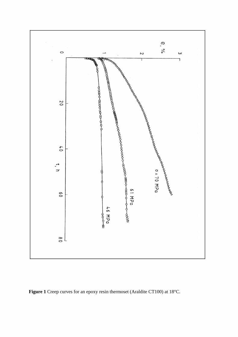
Figure 1 Creep curves for an epoxy resin thermoset (Araldite CT100) at 18°C.

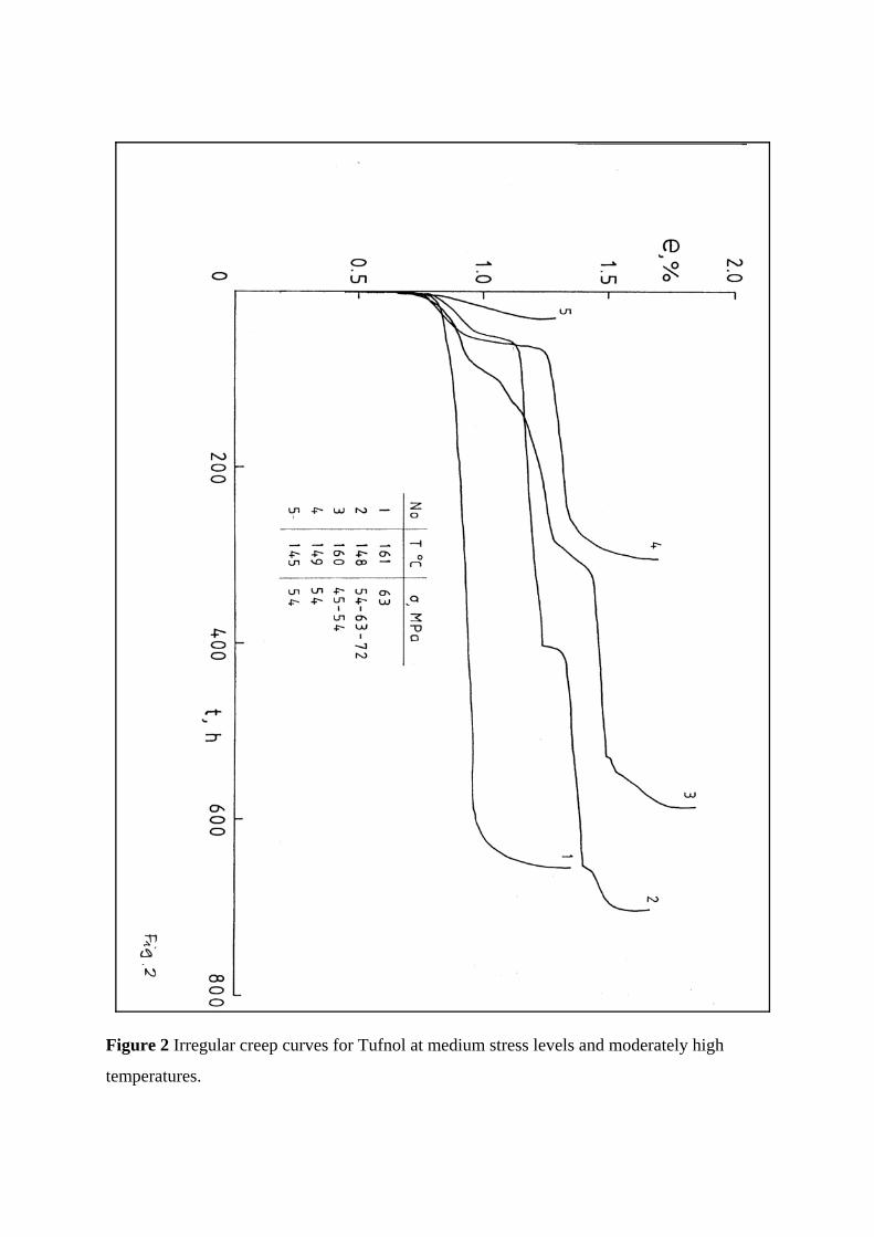
Figure 2 Irregular creep curves for Tufnol at medium stress levels and moderately high
temperatures.
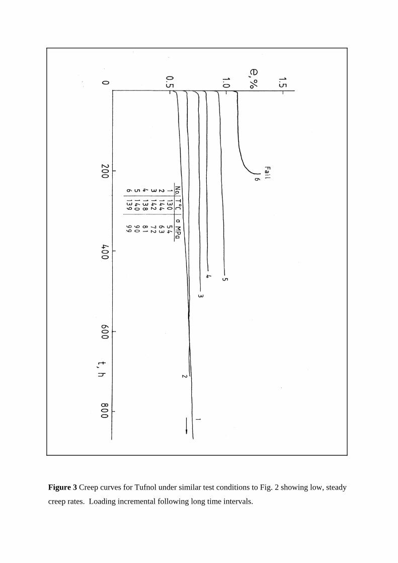
Figure 3 Creep curves for Tufnol under similar test conditions to Fig. 2 showing low, steady
creep rates. Loading incremental following long time intervals.
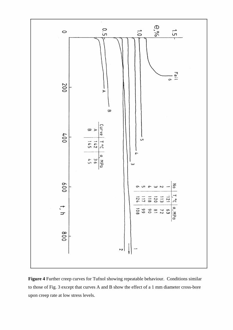
Figure 4 Further creep curves for Tufnol showing repeatable behaviour. Conditions similar
to those of Fig. 3 except that curves A and B show the effect of a 1 mm diameter cross-bore
upon creep rate at low stress levels.
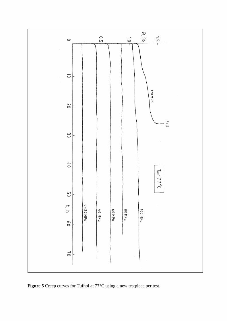
Figure 5 Creep curves for Tufnol at 77°C using a new testpiece per test.
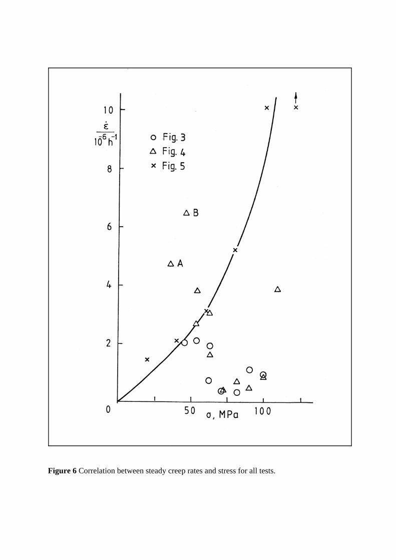
Figure 6 Correlation between steady creep rates and stress for all tests.
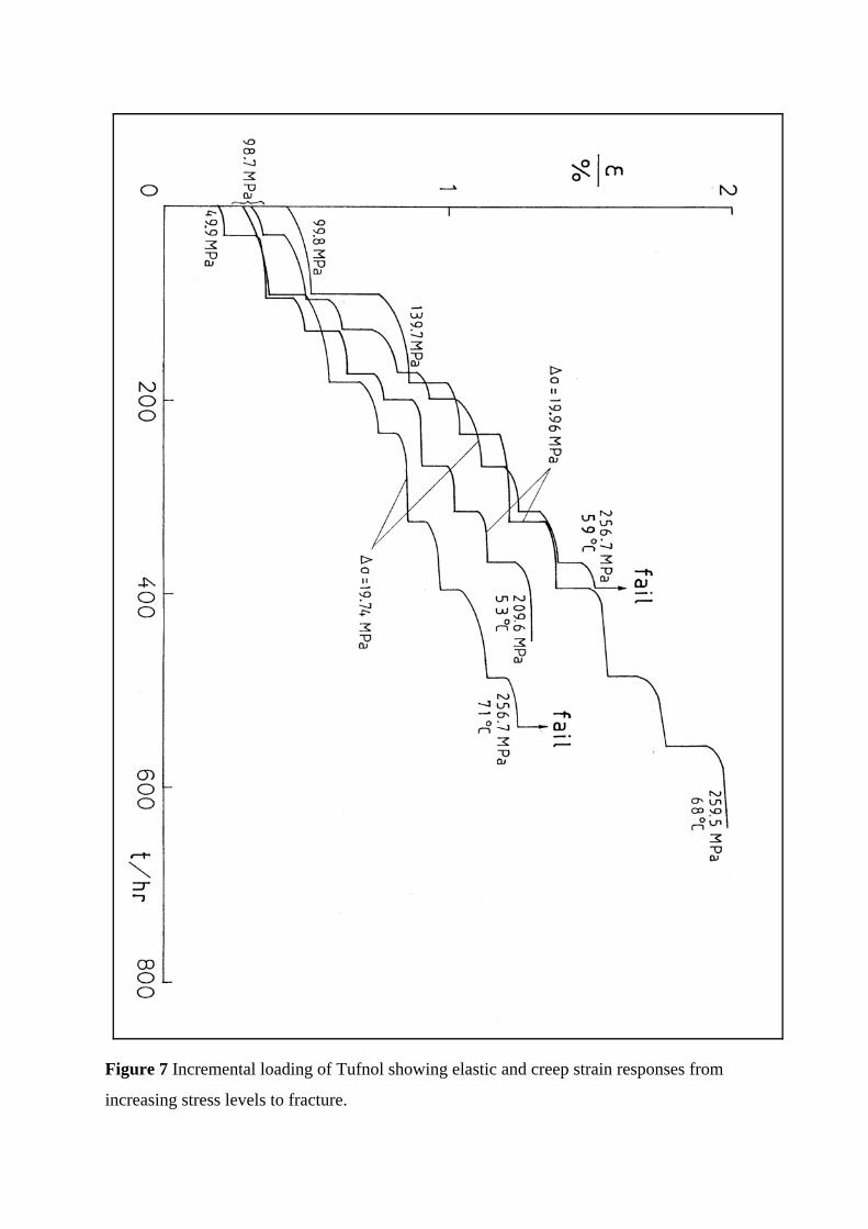
Figure 7 Incremental loading of Tufnol showing elastic and creep strain responses from
increasing stress levels to fracture.
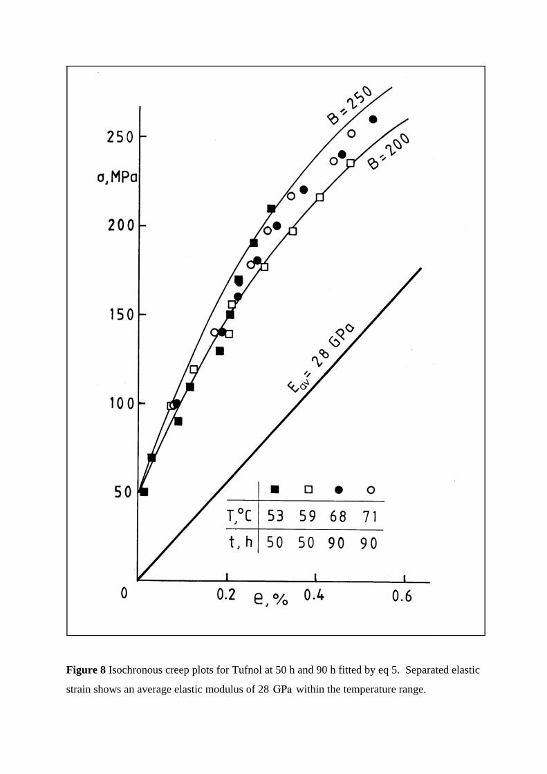
Figure 8 Isochronous creep plots for Tufnol at 50 h and 90 h fitted by eq 5. Separated elastic
strain shows an average elastic modulus of 28 within the temperature range.
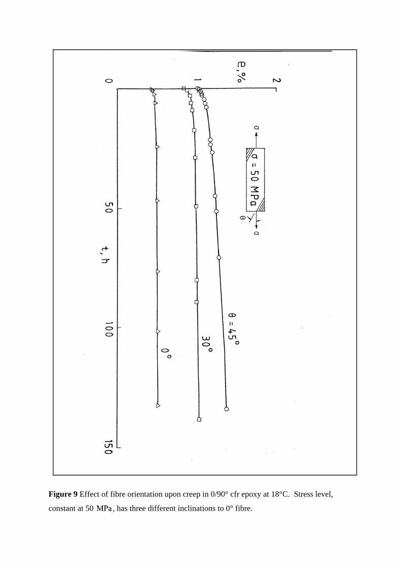
Figure 9 Effect of fibre orientation upon creep in 0/90° cfr epoxy at 18°C. Stress level,
constant at 50 , has three different inclinations to 0° fibre.
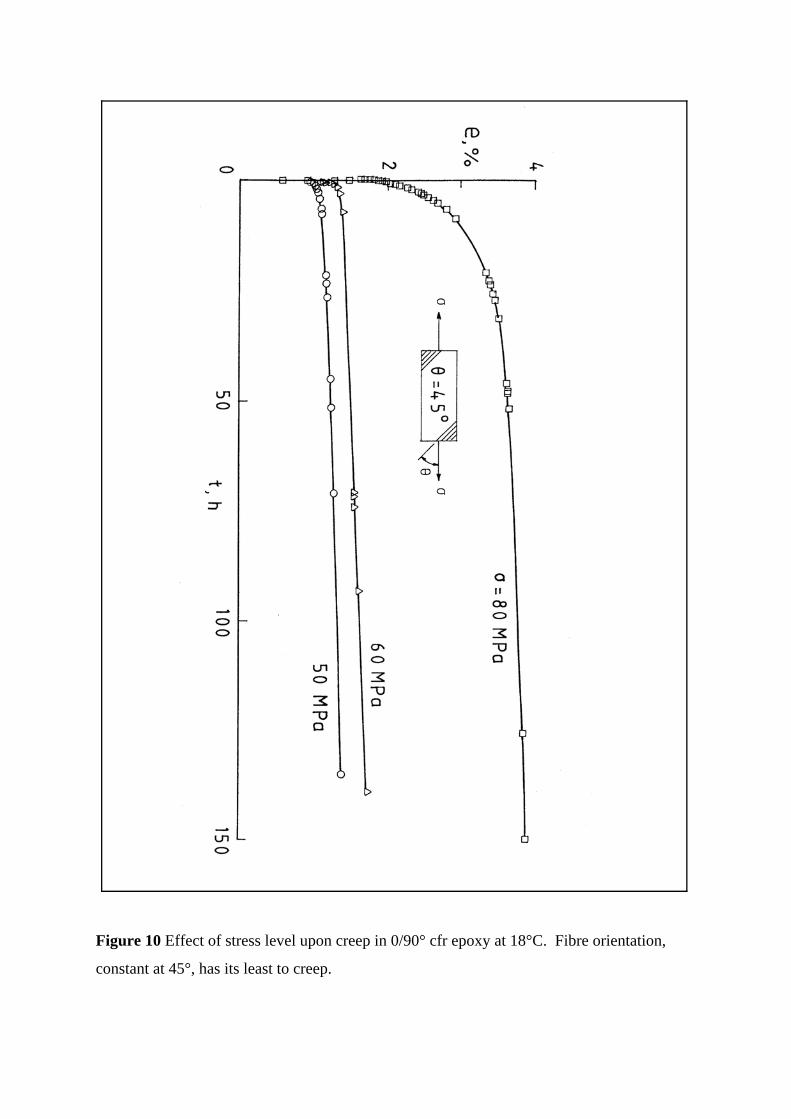
Figure 10 Effect of stress level upon creep in 0/90° cfr epoxy at 18°C. Fibre orientation,
constant at 45°, has its least to creep.
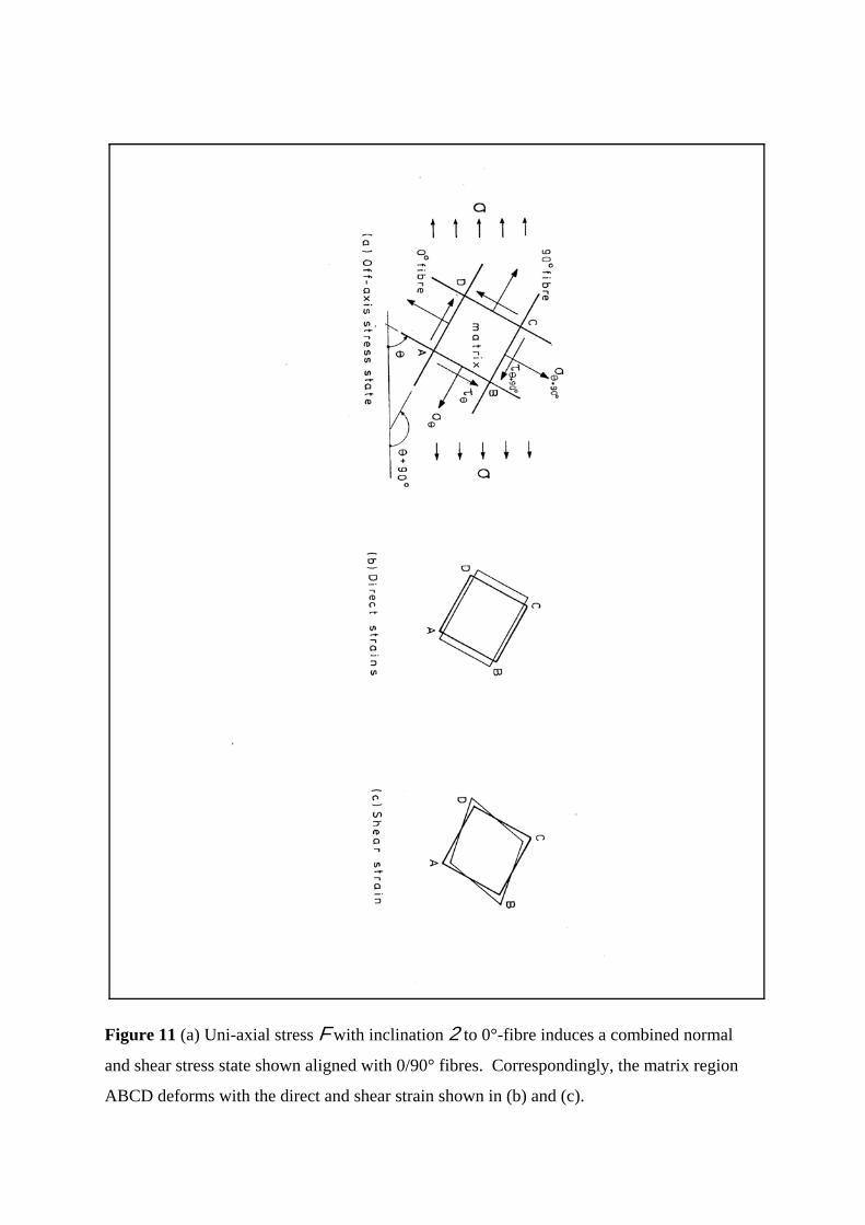
Figure 11 (a) Uni-axial stress F with inclination 2 to 0°-fibre induces a combined normal
and shear stress state shown aligned with 0/90° fibres. Correspondingly, the matrix region
ABCD deforms with the direct and shear strain shown in (b) and (c).