Embed Size (px)
Citation preview
IA-32 Architecture
ECOM 2325
Computer Organization and Assembly Language
Presentation Outline
Basic Computer Organization
Instruction Execution Cycle
IA-32 Registers
IA-32 Memory Management
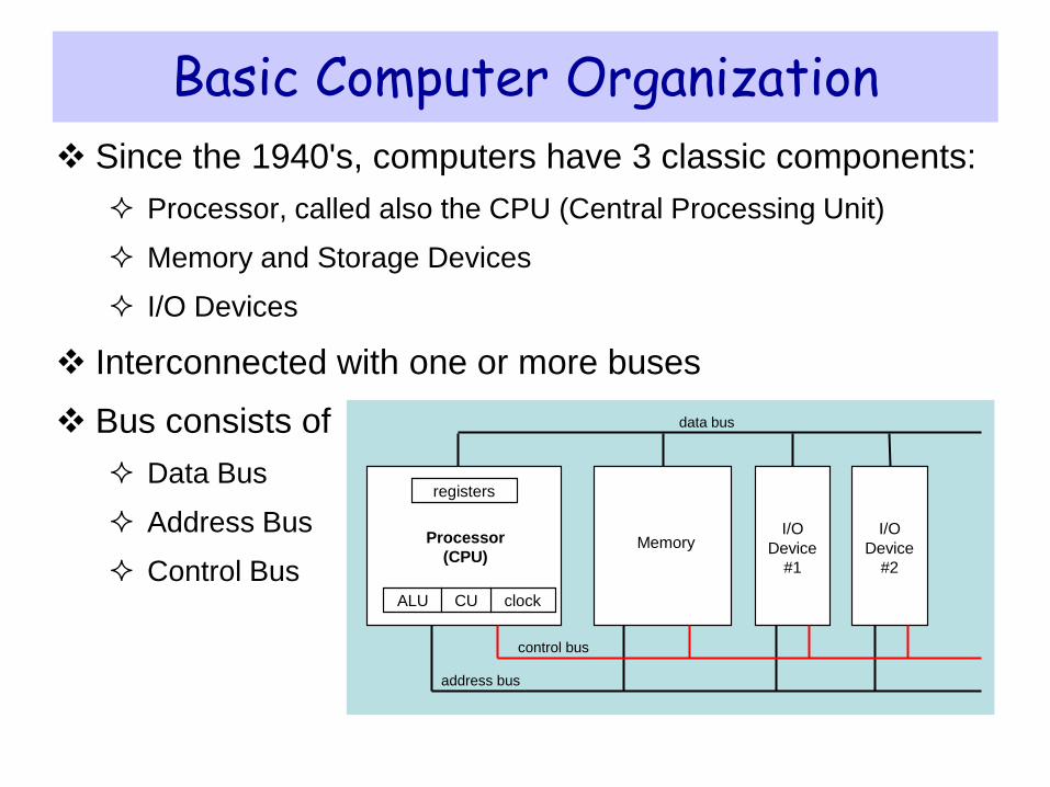
Basic Computer Organization
Since the 1940's, computers have 3 classic components:
Processor, called also the CPU (Central Processing Unit)
Memory and Storage Devices
I/O Devices
Interconnected with one or more buses
Bus consists of
Data Bus
Address Bus
Control Bus
Processor
(CPU) Memory
registers
ALU clock
I/O
Device
#1
I/O
Device
#2
data bus
control bus
address bus
CU
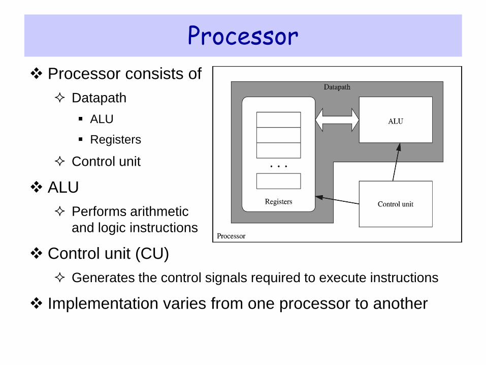
Processor consists of
Datapath
ALU
Registers
Control unit
ALU
Performs arithmetic
and logic instructions
Control unit (CU)
Generates the control signals required to execute instructions
Implementation varies from one processor to another
Processor
Memory
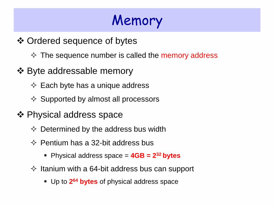
Ordered sequence of bytes
The sequence number is called the memory address
Byte addressable memory
Each byte has a unique address
Supported by almost all processors
Physical address space
Determined by the address bus width
Pentium has a 32-bit address bus
Physical address space = 4GB = 232 bytes
Itanium with a 64-bit address bus can support
Up to 264 bytes of physical address space
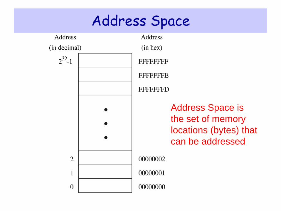
Address Space
Address Space is
the set of memory
locations (bytes) that
can be addressed
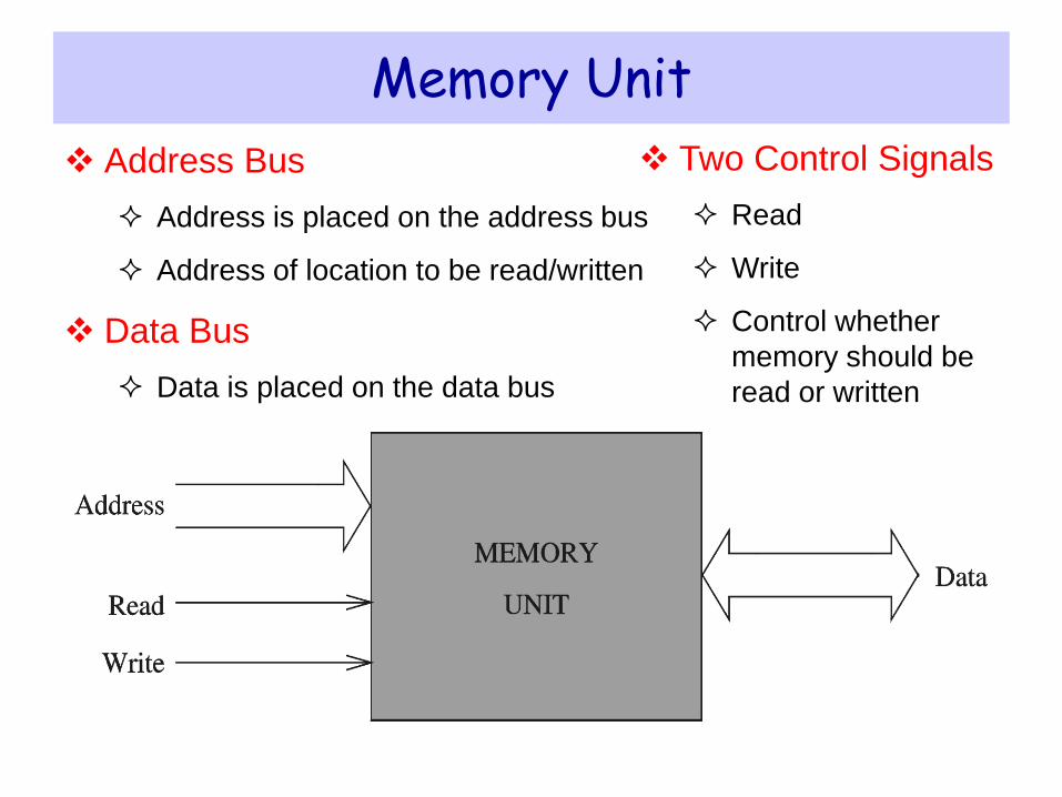
Memory Unit
Address Bus
Address is placed on the address bus
Address of location to be read/written
Data Bus
Data is placed on the data bus
Two Control Signals
Read
Write
Control whether
memory should be
read or written
Next ...
Basic Computer Organization
Instruction Execution Cycle
IA-32 Registers
IA-32 Memory Management
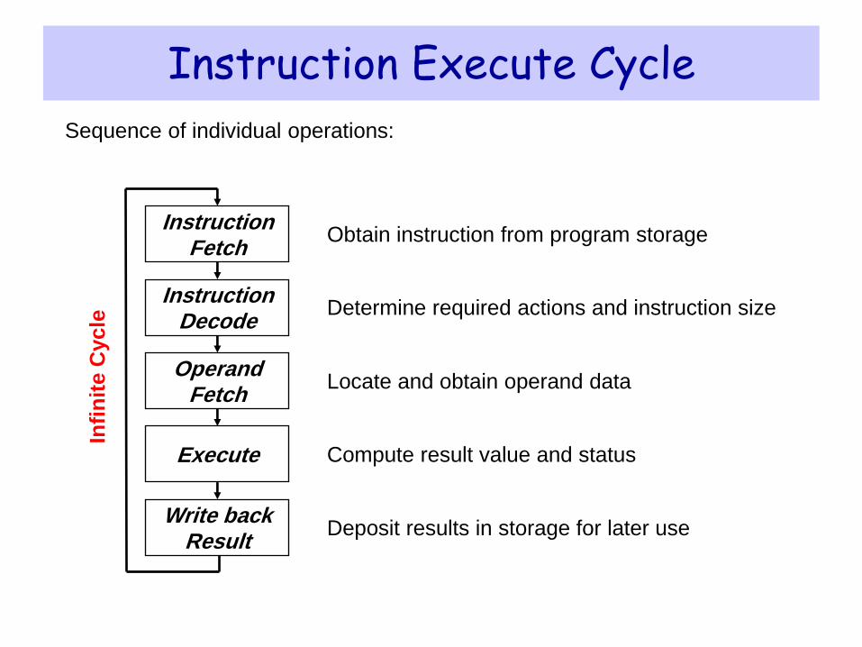
Instruction Execute Cycle
Obtain instruction from program storage
Determine required actions and instruction size
Locate and obtain operand data
Compute result value and status
Deposit results in storage for later use
Instruction Decode
Instruction Fetch
Operand Fetch
Execute
Write back Result
Infi
nit
e C
ycle
Sequence of individual operations:
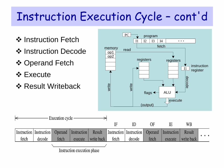
Instruction Execution Cycle – cont'd
Instruction Fetch
Instruction Decode
Operand Fetch
Execute
Result Writeback
I2 I3 I4
PC program
I1 instruction register
op1 op2
memory fetch
ALU
registers
write
de
co
de
execute
read
write
(output)
registers
flags
. . . I1
Next ...
Basic Computer Organization
Intel Microprocessors
IA-32 Registers
Instruction Execution Cycle
IA-32 Memory Management
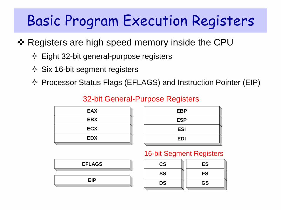
Basic Program Execution Registers
CS
SS
DS
ES
EIP
EFLAGS
16-bit Segment Registers
EAX
EBX
ECX
EDX
32-bit General-Purpose Registers
FS
GS
EBP
ESP
ESI
EDI
Registers are high speed memory inside the CPU
Eight 32-bit general-purpose registers
Six 16-bit segment registers
Processor Status Flags (EFLAGS) and Instruction Pointer (EIP)
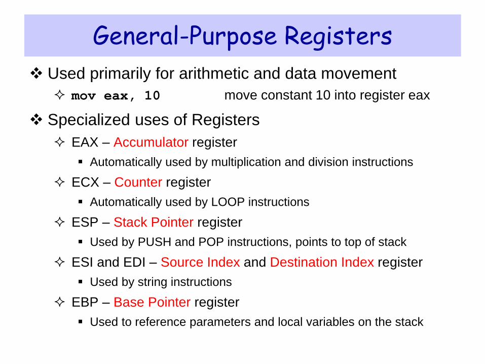
General-Purpose Registers
Used primarily for arithmetic and data movement
mov eax, 10 move constant 10 into register eax
Specialized uses of Registers
EAX – Accumulator register
Automatically used by multiplication and division instructions
ECX – Counter register
Automatically used by LOOP instructions
ESP – Stack Pointer register
Used by PUSH and POP instructions, points to top of stack
ESI and EDI – Source Index and Destination Index register
Used by string instructions
EBP – Base Pointer register
Used to reference parameters and local variables on the stack
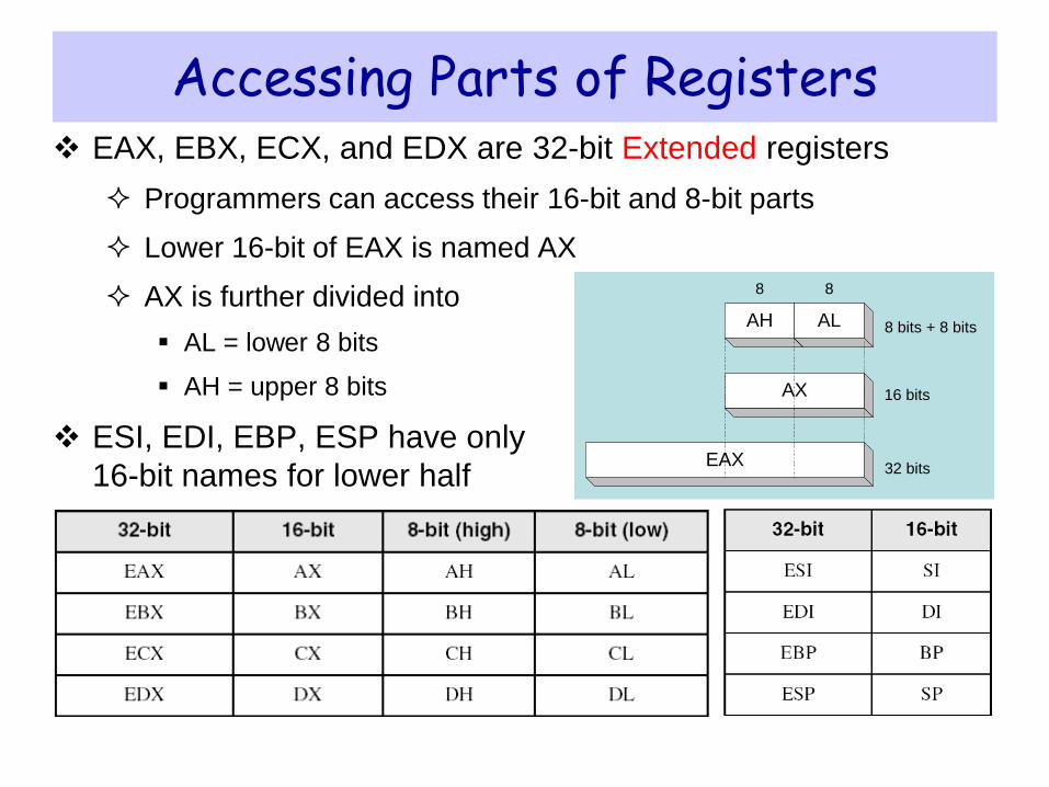
Accessing Parts of Registers EAX, EBX, ECX, and EDX are 32-bit Extended registers
Programmers can access their 16-bit and 8-bit parts
Lower 16-bit of EAX is named AX
AX is further divided into
AL = lower 8 bits
AH = upper 8 bits
ESI, EDI, EBP, ESP have only
16-bit names for lower half
AH AL
16 bits
8
AX
EAX
8
32 bits
8 bits + 8 bits
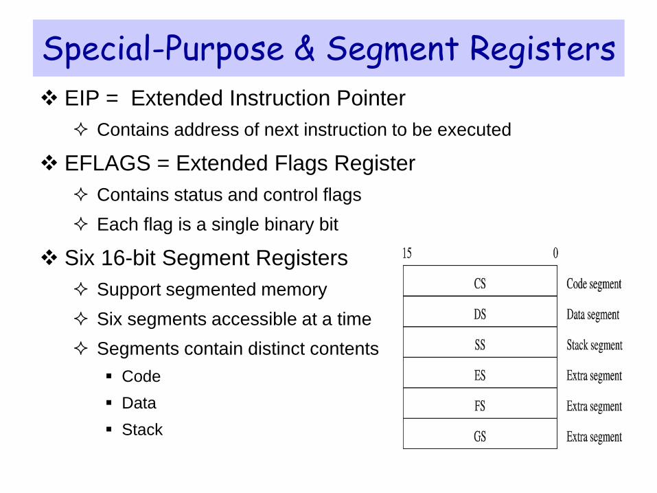
Special-Purpose & Segment Registers
EIP = Extended Instruction Pointer
Contains address of next instruction to be executed
EFLAGS = Extended Flags Register
Contains status and control flags
Each flag is a single binary bit
Six 16-bit Segment Registers
Support segmented memory
Six segments accessible at a time
Segments contain distinct contents
Code
Data
Stack
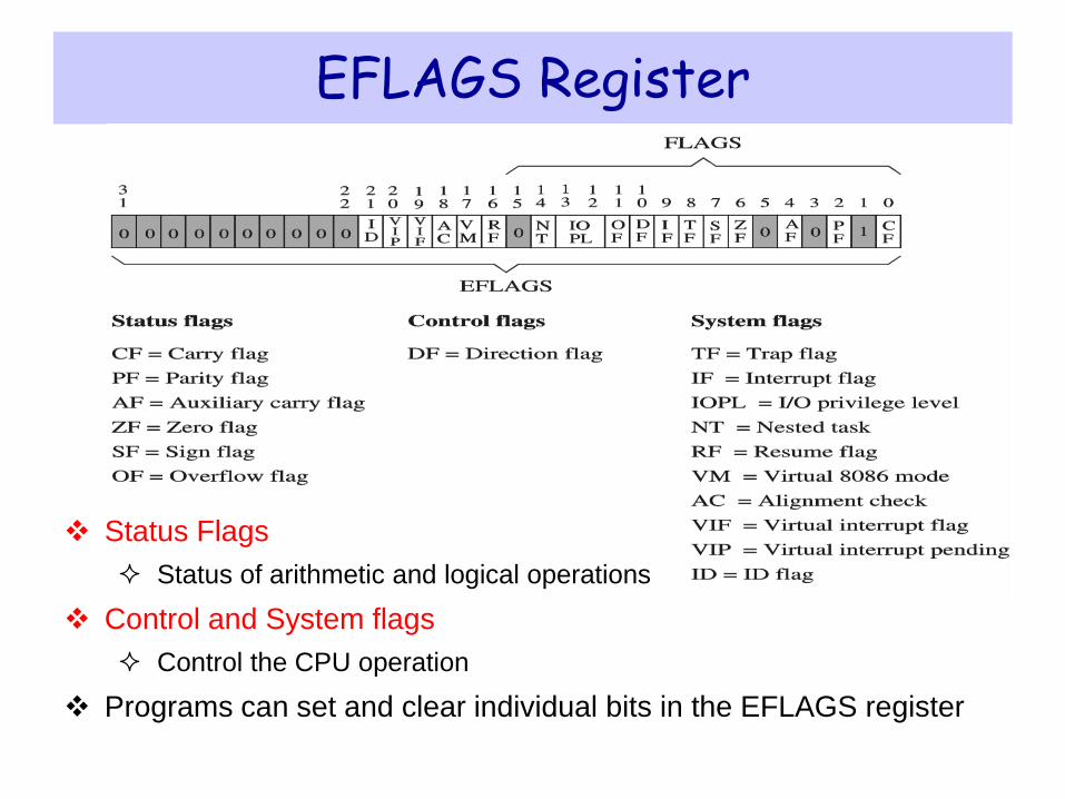
EFLAGS Register
Status Flags
Status of arithmetic and logical operations
Control and System flags
Control the CPU operation
Programs can set and clear individual bits in the EFLAGS register
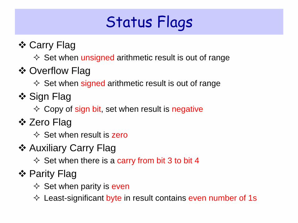
Status Flags
Carry Flag
Set when unsigned arithmetic result is out of range
Overflow Flag
Set when signed arithmetic result is out of range
Sign Flag
Copy of sign bit, set when result is negative
Zero Flag
Set when result is zero
Auxiliary Carry Flag
Set when there is a carry from bit 3 to bit 4
Parity Flag
Set when parity is even
Least-significant byte in result contains even number of 1s
Next ...
Basic Computer Organization
Instruction Execution Cycle
Intel Microprocessors
IA-32 Registers
IA-32 Memory Management
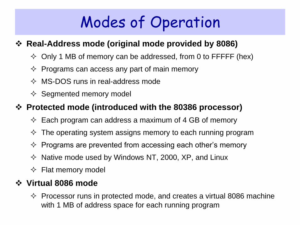
Modes of Operation Real-Address mode (original mode provided by 8086)
Only 1 MB of memory can be addressed, from 0 to FFFFF (hex)
Programs can access any part of main memory
MS-DOS runs in real-address mode
Segmented memory model
Protected mode (introduced with the 80386 processor)
Each program can address a maximum of 4 GB of memory
The operating system assigns memory to each running program
Programs are prevented from accessing each other’s memory
Native mode used by Windows NT, 2000, XP, and Linux
Flat memory model
Virtual 8086 mode
Processor runs in protected mode, and creates a virtual 8086 machine
with 1 MB of address space for each running program
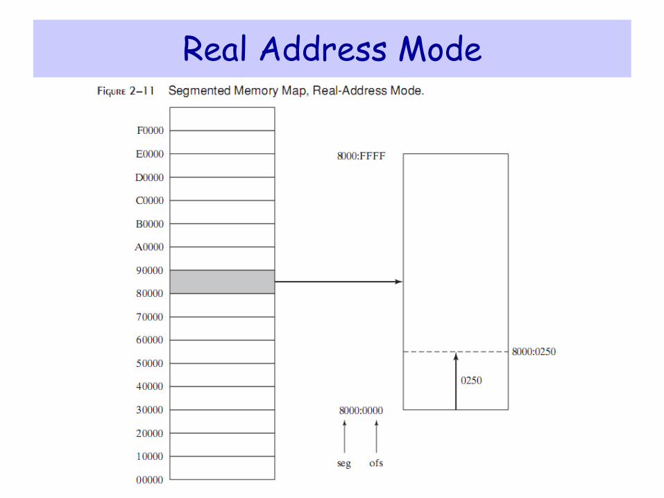
Real Address Mode
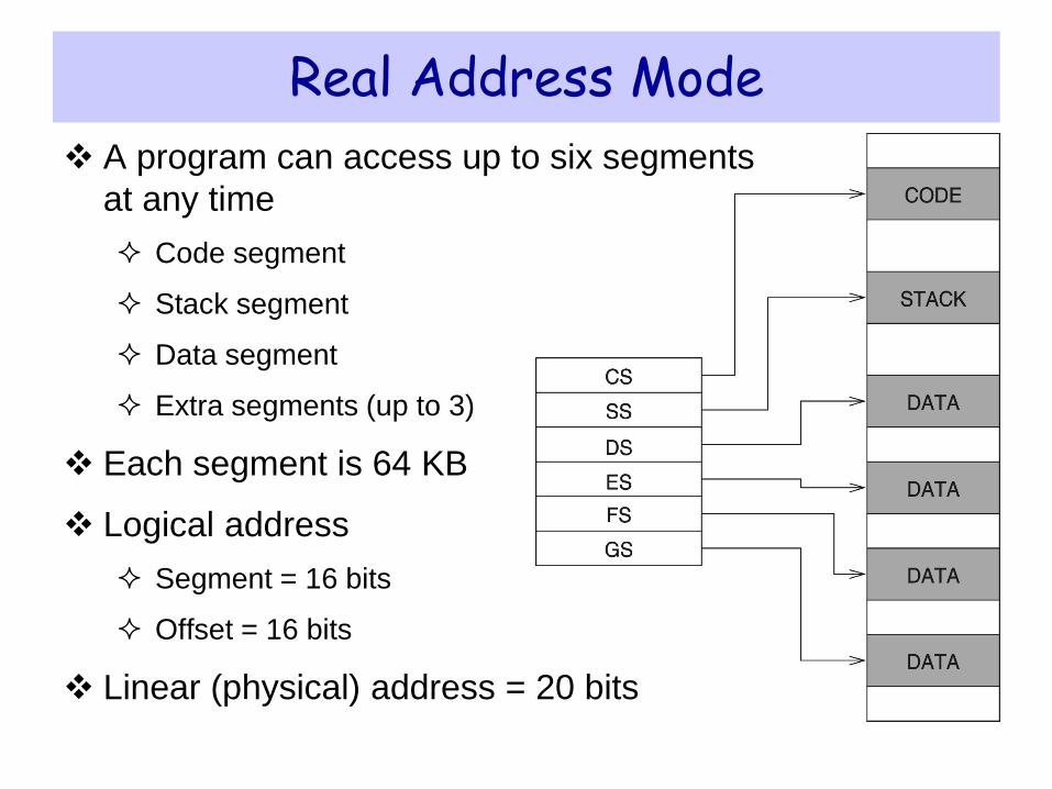
Real Address Mode
A program can access up to six segments
at any time
Code segment
Stack segment
Data segment
Extra segments (up to 3)
Each segment is 64 KB
Logical address
Segment = 16 bits
Offset = 16 bits
Linear (physical) address = 20 bits

Logical to Linear Address Translation
Linear address = Segment × 10
(hex) + Offset
Example:
Suppose a variables logical address is
A1F0:04C0
segment = A1F0 (hex)
offset = 04C0 (hex)
what is the linear address?
Solution:
A1F00 (add 0 to segment in hex)
+ 04C0 (offset in hex)
A23C0 (20-bit linear address in hex)
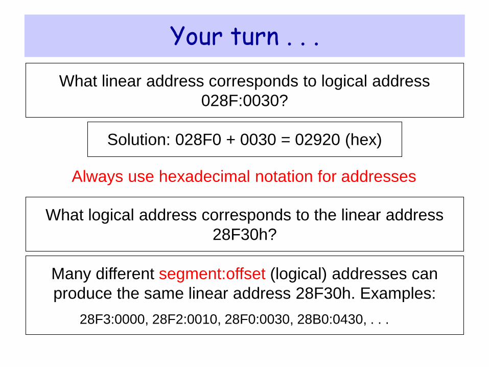
Your turn . . .
What linear address corresponds to logical address
028F:0030?
Solution: 028F0 + 0030 = 02920 (hex)
Always use hexadecimal notation for addresses
What logical address corresponds to the linear address
28F30h?
Many different segment:offset (logical) addresses can
produce the same linear address 28F30h. Examples:
28F3:0000, 28F2:0010, 28F0:0030, 28B0:0430, . . .
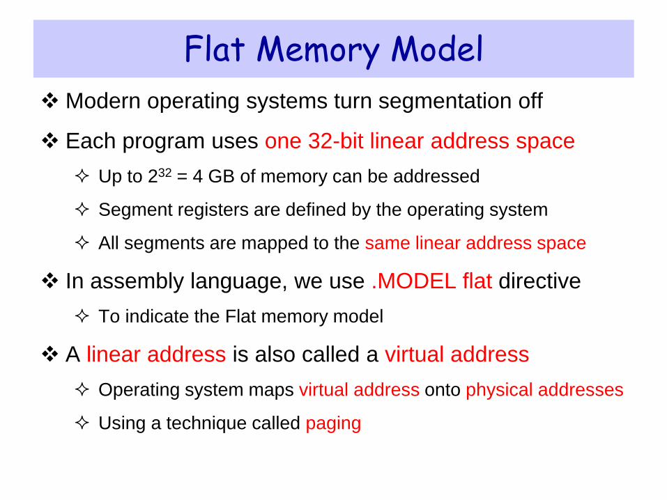
Flat Memory Model
Modern operating systems turn segmentation off
Each program uses one 32-bit linear address space
Up to 232 = 4 GB of memory can be addressed
Segment registers are defined by the operating system
All segments are mapped to the same linear address space
In assembly language, we use .MODEL flat directive
To indicate the Flat memory model
A linear address is also called a virtual address
Operating system maps virtual address onto physical addresses
Using a technique called paging


![Untitled-9 [site.iugaza.edu.ps]site.iugaza.edu.ps/kelkahlout/files/2012/02/CHAPTER2D1.docx · Web viewThere are a number of industrial efl1uents and emissions particularly poisonous](https://img.pdfslide.us/doc/110x75/5e4d16efbbf54c74dc3d8ee4/untitled-9-site-site-web-view-there-are-a-number-of-industrial-efl1uents-and.jpg)