Embed Size (px)
Citation preview
Venturing into 64-bit mode
Examining the steps needed to take the processor into IA-32e
mode -- and then back out again
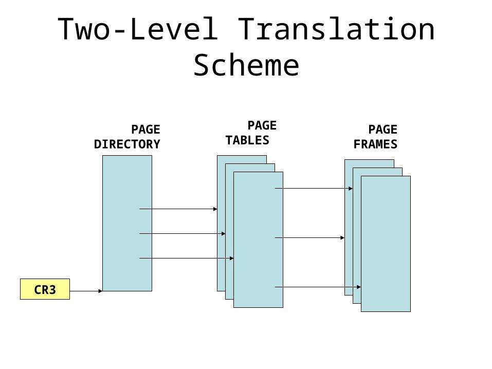
Two-Level Translation Scheme
PAGEDIRECTORY
CR3
PAGETABLES
PAGEFRAMES
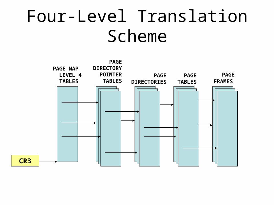
Four-Level Translation Scheme
CR3
PAGEFRAMES
PAGETABLES
PAGEDIRECTORIES
PAGEDIRECTORY POINTER TABLES
PAGE MAP LEVEL 4 TABLES
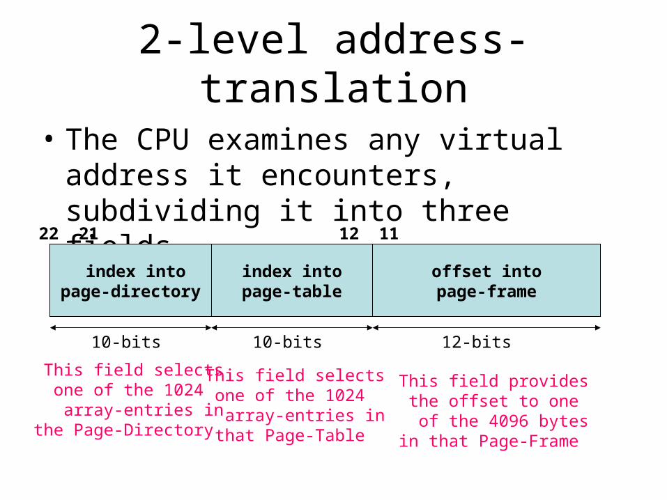
2-level address-translation
• The CPU examines any virtual address it encounters, subdividing it into three fields
offset into page-frame
index intopage-directory
index into page-table
31 22 21 12 11 0
10-bits 10-bits 12-bits
This field selects one of the 1024 array-entries inthe Page-Directory
This field selects one of the 1024 array-entries in that Page-Table
This field provides the offset to one of the 4096 bytes in that Page-Frame
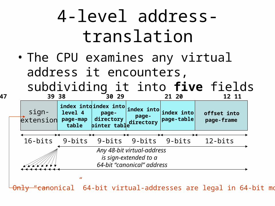
4-level address-translation
• The CPU examines any virtual address it encounters, subdividing it into five fields
offset into page-frame
index into page-table
63 48 47 39 38 30 29 21 20 12 11 0
16-bits 9-bits 12-bits
index into page-
directory
index into page-
directorypointer table
index intolevel 4
page-maptable
9-bits9-bits9-bits
sign-extension
Any 48-bit virtual-address is sign-extended to a 64-bit “canonical” address
Only “canonical” 64-bit virtual-addresses are legal in 64-bit mode
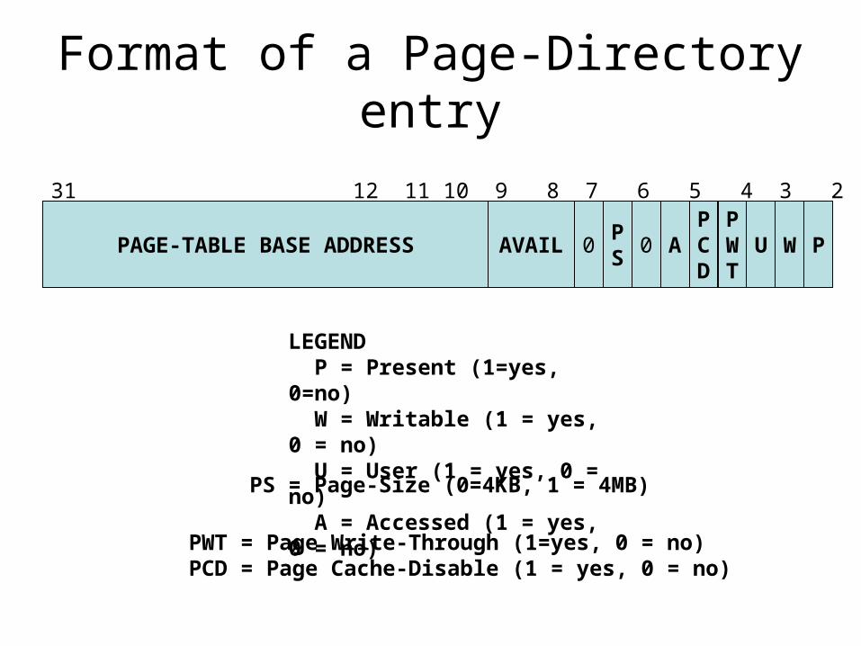
Format of a Page-Directory entry
PAGE-TABLE BASE ADDRESS PWUPWT
PCD
A0PS
0
31 12 11 10 9 8 7 6 5 4 3 2 1 0
AVAIL
LEGEND P = Present (1=yes, 0=no) W = Writable (1 = yes, 0 = no) U = User (1 = yes, 0 = no) A = Accessed (1 = yes, 0 = no)
PWT = Page Write-Through (1=yes, 0 = no)PCD = Page Cache-Disable (1 = yes, 0 = no)
PS = Page-Size (0=4KB, 1 = 4MB)
Reserved(must be 0)
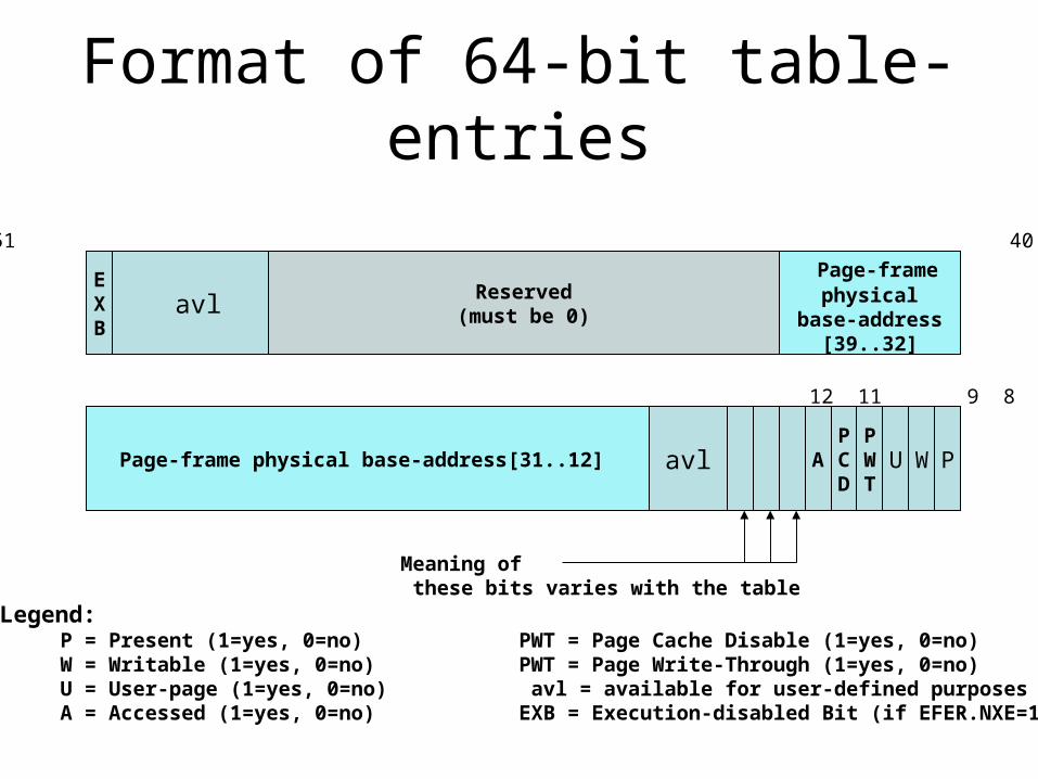
Format of 64-bit table-entries
63 62 52 51 40 39 32
31 12 11 9 8 7 6 5 4 3 2 1 0
Page-frame physical base-address[31..12]
Page-framephysical
base-address[39..32]
EXB
PWUPWT
PCD
A
avl
avl
Meaning of these bits varies with the table
Legend: P = Present (1=yes, 0=no) PWT = Page Cache Disable (1=yes, 0=no) W = Writable (1=yes, 0=no) PWT = Page Write-Through (1=yes, 0=no) U = User-page (1=yes, 0=no) avl = available for user-defined purposes A = Accessed (1=yes, 0=no) EXB = Execution-disabled Bit (if EFER.NXE=1)
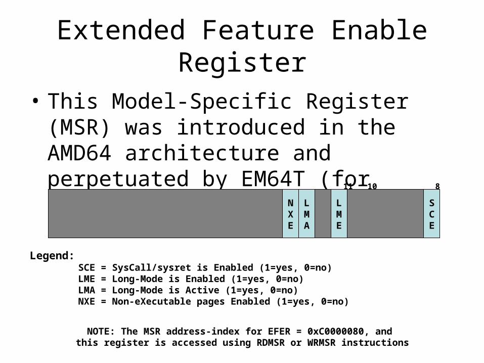
Extended Feature Enable Register
• This Model-Specific Register (MSR) was introduced in the AMD64 architecture and perpetuated by EM64T (for compatibility)
SCE
LME
LMA
NXE
63 11 10 8 0
Legend:SCE = SysCall/sysret is Enabled (1=yes, 0=no)LME = Long-Mode is Enabled (1=yes, 0=no)LMA = Long-Mode is Active (1=yes, 0=no)NXE = Non-eXecutable pages Enabled (1=yes, 0=no)
NOTE: The MSR address-index for EFER = 0xC0000080, and this register is accessed using RDMSR or WRMSR instructions
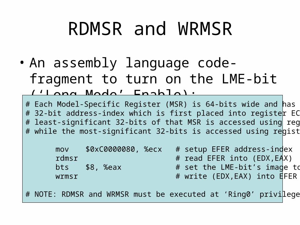
RDMSR and WRMSR
• An assembly language code-fragment to turn on the LME-bit (‘Long-Mode’ Enable):
# Each Model-Specific Register (MSR) is 64-bits wide and has a unique# 32-bit address-index which is first placed into register ECX. Then the # least-significant 32-bits of that MSR is accessed using register EAX,# while the most-significant 32-bits is accessed using register EDX.
mov $0xC0000080, %ecx # setup EFER address-indexrdmsr # read EFER into (EDX,EAX)bts $8, %eax # set the LME-bit’s image to 1wrmsr # write (EDX,EAX) into EFER
# NOTE: RDMSR and WRMSR must be executed at ‘Ring0’ privilege-level.
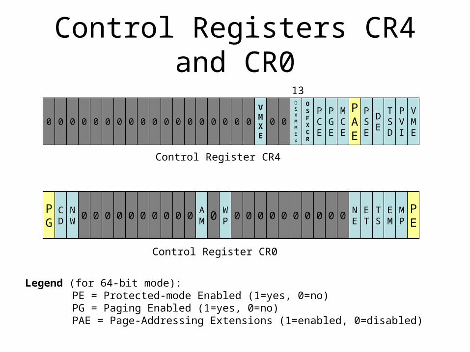
Control Registers CR4 and CR0
0 0 0 0 0 0 0 0 0 0 0 0 0 0 0 0 0 0
VMXE
0 0
OSXMMEx
OSFXCR
PCE
PGE
MCE
PAE
PSE
DE
TSD
PVI
VME
PG
CD
NW 0 0 0 0 0 0 0 0 0 0
AM 0 W
P 0 0 0 0 0 0 0 0 0 0NE
ET
TS
EM
MP
PE
31 13 5 0
31 0
Control Register CR4
Control Register CR0
Legend (for 64-bit mode):PE = Protected-mode Enabled (1=yes, 0=no)PG = Paging Enabled (1=yes, 0=no)PAE = Page-Addressing Extensions (1=enabled, 0=disabled)
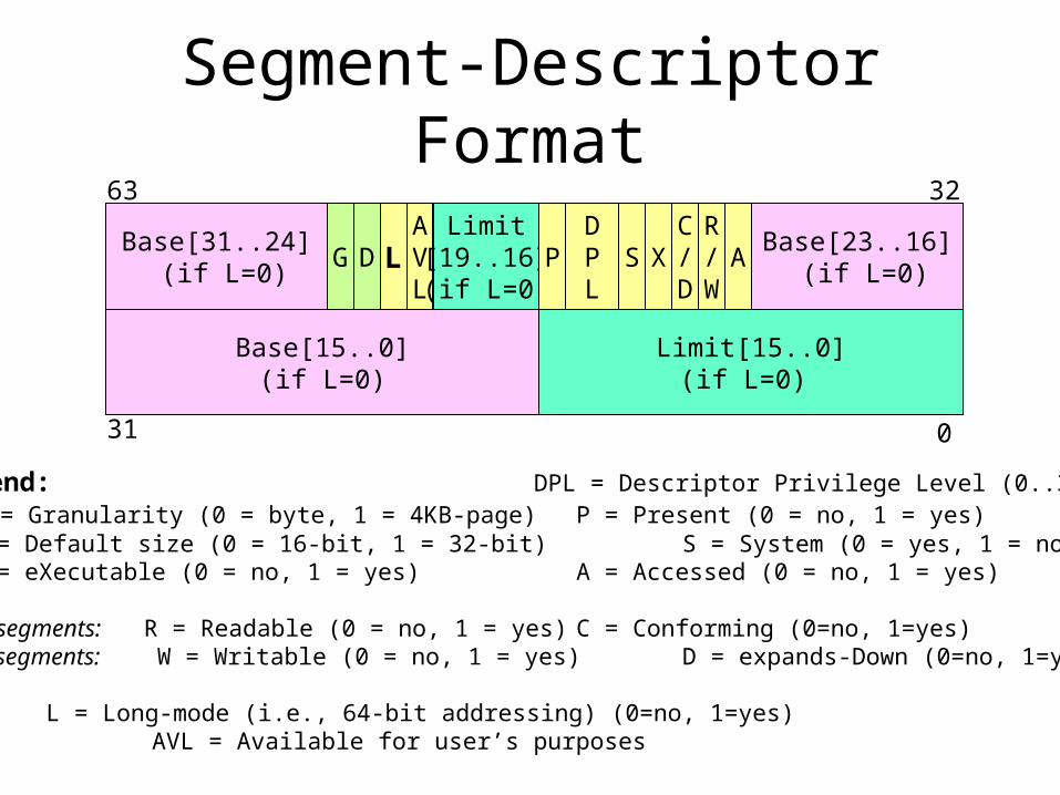
Segment-Descriptor Format
Base[31..24] (if L=0)
G D LAVL
Limit[19..16](if L=0)
PDPL
S XC/D
R/
WA
Base[23..16] (if L=0)
Base[15..0](if L=0)
Limit[15..0](if L=0)
63 32
31 0
Legend: DPL = Descriptor Privilege Level (0..3) G = Granularity (0 = byte, 1 = 4KB-page) P = Present (0 = no, 1 = yes) D = Default size (0 = 16-bit, 1 = 32-bit) S = System (0 = yes, 1 = no) X = eXecutable (0 = no, 1 = yes) A = Accessed (0 = no, 1 = yes)
code-segments: R = Readable (0 = no, 1 = yes) C = Conforming (0=no, 1=yes)data-segments: W = Writable (0 = no, 1 = yes) D = expands-Down (0=no, 1=yes)
L = Long-mode (i.e., 64-bit addressing) (0=no, 1=yes)AVL = Available for user’s purposes

IA-32e Call-Gate descriptor
Base[31..24] (if S=0)
G D LAVL
offset[31..16] PDPL
0 XC/D
R/
W
GateType
(=1100)
Reserved(must be 0)
code-segment selector offset[15..0]
127 96
31 0
offset[63..32]
Reserved (must be 0)
offset[63..32]
We can use a call-gate to ‘jump’ from 16-bit code-segment to a 64-bit code-segment
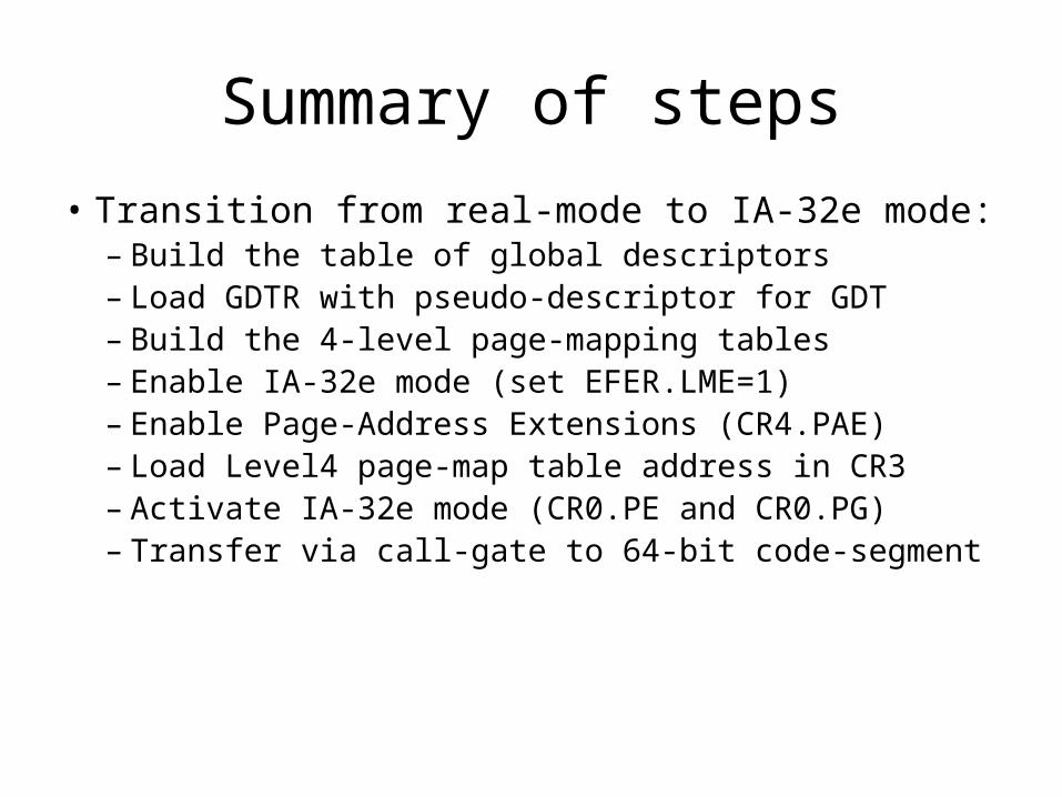
Summary of steps
• Transition from real-mode to IA-32e mode:– Build the table of global descriptors – Load GDTR with pseudo-descriptor for GDT– Build the 4-level page-mapping tables– Enable IA-32e mode (set EFER.LME=1)– Enable Page-Address Extensions (CR4.PAE)– Load Level4 page-map table address in CR3– Activate IA-32e mode (CR0.PE and CR0.PG)– Transfer via call-gate to 64-bit code-segment
Notes on the transition
• Code-segment must be “identity-mapped”
• Interrupts have to be temporarily disabled
• All memory-addressing in 64-bit mode via CS, SS, DS or ES uses 0 as base-address (and checking of segment-limits is omitted)
For a return to ‘real-mode’
• Processor must enter 16-bit code-segment in ‘compatibility-mode’ via indirect far jump– Load segment-registers DS, ES, and SS with
‘writable’ 16-bit segment-selectors (64K-limit)– Code-segment has to be “identity-mapped”– Deactivate IA-32e mode by clearing PG-bit– Leave ‘protected-mode’ by clearing PE-bit– Reload registers CS and SS with real-mode
segment-addresses before enabling interrupts
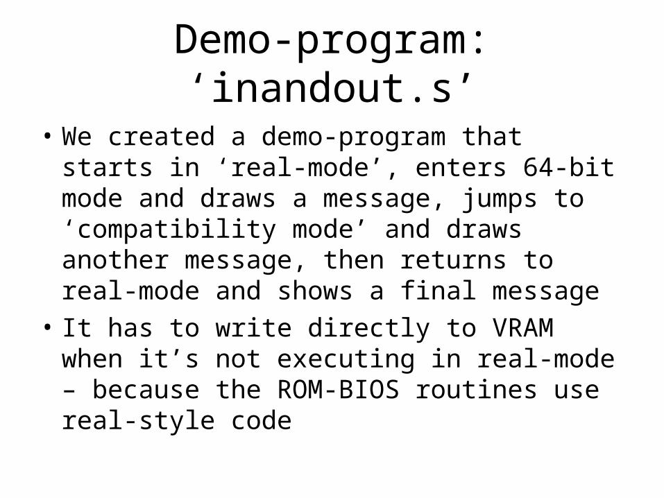
Demo-program: ‘inandout.s’
• We created a demo-program that starts in ‘real-mode’, enters 64-bit mode and draws a message, jumps to ‘compatibility mode’ and draws another message, then returns to real-mode and shows a final message
• It has to write directly to VRAM when it’s not executing in real-mode – because the ROM-BIOS routines use real-style code
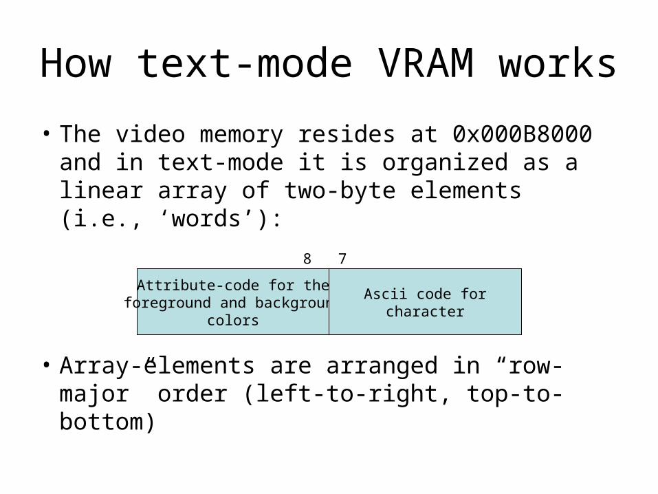
How text-mode VRAM works
• The video memory resides at 0x000B8000 and in text-mode it is organized as a linear array of two-byte elements (i.e., ‘words’):
• Array-elements are arranged in “row-major” order (left-to-right, top-to-bottom)
Attribute-code for theforeground and background
colors
Ascii code forcharacter
15 8 7 0
Blue1
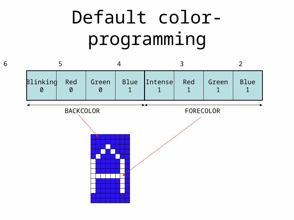
Default color-programming
Intense1
Red1
Blue1
Green1
Red0
Green0
Blinking0
FORECOLORBACKCOLOR
7 6 5 4 3 2 1 0
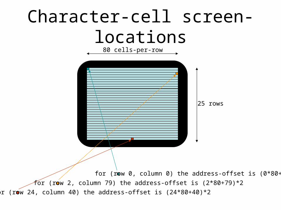
Character-cell screen-locations80 cells-per-row
25 rows
for (row 0, column 0) the address-offset is (0*80+0)*2
for (row 2, column 79) the address-offset is (2*80+79)*2
for (row 24, column 40) the address-offset is (24*80+40)*2
In-class exercise #1
• Can you modify the message-colors used in our ‘inandout.s’ demo-program so that:– the first message is bright-red against white– the second message is brown against cyan – The final message is magenta against black
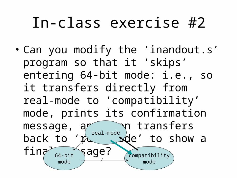
In-class exercise #2
• Can you modify the ‘inandout.s’ program so that it ‘skips’ entering 64-bit mode: i.e., so it transfers directly from real-mode to ‘compatibility’ mode, prints its confirmation message, and then transfers back to ‘real-mode’ to show a final message?
64-bitmode
real-mode
compatibilitymode