Embed Size (px)
Citation preview
Advanced Thermal Hydronics, 2004 DOC #HYDKNV3HL
260 N. Elm St.
Westfield, MA 01085
05/03/17 1
Advanced Thermal Hydronics KN Series H-NET V3 Control Firmware Revision Sheet
3 - May - 2017 Release
Control Firmware Revision 2.58-2.59
1. Added a Low Fire Shutdown on all Heat Demand inputs for better reliability. When a Call for heat
has ended, and if the firing rate was over 50%, the boiler will drop to low fire and run for one minute
before shutting off.
2. Corrected an issue when direct modulating using the 4-20mA input. Display values did not
accurately track the control signal.
LCD Touch Display Firmware Revision 1.2-R10
1. Made several data status and reliability improvements to HeatNet Online.
2. Enhanced the SNTP (Network Time) client to improve synchronization speed and provide additional
status messages.
3. Fixed an issue that caused the SNTP client to continuously emit a “failed” message (shows up in the
HeatNet Online Status Monitor), while waiting for a response when synchronization has already
failed.
4. Fixed an issue that could sometimes cause HeatNet Online to stop transmitting data. This issue
ONLY affected version 1.2-R9.
5. Added support for the new “Low Fire Shutdown” status code.
15 - March - 2017 Release
Control Firmware Revision 2.55 - 2.57
1. Added support for a flash chip component designator: U25. The old component went End of Life
and new drivers were written to allow operation of the new component. U25 is used as an
intermediary storage location when updating firmware.
2. Corrected an issue when the personality profile was loaded. The display would indicate 5% at low
fire when in Calibrate, though the boiler would run correctly.
3. Enhanced the bootloader for loading firmware. The percentage loaded is now displayed when
loading firmware. The bootloader can only be updated at the factory. All product shipped from this
date will have it loaded.
4. Due to the new flash chip (U25) on the HeatNet control, older versions of firmware cannot be
loaded. Older versions of firmware cannot read or write the new flash chip.
5. Corrected a display issue while in calibrate. The Calibration Screen would show the Modulation at
the Maximum % when the Minimum % or Ignition % was selected.
LCD Touch Display Firmware Revision 1.2-R9
6. Updated the HeatNet Online Status file format with Windows compatible line breaks so it is properly
displayed in simple text editors like Notepad.
7. Improved the SNTP client by making it more resilient to network and time server issues.
8. Fixed a minor issue with restoring settings from USB on control firmware versions < 2.54. A file
read error was sometimes displayed even when there were no errors.
9. Added enumerations for “Pump Change” and “Summer Pump Jog” log entries.
10. Added “PVC” notation to the version on the Splash Screen and the Master/Boiler dialogs when PVC
firmware is detected on the HeatNet Control.
11. Fixed an issue with setting the Lead Boiler. The enumerated selections were incorrect:
Incorrect (old) Correct (new)
Advanced Thermal Hydronics, 2004 DOC #HYDKNV3HL
260 N. Elm St.
Westfield, MA 01085
05/03/17 2
Master (0) Auto (0)
Member 2 (1) Master (1)
… …
Member 16 (15) Member 16 (16)
12. Added support for the new flash chips being used on the HeatNet Control.
13. Added support for the enhanced bootloader added to the HeatNet Control. During the programming
stage of a control firmware update, the actual progress percent is now displayed instead of an
estimated time remaining.
14. Fixed an issue that would occasionally cause an “Out of Memory” message.
19 - DEC - 2016 Release
Control Firmware Revision 2.51 - 2.54
1. Corrected an issue where a saved setting was updated too frequently when using an LCD color
display. The result of this was a damaged storage block in the EEPROM saved settings memory. The
EEPROM has a limited amount of times that it can be written to before being damaged. When the
saved byte’s cells were damaged, the result was that it took out the whole block of 256 bytes
associated with it. This resulted in adjacent save locations being damaged.
With this release, the 256 byte block that is affected is marked bad and the saved settings are moved
to an adjacent free block.
The damaged save locations could cause errant operation. These locations are not damaged when
using the 4-line green Vacuum Florescent display and operation will be normal.
The affected saved settings were:
Heat Exchanger Return Water Temperature
Return Threshold Temp (takes a boiler offline if the Return temp is less than above temp)
DHW Max Runtime
DHW Holdoff Time (used to prevent the boiler from staying too long in DHW mode)
Force a Firmware file to be loaded ( causes No Communications with the LCD)
2. Removed support for the KB Variable frequency drive at 110Hz.
LCD Touch Display Firmware Revision 1.2-R8
No Changes
30 - Nov - 2016 Release
Control Firmware Revision 2.50A
No Changes.
LCD Touch Display Firmware Revision 1.2-R8
1. Fixed issue with SNTP (Network Time) that caused incorrect time on the Display and HeatNet
control when HeatNet Online was enabled.
2. Added improved DHW operation display.
Advanced Thermal Hydronics, 2004 DOC #HYDKNV3HL
260 N. Elm St.
Westfield, MA 01085
05/03/17 3
3. Added Data Capture feature which can be used to periodically save a predefined set of temperatures
and operational data to a USB drive. The data is saved as comma separated values (CSV) so it can
be viewed and analyzed in any application that supports that format.
16 - Nov - 2016 Release
Control Firmware Revision 2.50A
1. Adjusted the frequency of the PWM to 110Hz when the blower is set to VFD. This is to
accommodate the older KB VFD for backwards compatibility. It was set for 120 Hz.
4 - Nov - 2016 Release
Control Firmware Revision 2.50
1. Bumped the Firmware to V2.50 for this formal release
2. Disabled the Auto Detection feature of the OA sensor to prevent false detection.
3. Fixed issue with saving the Number of System Pumps and the System Pump Rotation on LCD
Display. Previously it could take up to an hour before they were saved.
10 - Oct - 2016 Release
Control Firmware Revision 2.43-2.44
1. Added a DHW Override Mode with Sensor as a supplement to DHW Mode 4, which will now be
designated as Mode 4B. This mode was originally in the HeatNet Version 2 board firmware, but was
not migrated over to Version 3.
This mode is only available on the Master boiler since it’s purpose is to override the system
setpoint. In this mode the space heating setpoint (Header) is overridden with the DHW setpoint, and
the DHW temperature is maintained at the DHW sensor using the DHW pump. The Master boiler
will only control the DHW pump and allow all boilers to fire to maintain the DHW setpoint. The OA
OVR input and the Heat Demand input must be closed to enable this mode. If either of these inputs
are opened, the mode will be stopped.
All boilers are started and stopped using the space heating Modular Boiler Settings. The
Modular Boiler DHW tab is not available.
In prior versions, Method 2 was only allowed in this application. This method required setting
the Distributed Control: Master Type: to Combo along with the DHW (Boiler Mode): set to Combo
on each boiler used for DHW heating. Using this mode allowed a DHW failsafe mode and pump
redundancy. The limitation in this mode was that all DHW pumps needed to be wired in parallel. If
the Master was the only boiler allowed to control the DHW pump, all other boilers needed to have
their respective DHW (Boiler Mode): set to AUTO. This limited the system to only one boiler
controlling the DHW heating load and no failsafe operation.
With this release and the LCD Touch panel firmware release, the Master will only show a
showerhead indicating the system is running in DHW override. Member boilers will not show the
showerhead since they are unaware of the task the Master is performing.
Settings: Distributed Control: Master Type: AUTO
DHW( Boiler Mode): AUTO
DHW: Use Sensor
2. Added a DHW pump stays on feature which can be used with the DHW Override Mode with sensor.
3. Added the ability to disable the DHW Max Runtime by setting it to 0.
Advanced Thermal Hydronics, 2004 DOC #HYDKNV3HL
260 N. Elm St.
Westfield, MA 01085
05/03/17 4
LCD Touch Display Firmware Revision 1.2-R7
15. Added support for new DHW mode as outline above.
24 – August - 2016 Release
Control Firmware Revision 2.41-2.42
1. Fixed an issue that could cause control to reboot when a Modbus “Read Device Identification”
request is sent by the BMS.
2. If the Master Pump/Valve Remains on is set to ON or Always Enabled is set to ON (in the local
pump settings), the boiler will always look for flow. With this release and in this case, the flow is not
monitored when there is no call for heat.
LCD Touch Display Firmware Revision 1.2-R6
1. Added support for new products.
28 – June - 2016 Release
Control Firmware Revision 2.39
No Changes.
LCD Touch Display Firmware Revision 1.2-R5
1. Added HeatNet Online functionality.
5 – May - 2016 Release
Control Firmware Revision 2.39
No Changes.
LCD Touch Display Firmware Revision 1.2-R4
1. Added Maximum DHW Runtime Exceeded and LCD Power Reset log entries.
2. Added improved DHW operational status on master and member boilers.
3. Added a button to update the Display Firmware on the "No Communications Screen".
4. Added ability to detect if the display is booting from on board memory (EMMC) instead of the SD
card. This is required to properly handle display switching on products with multiple heat
exchangers.
5. Changed minimum DHW hold off time from 0 to 1 minute (60 seconds).
6. Fixed an issue with Open File Dialog which prevented valid matching files, but with different
character casing from showing up in the file list. It is now case insensitive.
7. Fixed an issue with boiler buttons on the main screen. The “too hot” indicator was being displayed
when the operator interlock was open.
3 – May - 2016 Release
Control Firmware Revision 2.38-2.39
Advanced Thermal Hydronics, 2004 DOC #HYDKNV3HL
260 N. Elm St.
Westfield, MA 01085
05/03/17 5
1. The firmware file name for version 2.37 inadvertently had the file extension “.HEX” set to
uppercase. The current LCD display firmware only supports lower case file extensions. So, in order
to install V2.37, the “.hex” extension would need to be changed to lowercase.
2. An issue occurs after the last release, where the Local Pump will remain on if the Main valve never
opens and an extreme short cycle occurs. Once the boiler fires, the Local Pump resumes normal
operation. This has been corrected to not allow the Local Pump to remain on.
3. If the HeatNet control has a previous companies/ product range firmware installed, it can cause the
other companies product to display non-released products. This has been corrected.
4. Added the ability of a Member boiler to use the DHW MOD-MAX: RELEASE MOD MAX feature
to limit the DHW modes firing rates to the MOD MAX value.
5. Changed the Default DHW timeout to 2 hours from 1 hour, and the Holdoff (retry) to 30 minutes
(was LOCKOUT). This allows the DHW call for heat to occur for a maximum time of 2 hours
before shutting down and sets the wait time before firing in DHW again to 30 minutes.
6. Also, Limited the DHW Holdoff time to 1 minute minimum from 0 minutes due to possible race
conditions.
7. Corrected an LCD Display issue when displaying DHW Modulation.
8. Limited the ADAPTIVE MOD: DELAY RELEASE: minimum and default time to 5 Seconds. The
minimum was 0 seconds. If 0 seconds are needed, use the ORIG KN setting rather than ADAPTIVE
under MOD MODE.
LCD Touch Display Firmware Revision 1.2-R3
No Changes
13– APR - 2016 Release
Control Firmware Revision 2.36-2.37
1. An issue occurs after the last release where the DHW OR OVR input when toggled in DHW
COMBO and Master Boiler in MASTER TYPE: COMBO, fails to start the next DHW cycle. The
Hold-off timer for the Maximum Runtime of the DHW fails to reset when in LOCKOUT. This
change ensures that the Lockout setting is cleared when the OR OVR is toggled.
2. Fixed an issue when using the VFD pump signal and the Local Pump Always Enabled feature. Prior
to this release, the local pump’s VFD modulation signal would hunt between a low speed and a high
speed when post purging. This has been corrected to provide a stable high speed pump VFD signal at
the Max VFD setting.
3. Issue with detecting a missing/open Stack sensor. If a Stack Sensor opens or is removed when it was
installed, the open sensor warning may not occur due to threshold sensing. The threshold has been
increased to allow greater detection.
4. Fixed issues with display modulation during modulation delay and in DHW operation.
5. Fixed issues with stack temperature when a TypeZ sensor is used. The temperature need to be
divided by 100.
6. Fixed issues saving Local Pump Always Enabled and Local Pump Delta Temp Enabled.
7. Fixed issues saving System Pump Always Enabled and Override Enabled in Warm Weather
Shutdown.
LCD Touch Display Firmware Revision 1.2-R3
No Changes
26 – Jan - 2016 Release
Control Firmware Revision 2.35
1. An issue with KN6 & KN10s exceeding the Max tach value of 8800 rpms during post purge.. A tach
fault occurred when the Max VFD was set to a value that causes the blower to exceed 8800 rpms.
Advanced Thermal Hydronics, 2004 DOC #HYDKNV3HL
260 N. Elm St.
Westfield, MA 01085
05/03/17 6
The post purge speed is now fixed at 80% signal and no longer linked to the Max VFD setting in
calibration.
LCD Touch Display Firmware Revision 1.2-R3
No Changes
19 – Jan - 2016 Release
Control Firmware Revision 2.33 - 2.34
No Changes.
LCD Touch Display Firmware Revision 1.2-R3
1. Added improved support for the LCD Boost interface card when loading control firmware to prevent
unexpected resets.
2. Made improvements to the method used for network restarts to help resolve issues when a network
cable is not connected.
3. Fixed issues with editing temperature settings in Celsius.
4. Fixed an issue that occurred when the Display Units (English, Metric) was changed. The change
inadvertently reset the following settings: Analog (4-20ma, 0-10V) Channel Priority, Firing Mode,
Damper Type, Damper Enable, and Alarm Input/Silence.
5. Fixed an issue that occurred when setting the Heat Exchanger Delta Temperature. The upper limit
was incorrectly calculated which limited the ability to increase the value to the correct maximum.
6. Modified boiler buttons so that the modulation percent is only displayed when it is non-zero.
7. In some cases, when control firmware was upgraded from a different product line, a KN2 or KN4
was selected even though those products are not currently supported by this hardware. The product
can now be changed to a currently supported KN Series boiler (KN6, KN10, ...).
8 – Jan - 2016 Release
Control Firmware Revision 2.33 - 2.34
1. Removed the Heat Exchanger: Temperature Disable feature functionality. V2.33
2. Support for the LCD Boost interface card to allow automatic reset of the LCD after 1 minute if the
LCD display has locked up or stopped transmitting data to the HeatNet control. V2.33
3. Increased the wait time for the LCD Boost Interface to 2 minutes (loss of communications) to ensure
a reset does not occur when flashing updates. V2.34
4. Added a timeout setting for the Domestic Hot Water modes. This timeout value can be set in
SETUP: DOMESTIC HOT WATER: MAX RUNTIME: The DHW heating can be set to timeout up
to (2) hours. The default time is (1) hour of continuous DHW heating. Once this time has been
exceeded, a second timer is activated, called the HOLDOFF timer. It is located at SETUP:
DOMESTIC HOT WATER: HOLDOFF. It can be used to hold off a call for the next DHW cycle, or
Lockout after the Max Runtime has been exceeded. The HOLDOFF timer also has a maximum time
of (2) hours and a default of LOCKOUT. V2.33
18 – Dec - 2015 Release
LCD Touch Display Firmware Revision 1.2-R2
1. Added support for DHW Max Runtime and DHW Holdoff Time.
17 – Dec - 2015 Release
Control Firmware Revision 2.33
Advanced Thermal Hydronics, 2004 DOC #HYDKNV3HL
260 N. Elm St.
Westfield, MA 01085
05/03/17 7
1. Removed the Heat Exchanger: Temperature Disable feature functionality.
LCD Touch Display Firmware Revision 1.2-R1
1. Added support for saving the log file to a comma separated values (CSV) file on a USB drive.
2. Added support for units with multiple Heat Exchangers. The display input can be switched
(multiplexed) between each control.
3. Fixed several minor issues that sometimes occur when the control firmware has a product selected
which the display firmware does not yet support.
4. Fixed an issue with the document viewer which caused the cursor to not be restored when a long
operation was cancelled.
5. Added “Sync” mode to Baseload Start Mode and Baseload Stop Mode on firmware versions greater
than 2.31.
6. Added support for dynamic Max Water Setpoint, Max DHW Setpoint, and Max. System Operating
Limit.
7. Added support for changing Network Settings (IPv4 Address, Subnet Mask, etc.)
8. Improved the modulation value displayed on the status line. If the boiler is “running”, but the
modulation is <= 1, “Running” is displayed instead of “Running 0%”. This typically occurs during
the boilers main valve proving time.
7 – Oct -2015 Release
Control Firmware Revision 2.30 - 2.32
1. Improved filtering of temperature sensors to stabilize jumping temperatures with long sensor wire
runs.
2. Increased the boiler starting time before the High/Low delta protection is engaged to 5 minutes. This
will allow the delta temperature to increase sufficiently to exit the delta protection algorithm if
proper flow is present.
3. Added the detection of the tach signal when using the Ametek blower or the VFD. If an incorrect
setup is detected, as when a VFD is selected vs an Ametek blower or the other way around.
“BLOWER, RPM FAULT” will now be displayed if a Tach signal is present or not, and is
dependent on the configuration. The tach signal now has to be present for the boiler to fire when an
Ametek drive is used, or not present when a VFD is used. This is a lockout condition.
LCD Touch Display Firmware Revision 1.1-R5
1. Added display watchdog support for the newest and future OS releases.
2. Updated all logo and splash screen images to the new HeatNet logo.
LCD Touch Display Firmware Revision 1.1-R4
1. Added support for Heat Exchanger Max. Runtime setting, log entries, and status.
2. Enabled watchdog timer on the display.
3. Fixed an issue that prevented Load Factory Calibration from working properly.
20 – July -2015 Release
Control Firmware Revision 2.30
1. Fixed an issue with the dual fuel relay caused by the prior release.
2. Removed the auto detection of the stack sensor.
LCD Touch Display Firmware Revision 1.1-R4
Advanced Thermal Hydronics, 2004 DOC #HYDKNV3HL
260 N. Elm St.
Westfield, MA 01085
05/03/17 8
No Changes.
3 – June -2015 Release
Control Firmware Revision 2.21 - 2.22
No Changes.
LCD Touch Display Firmware Revision 1.1-R4
1. Fixed a bug that prevented the “Load Factory Calibration” menu selection from working properly.
2. Fixed a bug that prevented the “Factory Reset” menu selection from working properly.
3. Added support for Maximum Runtime in the Heat Exchanger menu.
4. Enabled watchdog reset to help prevent rare system lockups on installations with severe electrical
noise.
27 – May -2015 Release
Control Firmware Revision 2.21 - 2.22
1. Increased the fan Post Purge speed to aide in drying the heat exchanger pins. The fan Post Purge will
run at the Max VFD setting. It can be also used with the Extended Post Purge speed in the Heat
Exchanger menu to extend the Post Purge time.
2. Added a Maximum Runtime setting, SETUP: AUX FUNCTIONS: HEAT EXCHANGER: MAX
RUNTIME. This setting is adjustable from 1 – 24 hours in hour increments. The 24 hour maximum
is determined by the UV scanner requirements, and that it be tested every 24 hours of continuous
runtime. Example: If set to 6 hours, the boiler will shut down after 6 hours of continuous runtime. It
is not cumulative between starts. After its post purge has completed, the boiler will be allowed to
restart.
The Message, “MAX RUNTIME LIMIT” will be displayed on the vacuum fluorescent’s main run
screen. The Log will also display this message when the event has occurred.
This feature may be used in low temperature systems where condensation in the heat exchanger is
high due to continuously running of the boiler in low fire. This setting allows for the heat exchanger
pin condensates to be purged periodically to aide in the removal of flue gas contaminants.
LCD Touch Display Firmware Revision 1.1-R3
The Max Runtime menu is not available with this release on the LCD display. If it is required, a vacuum
fluorescent display may be plugged in and the Max Runtime values set. The LCD display may then be
plugged back in.
30-Mar-2015 Release
Control Firmware Revision 2.19 - 2.20
No Changes.
LCD Touch Display Firmware Revision 1.1-R3
1. Fixed an issue with changing the Master Type (Distributed Control) on DHW member boilers.
2. Added better descriptions (include input location i.e. J12B) for Interlock status line messages.
27-Mar-2015 Release
Control Firmware Revision 2.19 - 2.20
Advanced Thermal Hydronics, 2004 DOC #HYDKNV3HL
260 N. Elm St.
Westfield, MA 01085
05/03/17 9
1. This revision supports the V1.6 HeatNet control. The Hardware revision 1.6 is different from prior
versions in that it has greater protection from static and high voltage discharge. The G terminal is
also protected from 24vac on the communication line. It can be identified by a green power LED
near the 24VAC connector J14 and component VAR1.
2. Removed the running restriction when calling a Base Load boiler from a Member boiler. The
Member boiler does not need to be firing in order to call a Base Load boiler. Provisions on the
Base Load boiler should be checked to allow a system pump to run and any dampers to
open. Failsafe using the Base Load boiler from the Member is automatic. Whenever the Member fails,
the Base Load boiler will be enabled as long as the Member can do so.
The Master boiler still requires a heat demand input in order to control a Base Load boiler
connected to it. Though, the Master boiler does not need to be running. This is to ensure that the
system pump and damper will be enabled for the system. The System pump and Damper control
are the main reasons to connect the Base Load boiler to the Master.
Failsafe on the Master boiler will occur if there is a Heat Demand input present, there are no
available boilers to fire, and the Master has failed.
24-Feb-2015 Release
Control Firmware Revision 2.18
No Changes.
LCD Touch Display Firmware Revision 1.1-R2
1. Fixed an issue with saving files to the USB Drive. If the drive was removed to quickly, the file
would be lost.
2. Made communications between the Display and the HeatNet Control more robust.
19-Feb-2015 Release
Control Firmware Revision 2.18
1. Fixed an issue with the boiler modulation values available on a BMS (Modbus, BACnet,
LonWorks). The modulation value was not returning to zero when the boiler stopped running.
LCD Touch Display Firmware Revision 1.1-R1
No Changes.
6-Feb-2015 Release
Control Firmware Revision 2.17
1. Fixed an issue with the operating setpoint displayed on the member boiler. The member was not
correctly displaying the master (system) setpoint when being controlled by the master.
LCD Touch Display Firmware Revision 1.1-R1
No Changes.
23-Jan-2015 Release
Control Firmware Revision 2.14 - 2.16
Advanced Thermal Hydronics, 2004 DOC #HYDKNV3HL
260 N. Elm St.
Westfield, MA 01085
05/03/17 10
1. A condition exists when controlling Variable Speed Local Pumps with the Delta T protection
algorithm active. The output on J4.1 & .4 are mapped to the called for firing rate even though the
real firing rate is less when the Delta T algorithm is active. This change maps the variable speed
pump signal to the real firing rate. 2. Added the Russian build. 3. Fixed an issue with the “SETUP: PUMP OPTIONS: LOCAL PUMP: ALWAYS ENABLED” set
to ON. When this feature is used on the Master boiler the boiler may not start after completing a
cycle. This has been corrected with this release. 4. Fixed an issue where the Low Delta message is displayed when the boiler is off. The Delta Temp
message will only be displayed when the boiler is running.
LCD Touch Display Firmware Revision 1.1-R1
No Changes.
16-Dec-2014 Release
Control Firmware Revision 2.13
1. The control no longer locks out when a DHW sensor fault occurs. If the DHW sensor temporarily
faults the DHW Heating status is restored. Also, if the boiler is operating in Combo mode and the
DHW sensor faults, space heating is still available.
2. Changed the default setting of the DHW SHARING option. Prior to this change, its default setting
was set to OFF. The OFF setting would not allow DHW heating to occur as long as the boiler was
running in space heating mode. Once it finished space heating, DHW heating would start. The
default setting is now set to CYCLE which is a DHW priority mode. If the boiler is running in
space heating a DHW call for heat will result in the boiler cycling off and then restarting in DHW
heating mode.
LCD Touch Display Firmware Revision 1.1-R1
No Changes.
10-Dec-2014 Release
Control Firmware Revision 2.12
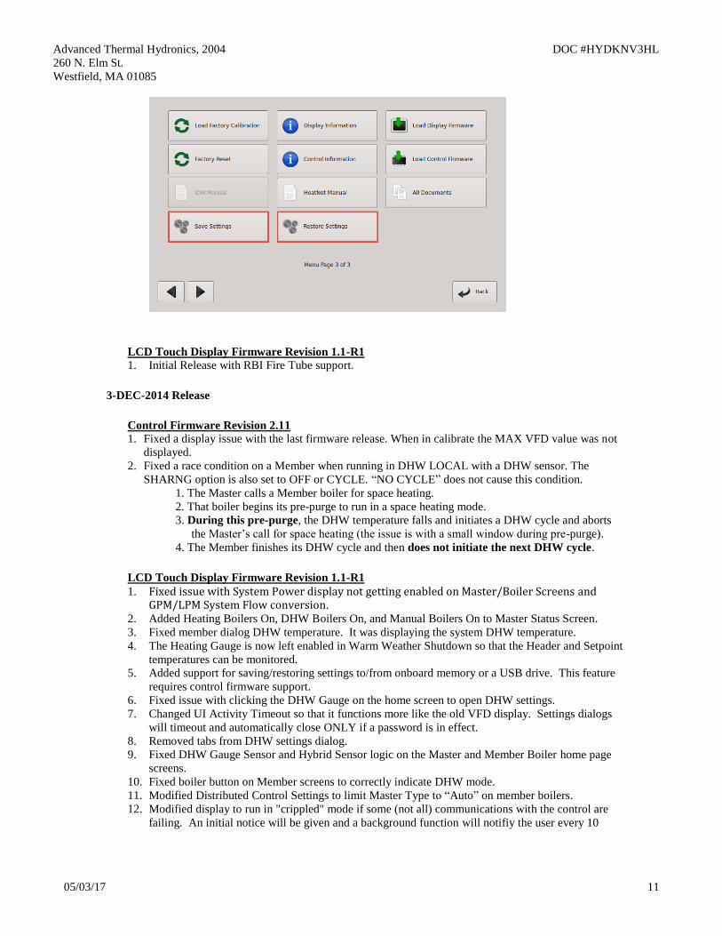
1. Firmware support for the Color LCD display to allow saving and restoring setup files to a flash
drive. Setups can now be done remotely, placed on a flash drive, and then uploaded to the control.
This also requires that LCD Touch Display Firmware Revision 1.1-R1 be installed.
The Save/Restore menu buttons are located on menu page 3.
Advanced Thermal Hydronics, 2004 DOC #HYDKNV3HL
260 N. Elm St.
Westfield, MA 01085
05/03/17 11
LCD Touch Display Firmware Revision 1.1-R1
1. Initial Release with RBI Fire Tube support.
3-DEC-2014 Release
Control Firmware Revision 2.11
1. Fixed a display issue with the last firmware release. When in calibrate the MAX VFD value was not
displayed.
2. Fixed a race condition on a Member when running in DHW LOCAL with a DHW sensor. The
SHARNG option is also set to OFF or CYCLE. “NO CYCLE” does not cause this condition.
1. The Master calls a Member boiler for space heating.
2. That boiler begins its pre-purge to run in a space heating mode.
3. During this pre-purge, the DHW temperature falls and initiates a DHW cycle and aborts
the Master’s call for space heating (the issue is with a small window during pre-purge).
4. The Member finishes its DHW cycle and then does not initiate the next DHW cycle.
LCD Touch Display Firmware Revision 1.1-R1
1. Fixed issue with System Power display not getting enabled on Master/Boiler Screens and GPM/LPM System Flow conversion.
2. Added Heating Boilers On, DHW Boilers On, and Manual Boilers On to Master Status Screen.
3. Fixed member dialog DHW temperature. It was displaying the system DHW temperature.
4. The Heating Gauge is now left enabled in Warm Weather Shutdown so that the Header and Setpoint
temperatures can be monitored.
5. Added support for saving/restoring settings to/from onboard memory or a USB drive. This feature
requires control firmware support.
6. Fixed issue with clicking the DHW Gauge on the home screen to open DHW settings.
7. Changed UI Activity Timeout so that it functions more like the old VFD display. Settings dialogs
will timeout and automatically close ONLY if a password is in effect.
8. Removed tabs from DHW settings dialog.
9. Fixed DHW Gauge Sensor and Hybrid Sensor logic on the Master and Member Boiler home page
screens.
10. Fixed boiler button on Member screens to correctly indicate DHW mode.
11. Modified Distributed Control Settings to limit Master Type to “Auto” on member boilers.
12. Modified display to run in "crippled" mode if some (not all) communications with the control are
failing. An initial notice will be given and a background function will notifiy the user every 10
Advanced Thermal Hydronics, 2004 DOC #HYDKNV3HL
260 N. Elm St.
Westfield, MA 01085
05/03/17 12
minutes unless an Firmware or Display update is in progress. This makes it easier to get the boiler
up and running even if a display or control firmware update is needed.
13. Added support for better boiler product identification of member boilers if the data is available on
the master. This requires control firmware support.
14. Added support for member boiler stack temperature if the data is available on the master. This
requires control firmware support.
15. Changed “Outside Air” to “Outdoor Air” for all Outdoor Air Reset related text.
21-Nov-2014 Release
Control Firmware Revision 2.10
(no changes)
LCD Touch Display Firmware Revision 1.0-R4
1. Fixed an issue with the DHW gauge on the Home screen. It was not getting enabled properly on
member boilers.
LCD Touch Display Firmware Revision 1.0-R3
1. Fixed an issue with the DHW gauge on the Home screen. It was not getting enabled properly in all
DHW operating modes and conditions.
2. In “Master Type” (Settings – Distributed Control), “Mixed” has been renamed to “Combination”.
3. In DHW “Boiler Mode” (Settings – Domestic Hot Water), “Mixed” has been renamed to
“Combination”.
LCD Touch Display Firmware Revision 1.0-R2
1. Fixed an issue that prevented changing the “HeatNet Communications Lost” Failsafe mode (in
Settings – Failsafe Modes).
LCD Touch Display Firmware Revision 1.0-R1
1. Initial Release.
Revision 2.10 11- Nov-2014 Release
1. Fixed a flashing message that blinked too fast in the STATUS * screen.
2. Fixed a display issue with the DHW modulation % in the DHW graph. The modulation used by the
boiler was correct, but the display % added a scaling offset. This offset was removed. Also, on the
DHW screen on the Master boiler, the % modulation always is for the system DHW Modulation. If
the DHW modulation delay is in effect on the Master or Member, the called for Modulation is
displayed.
3. Added the Adaptive Mode to the DHW. This mode was not available in the prior release. Now, the
DHW will use the ADAPTIVE MOD space heating settings when firing DHW boilers.
4. Fixed the DHW Modulation delay to be 60 minutes rather than 4 minutes. This value needs to be set
on each boiler. It is not a global value used by the Master.
5. Added the ability to use the Mod Max value as a limit clamp on DHW boilers. If the ADVANCED
SETUP: MODULAR BOILER SET: DHW HEATING: MOD MAX _ LAST FIRE: RELEASE
MOD MAX is set to YES, then when all boilers are firing, the clamp is released and all boilers are
allowed to fire to 100%. If the RELEASE MOD MAX is set to NO, the clamp will remain in effect
regardless if all boilers are firing.
Revision 2.05-2.06 Nov-2014 Release
Advanced Thermal Hydronics, 2004 DOC #HYDKNV3HL
260 N. Elm St.
Westfield, MA 01085
05/03/17 13
1. There exists confusion with the DHW BOILER? MIXED setting and the DISTRIBUTED CTRL:
MASTER TYPE: MIXED setting, with the FIRING MODE: MODE: MIXED setting. The setting
for DHW and MASTER TYPE will now be named COMBO, for Combination DHW and Space
heating. FIRING MODE: MODE:MIXED will remain the same.
2. Removed the repeated Fault during retries of the blower. Now, when the blower has failed and a
retry is initiated, HEAT:WAIT is displayed. After 3 attempts the AIR SWITCH (BLOWER) will be
displayed along with the Alarm relay and Fault condition.
Revision 2.04-Sept-2014 Release
1. When using the Combo DHW mode, and keeping the local pump on, a race condition with proving
flow existed. This configuration would sometimes cause a flow fault due to the local pump not
starting. This has been corrected with this release.
Revision 2.02- 2.03 5-Sept-2014 Release
1. Low OA Set at Modbus address 40009 fails to save properly when written from
Modbus/BACnet/LonWorks. This version corrects this.
2. When in Warm Weather Shutdown, using the DHW LOCAL PUMP SHUTS OFF: set to YES, and
LOCAL PUMP –PUMP VALVE OPTION: MASTER PUMP /VALVE REMAINS ON: set to ON
the local pump relay toggles off and on. The local pump with this release remains ON in this
situation.
3. When using the DHW modes with a mixed master, the System DHW Setpoint is incorrectly
displayed on the Member boiler. This has been corrected. As a Note: The Member boilers DHW
band does not reflect the System DHW Setpoint. It is only used to display the Local DHW setpoint
and setpoint band. The System DHW Setpoint on the Member is for information only, since the
Master direct modulates the Member to meet its DHW Setpoint.
The Master only displays the Space Heating Setpoint, it does not alternate between displaying
System DHW Setpoint and System Setpoint.
Revision 2.00 1-July-2014 Release
1. Full firmware support release for the Color LCD touch display.
Revision 1.93 - 1.99 15-June-2014 Pre-Release
1. Added the Hybrid mode 5A/5B for DHW. This mode allows a thermostat from a tank to enable
DHW heating and then monitor a designated sensor to control tank temperature.
2. Added the ability to save and restore configuration settings. This menu item is available in
ADVANCED SETUP:LOAD DEFAULTS: CONFIG ?
3. Fixed an issue that occurs when PREDICT START is used. If the temperature is falling too fast, a
boiler will start in the heating band. If it is still falling before enough energy is introduced, another
boiler would start immediately once the temperature dropped below the band. This change keeps the
ADD BOILER delay time active in the band for a pre-started boiler.
Advanced Thermal Hydronics, 2004 DOC #HYDKNV3HL
260 N. Elm St.
Westfield, MA 01085
05/03/17 14
4. Added a software filter for Outside Air temperatures that are unstable or have electrical noise on
their respective wires. This filter automatically stabilizes most OA temperature signals using
unshielded wire or noisy sensors. OA sensors using the Outdoor Reset function that are noisy will
cause the heating band to jump. The jumping band would cause boilers to fire or shut off when the
target temperature sensor is near the lower or upper edge of the heating band.
Revision 1.89 - 1.92 20-MAY-2014 Pre-Release
1. Added the ability to optionally control the contactor to the Ametek blower. If this feature is used, the
Stage 4 relay will open and close to engage the blower contactor. At power-up, the contactor will be
engaged 7 seconds after all other components have powered up. This is to minimize inrush.
In the event the blower stalls or locks out, the power to the contactor will be cycled. This will occur
(3) times every 10 minutes before the boiler locks out. This should aide in nuisance lockouts of the
blower and a maintenance call to reset the boiler power.
This feature is always enabled, but needs to be wired to function. The Hot wire from the contactor’s
enable should be removed and wired to one side of the Stage 4 relay J12A.1. A new 18guage wire
should then be run from J12A.2 of the Stage 4 relay contact to the contactor’s enable that was
removed.
2. Added protection for a short heat Demand cycle. If any heat demand cycle including the OR OVR
input is cycled, with the call occurring in less than 8 seconds, the pre-purge will continue. In prior
releases, the pre-purge would stop immediately and enter post-purge. This may not have given
enough time for the Ametek blower to start causing an over current condition.
3. Fixed an issue with the DHW LOCAL PUMP OFF/LOCAL DELAY menu. The selection only
allowed the down arrow key to work.
Revision 1.88 2-APRIL-2014 Pre-Release
1. Limited the SETUP:AUX FUNCTIONS:HEAT EXCHANGER:TEMP < 140F setting to go no
lower than 135F.
2. Fixed an issue with saving the MIN OFF TIME. Values larger than 4 minutes were not saved.
Revision 1.87 1-APRIL-2014 Pre-Release
1. Increased the reset temperature of the upper and lower control limit (Add and Shed boiler delay) of
the heating band to 1.5 degrees. This change is to minimize the effect of boilers shutting off or
starting due to temperatures jumping in and out of the heating band.
2. Increased the maximum ADD BOILER delay time from 15 minutes to 1 hour due to requests.
3. Added the ability for a boiler to take itself offline from HeatNet when the return water temperature
is below a threshold. This feature would primarily be used to keep non condensing boilers from
firing in a condensing situation. It may be also used with the priority 1 & 2 modes to keep only
condensing boilers running when return temperatures are low.
If the boiler is isolated by a pump/valve, a HeatNet V3 board can be used as a Master boiler to
supply the return temperature. The V3 board has the ability to measure the system return temp and
send it to each boiler via the HeatNet network. A version 2 board running on a non-condensing
boiler can then use it to view the system return temperature and make itself, not available to fire
Advanced Thermal Hydronics, 2004 DOC #HYDKNV3HL
260 N. Elm St.
Westfield, MA 01085
05/03/17 15
by HeatNet. While the boiler is in this “not available” state, it can still be fired locally and failsafe
is still available.
If the Master boiler is a version 2 board, the Master will always transmit its return temperature to
all boilers. If the Master is set to Priority 1 and all other non-condensing boilers are set to Priority
2, the Master should always remain on if there is a call for heat. This requires that the Priority 1
boiler be set up to start first and stop last. Using this method should always send a valid return
temperature to the Member boilers. This method can also be used with a version 3 board, but a
system return sensor is preferred if available.
When this condition is in effect, the STATUS * screen will indicate “blr offline”.
SETUP:AUX FUNCTIONS:HEAT EXCHANGER:SEND RETURN:
OFF The Master sends its return temperature to all boilers
RETURN The Master sends its return temperature to all boilers
SYS RET The Master sends the system return temperature to all boilers
SETUP:AUX FUNCTIONS:HEAT EXCHANGER:LOW TEMP:
OFF No check is made to the return temperature – boiler remains online
RETURN Uses the boilers own return sensor (No pump /valve present)
SYS RETURN Uses the System Return temp received from the Master Boiler.
SETUP:AUX FUNCTIONS:HEAT EXCHANGER:TEMP < 140F
Adjustable threshold temperature below which the boiler will take itself offline.
(1) degree F of hysteresis is provided so as to not toggle offline<-to->online at the threshold temp.
Revision 1.85-1.86 20-DEC-2013 Pre-Release for testing
Revision 1.84 20-DEC-2013 Pre-Release
1. Fixed a setup issue when the Setpoint is set to the same temperature as the Operating Limit, or the
Operating limit’s temperature setting exists within the heating band. These settings should not be set
in this way, but when they are, the results would cause the boiler to cycle off and on within the band.
The boiler will now shut down completely and this logical setup error handled with this release.
2. Increased the firmware braking of the KN20 with Ametek blower to minimize undershoot when
approaching minimum firing rate.
Revision 1.83 15-DEC-2013 Pre-Release
1. Fixed an issue when using the MASTER TYPE? DHW. The only way to adjust the DHW Setpoint
was to go to the DHW SETPT and adjust it there. The SYS DHW SET did not allow adjustment.
This has been corrected.
Advanced Thermal Hydronics, 2004 DOC #HYDKNV3HL
260 N. Elm St.
Westfield, MA 01085
05/03/17 16
2. Added the ability to provide a positive pressure through all non-running boilers when at least one
boiler is firing. Use the ADVANCED SETUP: BLOWER SETTINGS: OFF BOILER-BLOWR%
menu item to adjust the off boilers blower speed. This value is entered in percent of modulation,
and can be adjusted to maintain a positive pressure through the boiler. In effect, keeping all non-
running boilers with their respective blowers idling. Mainly used in common vent applications
where vented gasses can migrate through an off boiler producing condensation.
Setting ADVANCED SETUP: BLOWER SETTINGS: OFF BOILER-BLOWR% to 0 turns
this feature off.
Limitations:
A.) Member boilers running in Local are not detected by other boilers, so if a boiler is
running in Local and not firing, this feature is ineffective.
B.) Boilers running in Failsafe also cannot detect the presence of other boilers firing.
C.) Boilers cannot detect the length of a post purge cycle on other boilers, so to
compensate, when all boilers shut off or the Heat Demand is removed, the blowers
running in this mode will not turn off immediately. Instead, a controlled shutdown
(slowing down) of the blower will occur to 0 rpm at the DECELERATE rate.
3. Increased the default pre-purge speed of the blower to 37% to allow the internal air valve to open
consistently.
Revision 1.81 5-Nov-2013 Release
1. Fixed a display issue when displaying DHW STATUS. If the flow meter is active and DHW is
being used, artifacts from the flow screen remain in the DHW STATUS screen. This has been
corrected.
2. Added the ability to stop space heating boilers from firing when using a common header with
DHW. Now, when “DHW ONLY?” is set to YES and the system is operating in MIXED (DHW
& Space Heating), HeatNet’s ability to fire space heating boilers is stopped. All boilers that are set
up as DHW boilers will only be allowed to fire when there is a DHW call.
This feature is a DHW priority mode, but is separate from the DHW PRIORITY which only shuts
down the system pump. Some common loop systems need to keep the system pump running while
the DHW boilers heat the loop. In a MIXED space and DHW heating system with a common
loop, this feature allow one or the other to be run, but not both at the same time.
3. Fixed an issue with the DHW pump not completing its post purge cycle when the “DHW
BOILER?” is set to MIXED mode.
4. Fixed the EXTENDED POST PURGE which did not work properly with the last revision.
5. Consolidated the DHW menus under SETUP: DOMESTIC HOT WATER.
6. Removed a redundant menu item “HEATING” under ADVANCED SETUP DISTRIBUTED
CTRL: MASTER TYPE:. The setting of AUTO will provide the same “space heating only”
function.
7. Fixed a bug where a BMS could not read back the setpoint reliably. The read back failure would
occur after the setpoint was written from the BMS.
Advanced Thermal Hydronics, 2004 DOC #HYDKNV3HL
260 N. Elm St.
Westfield, MA 01085
05/03/17 17
8. Added more diagnostic tests for manufacturing to improve quality.
9. Added support for the KN-20 Whirlwind and closed loop blowers.
Revision 1.80-1.8B 5-Nov-2013 Pre-Release
1. Beta release of revision 1.81
Revision 1.79 5- OCT-2013 Release
1. Added additional time when waiting for a response from large flash drives. Some large flash
drives tested (16 gigabyte and up), exceeded 5 seconds in response to a command sent requesting
contents of the firmware directory. If this firmware release cannot be loaded using a large flash
drive, a smaller/faster flash drive may be required.
Revision 1.78 2- OCT-2013 Pre-Release
1. Added some status checking to a running member boiler that will notify the Master of status. i.e.
DHW sensor shorted and Calibration switch. This allows the boiler to be taken offline by the
Master boiler when running in DHW modes.
2. Added the ability of the Master to work as a DHW MASTER only ‘ADVANCED
SETUP:DISTRIBUTED CTRL:MASTER TYPE: -> DHW’ without the use of a header sensor.
This change was for backwards compatibility.
3. Adjusted the default IGN VFD setting from 40.0 to 30.0 on the KN16.
4. Lowered the pre-purge rate on the KNs with Ametek Blowers from 55% to 33% due to air
exchange volume. This should minimize ignition light off issues where too much air may be
present at ignition time. This was due to the blower taking too long to ramp down its rpm until
point of ignition.
5. When using a DHW sensor in DHW modes, the OR OVR input becomes the Enable/Disable for
the DHW.
6. Added the ability to change the way that a DHW local call-for-heat overrides a running boiler. The
“SETUP:DOMESTIC HOT WATER:MIXED DHW-SPACE:SHARING:” can now be set to
CYCLE, NO_CYCLE and OFF for local control of DHW on a Member boiler.
Revision 1.77 23- SEPT-2013 Release
1. Fixed some display artifacts when using DHW modes.
2. Changed the ability to enable and disable DHW modes while the system is running. The HEAT
DEMAND and the OR OVR inputs must be disabled prior to changing these menu settings. Prior
to this release, indeterminate action would occur in DHW operation.
3. Added a note when using the Master boiler in DHW mode. If the Master boiler is set to
ADVANCED SETUP:DISTRIBUTED CTRL:MASTER TYPE: ->MIXED, the setting
SETUP:DOMESTIC HOT WATER:DHW BOILER?:->LOCAL is not valid. A message will be
displayed in the SETUP:DOMESTIC HOT WATER: if it is changed.
Advanced Thermal Hydronics, 2004 DOC #HYDKNV3HL
260 N. Elm St.
Westfield, MA 01085
05/03/17 18
Two ways to operate the Master as a DHW boiler:
When the Master is operated as a “ADVANCED SETUP:DISTRIBUTED CTRL:MASTER
TYPE: -> MIXED” Master it uses the temperature sensor assigned to its DHW input. The
DHW temperature sensor becomes common to all boilers operating as “SETUP:DOMESTIC
HOT WATER:DHW BOILER?:->MIXED” In order to use the Master as a DHW boiler in the
MIXED Master mode, the “ SETUP:DOMESTIC HOT WATER:DHW BOILER?:-> ” must be
set to MIXED on the MASTER. The OA OVR input is then used to enable/disable DHW
operation just as the HEAT DEMAND input.
If the ADVANCED SETUP:DISTRIBUTED CTRL:MASTER TYPE: -> is set to AUTO, the
Master “SETUP:DOMESTIC HOT WATER:DHW BOILER?:->” can then be set to LOCAL
and the Master can then be taken offline to perform DHW heating independently from space
heating to control a local tank. The DHW sensor will only be used to monitor its local tank. The
Master behaves like a Member boiler operating in DHW except that the Master will maintain
and operate on (2) PID loops (space & DHW heating).
Revision 1.76 17- SEPT-2013 Release
1. Fixed a protection mode condition when the Local VFD 0-10v modulation signal used to modulate
a pump (J4.1 & J4.5) equaled or exceeded 100%. When this condition occurred, the PWM
modulation would drop to 0.
Due to the different minimum calibration settings of the Ametek blower, the VFD modulation
signal is now mapped from the turndown of the boiler to 100%. If the Turndown is 20%, it will be
the minimum modulation signal sent, not the MIN VFD calibration % which was sent in prior
releases.
During protection mode, and when the boiler is limiting the fire rate (input), the modulation
control signal will remain at the called for rate and will not follow the limiting modulation’s firing
rate. The primary purpose for this is to maintain sufficient flow through the boiler when the boiler
may be operating within the operating limit band.
2. Increased the efficiency of the (5) communications ports when all (5) ports are connected and
being used at high transfer rates. The (5) ports include: HeatNet, Modbus, HeatNet Online
(Ethernet), USB, and TBA intelligent display.
3. Fixed a condition when using the VFD local pump output signal on J4.1 and J4.5. The VFD pump
control signal would only go as high as 8VDC when in Calibrate. This has been corrected to allow
0-10VDC output.
4. Beta release candidate for Space Heating and DHW heating mixed mode still in effect. Added
the ability for the Master boiler to control itself and the system as a space heating boiler(s) and
only itself in DHW mode with a local tank. In this mode, The Master does not control DHW
Member boilers. It controls space heating only and let’s each boiler control its own local tank.
SETTING UP AN ALTERNATIVE INDIVIDUAL DHW CONTROL:
Advanced Thermal Hydronics, 2004 DOC #HYDKNV3HL
260 N. Elm St.
Westfield, MA 01085
05/03/17 19
DHW TANK
MEMBER
Tank Sensor
DHW TANK
MASTER
Tank Sensor
Main Heating Loop
LOCAL LOCAL
DHW DHW
Simplified Drawing
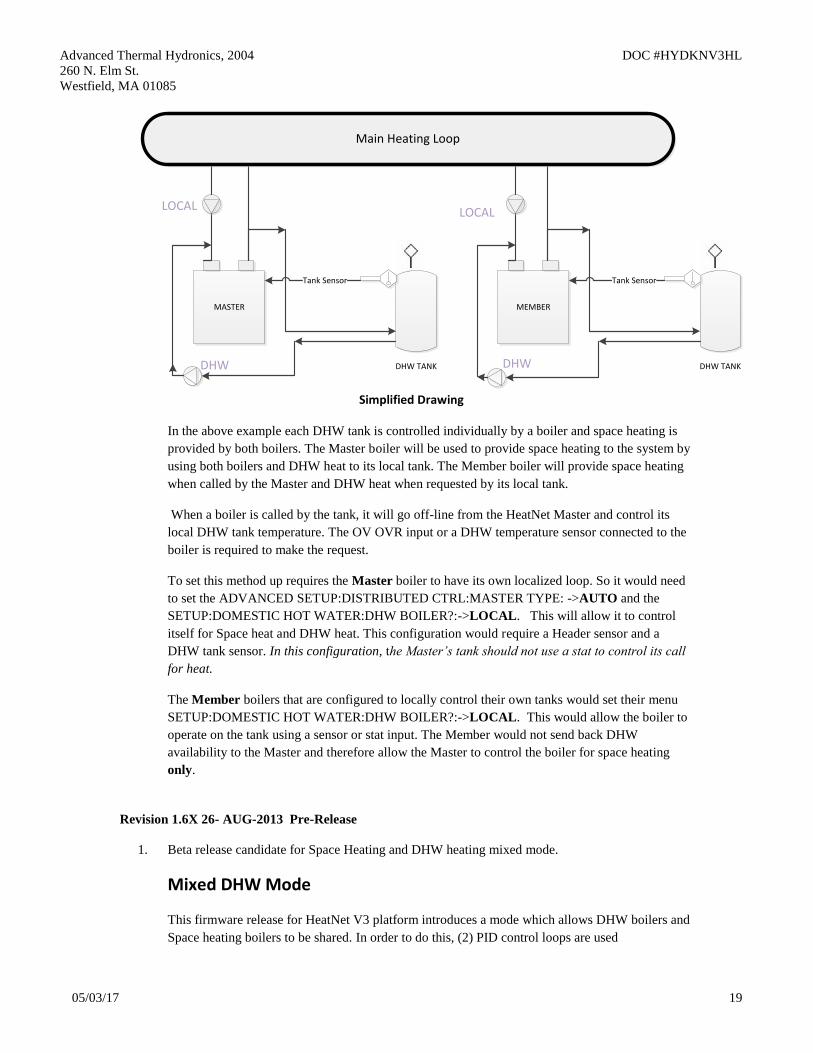
In the above example each DHW tank is controlled individually by a boiler and space heating is
provided by both boilers. The Master boiler will be used to provide space heating to the system by
using both boilers and DHW heat to its local tank. The Member boiler will provide space heating
when called by the Master and DHW heat when requested by its local tank.
When a boiler is called by the tank, it will go off-line from the HeatNet Master and control its
local DHW tank temperature. The OV OVR input or a DHW temperature sensor connected to the
boiler is required to make the request.
To set this method up requires the Master boiler to have its own localized loop. So it would need
to set the ADVANCED SETUP:DISTRIBUTED CTRL:MASTER TYPE: ->AUTO and the
SETUP:DOMESTIC HOT WATER:DHW BOILER?:->LOCAL. This will allow it to control
itself for Space heat and DHW heat. This configuration would require a Header sensor and a
DHW tank sensor. In this configuration, the Master’s tank should not use a stat to control its call
for heat.
The Member boilers that are configured to locally control their own tanks would set their menu
SETUP:DOMESTIC HOT WATER:DHW BOILER?:->LOCAL. This would allow the boiler to
operate on the tank using a sensor or stat input. The Member would not send back DHW
availability to the Master and therefore allow the Master to control the boiler for space heating
only.
Revision 1.6X 26- AUG-2013 Pre-Release
1. Beta release candidate for Space Heating and DHW heating mixed mode.
Mixed DHW Mode
This firmware release for HeatNet V3 platform introduces a mode which allows DHW boilers and
Space heating boilers to be shared. In order to do this, (2) PID control loops are used
Advanced Thermal Hydronics, 2004 DOC #HYDKNV3HL
260 N. Elm St.
Westfield, MA 01085
05/03/17 20
Prior releases of HeatNet allowed (3) DHW control methods: dedicating the system to DHW,
allowing DHW and Space heating where only one could be used at a time, or taking a boiler off-
line to perform DHW Heating while leaving the remaining boilers to heat the space.
One limitation of the prior releases was that the HeatNet Master could not perform concurrent
DHW and space heating and the Master could not be taken off-line to perform DHW heating. This
limitation in a (2) boiler system created a condition where the Member could be taken off-line to
heat a tank, but the Master could not. This resulted in the Master remaining in standby.
Another limitation was that the local pump would always remain running when in DHW heating.
This additional method allows simultaneous control of two heating loops and overcomes the
limitations. The intention is to provide for a Space heating system loop and a DHW heating loop.
The prior method of taking a boiler off-line for DHW can also be employed with this method. This
allows for more configurations and the ability to allow the Master boiler to heat a tank
independently from the Member (When the Member has been pulled off-line for DHW heating
using prior methods).
The second DHW heating loop can be as small as one boiler and one tank or many boilers with
many tanks.
If DHW and Space heating boilers are to be mixed and controlled by the Master boiler, the menus
need to be set up properly. Also, it is important to pipe the boilers appropriately. The pump/valve
and changeover settings that have been provided are very flexible for ease in setting up system
configurations.
Two new screens and several menu items have been added to allow flexibility of the system.
Many of the menus are not visible until ADVANCED SETUP:DISTRIBUTED CTRL:MASTER
TYPE->MIXED is set on the Master boiler.
The new menu items are:
ADVANCED SETUP:DISTRIBUTED CTRL:MASTER TYPE: -> AUTO, DHW, HEATING,
MIXED.
AUTO is the normal method of operation as in prior releases.
DHW is for DHW heating only. A DHW sensor is required with no Header sensor
HEATING is for Space heating only, the AUTO setting performs the same. Requires Header
sensor.
MIXED is for mixed DHW and Space heating where the Master controls both. Requires a
Header and DHW sensor.
ADVANCED SETUP: MODULAR BOILER SET: -> SPACE HEATING, DHW HEATING
SPACE HEATING is the ADD BOILER, SHED BOILER, MODULATE DELAY TIME,
MOD MAX menus
DHW HEATING is the same as SPACE HEATING, but specific when boilers are running as
DHW
SETUP:DOMESTIC HOT WATER: DHW BOILER? NO, LOCAL, MIXED
NO is the setting when the boiler is not configured to perform DHW heating.

Advanced Thermal Hydronics, 2004 DOC #HYDKNV3HL
260 N. Elm St.
Westfield, MA 01085
05/03/17 21
LOCAL is for local DHW heating without the Master being able to call it. It’s own DHW
sensor or OV OVR input can be used. Boiler will be taken off-line from HeatNet to
perform DHW heating.
MIXED is used by the boiler to let the Master know it can perform DHW heating under
control of the Master boiler. It may also be taken off-line to provide LOCAL heating.
SETUP:DOMESTIC HOT WATER:MIXED DHW-SPACE:DHW SHARING -> OFF, NO
CYCLE, CYCLE
NO CYCLE allows the boiler to perform as a space or DHW heating boiler. DHW always
has priority and will override (steal) a space heating boiler that is running when none are
available to perform DHW heating. When this happens, the boiler will not shut down, but
keep running during the change from space heating to DHW (Hot Swap). Once the DHW
cycle completes, the boiler will shut down and wait to be called for space heating again.
CAUTION: If used in a low temperature heat pump system a forced shutdown may need
to occur. TBD
Flow proving contacts and valve proving contacts need to be taken into account here. If
the LOCAL PUMP OFF setting is set to YES, ensure enough time is given in LOCAL
DELAY to re-establish flow in the path to the tank before shutting off the local
pump/valve.
CYCLE allows the boiler to perform as a space or DHW heating boiler. DHW always has
priority and will override (steal) a space heating boiler that is running when none are
available to perform DHW heating. When this happens, the boiler will shut down and exit
the space heating mode. The boiler will then re-start as a DHW heating boiler. Once the
DHW cycle completes, the boiler will shut down and wait to be called for space heating
again.
OFF allows the boiler to perform as a space or DHW heating boiler, but will not allow a
space heating boiler that is running to be overridden if none are available. The system
acts on a “First Come First Serve” basis. The heating system should be sized
appropriately to minimize the chances of not providing sufficient DHW heat during cold
weather.
SETUP:DOMESTIC HOT WATER:MIXED DHW-SPACE:LOCAL PUMP OFF -> YES,
NO
YES will shut off the local pump/valve when DHW heating is in effect. If the boiler is
running in space heating mode, the LOCAL DELAY will be in effect before the local
pump/valve shuts off.
NO both the local and the DHW pump/valve will be enabled during DHW heating.
SETUP:DOMESTIC HOT WATER:MIXED DHW-SPACE:LOCAL DELAY: x seconds
X seconds is the time in seconds that the local pump/valve will remain on after the DHW
pump/valve is enabled before shutting off. This is part of the changeover process when
the boiler was running in space heating mode and now needs to provide DHW heating.
SETUP:DOMESTIC HOT WATER:MIXED DHW-SPACE:PURGE TO THE: TANK,
SPACE
Advanced Thermal Hydronics, 2004 DOC #HYDKNV3HL
260 N. Elm St.
Westfield, MA 01085
05/03/17 22
TANK will keep the DHW pump/valve enabled for the DHW POST PURGE time thus
purging the boilers heat into the tank.
SPACE will turn off the DHW pump after 5 seconds and enable the local pump/valve when a
DHW heating cycle completes. This allows dumping the remaining heat from the boiler
into the heating space (dump zone).
Status Screen:
In order to show the two simultaneous PIDs (Space Heating and DHW) a split screen has
been added. It can be accessed from the main RUN screen by pressing the Down key. The
Left side of the band will display the Space heating band. The right side will display the
DHW heating band.
In the split screen with DHW and Space heating, the DHW: run% will display mDHW:
run% when the Master boiler is running in mixed mode as a DHW boiler.
A second screen has been added primarily to display the START and STOP timers when the
DHW heating has a call for heat. This screen can be accessed by pressing the Down key
another time while in the split screen. The START and STOP timers here work the same as
the heating START and STOP timers.
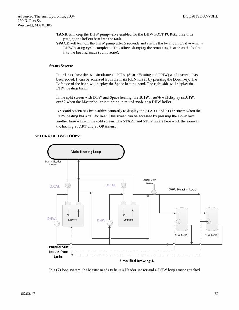
SETTING UP TWO LOOPS:
DHW TANK 2
MEMBER
Main Heating Loop
MASTER
DHW TANK 1
Master Header Sensor
Master DHW Sensor
DHW Heating Loop
Parallel Stat Inputs from
tanks.
DHW DHW
LOCALLOCAL
Simplified Drawing 1.
In a (2) loop system, the Master needs to have a Header sensor and a DHW loop sensor attached.
Advanced Thermal Hydronics, 2004 DOC #HYDKNV3HL
260 N. Elm St.
Westfield, MA 01085
05/03/17 23
First, on the Master boiler change the ADVANCED SETUP:DISTRIBUTED CTRL:MASTER
TYPE: ->MIXED. This will allow the modular boiler menu under ADVANCED
SETUP:MODULAR BOILER SET: -> DHW HEATING. Select DHW HEATING and change
the ADD BOILER DELAY, SHED BOILER DELAY, MODULATE DELAY TIME, and the
MOD MAX- LAST FIRE values to what works best for the DHW system loop for the system.
The next thing to setup is the SETUP:DOMESTIC HOT WATER: menu. For the Master to see
and control itself or Member Boiler(s) that are piped for DHW, the SETUP:DOMESTIC HOT
WATER:DHW BOILER?:-> must be set to MIXED on each Member ( This would include the
Master boiler if it is piped and a part of the DHW loop). When any boiler’s SETUP:DOMESTIC
HOT WATER:DHW BOILER?:-> is set to MIXED, HeatNet will see that the boiler is available
to be controlled by the Master, though the OR OVR input or the DHW temperature sensor
connected to the Member will still take the boiler off-line for local DHW heating ( an exception
would be Fail Safe mode).
The Menu items DHW SETPOINT, LOWER DHW DIFF, UPPER DHW DIFF, DHW
PRIORITY, POST PURGE, and USE SENSOR can be used as the Master’s control or on an
individual Member’s control. This is to allow mixing the prior DHW methods with the new mixed
DHW configurations. Backwards compatibility is also maintained.
The SETUP:DOMESTIC HOT WATER:MIXED DHW-SPACE: menu is used only when setting
up the second DHW heating loop. The first menu SETUP:DOMESTIC HOT WATER:MIXED
DHW-SPACE:DHW SHARING, when set to NO CYCLE creates a priority mode for firing DHW
boilers that are currently firing in a Space Heating mode. The Space heating boilers are overridden
with the DHW modulation value and fired as DHW boilers immediately with no shutdown cycle.
If a shutdown cycle is required set SHARING to CYCLE. You can also turn off the SHARING
(priority mode) and just use DHW boilers that are available (boiler is OFF).
The 2nd menu, SETUP:DOMESTIC HOT WATER:MIXED DHW-SPACE:LOCAL PUMP
OFF:NO allows the local pump to remain on at the same time as the DHW pump. If set to YES,
the local pump contact will open after the 3rd
menu item, LOCAL DELAY: time has expired. The
LOCAL PUMP OFF:YES sequence would be: Call for DHW heat -> if boiler is running, override
space heating -> close DHW relay contacts -> keep local pump relay contacts closed until the
LOCAL DELAY time has expired -> open local pump contacts.
The 4th
menu allows a dump zone to aid the purging of boiler’s heat energy into the Space or the
tank. Purging into the tank may overheat the tank, so the application should be considered. There
is a minimum DHW pump post purge of 5 seconds if the space heating dump zone is to be used or
if the DHW PUMP POST PURGE TIME is less than 5 seconds. If valves are used, the DHW
valve will begin closing after this time and the local valve will begin opening.
Since there are different delays when using local and DHW pumps versus local and DHW valves,
the timers have been included.
In the example (Simplified Drawing 1.): A system has (2) boilers and both of them are
configured as Space Heating and DHW Heating. Its cold out and all (2) boilers are providing
Space heating to a building. The DHW temperature in one tank drops below the stat setting and
needs to call a boiler to provide DHW heat. HeatNet evaluates the boilers that are running with the
least runtime and steals the boiler with the least runtime immediately, and begins monitoring the
Advanced Thermal Hydronics, 2004 DOC #HYDKNV3HL
260 N. Elm St.
Westfield, MA 01085
05/03/17 24
DHW temperature supplied to both tanks with the flow established by the DHW pumps in the
loop.
In this mode(SHARING=NO CYCLE), the boiler remains running, engages the DHW
pump/valve relay, stops or leaves open the local pump relay (next menu item), and changes to the
new DHW modulation rate. If the system had (1) boiler running in space heating out of the (2), it
would have fired the available boiler first, and then begun stealing running space heating boilers to
meet the DHW setpoint. Once the call-for-heat is satisfied, the stat on the tank opens and boilers
are returned to Space Heating.
In the example, the OV OVR input is used to enable DHW heating and then establish flow by
means of the boiler’s DHW pumps. Another example would be to use a pump to establish flow in
the DHW loop (example: secondary side of plate exchanger) and the OV OVR input can be used
to enable/disable DHW heating. In this way the Boilers will maintain temperature in the
secondary loop using the DHW sensor if there is enough thermal mass (such as in pool heating)
otherwise short cycling will occur.
SETTING UP INDIVIDUAL DHW CONTROL:
DHW TANK
MEMBER
Tank Sensor
DHW TANK
MASTER
Tank Sensor
Main Heating Loop
LOCAL LOCAL
DHW DHW
Simplified Drawing 2.
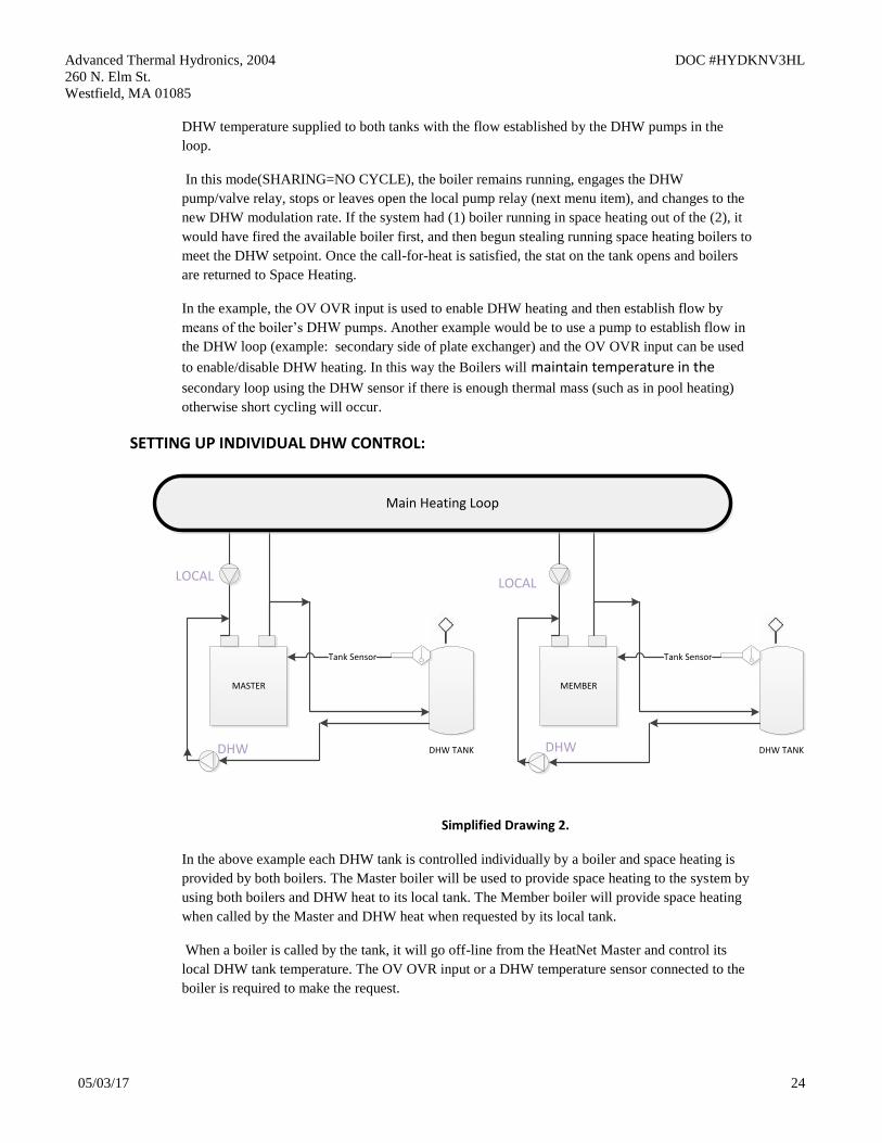
In the above example each DHW tank is controlled individually by a boiler and space heating is
provided by both boilers. The Master boiler will be used to provide space heating to the system by
using both boilers and DHW heat to its local tank. The Member boiler will provide space heating
when called by the Master and DHW heat when requested by its local tank.
When a boiler is called by the tank, it will go off-line from the HeatNet Master and control its
local DHW tank temperature. The OV OVR input or a DHW temperature sensor connected to the
boiler is required to make the request.
Advanced Thermal Hydronics, 2004 DOC #HYDKNV3HL
260 N. Elm St.
Westfield, MA 01085
05/03/17 25
To set this method up requires the Master boiler to have its own localized loop. So it would need
to set the ADVANCED SETUP:DISTRIBUTED CTRL:MASTER TYPE: ->MIXED and the
SETUP:DOMESTIC HOT WATER:DHW BOILER?:->MIXED. This will allow it to control
itself for Space heat and DHW heat. This configuration would require a Header sensor and a
DHW tank sensor. In this configuration, the Master’s tank should not use a stat to control its call
for heat.
The Member boilers that are configured to locally control their own tanks would set their menu
SETUP:DOMESTIC HOT WATER:DHW BOILER?:->LOCAL. This would allow the boiler to
operate on the tank using a sensor or stat input. The Member would not send back DHW
availability to the Master and therefore allow the Master to control the boiler for space heating
only.
DHW in FAILSAFE:
The DHW Failsafe mode is active when the SETUP:AUX FUNTIONS:FAILSAFE MODES:H-
NET COMM LOST:-> ON. If the Master Boiler’s communication is lost, and after 10 minutes of
not being restored, the boiler enters a stand-alone mode. The Heat Demand on that boiler becomes
active and not only runs to provide failsafe space heating, but DHW heat as well. The STATUS
screen will display an ‘*’ and H-NET LOST. If a stat is used, the boiler will run to 100% until the
stat removes the DHW call. If a temperature sensor is used, the boiler will modulate to maintain
tank temperature. The DHW Call always has priority over space heating.
The Failsafe boiler needs to either have a stat input from a DHW tank or a temperature sensor
connected to a tank. When these sensors are connected normally, they would override any call to
the boiler by the Master (when in SETUP:DOMESTIC HOT WATER:DHW BOILER?:->
MIXED mode) and enter DHW heating mode. With the Failsafe active, this function is inhibited
and the Failsafe boiler only responds to these inputs with the loss of the Master’s communication.
Revision 1.52 17- July-2013 Pre-Release
1. Fixed an issue where the IGN value used during calibration would not save (occurred during
development of V1.51). The restoration of the saved value using the BACK key was not being
done properly.
2. Increased the accuracy of the Calibration values when saving. These include the MIN VFD,
MAX VFD, and IGN settings.
3. Improved the way the High Delta T, and Low Delta T protection functions. Instead of dropping
to half rate, a linear de-limiting method is used. This method limits the input of the boiler
slowly, and allows the boiler to operate at High Delta T and Low Delta T conditions longer at
the maximum limited input, while still protecting the boiler.
Revision 1.40-1.50 28-Feb-2013 Pre-Release
Advanced Thermal Hydronics, 2004 DOC #HYDKNV3HL
260 N. Elm St.
Westfield, MA 01085
05/03/17 26
1. Fixed a bug that was introduced in the V1.3Z pre-release code that wouldn’t accept the 4-20mA
setpoint values until the boiler was power-cycled. These values were corrupt.
2. Added a BTU load measurement when using a flow meter with a System Return sensor. This
value can be viewed under the FLOW window. The BTU value is relative to the accuracy of
the sensors and is only available as an estimate of the BTU load.
The BTU load value may also be accessed through Modbus read registers 30242 (upper 16 bit
word) & 30243 (lower 16 bit word). These two words will need to be combined in order to get
the BTU load value.
When using the BMS GPM register the BTU values are only calculated to a whole GPM since
the BMS GPM register currently does not support floating point numbers.
3. Replaced the 4-20 mA setpoint settings when using 0-10V input. The 0-10 V input may now be
set using voltage settings rather than current.
4. Added (2) log entry types for debugging faults.
A. If the Main Valve signal is lost from the Ignition Control while the boiler is running a log
entry, LOST MAIN VALVE with the modulation value being sent to the blower at the
time of loss. Example: LOST MAIN VALVE 40
B. If the Blower signal is lost from the Ignition Control while the boiler is running a log
entry, LOST BLOWER with the modulation value being sent to the blower at the time of
loss. Example: LOST BLOWER 27
5. Normalized the 0-10 volt control signal for direct fire applications. Such that: 1 volt will track
linearly by 10%. So, 1v=10%, 2v=20%, 3v=30%, 4v=40%... The control signal will still be
limited by the turndown and the 4-20mA INPUT menu.
6. Removed the ability to silence the alarm with the push button. Alarm silencing is now done by
pressing the BACK and ENTER keys at the same time. The input that was used for the
ALARM SILENCE will now be dedicated to a stack sensor.
7. Added the auto detection of a Stack Sensor. If the Stack Sensor is present, a warning will occur
at 325F and greater, and an Alarm will occur at 350F and greater. During the Warning and
Alarm conditions the boiler will be limited to half the rate of fire requested. The only
difference between the two is that the Alarm will close the Alarm relay.
The Stack sensor should be a 1k ohm platinum type sensor. Part # 0040-1300. Currently, a 10k
version is not supported due to the maximum temperature of the flue.
8. Fixed an issue with HeatNet Pro not being able to resolve the HeatNet 3 board.
Revision 1.30 20-Feb-2013 Pre-Release
This revision addresses some bug fixes from the prior pre-release firmware and gives more control in
overcoming issues with variable flow systems.
1. Fixed a bug that was introduced in the V1.20 where the boiler would not load the HEAT
BAND when it was changed, but would load the changed value when power cycled.
2. Fixed a bug that was introduced in the V1.20 pre-release code that disabled the 4-20mA/0-10V
setpoint when the boiler was operating as a Master boiler.
Advanced Thermal Hydronics, 2004 DOC #HYDKNV3HL
260 N. Elm St.
Westfield, MA 01085
05/03/17 27
3. Fixed an issue that happens when a Modbus Setpoint is written and the outdoor reset is active.
The (2) setpoints would override each other randomly.
With this release, if a higher level setpoint control is lost, the next level setpoint control is used
until the System Setpoint is loaded. The setpoints are prioritized in the following order:
1. 0-10V, 4-20Ma setpoint Control
2. BMS, Modbus Setpoint
3. Outdoor Reset Setpoint
4. System Setpoint
Any Setbacks that are active are then applied.
4. Added the ability of a Building Management System (BMS) to limit the # of HeatNet boilers
allowed to fire. With this addition; when a system has a fixed amount of boilers that HeatNet
reports are available, the BMS can now limit the # of boilers that can fire. The BMS can write
the GPM value it has for flow, or directly write a register with how many boilers HeatNet can
control. If the BMS GPM flow feature is active, the direct control becomes inactive.
This change is in response to requests to limit HeatNet’s control of adding boilers when the
system flow changes. In variable flow systems, when the system flow is reduced, any boiler(s)
that is/are running may go into a high delta temperature across the boiler. When this occurs, the
boiler(s) will enter a high delta T protection mode and drop to half of the rate called for. At this
time, the Master may not be able to achieve setpoint due to the reduced output with the running
boiler(s). The Master will then call on more boilers to achieve setpoint, but at the same time
splitting the already reduced flow through the boiler(s) it has running. The flow can now be so
reduced that the boiler(s) trip their operating limits or even their high limits.
Note: using these features can limit HeatNet’s ability to maintain setpoint.
1.) Flow Limited Control: This method helps HeatNet to limit the # of boilers firing
based on the System Flow in GPM. In variable flow systems, this will limit HeatNet’s
ability to add new boilers when insufficient flow is available. The # of boilers
allowed to fire is determined by:
# of HeatNet boilers that can fire = BMS GPM Set Rate/ LOWEST FLOW
To activate this flow limited feature for use with a BMS:
a. Set ADVANCED SETUP: FLOWMETER: FLOWMETER? YES
b. Set ADVANCED SETUP: FLOWMETER: GLYCOL MIX ? % , Currently,
any mix over 10% de-rates the flow by 30% (rule of thumb method).
Example: if the LOWEST FLOW = 50 GPM, HeatNet will calculate a New
Lowest Flow required to be 65 GPM. The LOWEST FLOW does not need to
be changed, but is calculated to 65 GPM and that value is used by HeatNet.
c. Set ADVANCED SETUP: FLOWMETER: INPUT TYPE to BMS.
d. Set ADVANCED SETUP: FLOWMETER: SET PARAMETERS?
Enter LOWEST FLOW: (The automatic value loaded will equal the lowest
flow required for this boiler (it is adjustable). It should be = to the lowest flow
of the largest boiler in the system).
e. The HIGHEST FLOW & FLOW FACTOR are currently not used with this
release. Once flow meter manufacturers have been determined, new firmware
will become available.
f. Write to address BMS GPM register 40019 with a valid flow (0 -1500 GPM).
Advanced Thermal Hydronics, 2004 DOC #HYDKNV3HL
260 N. Elm St.
Westfield, MA 01085
05/03/17 28
g. If a new GPM value is not written within 10 minutes, this feature will be
deactivated until a new flow value is written. Ensure periodic updates of
the flow register are done within 10 minute intervals.
h. To check if HeatNet is in a flow limited state, read the boiler status 4 register
starting at address 30160 for the Master Boiler; if Status 4 bit (12) is set, it
indicates that the HeatNet control is running with limited boilers due to
insufficient flow derived from the GPM value.
2.) Boilers Limited Control: This feature allows the BMS to directly change the amount
of boilers that HeatNet can control.
To Activate the Boiler limited feature:
a. Read Modbus address 30241 to see how many boilers HeatNet has available
to fire. MODBUS AVAILABLE BOILERS register.
b. Determine how many boilers the BMS system will require.
c. Write to address BMS LIMIT BOILERS register 40020 with the # of boilers
HeatNet is allowed to control (0 - 16).
d. If a new boiler # value is not written within 10 minutes, this feature will
be deactivated until a new boiler # is written. Ensure periodic updates of
the flow register are done within 10 minute intervals.
e. To check if HeatNet is in a BMS limited state, read the boiler status 4 register
starting at address 30160 for the Master Boiler; if Status 4 bit (13) is set, it
indicates that the HeatNet control is running with limited boilers due to the
BMS system specifying BMS LIMIT BOILERS being less than the available
boilers.
4. Added the ability of a Flow Meter to control the # of HeatNet boilers allowed to fire. With this
addition; HeatNet will look at the # of boilers it has available, and the amount of system flow
to determine how many of boilers it can fire. As an Example: An Onicon F-1210 Flow Meter
provides simultaneous 0-10V and 4-20mA outputs, so if the BMS system is using (1) output,
the other may be used by HeatNet.
To activate this flow limited feature for use with an Onicon Flow Meter F-1210:
a. Set ADVANCED SETUP: FLOWMETER: FLOWMETER? YES
f. Set ADVANCED SETUP: FLOWMETER: GLYCOL MIX ? % , Currently,
any mix over 10% de-rates the flow by 30% (rule of thumb method).
Example: if the LOWEST FLOW = 50 GPM, HeatNet will calculate a New
Lowest Flow required to be 65 GPM. The LOWEST FLOW does not need to
be changed, but is calculated to 65 GPM and that value is used by HeatNet.
b. Set ADVANCED SETUP: FLOWMETER: INPUT TYPE to mA 2 or VOLTS
2 depending on whether a 4-20 milliamp or 0-10 volt signal is used. The
connection should be made from the Flow Meter to analog input 4-20 mA (2).
c. Select ADVANCED SETUP: FLOWMETER: SET PARAMETERS?
Enter LOWEST FLOW: (The automatic value loaded will equal the lowest
flow required for this boiler (it is adjustable). It should be equal to the lowest
flow of the largest boiler in the system).
d. Set the ADVANCED SETUP: FLOWMETER: FULL SCALE value to the
full scale reading on the calibration card that came with the flow meter.
e. The HIGHEST FLOW & FLOW FACTOR currently are not used with this
release.
f. These settings will use the equations:
Advanced Thermal Hydronics, 2004 DOC #HYDKNV3HL
260 N. Elm St.
Westfield, MA 01085
05/03/17 29
4-20 mA: Measured GPM = (signal/16) * FULL SCALE flow
0-10 Volt: Measured GPM = (signal/10) * FULL SCALE flow
These settings may work with other flow meters (consult their respective
manuals).
Revision 1.20 18-Jan-2013 Pre-Release
1. Replaced the DHW differential temperature setting with an upper and lower control band limit
(UPPER DHW DIFF & LOWER DHW DIFF). Instead of using just a differential temperature
below the setpoint, the differential temperature now consists of a lower band limit and an upper
band limit which can be set independently. This allows a DHW tank temperature to be
maintained using a PID rather than the boiler shutting off at setpoint.
The LOWER DHW DIFF brings on DHW heating when the DHW tank temperature falls
below the (DHW SETPOINT - LOWER DHW DIFF). The boiler then maintains temperature
until the (DHW SETPOINT + UPPER DHW DIFF) is exceeded. The UPPER DHW DIFF
must be set properly to prevent overheating of the tank. The UPPER DHW DIFF + DHW
SETPOINT should be set to the tank temperature required. In this way the tank temperature -
UPPER DHW DIFF will be maintained while a continuous demand is present. When the
continuous demand ends, the tank will be left at the (DHW SETPOINT + UPPER DHW DIFF)
temperature.
2. Issue with variations in the blowers caused some blowers to lockout on current limit when
starting. Lowered the starting % for a slow start of the blower to 10% from 14%. Also added a
slow step rate to get to pre-purge.
3. When using the Delta T function and clamping the fire rate to half input, the input could fall
lower than the MIN VFD setting. This condition occurs when the firing rate is less than ½ of
the MAX VFD setting. The problem was that the clamp value was set to the minimum firing
range setting rather than the MIN VFD setting. This has been corrected to clamp the ½ input
rate to the MIN VFD setting.
Revision 1.11 22 – July – 2012
1. Minor change to allow the Blower menu items to be initialized even when an Ametek Blower
is not present after a product change. These include ACCELERATE, DECELLERATE and
SOFT START. Changing the menu BOILET TYPE: PRODUCT from a boiler which had a
VFD, to an Ametek Blower would require a power cycle to set these BLOWER menu item
values. This was sometimes not done and resulted in a service call. It is still required to power
cycle the boiler after making a product change to initialize all settings.
Revision 1.10 22 – June – 2012
1. Added support for setting up the Minimum Input on the KN16.
Revision 1.09 1 – June – 2012
1. The Alarm Silence under Aux Functions did not save the “IN USE” value. The Alarm Silence,
“IN USE” selection is now saved.
Advanced Thermal Hydronics, 2004 DOC #HYDKNV3HL
260 N. Elm St.
Westfield, MA 01085
05/03/17 30
2. If the Alarm Silence switch is used with the Stack sensor input the DIP switch S5 position 3,
must be set to the 10K STACK position. The message “DIP S5.3 = 10K Stack was added in the
Alarm Silence menu as a notice. If no sensor is selected for the stack using S5, and the stack
sensor input is used for alarm silence, the input will be detected as a silence alarm condition.
This was due to a lack of bias on the stack sensor input. Setting the S5 switch to 10k STACK
provides this bias.
3. When the Factory Reset is used, the Turndown Ratio and Blower type are reset to factory
defaults of 4:1 and VFD blower type. The Boiler Type is left at the current setting. With this
release, a Factory Reset leaves the Boiler Type, Turndown Ratio, and Blower type at the
current settings.
Revision 1.08 24 – May – 2012 Initial Release
1. Initial release to manufacturing.