Embed Size (px)
Citation preview
Th is manual is intended only for use by a qualifi ed heating installer/technician. Read and follow this manual, all supplements and related instructional information provided with the boiler. Install, start and service the boiler only in the sequence and methods given in these instructions. Failure to do so can result in severe personal injury, death or substantial property damage.
Do not use the boiler during construction. Construction dust and particulate, particularly drywall dust, will cause contamination of the burner, resulting in possible severe personal injury, death or substantial property damage. Th e boiler can only be operated with a dust-free air supply. Follow the instruction manual procedures to duct air to the boiler air intake. If the boiler has been contaminated by operation with contaminated air, follow the instruction manual guidelines to clean, repair or replace the boiler if necessary.
Affi x these instructions near to the boiler/water heater. Instruct the building owner to retain the instructions for future use by a qualifi ed service technician, and to follow all guidelines in the User’s Information Manual.
P/N 42-9540 11/12 Copyright 2012 Advanced Thermal Hydronics
Cast Iron Condensing Boilers
Models KN-2 and KN-4
Vent/Air ManualInstallation Instructions
for Vent and Air Piping
Also read and follow:
KN Boiler ManualKN Control Manual
KN-2/4 VAM2-0714
KN-2 only
P/N 42-9540 11/12 Copyright 2012
Page 2 KN INSTALLATION INSTRUCTIONS FOR VENT AND AIR PIPING
The KN boiler — Vent and air piping options
Vent and air piping, general
Pages 2, 3 and 4 are a brief overview of the options for vent and air piping confi gurations. Page 3 and 4 gives a summary and brief list of requirements for each of the vent/air confi guration options.
When air is taken from the boiler room (no air pipe connected to the boiler air inlet fi tt ing), follow the instructions in the KN Boiler manual to ensure the boiler room has proper openings for combustion air and ventilation.
Vent piping
Category II & IV venting only
Category IV Individual Vent: All KN boilers require vent piping listed for use in pressurized, condensing operation. Use only the materials specifi ed in this manual. Category II Common Vent: Cosult factory when common venting multiple boilers and/or use an engineered venting system solution.
Vent pipe options
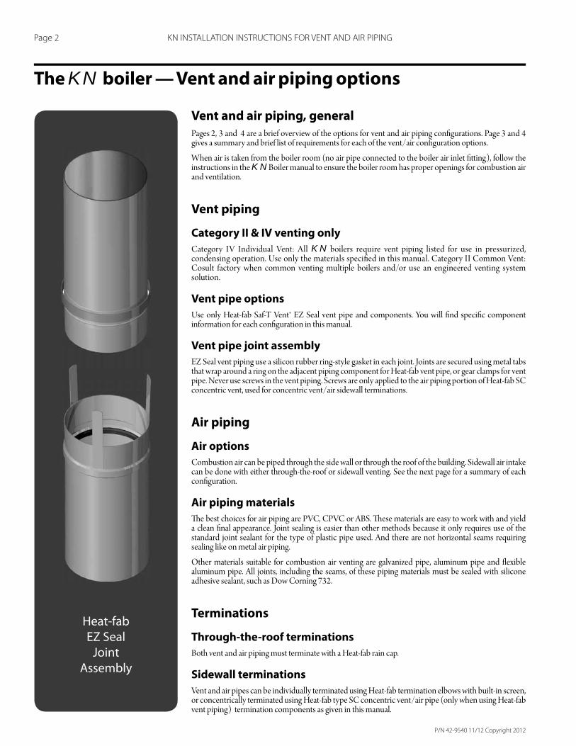
Use only Heat-fab Saf-T Vent® EZ Seal vent pipe and components. You will fi nd specifi c component information for each confi guration in this manual.
Vent pipe joint assembly
EZ Seal vent piping use a silicon rubber ring-style gasket in each joint. Joints are secured using metal tabs that wrap around a ring on the adjacent piping component for Heat-fab vent pipe, or gear clamps for vent pipe. Never use screws in the vent piping. Screws are only applied to the air piping portion of Heat-fab SC concentric vent, used for concentric vent/air sidewall terminations.
Air piping
Air options
Combustion air can be piped through the side wall or through the roof of the building. Sidewall air intake can be done with either through-the-roof or sidewall venting. See the next page for a summary of each confi guration.
Air piping materials
Th e best choices for air piping are PVC, CPVC or ABS. Th ese materials are easy to work with and yield a clean fi nal appearance. Joint sealing is easier than other methods because it only requires use of the standard joint sealant for the type of plastic pipe used. And there are not horizontal seams requiring sealing like on metal air piping.
Other materials suitable for combustion air venting are galvanized pipe, aluminum pipe and fl exible aluminum pipe. All joints, including the seams, of these piping materials must be sealed with silicone adhesive sealant, such as Dow Corning 732.
Terminations
Through-the-roof terminations
Both vent and air piping must terminate with a Heat-fab rain cap.
Sidewall terminations
Vent and air pipes can be individually terminated using Heat-fab termination elbows with built-in screen, or concentrically terminated using Heat-fab type SC concentric vent/air pipe (only when using Heat-fab vent piping) termination components as given in this manual.
Heat-fab
EZ Seal
Joint
Assembly
P/N 42-9540 11/12 Copyright 2012
Page 3 KN INSTALLATION INSTRUCTIONS FOR VENT AND AIR PIPING
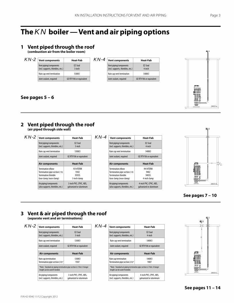
3 Vent & air piped through the roof(separate vent and air terminations)
KN-2 Vent components Heat-Fab KN-4 Vent components Heat-Fab
Vent piping/components
(incl. supports, thimbles, etc.)
EZ-Seal
3-inch
Vent piping/components
(incl. supports, thimbles, etc.)
EZ-Seal
4-inch
Rain cap vent termination 5300CI Rain cap vent termination 5400CI
Joint sealant, required GE RTV106 or equivalent Joint sealant, required GE RTV106 or equivalent
Air components Heat-Fab Air components Heat-Fab
Rain cap termination
Termination pipe section (3 ft)*
5300CI
9307
Rain cap termination
Termination pipe section (3 ft)*
5400CI
9407
*Note: Standard air piping termination pipe section is 3 feet. A longer
length can be used if needed.
*Note: Standard air piping termination pipe section is 3 feet. A longer
length can be used if needed.
Air piping/components
(incl. supports, thimbles, etc.)
3-inch PVC, CPVC, ABS,
galvanized or aluminum
Air piping/components
(incl. supports, thimbles, etc.)
4-inch PVC, CPVC, ABS,
galvanized or aluminum
1 Vent piped through the roof(combustion air from the boiler room)
KN-2 Vent components Heat-Fab KN-4 Vent components Heat-Fab
Vent piping/components
(incl. supports, thimbles, etc.)
EZ-Seal
3-inch
Vent piping/components
(incl. supports, thimbles, etc.)
EZ-Seal
4-inch
Rain cap vent termination 5300CI Rain cap vent termination 5400CI
Joint sealant, required GE RTV106 or equivalent Joint sealant, required GE RTV106 or equivalent
See pages 5 – 6
2 Vent piped through the roof(air piped through side wall)
KN-2 Vent components Heat-Fab KN-4 Vent components Heat-Fab
Vent piping/components
(incl. supports, thimbles, etc.)
EZ-Seal
3-inch
Vent piping/components
(incl. supports, thimbles, etc.)
EZ-Seal
4-inch
Rain cap vent termination 5300CI Rain cap vent termination 5400CI
Joint sealant, required GE RTV106 or equivalent Joint sealant, required GE RTV106 or equivalent
Air components Heat-Fab Air components Heat-Fab
Termination elbow
Termination pipe section (1 ft)
Termination thimble
Gear clamp (nose clamp)
9314TERM
9302
9393S
3-inch clamp
Termination elbow
Termination pipe section (1 ft)
Termination thimble
Gear clamp (nose clamp)
9414TERM
9402
9493S
4-inch clamp
Air piping/components
(also supports, thimbles, etc.)
3-inch PVC, CPVC, ABS,
galvanized or aluminum
Air piping/components
(also supports, thimbles, etc.)
4-inch PVC, CPVC, ABS,
galvanized or aluminum
See pages 7 – 10
See pages 11 – 14
The KN boiler — Vent and air piping options
P/N 42-9540 11/12 Copyright 2012
Page 4 KN INSTALLATION INSTRUCTIONS FOR VENT AND AIR PIPING
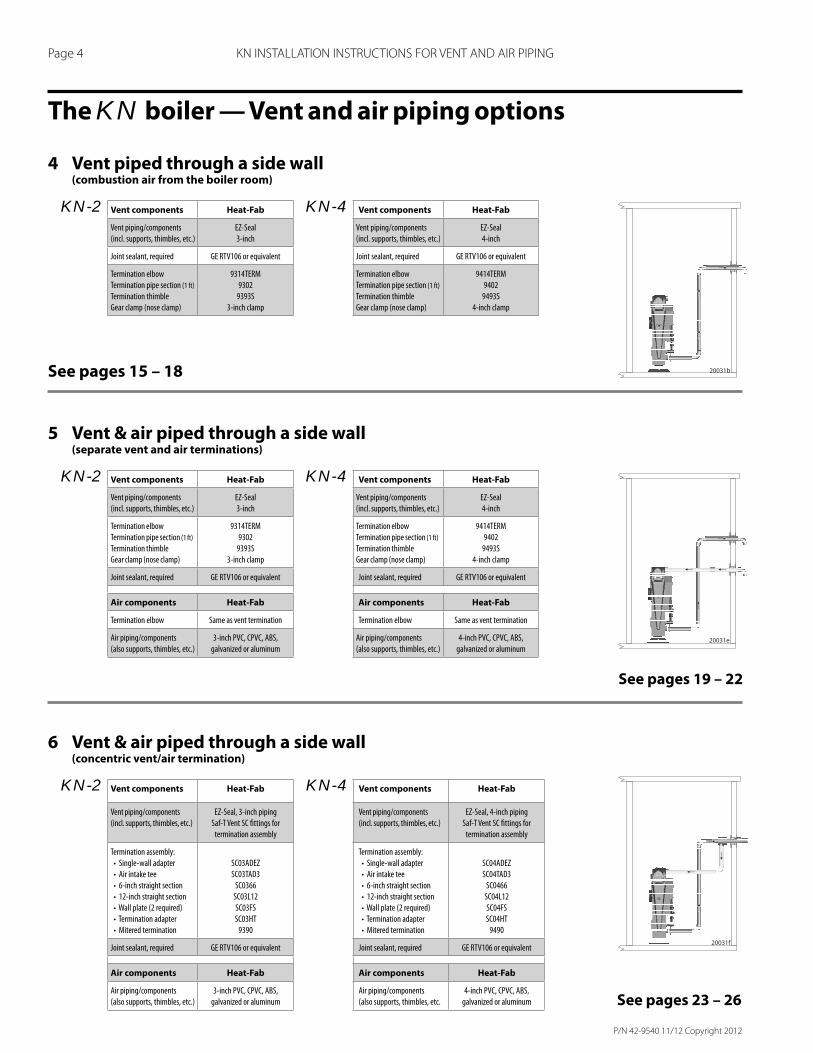
4 Vent piped through a side wall(combustion air from the boiler room)
KN-2 Vent components Heat-Fab KN-4 Vent components Heat-Fab
Vent piping/components
(incl. supports, thimbles, etc.)
EZ-Seal
3-inch
Vent piping/components
(incl. supports, thimbles, etc.)
EZ-Seal
4-inch
Joint sealant, required GE RTV106 or equivalent Joint sealant, required GE RTV106 or equivalent
Termination elbow
Termination pipe section (1 ft)
Termination thimble
Gear clamp (nose clamp)
9314TERM
9302
9393S
3-inch clamp
Termination elbow
Termination pipe section (1 ft)
Termination thimble
Gear clamp (nose clamp)
9414TERM
9402
9493S
4-inch clamp
See pages 15 – 18
5 Vent & air piped through a side wall(separate vent and air terminations)
KN-2 Vent components Heat-Fab KN-4 Vent components Heat-Fab
Vent piping/components
(incl. supports, thimbles, etc.)
EZ-Seal
3-inch
Vent piping/components
(incl. supports, thimbles, etc.)
EZ-Seal
4-inch
Termination elbow
Termination pipe section (1 ft)
Termination thimble
Gear clamp (nose clamp)
9314TERM
9302
9393S
3-inch clamp
Termination elbow
Termination pipe section (1 ft)
Termination thimble
Gear clamp (nose clamp)
9414TERM
9402
9493S
4-inch clamp
Joint sealant, required GE RTV106 or equivalent Joint sealant, required GE RTV106 or equivalent
Air components Heat-Fab Air components Heat-Fab
Termination elbow Same as vent termination Termination elbow Same as vent termination
Air piping/components
(also supports, thimbles, etc.)
3-inch PVC, CPVC, ABS,
galvanized or aluminum
Air piping/components
(also supports, thimbles, etc.)
4-inch PVC, CPVC, ABS,
galvanized or aluminum
6 Vent & air piped through a side wall(concentric vent/air termination)
KN-2 Vent components Heat-Fab KN-4 Vent components Heat-Fab
Vent piping/components
(incl. supports, thimbles, etc.)
EZ-Seal, 3-inch piping
Saf-T Vent SC fi ttings for
termination assembly
Vent piping/components
(incl. supports, thimbles, etc.)
EZ-Seal, 4-inch piping
Saf-T Vent SC fi ttings for
termination assembly
Termination assembly:
• Single-wall adapter
• Air intake tee
• 6-inch straight section
• 12-inch straight section
• Wall plate (2 required)
• Termination adapter
• Mitered termination
SC03ADEZ
SC03TAD3
SC0366
SC03L12
SC03FS
SC03HT
9390
Termination assembly:
• Single-wall adapter
• Air intake tee
• 6-inch straight section
• 12-inch straight section
• Wall plate (2 required)
• Termination adapter
• Mitered termination
SC04ADEZ
SC04TAD3
SC0466
SC04L12
SC04FS
SC04HT
9490
Joint sealant, required GE RTV106 or equivalent Joint sealant, required GE RTV106 or equivalent
Air components Heat-Fab Air components Heat-Fab
Air piping/components
(also supports, thimbles, etc.)
3-inch PVC, CPVC, ABS,
galvanized or aluminum
Air piping/components
(also supports, thimbles, etc.
4-inch PVC, CPVC, ABS,
galvanized or aluminum
See pages 19 – 22
See pages 23 – 26
The KN boiler — Vent and air piping options
P/N 42-9540 11/12 Copyright 2012
Page 5 KN INSTALLATION INSTRUCTIONS FOR VENT AND AIR PIPING
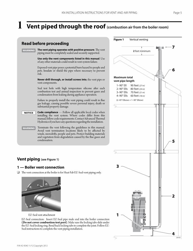
Vent piped through the roof (combustion air from the boiler room)1Figure 1 Vertical venting
Vent piping (see Figure 1)
1 — Boiler vent connection
❑ Th e vent connection at the boiler is for Heat-Fab EZ-Seal vent piping only.
EZ-Seal vent att achment
EZ-Seal connection: Insert EZ-Seal pipe male end into the boiler connection (Do not cover combustion test port). Make sure the locking tabs slide under the EZ-Seal locking ring. Bend back locking tabs to complete the joint. Follow EZ-Seal instructions to complete the vent piping installation.
Read before proceeding
The vent piping operates with positive pressure. Th e vent piping must be completely sealed and securely supported.
Use only the vent components listed in this manual. Use of any other materials could result in vent system failure.
Exposed vent pipe poses a potential burn hazard to people and pets. Insulate or shield the pipe where necessary to prevent risk.
Never drill through, or install screws into, the vent pipe or vent components.
Seal test hole with high temperature silicone aft er each combustion test and annual inspection to prevent gases and condensation from leaking during appliance operation.
Failure to properly install the vent piping could result in fl ue gas leakage, causing possible severe personal injury, death or substantial property damage.
Code compliance — Follow all applicable local codes when installing the vent system. Where codes diff er from this manual, follow code requirements. Contact Advanced Th ermal Hydronics if you have any questions regarding the installation.
Terminate the vent following the guidelines in this manual. Avoid vent termination locations likely to be aff ected by winds, snowdrift s, people and pets. Protect building materials and vegetation from degradation caused by the fl ue gases and condensation.
P/N 42-9540 11/12 Copyright 2012
Page 6 KN INSTALLATION INSTRUCTIONS FOR VENT AND AIR PIPING
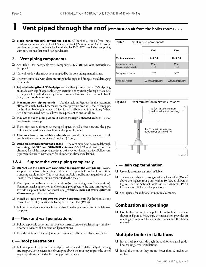
Vent piped through the roof (combustion air from the boiler room) (cont.)1Table 1 Vent system components
Figure 2 Vent termination minimum clearances
❑ Slope horizontal runs toward the boiler. All horizontal runs of vent pipe must slope continuously at least 1/4 inch per foot (21 mm per meter) to ensure condensate drains completely back to the boiler. DO NOT install the vent piping with any sections that could trap condensate.
2 — Vent piping components
❑ See Table 1 for acceptable vent components. NO OTHER vent materials are acceptable.
❑ Carefully follow the instructions supplied by the vent piping manufacturer.
❑ Th e vent joints seal with elastomer rings in the pipe and fi tt ings. Avoid damaging these seals.
❑ Adjustable lengths of EZ-Seal pipe — Length adjustments with EZ-Seal piping are made with slip-fi t adjustable length sections, not by cutt ing the pipe. Make sure the adjustable length does not jut into elbows or terminations. Th is could block fl ue gas and condensate fl ow.
❑ Maximum vent piping length — See the table in Figure 3 for the maximum allowable length. Each elbow causes the same pressure drop as 10 feet of vent pipe, so the allowable length reduces 10 feet for each elbow used in the piping. When 45° elbows are used, two 45° elbows are equivalent to one 90° elbow.
❑ Insulate the vent piping where it passes through unheated areas to prevent condensate freeze-up.
❑ If the pipe passes through an occupied space, install a chase around the pipe, following the vent pipe instructions and applicable codes.
❑ Clearance from combustible materials — Provide minimum clearance to all combustible materials of at least 2 inches (51 mm).
❑ Using an existing chimney as a chase — Th e vent piping can be routed through an existing UNUSED and STRAIGHT chimney. DO NOT vent directly into the chimney. Install the vent piping so it can be inspected aft er installation. Follow vent pipe manufacturer’s instructions for chimney-as-chase installations.
3 & 4 — Support the vent piping completely
❑ DO NOT use the boiler vent connection to support the vent piping. Provide support straps from the ceiling and pedestal supports from the fl oor; utilize noncombustible saddle. Th is is required on ALL installations, regardless of the length of the horizontal piping connected to the boiler.
❑ Vent piping cannot be supported from above (such as relying on roof jack sections). You must install supports on the horizontal piping before the vent turns upward. Provide a support on the horizontal piping within 6 inches of every upturned elbow to support the vertical run.
❑ Install at least one support on every horizontal run. For horizontal runs longer than 5 feet (1.5 m), install a support every 3 feet (0.9 m).
❑ Follow the vent pipe manufacturer’s instructions for placement and installation of supports.
5 — Floor and wall penetrations
❑ Follow applicable codes and the vent pipe instructions to install fi re stops, thimbles or other devices at all fl oor and wall penetrations.
❑ Provide minimum 2 inches (51 mm) clearance to all combustible construction.
6 — Roof penetrations
❑ Follow applicable codes and the vent pipe instructions to install a roof jack, fl ashing and support. Long extensions of vent pipe above the roof may require the use of guy supports as specifi ed in the vent pipe instructions.
7 — Rain cap termination
❑ Use only the rain caps listed in Table 1.
❑ Th e rain cap exhaust opening must be at least 2 feet (0.6 m) above the highest roof point within 10 feet, as shown in Figure 1. See the National Fuel Gas Code, ANSI/NFPA 54 for details on pitched roof applications.
❑ See Figure 2 for additional minimum clearances.
Combustion air openings
❑ Combustion air must be supplied from the boiler room as shown in Figure 1. Make sure the installation provides air openings as required by applicable codes and the Boiler manual.
Multiple boiler installations
❑ Install multiple vents through the roof following all guide-lines for single-vent installations.
❑ Install the vents so they are no closer than 12 inches on centers.
KN-2 KN-4
Vent components Heat-Fab Heat-Fab
Vent piping/components
(incl. supports, thimbles, etc.)
EZ-Seal
3-inch
EZ-Seal
4-inch
Rain cap vent termination 5300CI 5400CI
Joint sealant, required GE RTV106 or equivalent GE RTV106 or equivalent
P/N 42-9540 11/12 Copyright 2012
Page 7 KN INSTALLATION INSTRUCTIONS FOR VENT AND AIR PIPING
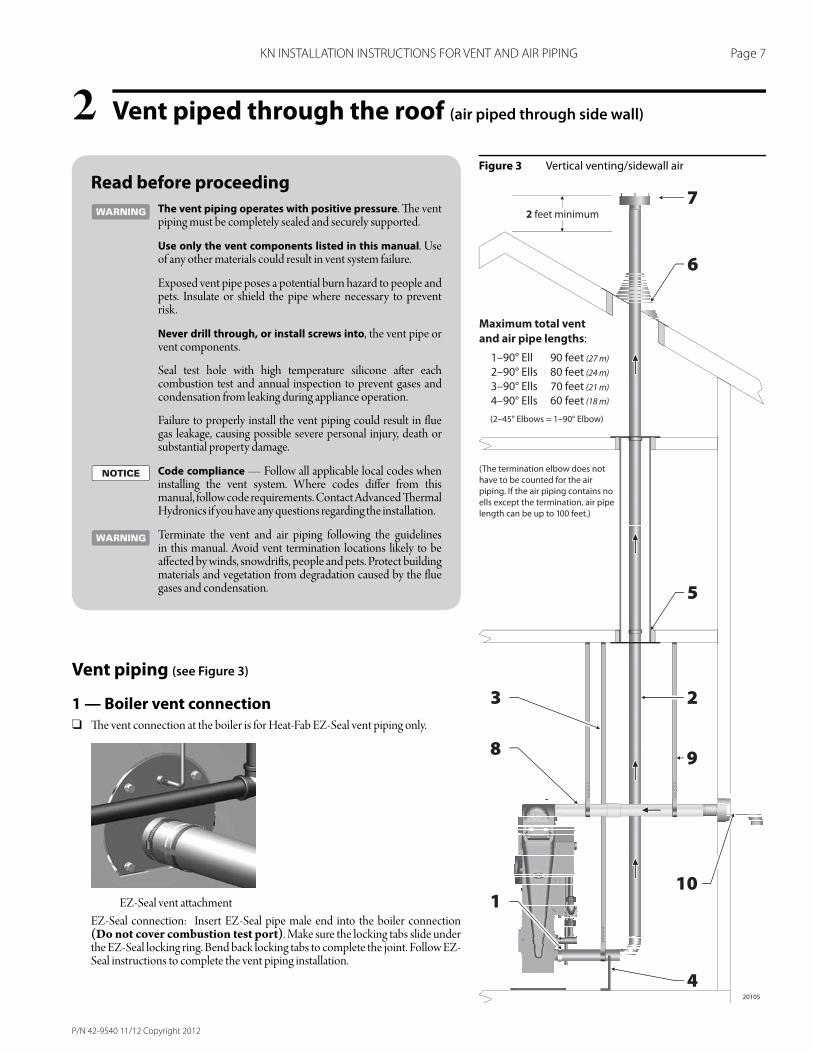
Vent piped through the roof (air piped through side wall)2Figure 3 Vertical venting/sidewall air
Read before proceeding
The vent piping operates with positive pressure. Th e vent piping must be completely sealed and securely supported.
Use only the vent components listed in this manual. Use of any other materials could result in vent system failure.
Exposed vent pipe poses a potential burn hazard to people and pets. Insulate or shield the pipe where necessary to prevent risk.
Never drill through, or install screws into, the vent pipe or vent components.
Seal test hole with high temperature silicone aft er each combustion test and annual inspection to prevent gases and condensation from leaking during appliance operation.
Failure to properly install the vent piping could result in fl ue gas leakage, causing possible severe personal injury, death or substantial property damage.
Code compliance — Follow all applicable local codes when installing the vent system. Where codes diff er from this manual, follow code requirements. Contact Advanced Th ermal Hydronics if you have any questions regarding the installation.
Terminate the vent and air piping following the guidelines in this manual. Avoid vent termination locations likely to be aff ected by winds, snowdrift s, people and pets. Protect building materials and vegetation from degradation caused by the fl ue gases and condensation.
Vent piping (see Figure 3)
1 — Boiler vent connection
❑ Th e vent connection at the boiler is for Heat-Fab EZ-Seal vent piping only.
EZ-Seal vent att achment
EZ-Seal connection: Insert EZ-Seal pipe male end into the boiler connection (Do not cover combustion test port). Make sure the locking tabs slide under the EZ-Seal locking ring. Bend back locking tabs to complete the joint. Follow EZ-Seal instructions to complete the vent piping installation.
P/N 42-9540 11/12 Copyright 2012
Page 8 KN INSTALLATION INSTRUCTIONS FOR VENT AND AIR PIPING
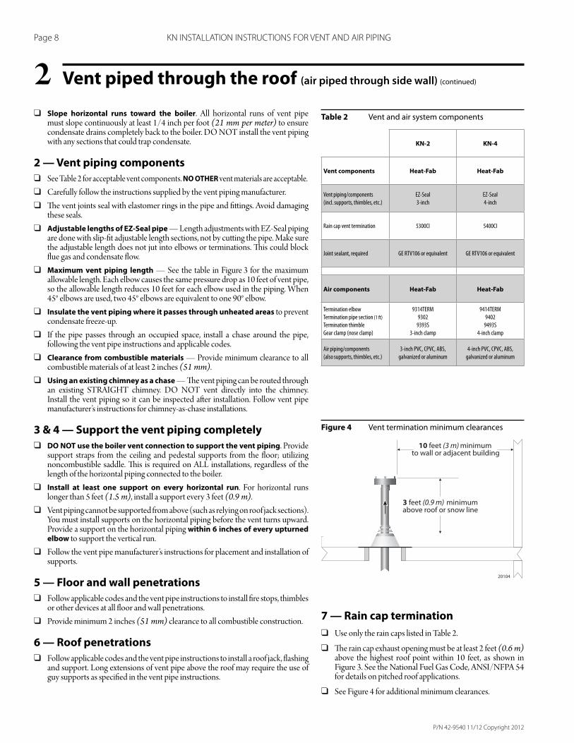
Vent piped through the roof (air piped through side wall) (continued)2Table 2 Vent and air system components
Figure 4 Vent termination minimum clearances
❑ Slope horizontal runs toward the boiler. All horizontal runs of vent pipe must slope continuously at least 1/4 inch per foot (21 mm per meter) to ensure condensate drains completely back to the boiler. DO NOT install the vent piping with any sections that could trap condensate.
2 — Vent piping components
❑ See Table 2 for acceptable vent components. NO OTHER vent materials are acceptable.
❑ Carefully follow the instructions supplied by the vent piping manufacturer.
❑ Th e vent joints seal with elastomer rings in the pipe and fi tt ings. Avoid damaging these seals.
❑ Adjustable lengths of EZ-Seal pipe — Length adjustments with EZ-Seal piping are done with slip-fi t adjustable length sections, not by cutt ing the pipe. Make sure the adjustable length does not jut into elbows or terminations. Th is could block fl ue gas and condensate fl ow.
❑ Maximum vent piping length — See the table in Figure 3 for the maximum allowable length. Each elbow causes the same pressure drop as 10 feet of vent pipe, so the allowable length reduces 10 feet for each elbow used in the piping. When 45° elbows are used, two 45° elbows are equivalent to one 90° elbow.
❑ Insulate the vent piping where it passes through unheated areas to prevent condensate freeze-up.
❑ If the pipe passes through an occupied space, install a chase around the pipe, following the vent pipe instructions and applicable codes.
❑ Clearance from combustible materials — Provide minimum clearance to all combustible materials of at least 2 inches (51 mm).
❑ Using an existing chimney as a chase — Th e vent piping can be routed through an existing STRA IGHT chimney. DO NOT vent directly into the chimney. Install the vent piping so it can be inspected aft er installation. Follow vent pipe manufacturer’s instructions for chimney-as-chase installations.
3 & 4 — Support the vent piping completely
❑ DO NOT use the boiler vent connection to support the vent piping. Provide support straps from the ceiling and pedestal supports from the fl oor; utilizing noncombustible saddle. Th is is required on ALL installations, regardless of the length of the horizontal piping connected to the boiler.
❑ Install at least one support on every horizontal run. For horizontal runs longer than 5 feet (1.5 m), install a support every 3 feet (0.9 m).
❑ Vent piping cannot be supported from above (such as relying on roof jack sections). You must install supports on the horizontal piping before the vent turns upward. Provide a support on the horizontal piping within 6 inches of every upturned elbow to support the vertical run.
❑ Follow the vent pipe manufacturer’s instructions for placement and installation of supports.
5 — Floor and wall penetrations
❑ Follow applicable codes and the vent pipe instructions to install fi re stops, thimbles or other devices at all fl oor and wall penetrations.
❑ Provide minimum 2 inches (51 mm) clearance to all combustible construction.
6 — Roof penetrations
❑ Follow applicable codes and the vent pipe instructions to install a roof jack, fl ashing and support. Long extensions of vent pipe above the roof may require the use of guy supports as specifi ed in the vent pipe instructions.
7 — Rain cap termination
❑ Use only the rain caps listed in Table 2.
❑ Th e rain cap exhaust opening must be at least 2 feet (0.6 m) above the highest roof point within 10 feet, as shown in Figure 3. See the National Fuel Gas Code, ANSI/NFPA 54 for details on pitched roof applications.
❑ See Figure 4 for additional minimum clearances.
KN-2 KN-4
Vent components Heat-Fab Heat-Fab
Vent piping/components
(incl. supports, thimbles, etc.)
EZ-Seal
3-inch
EZ-Seal
4-inch
Rain cap vent termination 5300CI 5400CI
Joint sealant, required GE RTV106 or equivalent GE RTV106 or equivalent
Air components Heat-Fab Heat-Fab
Termination elbow
Termination pipe section (1 ft)
Termination thimble
Gear clamp (nose clamp)
9314TERM
9302
9393S
3-inch clamp
9414TERM
9402
9493S
4-inch clamp
Air piping/components
(also supports, thimbles, etc.)
3-inch PVC, CPVC, ABS,
galvanized or aluminum
4-inch PVC, CPVC, ABS,
galvanized or aluminum
P/N 42-9540 11/12 Copyright 2012
Page 9 KN INSTALLATION INSTRUCTIONS FOR VENT AND AIR PIPING
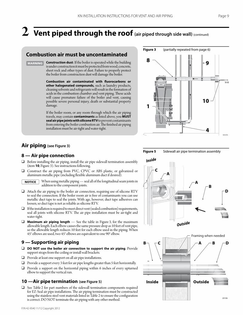
Vent piped through the roof (air piped through side wall) (continued)2Figure 3 (partially repeated from page 6)
Figure 5 Sidewall air pipe termination assembly
Combustion air must be uncontaminated
Construction dust: If the boiler is operated while the building is under construction it must be protected from wood, concrete, sheet rock and other types of dust. Failure to properly protect the boiler from construction dust will damage the boiler.
Combustion air contaminated with fl uorocarbons or other halogenated compounds, such as laundry products, cleaning solvents and refrigerants will result in the formation of acids in the combustion chamber and vent piping. Th ese acids will cause premature failure of the boiler and vent, causing possible severe personal injury, death or substantial property damage.
If the boiler room, or any room through which the air piping travels, may contain contaminants as listed above, you MUST seal air pipe joints with silicone RTV to prevent contaminants from entering the boiler combustion air. Th e fi nished air piping installation must be air-tight and water-tight.
Air piping (see Figure 3)
8 — Air pipe connection ❑ Before installing the air piping, install the air pipe sidewall termination assembly
(item 10, Figure 3). See instructions following.
❑ Construct the air piping from PVC, CPVC or ABS plastic, or galvanized or aluminum metallic pipe (including fl exible aluminum duct if desired).
When using metallic piping — seal all of the longitudinal seam joints in addition to the component joints.
❑ Att ach the air piping to the boiler air connection, requiring use of silicone RTV to seal the connection. If the boiler room air is free of contaminants you can use metallic duct tape to seal the joints. With age, however, duct tape adhesives can loosen, so duct tape is not as reliable as silicone RTV.
❑ If the installation is required to meet direct vent (sealed combustion) requirements, seal all joints with silicone RTV. Th e air pipe installation must be air-tight and water-tight.
❑ Maximum air piping length — See the table in Figure 3, for the maximum allowable length. Each elbow causes the same pressure drop as 10 feet of vent pipe, so the allowable length reduces 10 feet for each elbow used in the piping. When 45° elbows are used, two 45° elbows are equivalent to one 90° elbow.
9 — Supporting air piping ❑ DO NOT use the boiler air connection to support the air piping. Provide
support straps from the ceiling or install wall brackets.
❑ Provide at least one support on all air pipe installations.
❑ Provide a support every 3 feet for air pipe lengths greater than 5 feet horizontally.
❑ Provide a support on the horizontal piping within 6 inches of every upturned elbow to support the vertical run.
10 —Air pipe termination (see Figure 5)
❑ See Table 2 for part numbers of the sidewall termination components required for EZ-Seal air pipe installations. Th e air piping termination must be constructed using the stainless steel vent materials listed in Table 2 to ensure the confi guration is correct. DO NOT terminate the air piping with any other method.
P/N 42-9540 11/12 Copyright 2012
Page 10 KN INSTALLATION INSTRUCTIONS FOR VENT AND AIR PIPING
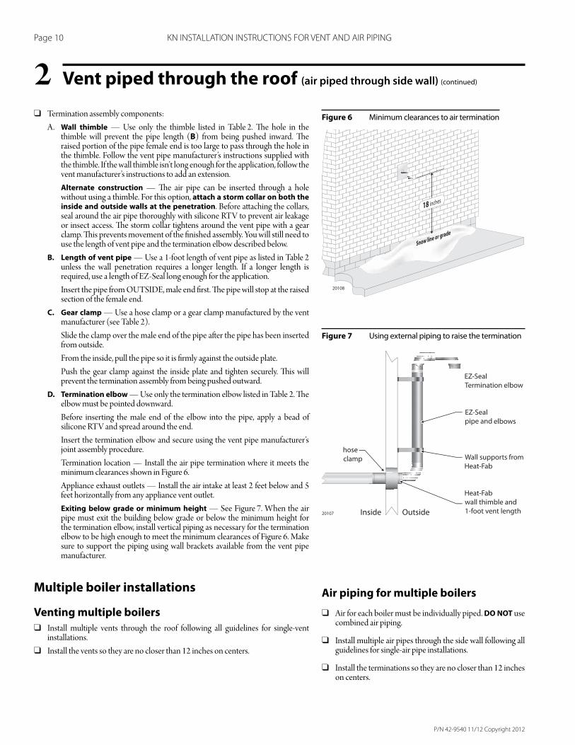
Vent piped through the roof (air piped through side wall) (continued)2Figure 6 Minimum clearances to air termination
Figure 7 Using external piping to raise the termination
❑ Termination assembly components:
A. Wall thimble — Use only the thimble listed in Table 2. Th e hole in the thimble will prevent the pipe length (B) from being pushed inward. Th e raised portion of the pipe female end is too large to pass through the hole in the thimble. Follow the vent pipe manufacturer’s instructions supplied with the thimble. If the wall thimble isn’t long enough for the application, follow the vent manufacturer’s instructions to add an extension.
Alternate construction — Th e air pipe can be inserted through a hole without using a thimble. For this option, attach a storm collar on both the inside and outside walls at the penetration. Before att aching the collars, seal around the air pipe thoroughly with silicone RTV to prevent air leakage or insect access. Th e storm collar tightens around the vent pipe with a gear clamp. Th is prevents movement of the fi nished assembly. You will still need to use the length of vent pipe and the termination elbow described below.
B. Length of vent pipe — Use a 1-foot length of vent pipe as listed in Table 2 unless the wall penetration requires a longer length. If a longer length is required, use a length of EZ-Seal long enough for the application.
Insert the pipe from OUTSIDE, male end fi rst. Th e pipe will stop at the raised section of the female end.
C. Gear clamp — Use a hose clamp or a gear clamp manufactured by the vent manufacturer (see Table 2).
Slide the clamp over the male end of the pipe aft er the pipe has been inserted from outside.
From the inside, pull the pipe so it is fi rmly against the outside plate.
Push the gear clamp against the inside plate and tighten securely. Th is will prevent the termination assembly from being pushed outward.
D. Termination elbow — Use only the termination elbow listed in Table 2. Th e elbow must be pointed downward.
Before inserting the male end of the elbow into the pipe, apply a bead of silicone RTV and spread around the end.
Insert the termination elbow and secure using the vent pipe manufacturer’s joint assembly procedure.
Termination location — Install the air pipe termination where it meets the minimum clearances shown in Figure 6.
Appliance exhaust outlets — Install the air intake at least 2 feet below and 5 feet horizontally from any appliance vent outlet.
Exiting below grade or minimum height — See Figure 7. When the air pipe must exit the building below grade or below the minimum height for the termination elbow, install vertical piping as necessary for the termination elbow to be high enough to meet the minimum clearances of Figure 6. Make sure to support the piping using wall brackets available from the vent pipe manufacturer.
Multiple boiler installations
Venting multiple boilers
❑ Install multiple vents through the roof following all guidelines for single-vent installations.
❑ Install the vents so they are no closer than 12 inches on centers.
Air piping for multiple boilers
❑ Air for each boiler must be individually piped. DO NOT use combined air piping.
❑ Install multiple air pipes through the side wall following all guidelines for single-air pipe installations.
❑ Install the terminations so they are no closer than 12 inches on centers.
P/N 42-9540 11/12 Copyright 2012
Page 11 KN INSTALLATION INSTRUCTIONS FOR VENT AND AIR PIPING
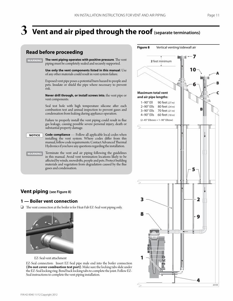
Vent and air piped through the roof (separate terminations)3Figure 8 Vertical venting/sidewall air
Read before proceeding
The vent piping operates with positive pressure. Th e vent piping must be completely sealed and securely supported.
Use only the vent components listed in this manual. Use of any other materials could result in vent system failure.
Exposed vent pipe poses a potential burn hazard to people and pets. Insulate or shield the pipe where necessary to prevent risk.
Never drill through, or install screws into, the vent pipe or vent components.
Seal test hole with high temperature silicone aft er each combustion test and annual inspection to prevent gases and condensation from leaking during appliance operation.
Failure to properly install the vent piping could result in fl ue gas leakage, causing possible severe personal injury, death or substantial property damage.
Code compliance — Follow all applicable local codes when installing the vent system. Where codes diff er from this manual, follow code requirements. Contact Advanced Th ermal Hydronics if you have any questions regarding the installation.
Terminate the vent and air piping following the guidelines in this manual. Avoid vent termination locations likely to be aff ected by winds, snowdrift s, people and pets. Protect building materials and vegetation from degradation caused by the fl ue gases and condensation.
Vent piping (see Figure 8)
1 — Boiler vent connection
❑ Th e vent connection at the boiler is for Heat-Fab EZ-Seal vent piping only.
EZ-Seal vent att achment
EZ-Seal connection: Insert EZ-Seal pipe male end into the boiler connection (Do not cover combustion test port). Make sure the locking tabs slide under the EZ-Seal locking ring. Bend back locking tabs to complete the joint. Follow EZ-Seal instructions to complete the vent piping installation.
P/N 42-9540 11/12 Copyright 2012
Page 12 KN INSTALLATION INSTRUCTIONS FOR VENT AND AIR PIPING
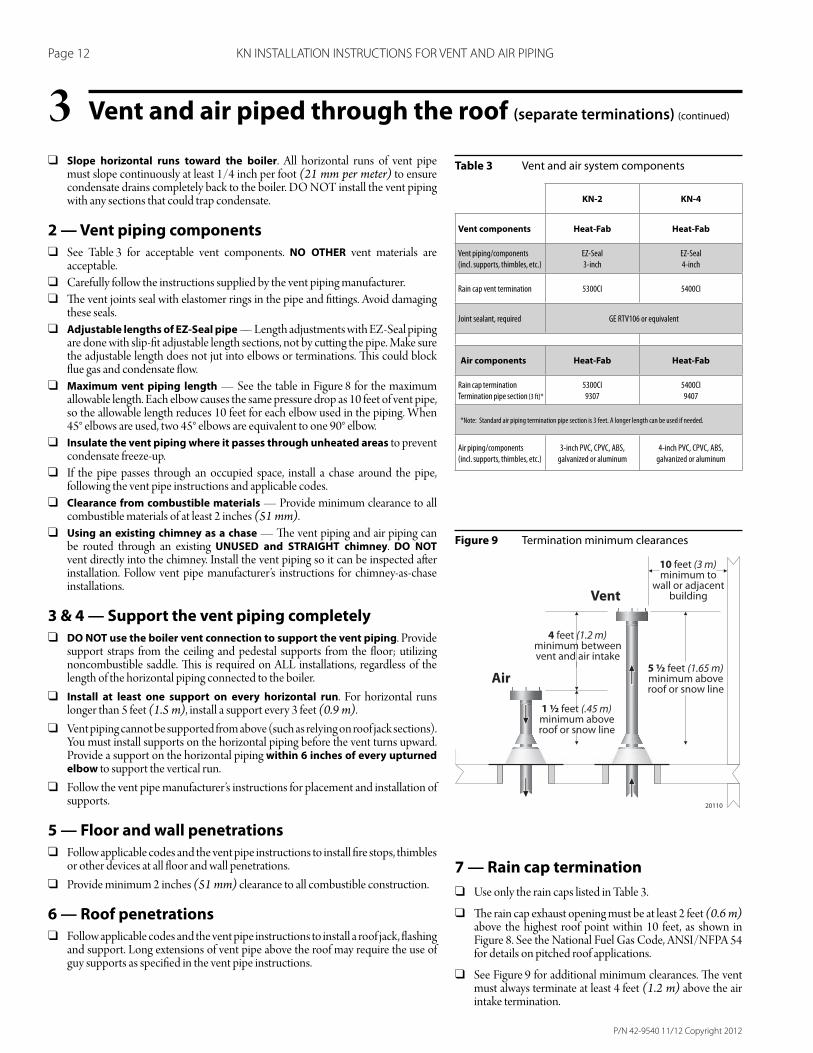
Vent and air piped through the roof (separate terminations) (continued)3Table 3 Vent and air system components
Figure 9 Termination minimum clearances
❑ Slope horizontal runs toward the boiler. All horizontal runs of vent pipe must slope continuously at least 1/4 inch per foot (21 mm per meter) to ensure condensate drains completely back to the boiler. DO NOT install the vent piping with any sections that could trap condensate.
2 — Vent piping components
❑ See Table 3 for acceptable vent components. NO OTHER vent materials are acceptable.
❑ Carefully follow the instructions supplied by the vent piping manufacturer.
❑ Th e vent joints seal with elastomer rings in the pipe and fi tt ings. Avoid damaging these seals.
❑ Adjustable lengths of EZ-Seal pipe — Length adjustments with EZ-Seal piping are done with slip-fi t adjustable length sections, not by cutt ing the pipe. Make sure the adjustable length does not jut into elbows or terminations. Th is could block fl ue gas and condensate fl ow.
❑ Maximum vent piping length — See the table in Figure 8 for the maximum allowable length. Each elbow causes the same pressure drop as 10 feet of vent pipe, so the allowable length reduces 10 feet for each elbow used in the piping. When 45° elbows are used, two 45° elbows are equivalent to one 90° elbow.
❑ Insulate the vent piping where it passes through unheated areas to prevent condensate freeze-up.
❑ If the pipe passes through an occupied space, install a chase around the pipe, following the vent pipe instructions and applicable codes.
❑ Clearance from combustible materials — Provide minimum clearance to all combustible materials of at least 2 inches (51 mm).
❑ Using an existing chimney as a chase — Th e vent piping and air piping can be routed through an existing UNUSED and STRAIGHT chimney. DO NOT vent directly into the chimney. Install the vent piping so it can be inspected aft er installation. Follow vent pipe manufacturer’s instructions for chimney-as-chase installations.
3 & 4 — Support the vent piping completely
❑ DO NOT use the boiler vent connection to support the vent piping. Provide support straps from the ceiling and pedestal supports from the fl oor; utilizing noncombustible saddle. Th is is required on ALL installations, regardless of the length of the horizontal piping connected to the boiler.
❑ Install at least one support on every horizontal run. For horizontal runs longer than 5 feet (1.5 m), install a support every 3 feet (0.9 m).
❑ Vent piping cannot be supported from above (such as relying on roof jack sections). You must install supports on the horizontal piping before the vent turns upward. Provide a support on the horizontal piping within 6 inches of every upturned elbow to support the vertical run.
❑ Follow the vent pipe manufacturer’s instructions for placement and installation of supports.
5 — Floor and wall penetrations
❑ Follow applicable codes and the vent pipe instructions to install fi re stops, thimbles or other devices at all fl oor and wall penetrations.
❑ Provide minimum 2 inches (51 mm) clearance to all combustible construction.
6 — Roof penetrations
❑ Follow applicable codes and the vent pipe instructions to install a roof jack, fl ashing and support. Long extensions of vent pipe above the roof may require the use of guy supports as specifi ed in the vent pipe instructions.
7 — Rain cap termination
❑ Use only the rain caps listed in Table 3.
❑ Th e rain cap exhaust opening must be at least 2 feet (0.6 m) above the highest roof point within 10 feet, as shown in Figure 8. See the National Fuel Gas Code, ANSI/NFPA 54 for details on pitched roof applications.
❑ See Figure 9 for additional minimum clearances. Th e vent must always terminate at least 4 feet (1.2 m) above the air intake termination.
KN-2 KN-4
Vent components Heat-Fab Heat-Fab
Vent piping/components
(incl. supports, thimbles, etc.)
EZ-Seal
3-inch
EZ-Seal
4-inch
Rain cap vent termination 5300CI 5400CI
Joint sealant, required GE RTV106 or equivalent
Air components Heat-Fab Heat-Fab
Rain cap termination
Termination pipe section (3 ft)*
5300CI
9307
5400CI
9407
*Note: Standard air piping termination pipe section is 3 feet. A longer length can be used if needed.
Air piping/components
(incl. supports, thimbles, etc.)
3-inch PVC, CPVC, ABS,
galvanized or aluminum
4-inch PVC, CPVC, ABS,
galvanized or aluminum
P/N 42-9540 11/12 Copyright 2012
Page 13 KN INSTALLATION INSTRUCTIONS FOR VENT AND AIR PIPING
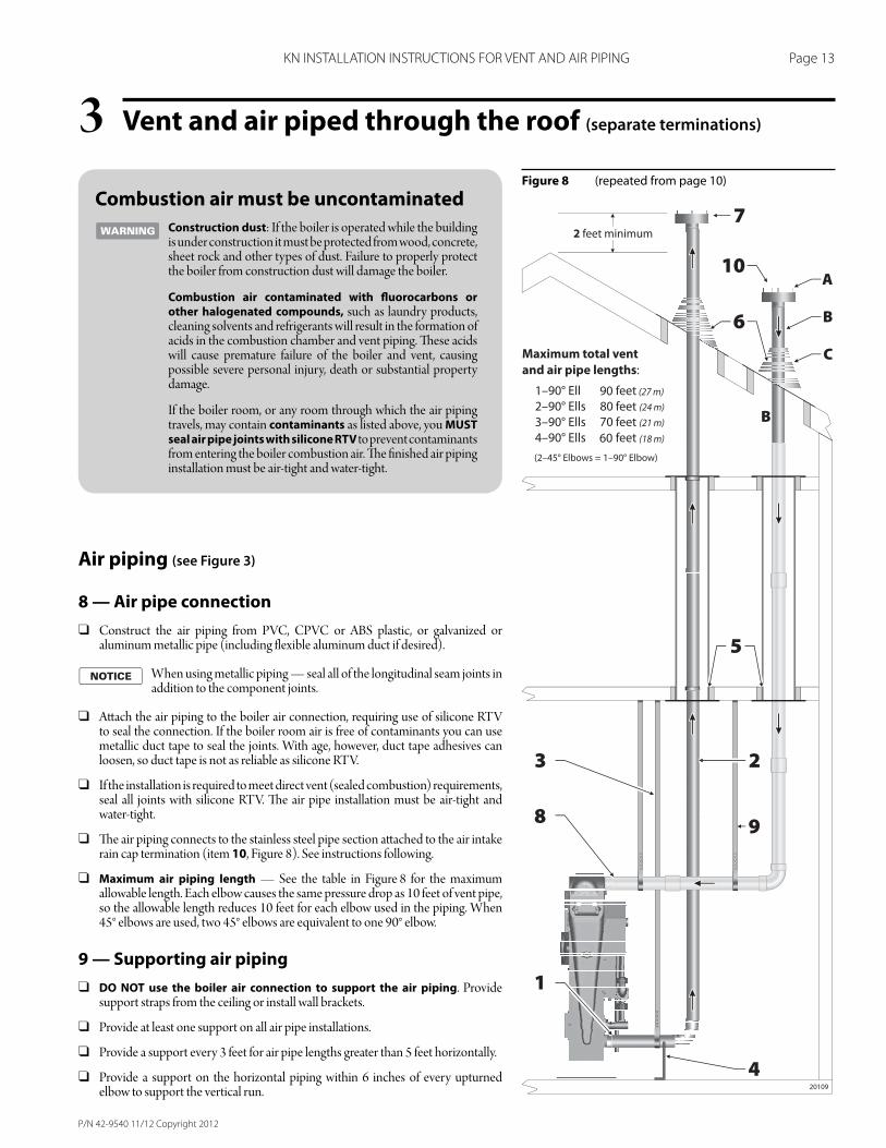
Figure 8 (repeated from page 10)
Combustion air must be uncontaminated
Construction dust: If the boiler is operated while the building is under construction it must be protected from wood, concrete, sheet rock and other types of dust. Failure to properly protect the boiler from construction dust will damage the boiler.
Combustion air contaminated with fl uorocarbons or other halogenated compounds, such as laundry products, cleaning solvents and refrigerants will result in the formation of acids in the combustion chamber and vent piping. Th ese acids will cause premature failure of the boiler and vent, causing possible severe personal injury, death or substantial property damage.
If the boiler room, or any room through which the air piping travels, may contain contaminants as listed above, you MUST seal air pipe joints with silicone RTV to prevent contaminants from entering the boiler combustion air. Th e fi nished air piping installation must be air-tight and water-tight.
Air piping (see Figure 3)
8 — Air pipe connection
❑ Construct the air piping from PVC, CPVC or ABS plastic, or galvanized or aluminum metallic pipe (including fl exible aluminum duct if desired).
When using metallic piping — seal all of the longitudinal seam joints in addition to the component joints.
❑ Att ach the air piping to the boiler air connection, requiring use of silicone RTV to seal the connection. If the boiler room air is free of contaminants you can use metallic duct tape to seal the joints. With age, however, duct tape adhesives can loosen, so duct tape is not as reliable as silicone RTV.
❑ If the installation is required to meet direct vent (sealed combustion) requirements, seal all joints with silicone RTV. Th e air pipe installation must be air-tight and water-tight.
❑ Th e air piping connects to the stainless steel pipe section att ached to the air intake rain cap termination (item 10, Figure 8). See instructions following.
❑ Maximum air piping length — See the table in Figure 8 for the maximum allowable length. Each elbow causes the same pressure drop as 10 feet of vent pipe, so the allowable length reduces 10 feet for each elbow used in the piping. When 45° elbows are used, two 45° elbows are equivalent to one 90° elbow.
9 — Supporting air piping
❑ DO NOT use the boiler air connection to support the air piping. Provide support straps from the ceiling or install wall brackets.
❑ Provide at least one support on all air pipe installations.
❑ Provide a support every 3 feet for air pipe lengths greater than 5 feet horizontally.
❑ Provide a support on the horizontal piping within 6 inches of every upturned elbow to support the vertical run.
Vent and air piped through the roof (separate terminations)3
P/N 42-9540 11/12 Copyright 2012
Page 14 KN INSTALLATION INSTRUCTIONS FOR VENT AND AIR PIPING
10 —Air pipe termination (see Figure 8)
❑ See Table 3 for part numbers of the vertical termination components required for EZ-Seal air pipe installations. Th e air piping termination must be constructed using the stainless steel vent materials listed in Table 3 to ensure the confi guration is correct. DO NOT terminate the air piping with any other method.
❑ Termination assembly components:
A. Rain cap — Use only the rain cap listed in Table 3, the same cap as used on the vent termination.
Install the rain cap so it meets the minimum clearances shown in Figure 9, page 11.
B. Length of vent pipe — Use a 3-foot length of vent pipe as listed in Table 3 unless the roof penetration requires a longer length to meet minimum clearances. If a longer length is required, use a length of EZ-Seal long enough for the application.
Att ach the air piping to the male end (bott om end) of the stainless steel pipe.
C. Roof penetration components — Use the same components as used for the vent penetration.
Multiple boiler installations
Venting multiple boilers
❑ Install multiple vents through the roof following all guidelines for single-vent installations.
❑ Install the vents so they are no closer than 12 inches on centers.
❑ Provide minimum 5 feet between the center line of any vent termination and any air intake termination.
Air piping for multiple boilers
❑ Air for each boiler must be individually piped. DO NOT use combined air piping.
❑ Install multiple air pipes through the side wall following all guidelines for single-air pipe installations.
❑ Install the terminations so they are no closer than 12 inches on centers.
❑ Provide minimum 5 feet between the center line of any vent termination and any air intake termination.
Vent and air piped through the roof (separate terminations) (continued)3
P/N 42-9540 11/12 Copyright 2012
Page 15 KN INSTALLATION INSTRUCTIONS FOR VENT AND AIR PIPING
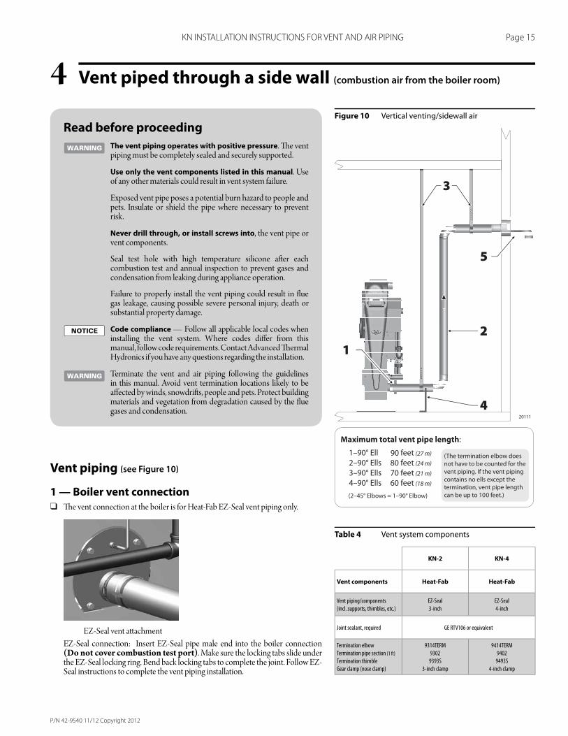
Vent piped through a side wall (combustion air from the boiler room)4Figure 10 Vertical venting/sidewall air
Table 4 Vent system components
Read before proceeding
The vent piping operates with positive pressure. Th e vent piping must be completely sealed and securely supported.
Use only the vent components listed in this manual. Use of any other materials could result in vent system failure.
Exposed vent pipe poses a potential burn hazard to people and pets. Insulate or shield the pipe where necessary to prevent risk.
Never drill through, or install screws into, the vent pipe or vent components.
Seal test hole with high temperature silicone aft er each combustion test and annual inspection to prevent gases and condensation from leaking during appliance operation.
Failure to properly install the vent piping could result in fl ue gas leakage, causing possible severe personal injury, death or substantial property damage.
Code compliance — Follow all applicable local codes when installing the vent system. Where codes diff er from this manual, follow code requirements. Contact Advanced Th ermal Hydronics if you have any questions regarding the installation.
Terminate the vent and air piping following the guidelines in this manual. Avoid vent termination locations likely to be aff ected by winds, snowdrift s, people and pets. Protect building materials and vegetation from degradation caused by the fl ue gases and condensation.
Vent piping (see Figure 10)
1 — Boiler vent connection
❑ Th e vent connection at the boiler is for Heat-Fab EZ-Seal vent piping only.
EZ-Seal vent att achment
EZ-Seal connection: Insert EZ-Seal pipe male end into the boiler connection (Do not cover combustion test port). Make sure the locking tabs slide under the EZ-Seal locking ring. Bend back locking tabs to complete the joint. Follow EZ-Seal instructions to complete the vent piping installation.
KN-2 KN-4
Vent components Heat-Fab Heat-Fab
Vent piping/components
(incl. supports, thimbles, etc.)
EZ-Seal
3-inch
EZ-Seal
4-inch
Joint sealant, required GE RTV106 or equivalent
Termination elbow
Termination pipe section (1 ft)
Termination thimble
Gear clamp (nose clamp)
9314TERM
9302
9393S
3-inch clamp
9414TERM
9402
9493S
4-inch clamp
P/N 42-9540 11/12 Copyright 2012
Page 16 KN INSTALLATION INSTRUCTIONS FOR VENT AND AIR PIPING
Vent piped through a side wall (combustion air from the boiler room) (cont.)4 ❑ Slope horizontal runs toward the boiler. All horizontal runs of vent pipe
must slope continuously at least 1/4 inch per foot (21 mm per meter) to ensure condensate drains completely back to the boiler. DO NOT install the vent piping with any sections that could trap condensate.
2 — Vent piping components
❑ See Table 4 for acceptable vent components. NO OTHER vent materials are acceptable.
❑ Carefully follow the instructions supplied by the vent piping manufacturer.
❑ Th e vent joints seal with elastomer rings in the pipe and fi tt ings. Avoid damaging these seals.
❑ Adjustable lengths of EZ-Seal pipe — Length adjustments with EZ-Seal piping are done with slip-fi t adjustable length sections, not by cutt ing the pipe. Make sure the adjustable length does not jut into elbows or terminations. Th is could block fl ue gas and condensate fl ow.
❑ Maximum vent piping length — See the table in Figure 8 for the maximum allowable length. Each elbow causes the same pressure drop as 10 feet of vent pipe, so the allowable length reduces 10 feet for each elbow used in the piping. When 45° elbows are used, two 45° elbows are equivalent to one 90° elbow.
❑ Insulate the vent piping where it passes through unheated areas to prevent condensate freeze-up. Do not insulate the within 18 inches of the termination when it passes through a combustible wall.
❑ If the pipe passes through an occupied space, install a chase around the pipe, following the vent pipe instructions and applicable codes.
❑ Clearance from combustible materials — Provide minimum clearance to all combustible materials of at least 2 inches (51 mm).
3 & 4 — Support the vent piping completely
❑ DO NOT use the boiler vent connection to support the vent piping. Provide support straps from the ceiling and pedestal supports from the fl oor; utilize noncombustible saddle. Th is is required on ALL installations, regardless of the length of the horizontal piping connected to the boiler.
❑ Install at least one support on every horizontal run. For horizontal runs longer than 5 feet (1.5 m), install a support every 3 feet (0.9 m).
❑ Vent piping cannot be supported from above (such as relying on roof jack sections). You must install supports on the horizontal piping before the vent turns upward. Provide a support on the horizontal piping within 6 inches of every upturned elbow to support the vertical run.
❑ Follow the vent pipe manufacturer’s instructions for placement and installation of supports.
❑ Follow applicable codes and the vent pipe instructions to install fi re stops, thimbles or other devices at all fl oor and wall penetrations.
❑ Provide minimum 2 inches (51 mm) clearance to all combustible construction.continued on next page
P/N 42-9540 11/12 Copyright 2012
Page 17 KN INSTALLATION INSTRUCTIONS FOR VENT AND AIR PIPING
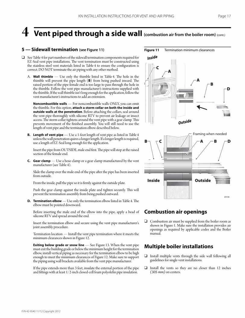
Vent piped through a side wall (combustion air from the boiler room) (cont.)4Figure 11 Termination minimum clearances5 — Sidewall termination (see Figure 11)
❑ See Table 4 for part numbers of the sidewall termination components required for EZ-Seal vent pipe installations. Th e vent termination must be constructed using the stainless steel vent materials listed in Table 4 to ensure the confi guration is correct. DO NOT terminate the air piping with any other method.
A. Wall thimble — Use only the thimble listed in Table 4. Th e hole in the thimble will prevent the pipe length (B) from being pushed inward. Th e raised portion of the pipe female end is too large to pass through the hole in the thimble. Follow the vent pipe manufacturer’s instructions supplied with the thimble. If the wall thimble isn’t long enough for the application, follow the vent manufacturer’s instructions to add an extension.
Noncombustible walls — For noncombustible walls ONLY, you can omit the thimble. For this option, attach a storm collar on both the inside and outside walls at the penetration. Before att aching the collars, seal around the vent pipe thoroughly with silicone RTV to prevent air leakage or insect access. Th e storm collar tightens around the vent pipe with a gear clamp. Th is prevents movement of the fi nished assembly. You will still need to use the length of vent pipe and the termination elbow described below.
B. Length of vent pipe — Use a 1-foot length of vent pipe as listed in Table 4 unless the wall penetration quires a longer length. If a longer length is required, use a length of EZ-Seal long enough for the application.
Insert the pipe from OUTSIDE, male end fi rst. Th e pipe will stop at the raised section of the female end.
C. Gear clamp — Use a hose clamp or a gear clamp manufactured by the vent manufacturer (see Table 4).
Slide the clamp over the male end of the pipe aft er the pipe has been inserted from outside.
From the inside, pull the pipe so it is fi rmly against the outside plate.
Push the gear clamp against the inside plate and tighten securely. Th is will prevent the termination assembly from being pushed outward.
D. Termination elbow — Use only the termination elbow listed in Table 4. Th e elbow must be pointed downward.
Before inserting the male end of the elbow into the pipe, apply a bead of silicone RTV and spread around the end.
Insert the termination elbow and secure using the vent pipe manufacturer’s joint assembly procedure.
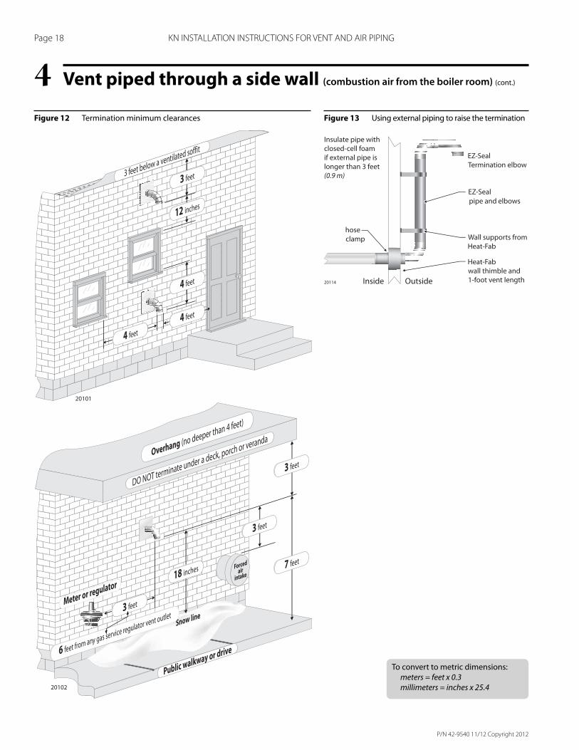
Termination location — Install the vent pipe termination where it meets the minimum clearances shown in Figure 12.
Exiting below grade or snow line — See Figure 13. When the vent pipe must exit the building grade or below the minimum height for the termination elbow, install vertical piping as necessary for the termination elbow to be high enough to meet the minimum clearances of Figure 12. Make sure to support the piping using wall brackets available from the vent pipe manufacturer.
If the pipe extends more than 3 feet, insulate the external portion of the pipe and fi tt ings with at least 1/2-inch closed-cell foam polyolefi n pipe insulation.
Combustion air openings
❑ Combustion air must be supplied from the boiler room as shown in Figure 1. Make sure the installation provides air openings as required by applicable codes and the Boiler manual.
Multiple boiler installations
❑ Install multiple vents through the side wall following all guidelines for single-vent installations.
❑ Install the vents so they are no closer than 12 inches (305 mm) on centers.
P/N 42-9540 11/12 Copyright 2012
Page 18 KN INSTALLATION INSTRUCTIONS FOR VENT AND AIR PIPING
Figure 12 Termination minimum clearances
Vent piped through a side wall (combustion air from the boiler room) (cont.)4Figure 13 Using external piping to raise the termination
To convert to metric dimensions:
meters = feet x 0.3
millimeters = inches x 25.4
P/N 42-9540 11/12 Copyright 2012
Page 19 KN INSTALLATION INSTRUCTIONS FOR VENT AND AIR PIPING
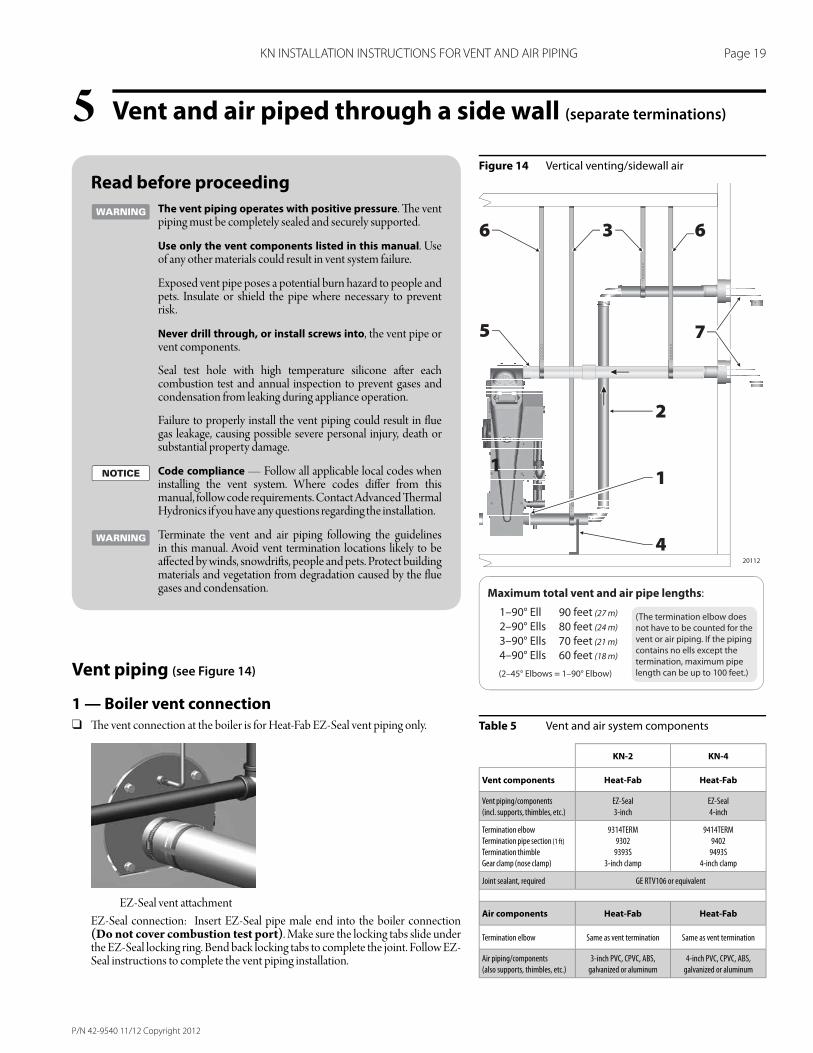
Vent and air piped through a side wall (separate terminations)5Figure 14 Vertical venting/sidewall air
Table 5 Vent and air system components
Read before proceeding
The vent piping operates with positive pressure. Th e vent piping must be completely sealed and securely supported.
Use only the vent components listed in this manual. Use of any other materials could result in vent system failure.
Exposed vent pipe poses a potential burn hazard to people and pets. Insulate or shield the pipe where necessary to prevent risk.
Never drill through, or install screws into, the vent pipe or vent components.
Seal test hole with high temperature silicone aft er each combustion test and annual inspection to prevent gases and condensation from leaking during appliance operation.
Failure to properly install the vent piping could result in fl ue gas leakage, causing possible severe personal injury, death or substantial property damage.
Code compliance — Follow all applicable local codes when installing the vent system. Where codes diff er from this manual, follow code requirements. Contact Advanced Th ermal Hydronics if you have any questions regarding the installation.
Terminate the vent and air piping following the guidelines in this manual. Avoid vent termination locations likely to be aff ected by winds, snowdrift s, people and pets. Protect building materials and vegetation from degradation caused by the fl ue gases and condensation.
Vent piping (see Figure 14)
1 — Boiler vent connection
❑ Th e vent connection at the boiler is for Heat-Fab EZ-Seal vent piping only.
EZ-Seal vent att achment
EZ-Seal connection: Insert EZ-Seal pipe male end into the boiler connection (Do not cover combustion test port). Make sure the locking tabs slide under the EZ-Seal locking ring. Bend back locking tabs to complete the joint. Follow EZ-Seal instructions to complete the vent piping installation.
KN-2 KN-4
Vent components Heat-Fab Heat-Fab
Vent piping/components
(incl. supports, thimbles, etc.)
EZ-Seal
3-inch
EZ-Seal
4-inch
Termination elbow
Termination pipe section (1 ft)
Termination thimble
Gear clamp (nose clamp)
9314TERM
9302
9393S
3-inch clamp
9414TERM
9402
9493S
4-inch clamp
Joint sealant, required GE RTV106 or equivalent
Air components Heat-Fab Heat-Fab
Termination elbow Same as vent termination Same as vent termination
Air piping/components
(also supports, thimbles, etc.)
3-inch PVC, CPVC, ABS,
galvanized or aluminum
4-inch PVC, CPVC, ABS,
galvanized or aluminum

P/N 42-9540 11/12 Copyright 2012
Page 20 KN INSTALLATION INSTRUCTIONS FOR VENT AND AIR PIPING
Vent and air piped through a side wall (separate terminations) (cont.)5 ❑ Slope horizontal runs toward the boiler. All horizontal runs of vent pipe
must slope continuously at least 1/4 inch per foot (21 mm per meter) to ensure condensate drains completely back to the boiler. DO NOT install the vent piping with any sections that could trap condensate.
2 — Vent piping components
❑ See Table 5 for acceptable vent components. NO OTHER vent materials are acceptable.
❑ Carefully follow the instructions supplied by the vent piping manufacturer.
❑ Install the sidewall vent termination before installing the vent piping.
❑ Th e vent joints seal with elastomer rings in the pipe and fi tt ings. Avoid damaging these seals.
❑ Adjustable lengths of EZ-Seal pipe — Length adjustments with EZ-Seal piping are done with slip-fi t adjustable length sections, not by cutt ing the pipe. Make sure the adjustable length does not jut into elbows or terminations. Th is could block fl ue gas and condensate fl ow.
❑ Maximum vent piping length — See the table in Figure 14 for the maximum allowable length. Each elbow causes the same pressure drop as 10 feet of vent pipe, so the allowable length reduces 10 feet for each elbow used in the piping. When 45° elbows are used, two 45° elbows are equivalent to one 90° elbow.
❑ Insulate the vent piping where it passes through unheated areas to prevent condensate freeze-up. If the vent terminates through a combustible wall, leave the last 18 inches of vent pipe uninsulated.
❑ If the pipe passes through an occupied space, install a chase around the pipe, following the vent pipe instructions and applicable codes.
❑ Clearance from combustible materials — Provide minimum clearance to all combustible materials of at least 2 inches (51 mm).
3 & 4 — Support the vent piping completely
❑ DO NOT use the boiler vent connection to support the vent piping. Provide support straps from the ceiling and pedestal supports from the fl oor; utilize noncombustible saddle. Th is is required on ALL installations, regardless of the length of the horizontal piping connected to the boiler.
❑ Install at least one support on every horizontal run. For horizontal runs longer than 5 feet (1.5 m), install a support every 3 feet (0.9 m).
❑ Vent piping cannot be supported from above (such as relying on roof jack sections). You must install supports on the horizontal piping before the vent turns upward. Provide a support on the horizontal piping within 6 inches of every upturned elbow to support the vertical run.
❑ Follow the vent pipe manufacturer’s instructions for placement and installation of supports.
❑ Follow applicable codes and the vent pipe instructions to install fi re stops, thimbles or other devices at all fl oor and wall penetrations.
❑ Provide minimum 2 inches (51 mm) clearance to all combustible construction.continued on next page
5 — Air pipe connection
❑ Before installing the air piping, install the air pipe sidewall termination assembly (item 7, Figure 14). See instructions on next page.
❑ Construct the air piping from PVC, CPVC or ABS plastic, or galvanized or aluminum metallic pipe (including fl exible aluminum duct if desired).
When using metallic piping — seal all of the longitudinal seam joints in addition to the component joints.
❑ Att ach the air piping to the boiler air connection, requiring use of silicone RTV to seal the connection. If the boiler room air is free of contaminants you can use metallic duct tape to seal the joints. With age, however, duct tape adhesives can loosen, so duct tape is not as reliable as silicone RTV.
❑ If the installation is required to meet direct vent (sealed combustion) requirements, seal all joints with silicone RTV. Th e air pipe installation must be air-tight and water-tight.
❑ Maximum air piping length — See the table in Figure 14 for the maximum allowable length. Each elbow causes the same pressure drop as 10 feet of vent pipe, so the allowable length reduces 10 feet for each elbow used in the piping. When 45° elbows are used, two 45° elbows are equivalent to one 90° elbow.
6 — Supporting air piping
❑ DO NOT use the boiler air connection to support the air piping. Provide support straps from the ceiling or install wall brackets.
❑ Provide at least one support on all air pipe installations.
❑ Provide a support every 3 feet for air pipe lengths greater than 5 feet horizontally.
❑ Provide a support on the horizontal piping within 6 inches of every upturned elbow to support the vertical run.
7 — Sidewall termination assemblies
❑ See next page.
P/N 42-9540 11/12 Copyright 2012
Page 21 KN INSTALLATION INSTRUCTIONS FOR VENT AND AIR PIPING
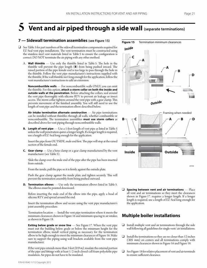
Vent and air piped through a side wall (separate terminations)5Figure 15 Termination minimum clearances7 — Sidewall termination assemblies (see Figure 15)
❑ See Table 5 for part numbers of the sidewall termination components required for EZ-Seal vent pipe installations. Th e vent termination must be constructed using the stainless steel vent materials listed in Table 5 to ensure the confi guration is correct. DO NOT terminate the air piping with any other method.
A. Wall thimble — Use only the thimble listed in Table 5. Th e hole in the thimble will prevent the pipe length (B) from being pushed inward. Th e raised portion of the pipe female end is too large to pass through the hole in the thimble. Follow the vent pipe manufacturer’s instructions supplied with the thimble. If the wall thimble isn’t long enough for the application, follow the vent manufacturer’s instructions to add an extension.
Noncombustible walls — For noncombustible walls ONLY, you can omit the thimble. For this option, attach a storm collar on both the inside and outside walls at the penetration. Before att aching the collars, seal around the vent pipe thoroughly with silicone RTV to prevent air leakage or insect access. Th e storm collar tightens around the vent pipe with a gear clamp. Th is prevents movement of the fi nished assembly. You will still need to use the length of vent pipe and the termination elbow described below.
Air intake termination alternate construction — Air pipe terminations can be installed without thimbles through all walls, whether combustible or noncombustible. Th e termination assemblies must use storm collars as described above for vent piping through noncombustible walls.
B. Length of vent pipe — Use a 1-foot length of vent pipe as listed in Table 5 unless the wall penetration quires a longer length. If a longer length is required, use a length of EZ-Seal long enough for the application.
Insert the pipe from OUTSIDE, male end fi rst. Th e pipe will stop at the raised section of the female end.
C. Gear clamp — Use a hose clamp or a gear clamp manufactured by the vent manufacturer (see Table 5).
Slide the clamp over the male end of the pipe aft er the pipe has been inserted from outside.
From the inside, pull the pipe so it is fi rmly against the outside plate.
Push the gear clamp against the inside plate and tighten securely. Th is will prevent the termination assembly from being pushed outward.
D. Termination elbows — Use only the termination elbows listed in Table 5. Th e elbows must be pointed downward.
Before inserting the male end of the elbow into the pipe, apply a bead of silicone RTV and spread around the end.
Insert the termination elbow and secure using the vent pipe manufacturer’s joint assembly procedure.
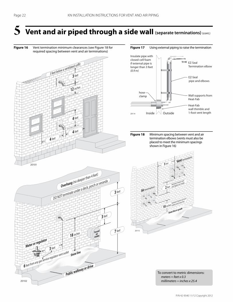
Termination location — Install the vent pipe termination where it meets the minimum clearances shown in Figure 16 and minimum spacing to air intakes as shown in Figure 18.
Exiting below grade or snow line — See Figure 17. When the vent pipe must exit the building below grade or below the minimum height for the termination elbow, install vertical piping as necessary for the termination elbow to be high enough to meet the minimum clearances of Figure 16. Make sure to support the piping using wall brackets available from the vent pipe manufacturer.
If the vent pipe extends more than 3 feet (0.9 m), insulate the external portion of the pipe and fi tt ings with at least 1/2-inch closed-cell foam polyolefi n pipe insulation. Air pipes do not have to be insulated.
❑ Spacing between vent and air terminations — Place all vent and air terminations so they meet the clearances shown in Figure 17. requires a longer length. If a longer length is required, use a length of EZ-Seal long enough for the application.
Multiple boiler installations
❑ Install multiple vent and air terminations through the side wall following all guidelines for single-vent/air installations.
❑ Install the terminations so they are no closer than 12 inches (305 mm) on centers and all terminations comply with minimum clearances shown in Figure 16 and Figure 18.
❑ See Figure 18 for relative placement of vent and air terminals to ensure suffi cient clearance.
P/N 42-9540 11/12 Copyright 2012
Page 22 KN INSTALLATION INSTRUCTIONS FOR VENT AND AIR PIPING
Vent and air piped through a side wall (separate terminations) (cont.)5Figure 16 Vent termination minimum clearances (see Figure 18 for
required spacing between vent and air terminations)Figure 17 Using external piping to raise the termination
Figure 18 Minimum spacing between vent and air termination elbows (vents must also be placed to meet the minimum spacings shown in Figure 16)
To convert to metric dimensions:
meters = feet x 0.3
millimeters = inches x 25.4
P/N 42-9540 11/12 Copyright 2012
Page 23 KN INSTALLATION INSTRUCTIONS FOR VENT AND AIR PIPING
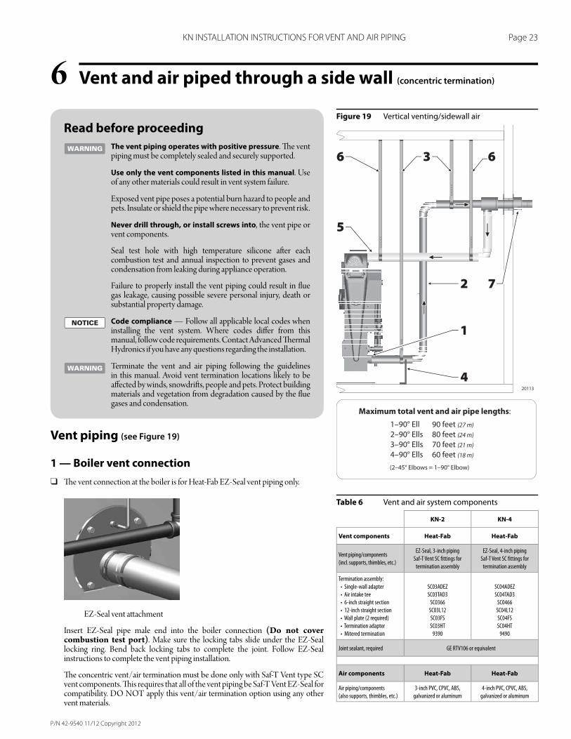
Vent and air piped through a side wall (concentric termination)6Figure 19 Vertical venting/sidewall air
Table 6 Vent and air system components
Read before proceeding
The vent piping operates with positive pressure. Th e vent piping must be completely sealed and securely supported.
Use only the vent components listed in this manual. Use of any other materials could result in vent system failure.
Exposed vent pipe poses a potential burn hazard to people and pets. Insulate or shield the pipe where necessary to prevent risk.
Never drill through, or install screws into, the vent pipe or vent components.
Seal test hole with high temperature silicone aft er each combustion test and annual inspection to prevent gases and condensation from leaking during appliance operation.
Failure to properly install the vent piping could result in fl ue gas leakage, causing possible severe personal injury, death or substantial property damage.
Code compliance — Follow all applicable local codes when installing the vent system. Where codes diff er from this manual, follow code requirements. Contact Advanced Th ermal Hydronics if you have any questions regarding the installation.
Terminate the vent and air piping following the guidelines in this manual. Avoid vent termination locations likely to be aff ected by winds, snowdrift s, people and pets. Protect building materials and vegetation from degradation caused by the fl ue gases and condensation.
Vent piping (see Figure 19)
1 — Boiler vent connection
❑ Th e vent connection at the boiler is for Heat-Fab EZ-Seal vent piping only.
EZ-Seal vent att achment
Insert EZ-Seal pipe male end into the boiler connection (Do not cover combustion test port). Make sure the locking tabs slide under the EZ-Seal locking ring. Bend back locking tabs to complete the joint. Follow EZ-Seal instructions to complete the vent piping installation.
Th e concentric vent/air termination must be done only with Saf-T Vent type SC vent components. Th is requires that all of the vent piping be Saf-T Vent EZ-Seal for compatibility. DO NOT apply this vent/air termination option using any other vent materials.
KN-2 KN-4
Vent components Heat-Fab Heat-Fab
Vent piping/components
(incl. supports, thimbles, etc.)
EZ-Seal, 3-inch piping
Saf-T Vent SC fi ttings for
termination assembly
EZ-Seal, 4-inch piping
Saf-T Vent SC fi ttings for
termination assembly
Termination assembly:
• Single-wall adapter
• Air intake tee
• 6-inch straight section
• 12-inch straight section
• Wall plate (2 required)
• Termination adapter
• Mitered termination
SC03ADEZ
SC03TAD3
SC0366
SC03L12
SC03FS
SC03HT
9390
SC04ADEZ
SC04TAD3
SC0466
SC04L12
SC04FS
SC04HT
9490
Joint sealant, required GE RTV106 or equivalent
Air components Heat-Fab Heat-Fab
Air piping/components
(also supports, thimbles, etc.)
3-inch PVC, CPVC, ABS,
galvanized or aluminum
4-inch PVC, CPVC, ABS,
galvanized or aluminum
P/N 42-9540 11/12 Copyright 2012
Page 24 KN INSTALLATION INSTRUCTIONS FOR VENT AND AIR PIPING
Vent and air piped through a side wall (concentric termination) (cont.)6 ❑ Slope horizontal runs toward the boiler. All horizontal runs of vent pipe
must slope continuously at least 1/4 inch per foot (21 mm per meter) to ensure condensate drains completely back to the boiler. DO NOT install the vent piping with any sections that could trap condensate.
2 — Vent piping components
❑ See Table 6 for acceptable vent components. NO OTHER vent materials are acceptable.
❑ Carefully follow the instructions supplied by the vent piping manufacturer.
❑ Install the sidewall termination/concentric vent-air assembly (item 7, Figure 19) before installing the vent or air piping.
❑ Th e vent joints seal with elastomer rings in the pipe and fi tt ings. Avoid damaging these seals.
❑ Adjustable lengths of EZ-Seal pipe — Length adjustments with EZ-Seal piping are done with slip-fi t adjustable length sections, not by cutt ing the pipe. Make sure the adjustable length does not jut into elbows or terminations. Th is could block fl ue gas and condensate fl ow.
❑ Maximum vent piping length — See the table in Figure 19 for the maximum allowable length. Each elbow causes the same pressure drop as 10 feet of vent pipe, so the allowable length reduces 10 feet for each elbow used in the piping. When 45° elbows are used, two 45° elbows are equivalent to one 90° elbow.
❑ Insulate the vent piping where it passes through unheated areas to prevent condensate freeze-up.
❑ If the pipe passes through an occupied space, install a chase around the pipe, following the vent pipe instructions and applicable codes.
❑ Clearance from combustible materials — Provide minimum clearance to all combustible materials of at least 2 inches (51 mm).
3 & 4 — Support the vent piping completely
❑ DO NOT use the boiler vent connection to support the vent piping. Provide support straps from the ceiling and pedestal supports from the fl oor; utilize noncombustible saddle. Th is is required on ALL installations, regardless of the length of the horizontal piping connected to the boiler.
❑ Install at least one support on every horizontal run. For horizontal runs longer than 5 feet (1.5 m), install a support every 3 feet (0.9 m).
❑ Vent piping cannot be supported from above (such as relying on roof jack sections). You must install supports on the horizontal piping before the vent turns upward. Provide a support on the horizontal piping within 6 inches of every upturned elbow to support the vertical run.
❑ Follow the vent pipe manufacturer’s instructions for placement and installation of supports.
❑ Follow applicable codes and the vent pipe instructions to install fi re stops, thimbles or other devices at all fl oor and wall penetrations.
❑ Provide minimum 2 inches (51 mm) clearance to all combustible construction.continued on next page
5 — Air pipe connection
❑ Before installing the air piping, install the air pipe sidewall termination assembly (item 7, Figure 19). See instructions on next page.
❑ Construct the air piping from PVC, CPVC or ABS plastic, galvanized or aluminum metallic pipe (including fl exible aluminum duct if desired).
When using metallic piping — seal all of the longitudinal seam joints in addition to the component joints.
❑ Att ach the air piping to the boiler air connection, requiring use of silicone RTV to seal the connection. If the boiler room air is free of contaminants you can use metallic duct tape to seal the joints. With age, however, duct tape adhesives can loosen, so duct tape is not as reliable as silicone RTV.
❑ If the installation is required to meet direct vent (sealed combustion) requirements, seal all joints with silicone RTV. Th e air pipe installation must be air-tight and water-tight.
❑ Maximum air piping length — See the table in Figure 19 for the maximum allowable length. Each elbow causes the same pressure drop as 10 feet of vent pipe, so the allowable length reduces 10 feet for each elbow used in the piping. When 45° elbows are used, two 45° elbows are equivalent to one 90° elbow.
6 — Supporting air piping
❑ DO NOT use the boiler air connection to support the air piping. Provide support straps from the ceiling or install wall brackets.
❑ Provide at least one support on all air pipe installations.
❑ Provide a support every 3 feet for air pipe lengths greater than 5 feet horizontally.
❑ Provide a support on the horizontal piping within 6 inches of every upturned elbow to support the vertical run.
7 — Sidewall termination/concentric
vent-air assembly
❑ See next page.
P/N 42-9540 11/12 Copyright 2012
Page 25 KN INSTALLATION INSTRUCTIONS FOR VENT AND AIR PIPING
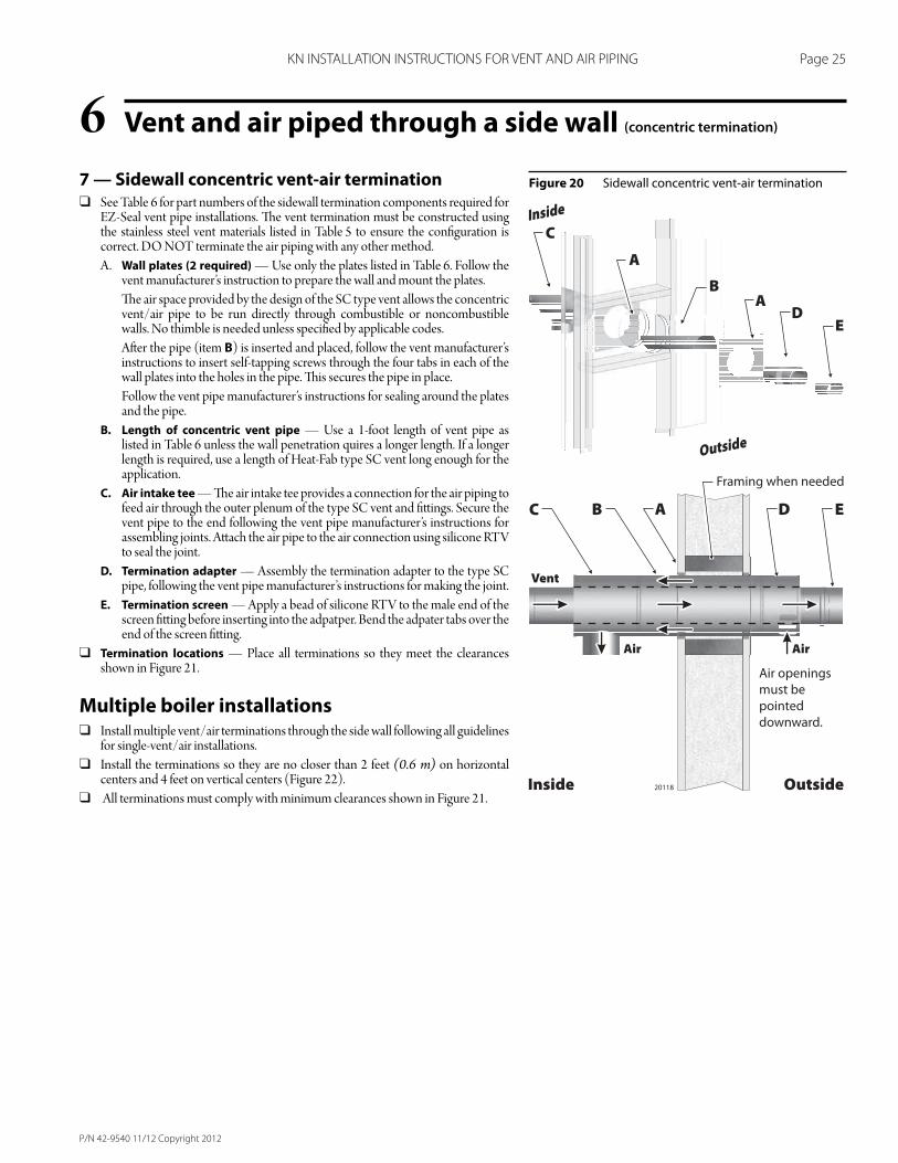
Vent and air piped through a side wall (concentric termination)67 — Sidewall concentric vent-air termination
❑ See Table 6 for part numbers of the sidewall termination components required for EZ-Seal vent pipe installations. Th e vent termination must be constructed using the stainless steel vent materials listed in Table 5 to ensure the confi guration is correct. DO NOT terminate the air piping with any other method.
A. Wall plates (2 required) — Use only the plates listed in Table 6. Follow the vent manufacturer’s instruction to prepare the wall and mount the plates.
Th e air space provided by the design of the SC type vent allows the concentric vent/air pipe to be run directly through combustible or noncombustible walls. No thimble is needed unless specifi ed by applicable codes.
Aft er the pipe (item B) is inserted and placed, follow the vent manufacturer’s instructions to insert self-tapping screws through the four tabs in each of the wall plates into the holes in the pipe. Th is secures the pipe in place.
Follow the vent pipe manufacturer’s instructions for sealing around the plates and the pipe.
B. Length of concentric vent pipe — Use a 1-foot length of vent pipe as listed in Table 6 unless the wall penetration quires a longer length. If a longer length is required, use a length of Heat-Fab type SC vent long enough for the application.
C. Air intake tee — Th e air intake tee provides a connection for the air piping to feed air through the outer plenum of the type SC vent and fi tt ings. Secure the vent pipe to the end following the vent pipe manufacturer’s instructions for assembling joints. Att ach the air pipe to the air connection using silicone RTV to seal the joint.
D. Termination adapter — Assembly the termination adapter to the type SC pipe, following the vent pipe manufacturer’s instructions for making the joint.
E. Termination screen — Apply a bead of silicone RTV to the male end of the screen fi tt ing before inserting into the adpatper. Bend the adpater tabs over the end of the screen fi tt ing.
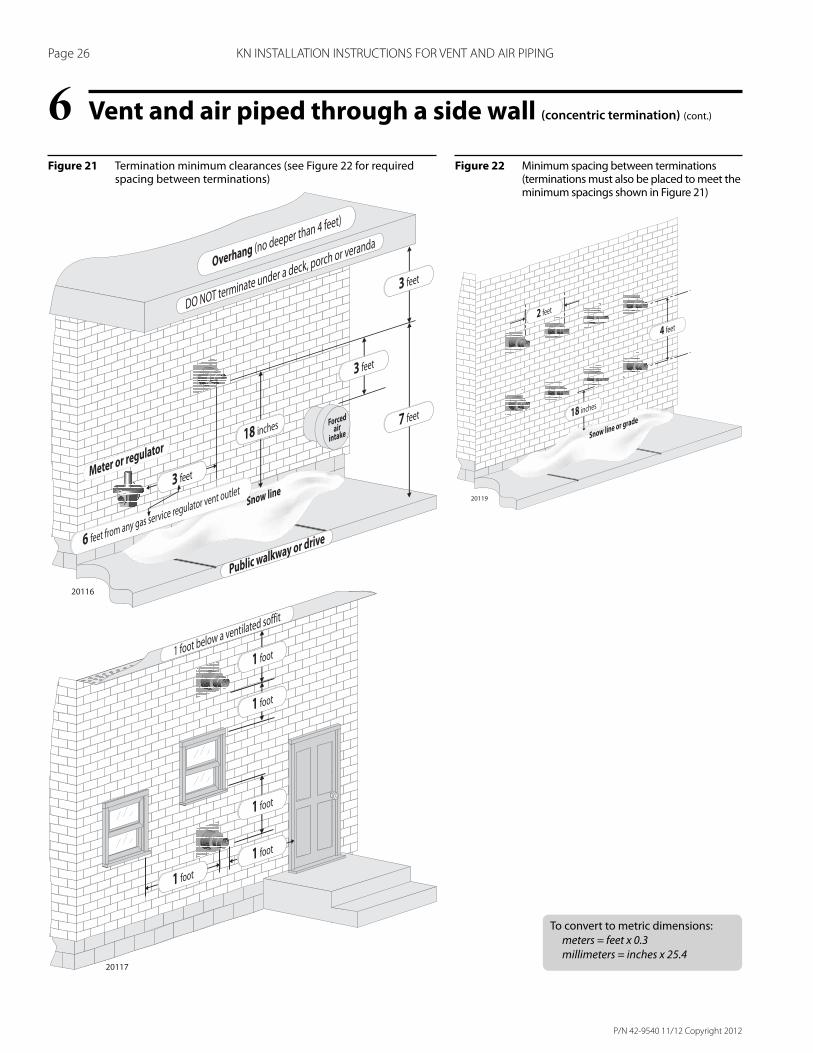
❑ Termination locations — Place all terminations so they meet the clearances shown in Figure 21.
Multiple boiler installations ❑ Install multiple vent/air terminations through the side wall following all guidelines
for single-vent/air installations.
❑ Install the terminations so they are no closer than 2 feet (0.6 m) on horizontal centers and 4 feet on vertical centers (Figure 22).
❑ All terminations must comply with minimum clearances shown in Figure 21.
Figure 20 Sidewall concentric vent-air termination
P/N 42-9540 11/12 Copyright 2012
Page 26 KN INSTALLATION INSTRUCTIONS FOR VENT AND AIR PIPING
Vent and air piped through a side wall (concentric termination) (cont.)6Figure 21 Termination minimum clearances (see Figure 22 for required
spacing between terminations)Figure 22 Minimum spacing between terminations
(terminations must also be placed to meet the minimum spacings shown in Figure 21)
To convert to metric dimensions:
meters = feet x 0.3
millimeters = inches x 25.4
P/N 42-9540 11/12 Copyright 2012
Page 27 KN INSTALLATION INSTRUCTIONS FOR VENT AND AIR PIPING
7

IN UNITED STATES: 260 NORTH ELM ST. • WESTFIELD, MA 01085 • (413) 564-5515 • FAX (413) 568-9613IN CANADA: 7555 TRANMERE DRIVE • MISSISSAUGA, ONT. L5S 1L4 • (905) 670-5888 • FAX (905) 670-5782
www.knseries.com