Embed Size (px)
Citation preview
7/27/2019 Hydrotest of pipeline.pdf
http://slidepdf.com/reader/full/hydrotest-of-pipelinepdf 1/2
HYDROSTATIC TESTING PROCEDURE 02250-1
SD P
133200,
SECTION 02250
HYDROSTATIC TESTING PROCEDURE
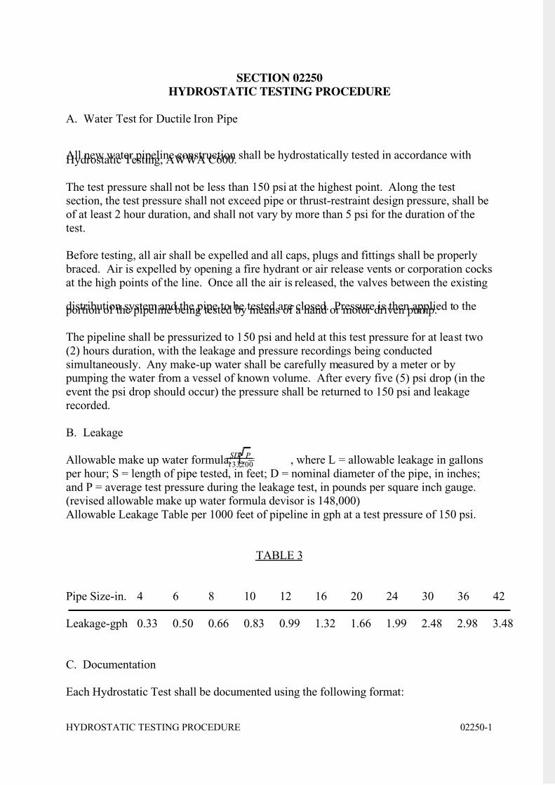
A. Water Test for Ductile Iron Pipe
All new water pipeline construction shall be hydrostatically tested in accordance withHydrostatic Testing, AWWA C600.
The test pressure shall not be less than 150 psi at the highest point. Along the testsection, the test pressure shall not exceed pipe or thrust-restraint design pressure, shall be
of at least 2 hour duration, and shall not vary by more than 5 psi for the duration of the
test.
Before testing, all air shall be expelled and all caps, plugs and fittings shall be properly
braced. Air is expelled by opening a fire hydrant or air release vents or corporation cocks
at the high points of the line. Once all the air is released, the valves between the existing
distribution system and the pipe to be tested are closed. Pressure is then applied to the portion of the pipeline being tested by means of a hand or motor driven pump.
The pipeline shall be pressurized to 150 psi and held at this test pressure for at least two
(2) hours duration, with the leakage and pressure recordings being conducted
simultaneously. Any make-up water shall be carefully measured by a meter or by pumping the water from a vessel of known volume. After every five (5) psi drop (in the
event the psi drop should occur) the pressure shall be returned to 150 psi and leakage
recorded.
B. Leakage
Allowable make up water formula: L = , where L = allowable leakage in gallons
per hour; S = length of pipe tested, in feet; D = nominal diameter of the pipe, in inches;
and P = average test pressure during the leakage test, in pounds per square inch gauge.(revised allowable make up water formula devisor is 148,000)
Allowable Leakage Table per 1000 feet of pipeline in gph at a test pressure of 150 psi.
TABLE 3
Pipe Size-in. 4 6 8 10 12 16 20 24 30 36 42
Leakage-gph 0.33 0.50 0.66 0.83 0.99 1.32 1.66 1.99 2.48 2.98 3.48
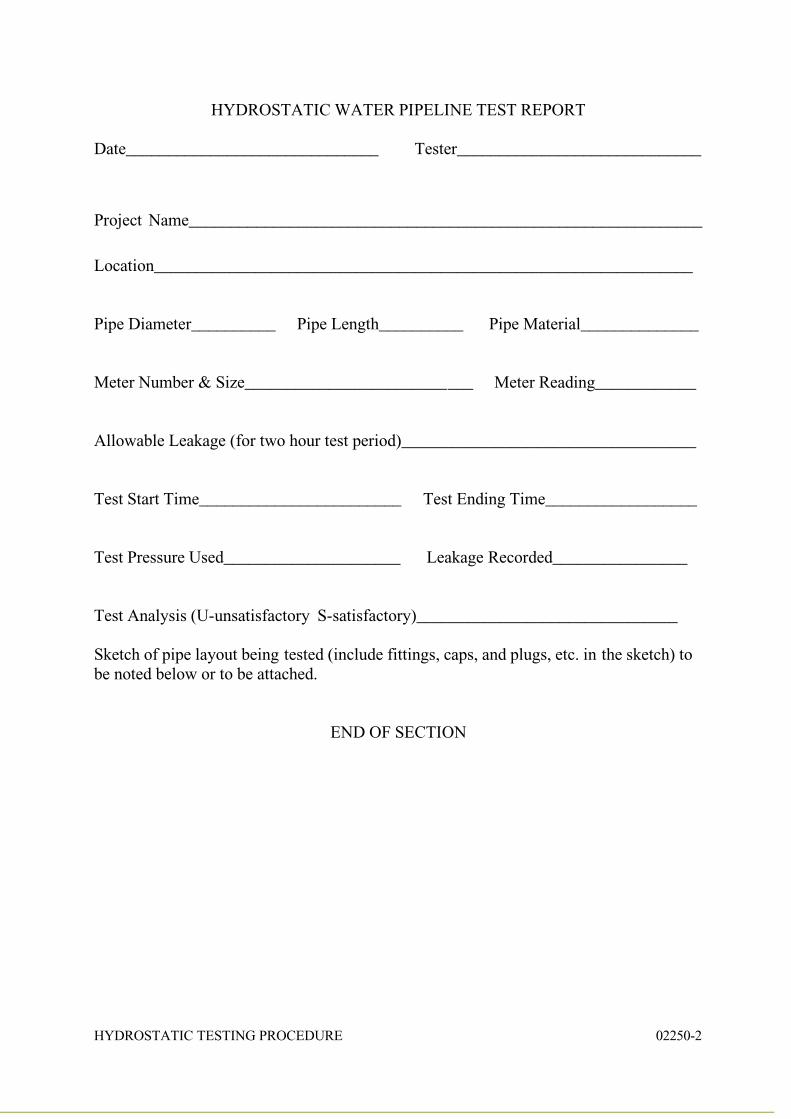
C. Documentation
Each Hydrostatic Test shall be documented using the following format:
7/27/2019 Hydrotest of pipeline.pdf
http://slidepdf.com/reader/full/hydrotest-of-pipelinepdf 2/2
HYDROSTATIC TESTING PROCEDURE 02250-2
HYDROSTATIC WATER PIPELINE TEST REPORT
Date______________________________ Tester_____________________________
Project Name_____________________________________________________________
Location________________________________________________________________
Pipe Diameter__________ Pipe Length__________ Pipe Material______________
Meter Number & Size___________________________ Meter Reading____________
Allowable Leakage (for two hour test period)___________________________________
Test Start Time________________________ Test Ending Time__________________
Test Pressure Used_____________________ Leakage Recorded________________
Test Analysis (U-unsatisfactory S-satisfactory)_______________________________
Sketch of pipe layout being tested (include fittings, caps, and plugs, etc. in the sketch) to
be noted below or to be attached.
END OF SECTION