Embed Size (px)
Citation preview
8/4/2019 API Hydrotest
http://slidepdf.com/reader/full/api-hydrotest 1/9
All welds shall be tested using the methods below as a minimum in
ensuring that the bottom and all other joints are leak free.
MECHANICAL STORAGE TANK TESTING PROCEDURE
1. Bottom & Annular Plates:
Upon completion of welding of the tank bottom, the bottom welds and
plates shall be examined visually for any potential defects
and leaks. Particular attention shall apply to areas such as sumps, dents,
gouges, three-plate laps, bottom plate breakdowns, arc-strikes, temporary
attachment removal areas, and welding lead arc bums.
a) Visual Method
b) Vacuum Box Testc) Tracer Gas Test
2. Shell Plates (Hydrostatic Testing)
Soil data and settlement and stabiiity calculations shall be available before
the tank is tested. The tank bottom profile shall be measured and recorded
before starting to fill the tank.
Method 1: ~is in four (4) stages as summarized below
After completion of the roof, the shell shall be filled with fresh water (the
required water quality shall be agreed by the COMPANy) in either of thefollowing Hydrostatic methods.
• Tank shall be filled from half to two-third of the final filling height
between 4 and 15 hrs and be monitored for 12 hrs as above.
• Tank shall be filled to half of the final filling height at the maximum
filling rate (dependent on the subsoil conditions and settlement
behavior during hydro testing) between (4hrs to 15hrs) and the
foundation shall be allowed to equilibrate, consolidate and be
monitored for 12 hrs. Measurement of the tank shell settlements
should be taken from at least 8 points evenly spaced around the
circumference at a distance of 12 meters maximum.
• Tank shall be filled from two-third to four-fifth of the final filling height
between 4 and 15 hrs and be monitored for 24 hrs as above.
8/4/2019 API Hydrotest
http://slidepdf.com/reader/full/api-hydrotest 2/9
The tank shall be filled from four-fifth to the final filling height betwe
4 and 14 hrs and be monitored for four (4) more days.
2: -
If water is available for testing the she", the tank. shall be filled w
ater as follows:-
To the maximum design liquid level, H ;
Fora tank with a tight roof, to 50 mm (2 in.) above the weld connect
the roof plate or compression bar to the top angle or shell;
To a level lower than that specified in Sub-item 1 or 2 when restricte
by overflows, an internal floating roof, or other freeboard by agreem
between the Purchaser and the Manufacturer,
To a level of seawater producing a bottom of shell hoop stress equa
that produced by a full-height fresh water test.
The tank shall be inspected frequently during the filling operation
and any welded joints above the test-water level shall be examined.
This test shall be.conducted before permanent external piping is
connected to the tank. After completion of the hydro-test, only non-
structural small attachments may be welded to the tank.
If sufficient water to fill the tank is not available, the tank may be
tested by
Painting all of the joints on the inside with a highly penetrating oil, s
as automobile spring oil, and carefully examining the outside of the
joints for leakage;
Applying vacuum to either side of the joints or applying internal airpressure and carefully examining the joints for leaka98.
Hydrostatic Testing Requirements
This hydrostatic test of the tank shall be conducted before permane
xternal piping is connected to the tank. Attachments to the shell locate
t least 1 m (3 ft) above the water level, and roof appurtenances may b
elded during the filling of the tank. After completion of the hydro-test,
nly non-structural small attachments may be welded to the tank. Any
8/4/2019 API Hydrotest
http://slidepdf.com/reader/full/api-hydrotest 3/9
g) Checking the wind girders for proper drainage during or following the
hydro-test. If water is retained, additional drainage shall be provided
subject to the Purchaser's approval.
• using any combination of the methods stipulated above.
The Manufacturer shall be responsible for the following :-
a) Preparing the tank for testing. This shall include removal of all trash,
debris, grease, oil, weld scale, weld spatter, and any other foreign matter
from the interior and the roof(s) of the tank.
b) Fumishing, laying, and removing all lines from the water source tie-in
location and to the water disposal point.
c) Filling and emptying the tank.
d) Cleaning, rinsing, drying, or other prescribed activity (if specified on the
Data sheet).
e) Tak,ing settlement measurements (unless explicitly waived by the
Purchaser on the Data Sheet).
f) Fumishing all other test materials and facilities, including blinds, bolting,
and gaskets.
3. Emptying Of The Tank After The Hydrostatic Test
Before the test water is pumped or drained from the tank, adequate
measures shall be taken to avoid a vacuum condition inside the tank. All
roof vents and manholes shall be open.
4. Measurement Of Tank Bottom Profile After The Hydrostatic Test
After the test, about 30 cm of water should be left inside the tank to ensure
that tank bottom is in contact with its foundation profile.
The tank bottom profile shall then be measured. The measured values
shall be verified against the settlement predictions and recorded in the
tank maintenance file.
8/4/2019 API Hydrotest
http://slidepdf.com/reader/full/api-hydrotest 4/9
The following safety precautions shall be taken:
5. Filling Rate (Products) After Hydrostatic Testing
In the event of poor settlement results during hydrostatic testing, a
geotechnical I foundation engineer shall attend to the case prior to the first
operational fi.lling.
- 6. Roofs Plates
• The roof shall be tested by pumping air under the roof plates while the
tank is still full of water. The influence of sudden barometric changesand possible condensation during the night shall be considered.
• Tank roofs shall be tested to a pressure of 7.5 mbar (qa), For the
detection of leaks, soap suds or similar substance shall be applied to
aU joints, Alternatively, the roof weld seams may be tested by the
vacuum box method.
7. Repair Of Lea.ks
All leaks detected during testing shall be repaired to the satisfaction of the
COMPANY by welding. For leaking shell seams, bottom-to-shell welds,
annular plate welds and bottom plate welds, the defective area shall be
cut out and repaired by welding.
Repairs in shell seams shall be performed with the test water level at 350
mm below the point being repaired.
8. RETESTING
After all defects have been repaired the repaired welds shall be re-
inspected by the methods previously described above.
9. SAFETY P'RECAUTIONS
• A product connection shall not be made to any tank for any purpose
until the tank is accepted to be filled with product by the COMPANY.
• Roof manholes shall be open while filling or ernptyinq a fixed roof tank
for test purposes, so that the tank is not damaged by excessive
vacuum or pressure loading.
8/4/2019 API Hydrotest
http://slidepdf.com/reader/full/api-hydrotest 5/9
lttlELOEO STEEL TANKS FOR OIL STORAGE
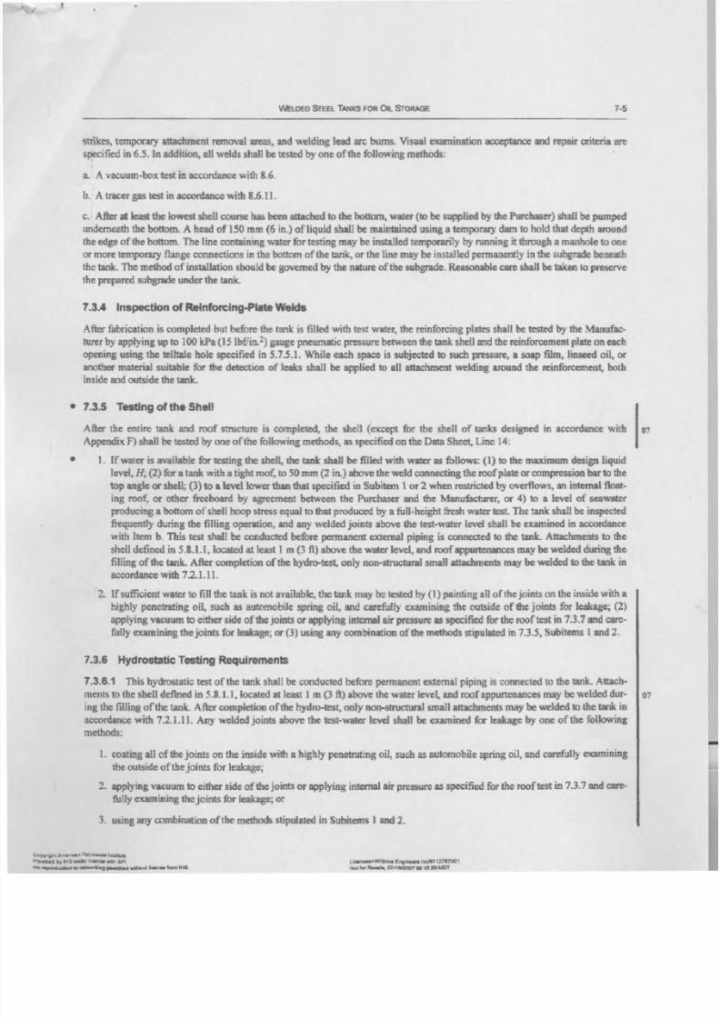
s tn_kes . tem porary attach men t rem ov al areas, a nd w eldin g lea d arc bu ms. V isual exa mina tio n acc eptan ce and repair criteria are
s pe cif ie d in 6 .5 . In a dd itio n, a ll w eld s s ha ll b e te ste d by o ne o f th e fo llo win g m eth od s:
a. - A v ac uum-b ox te st in a cc ord an ce w ith 8 .6 .
b ., A t ra ce r g as t e s t i n a cc or da nc e w it h &.6.11.
c .•After at least the l ow e st s he ll c ou rs e h as b ee n a tt ac he d to t he b ot tom , w a te r (to be supplied hy th e P urc ha se r) s ha ll b e p um pe d
underneath the bottom . A head of 1 50 m m (6 in .) of liquid shall be m aintained using a tem porary dam to h old th at d ep th a ro un d
th e e dg e o f th e b otto m. T he lin e c on ta in in g w ate r fo r te stin g m ay b e in sta lle d te mp ora rily b y ru nn in g it thro ugh a m anh ole to o ne
o r mo re t emp or ar y f la ng e c on ne ct io ns in th e bo ttom o f th e tank, o r th e lin e m ay b e in sta lle d p erm an en tly int he s ub gr ad e b en ea th
th e ta nk . T he m eth od o f in sta lla tio n s ho uld b e g ov er ne d b y the n atu re o fth e s ub gr ad e. R ea so na ble c are s ha ll be t ak en t o p re se rv e
th e p re pa re d s ub gra de u nd er th e ta nk .
7.3.4 Inspection of Reinforeing-Plate Welds
A fte r fa br ic atio n is c om ple te d b ut b efo re th e tank is fille d w ith te st w ate r, th e r ein fo rc in g p la te s sh all b e te ste d by the Manufac-
tu re r b y a pp ly in g u p to 1 00 k Pa ( 15 I b£ 'i n.2) g au ge p ne um atic p re ss ure b etw ee n th e tank s he lf a nd t he r ei nf or cem en t p la te o n e ac h
o pe nin g u sin g th e te llta le h ole s pe cifie d in 5 .7 .5 ..1 . 'W h ile e ac h s pa ce is s ub je cte d to su ch p re ssu re , a so ap film, lin se ed o il, o rano the r m aterial su itable for th e detectio n of lea ks sh all be a pp lie d to a ll a tta chme nt w eld in g a ro un d th e r ein fo rc em en t, both
i ns id e a nd o ut si de t he taak .
• 7.3.5 Testing of the Shell
A fl:e r th e e ntire ta nk and roof structure is com pleted, the shell (except for the shell of tanks designed in accordance w ith
A pp en dix F ) sh all be tested b y on e o f th e follo wing m eth od s, as sp ecified on th e D ata S heet, L ine 1 4:
• 1 . If water is available for testing the shell, the t an k s ha ll be filled with w ater as fo llow s: (1 ) to the maximum d e si gn l iq u id
level, H ; (2) for a tank with 3. tight ro of, to S Omm (2 in .) a bo ve th e w eld c on ne ctin g th e r oo f p la te o r c om pr es sio n bar to t he
to p an gle o r shen ; (J)to a l ev el lo wer than that specified in S ubitem 1 or 2 w hen restricted by o ve rf low s, a n i nt er na l f lo at -
ing roof. or other freeboard by agreem ent betw een the Purchaser and the M anufacturer; or 4) 10 a level of seaw ater
p ro du cin g a b otto m o f s he ll h oo p str ess e qu al to th at p ro du ce d b y a fu n-h eig ht fre sh w ate r te st. T he tank s h al l b e i ns p ec te d
f re qu en tly d ur in g th e fillin g o pe ra tio n, a nd a ny w eld ed jo in ts a bo ve th e te st-w ate r le ve l s ha ll b e e xamin ed in a cc ord an ce
w ith Item b. This t es t s ha ll be con du cted b efo re p erm anen t external pip ing is co nn ected to th e tank . A ttach men ts to the
s he ll d efin ed in 5 .S .1 .1 , lo ca te d a t le as t 1 m (3 ft) a bo ve th e w ate r le ve l, a nd ro of a pp urte na nc es m ay be we ld ed d ur in g t he
f il li ng o f t he tank, A f te r c om ple tio n o f th e h yd ro -te st, o nly n on -str uc tu ra l sm all a tta chme nts m ay b e w eld ed to th e tank in
a cc or danc e w i th 7 .2 .1 .1 1 .
2. If sufficien t w ater to fill the tank is no t availab le, the tan k m ay b e tested by (1 ) pain ting an of the jo ints on tb e " in side w ith a
h igh ly p enetrating o n, su ch as au tom ob ile spring o il, and c arefu lly ex am in ing the ou tsid e o f th e jo ints fo r leak age ; (2 )
a p plyi ng v a cuum to e ith er sid e o f th e jo in ts o r a pp ly in g in te rn al a ir p re ss ur e a s s pe cif ie d fo r th e r oo f te st in 7 .3 .7 a nd c ar e-
f ul ly e xam in in g t he j oi nt s fur le ak ag e; o r (3 ) u sin g a ny c om bin atio n o f 1 he m eth od s s tip ula te d in73.5 , Subitem s 1 and 2.
7.3.6 Hydrostatic Testing Requirements
7.3.6 .1 This hydrostatic test of the tank s ha ll b e c on du cte d b efo re p erm an en t e xte rn al p ip in g is c on ne cte d to th e ta nk . A tta ch -
m ents to the she ll d efin ed in 5 .8 .1 .1 , loc ated at least 1 m (3 ft) a bo ve th e w ate r le ve l, a nd ro of a pp ur te na nc es m ay b e w eld ed d ur- 07
in g t he fillin g o f th e ta nk . A fte r c om ple tio n o f th e h yd ro -te st, o nly n on -s tru ctu ra l s ma ll a tta chme nts m ay b e w eld ed to th e tank inaccordance with 7.2.1.11. Any weld ed jo in ts a bo ve th e te st-w ate r le ve l shan b e ex am ined fur leak ag e b y on e o f th e fu Uow in g
methods:
1. c oatin g all o f the join ts on the inside w ith a highly p en et ra ti ng o il , s uc h a s a ut omo bi le s pr in g o il, a nd c ar ef ul ly e xam in in g
th e o utsid e o f th e j oin ts fo r le ak ag e;
2 . a pp ly in g v ac uum to e ith er s id e o fth e jo in ts o r a pp ly in g in te rn al a ir p re ssu re a s s pe cifie d fo r th e r oo f te st in 7 .3 .7 a nd c are -
f ul ly e xam in in g t he j oi nt s : fu r l ea ka ge ; o r
3. u sing an y co mb inatio n of th e m eth od s stip ula ted in S ubitem s ) an d 2.
o.'9Y-'lQh: AIT\I,\r:ce~1P'llllro~u~ ~ms"tfl.U1!I
Pravided bylKS undu. III::ena Wil l ' ! A~'
No ~uo1ion. r . .. .~ it l9 ., .. .,~t ta. ;t " "Uhout l iotn . . tom l~iS
Ur:snMCI'l:Wijlb~!J EngiMItl'« I~1 u ! ' . ' n r r o o ,Nfl ' f t 3 r Re.ul le , 0 1/ 11 r2 O O 7 O I iU f i. ! 2Q i M O T
Hi
I~
8/4/2019 API Hydrotest
http://slidepdf.com/reader/full/api-hydrotest 6/9
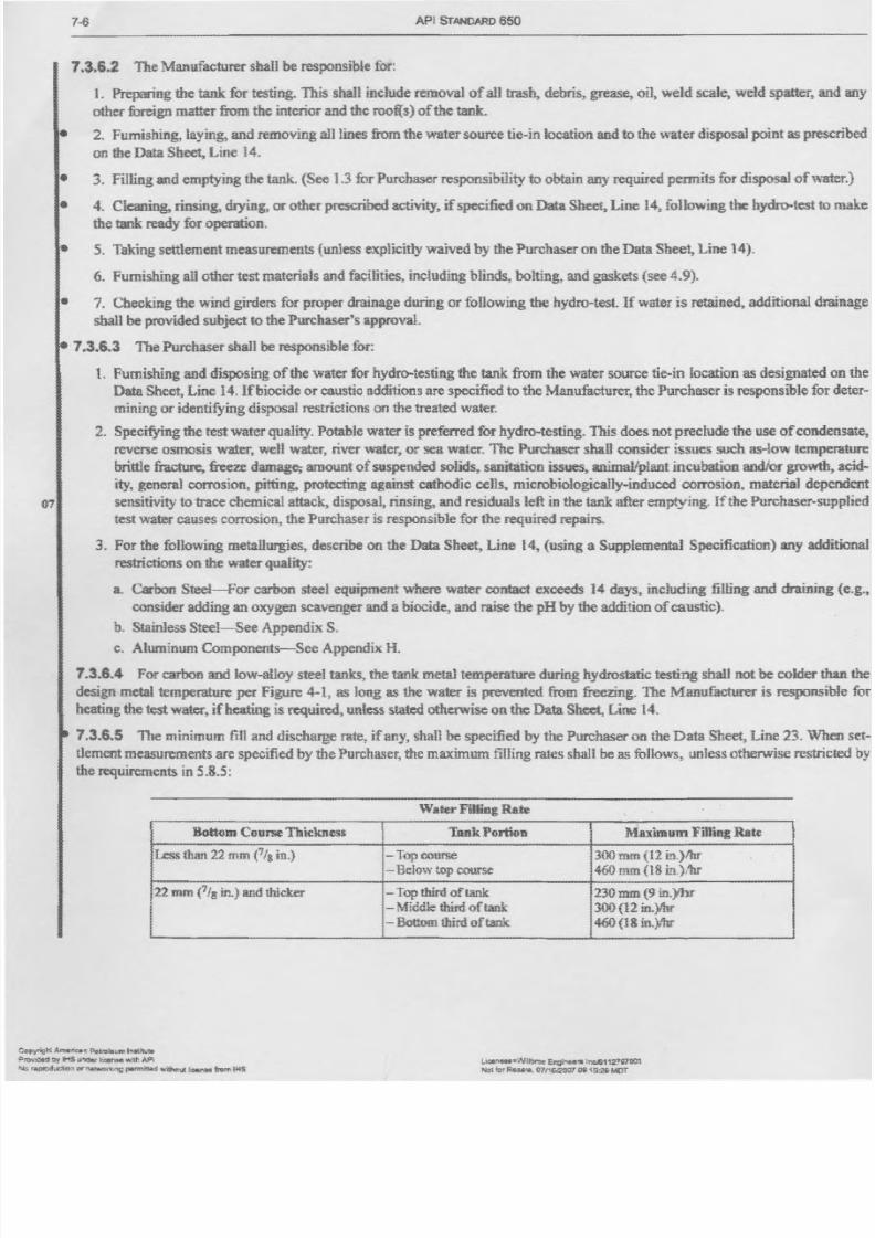
7-6 A PI S TA ND AR D 6 50
7.3.6.2 The Manufacturer shall be responsible for:
1. Preparing the tank for testing. This shall include rem oval of all trash, debris, grease, oil, w eld scale, w eld spatter, a
other foreign m atter from the interior and the roofls) of the tank.
• 2. Furnishing, laying, and rem oving all lines from the water source tie-in location and to th e wate r d is po sa l p oin t a s p re
on the Data Sheet, Line l4.
• 3. Filling and emptying the tank. (S ee 1 .3 fur P urchaser responsibility to obtain any required perm its for disposal of w
• 4. Cleaning, rinsing, d ry in g, o r o th er p re sc rib ed a ctiv ity , if s pe cifie d o n Data Sheet, L in e 1 4. fo llowin g the hydro-test tth e t ank r eady for ope ra ti on .
• 5. Taking s ettlemen t meas uremen ts (u nle ss explicitly waived by the Purchaser on the Data Sheet, Line 14).
6. Furn ish in g a ll o th er te st m ate ria ls a nd facilities, including blinds, bolting, and gaskets (see 4.9).
• 7. Checking th e wind girders fur p ro pe r d ra in ag e d urin g o r fo llowin g the h yd ro -te st. If w ate r is re ta in ed , a dd itio na l d
shall b e p ro vid ed s ub je ct to the Pu rchase r's app rova l.
• 7.3.6.3 The Purchaser shall be responsible for:
L Furnishing an d disposing of the w ater for hydro-testing the t ank from the w ater source tie-in location as designated
D ata. S he et, L in e 1 4. Ifb io cid e o r ca ustic a dd itio ns a re sp ec ified to the Manu fa ctu re r, th e P urc ha se r is responsible fo
mining o r ident if ying d ispo sa l r es tr ic ti on s o n th e tre ate d w ate r.2. S pecifying the test w ater quality. P otable w ater is preferred for hydro-testing. T his does not preclude the use of cond
reverse osm osis w ater, w ell w ater, river w ater, or sea w ater. The Purc ha se r sh aH c onsid er issu es su ch a s-low temp
b rittle fra ctu re , fre ez e d amage ; amount of suspended solids. sanitarion issues. an im ailp la nt in cu ba tio n an dio r g rowth
ity, g en era l c orro sio n, p ittin g, p ro te ctin g aga in st c ath od ic cells. m icr ob io logi ca ll y- induced cor ro sion , ma te ri al dep
07 sensitivity to trace chem ic al a tta ck , d is po sa l, rin sin g, a nd residuals left in the tank after emptying. Iftbe Purchaser-su
te st w ate r c au se s c orro sio n, th e P urc ha se r is re sp on sib le for th e re qu ired re pa irs.
3. For the fo llowin g meta llu rg ie s, de sc rib e o n th e Data Sheet, L in e 14, (u sin g a S up pleme nta l S pe cific atio n) a ny a d
r es tr ic ti on s on the wa te rqua li ty :
a Carbon Steel-For carbon steel equipm ent w here w ater contact exceeds 14 days, including filling and d ra in in
consider adding an oxygen scavenger and a biocide, and raise the pH by tile addition of caustic).
b . S ta in le ss Steel-See A ppendix S .
c. Aluminum Components-See Appendix H.
7.3.B.4 For carbon and low-alloy steel tanks, th e tank metal temp eratu re d urin g h yd ro sta tic te stin g sh all n ot be colder
design m etal tem perature per Figure 4-1 , as long as the water is prevented from freezing. T he M anufacturer is responsi
h ea ti ng the test water, if heating is required, unless stated otherw ise on the D ata S heet, L ine 1 4.
7.3.6.5 The m in imum fill a nd d isc ha rg e ra te , if a ny , sh all b e sp ec ifie d by the P urchaser on the Data Sheet, Line 23. \V
tlement measurements are specified by the P urchaser, the m axim um filling rates shall he as follow s, unless otherw ise restri
the requirements in 5.8.5:
-----------------"--"- ----~--------ater Fiff il lg .R ll te
Rott'Om COIlI"SeThickness Tank Portion Maximum F illin g Rat e.
Less than 22 mm fIg in.) - T op course 300 mm(12 in.)/hr
- B elow top course 460 mm (18 b.)/br
:2 2mID ( 1 1 8 in.) and thi cke r - Top third of tank 230 mm (9 in.)Ihr
l- M iddle third of tank 300 (1 2 iD.)Ihr
- Bottom third of tank 460 (18 in.) lbr
l '. i Arntuif*CI ?lIl~:' lJm l"IIIti11JtG
IH S U ' lQ s c 1 : 0e r t. ~ w:lt: , . ,PI licemt"~!MIIbro~ EnaitMIana :r.di112rQ1'OO1
8/4/2019 API Hydrotest
http://slidepdf.com/reader/full/api-hydrotest 7/9
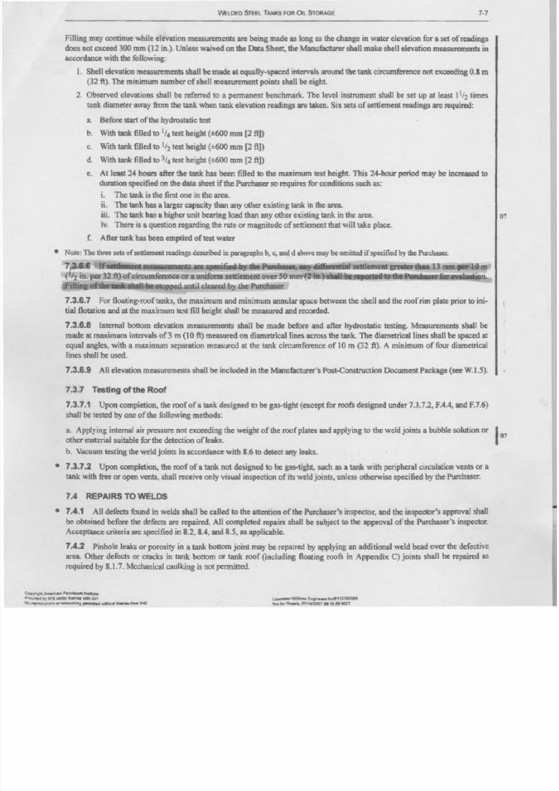
WEU1ED STEEL TANKS FOR OIL STORAGE
F illin g m ay c on tin ue w hile e le va tio n m ea su reme nts a re b ein g m ad e a s lo ng a s th e c ha ng e in w ate r e le va tio n f or a s et o f re ad in gs
does not exceed 300 m m (1 2 in.). Unle ss w aiv ed o n th e Data She et, th e Manu fa ctu re r s ha ll m a ke s he t! e le va tio n m e as ur em en ts in
accordance with the following:
1 . S he ll e le va tio n m ea su rem en ts s ha ll be made a te qu aUy -s pa ce d in te rv als a ro un d th e tank c ir cu tn fe re nc e n ot e xc ee din g 0 .8 m
(3 2 ft.). Th e minimum n um ber of she ll measurement point s s ha ll be eight
2. O bserv ed elev atio ns sh all b e referre d to a perm an en t ben ch mark. T he leve l instru men t sh all b e setu p at least 11/2 t imes
ta nk d iam ete r aw ay fro m the tan k w he n ta nk e lev atio n read in gs are tak en . S ix s ets o f s et tl ement r ea di ng s a re r eq ui re d:
a. Before start o f t he hydros ta ti c test
b. WIth tank fined to 1/4 te st h eig ht ( :1 :6 00mm [2 fi])
c. With tank filled to 1/2 t es t he igh t (±6oo mID {2 fi])
d . W i t.'l1 an k f ille d to 3/4 test h eig ht (± 6o o mm f2 ft])
e. A t least 24 hours after the tank h as b ee n filled to th e m ax im um te st h eig ht. T his 24 -h ou r p eriod m ay be i nc re as ed t o
d ur atio n s pe cif ie d o n th e d ata s he et if th e P urc ha se r so r eq uire s fo r c on ditio ns s uc h a s:
i, T he ta nk is th e firs t on e in th e a re a.
ii, T he ta nk h as a la rg er c ap ac ity ilia n a ny o th er e xis tin g ta nk in th e a re a.
iii. T he ta nk h as a h ig he r u nit b ea rin g lo ad th an a ny o th er e xis tin g ta nk in t he a re a. 07
iv. T here is a qu estion rega rdin g th e rate ()Jmagn itu de o f s ettlem en t th at will t ak e p la c e.
r . A fte r ta nk h as b ee n emp tie d o f te st w ate r
• Note: The three s ets o f s ettleme nt r ea din gs d es cr ib ed in p ar ag ra ph s b , c, a m} d a bo ve m ay be omitted if specified by th e Purchaser,
7".3.6.~ If~ent mc:asurements ar e the .Pun:1Iases, ally di trereJJt iai set tlement greater than m
(l/2 in. per 32 ft) of circumference or a uniform s ettleme nt o ve r 5 0 mm lJ tiHtiC n.Filling Qfihe stopped until cleared by the Purchaser.
7.3.6.7 F or flo atin g-r oo f ta nk s, th e m ax im um a nd m in im um a nn ula r s pa ce b etw ee n th e s he ll a nd th e r oo f r im p la te p rio r to ini-
t ia l f lo ta ti on and at th e m ax im um te st fill h eig ht s ha ll b e m ea su re d a nd r ec or de d.
7.3_6.8 In te rn al b ottom e le va tio n m ea su reme nts s ha ll be mad e b efo re a nd a fte r h yd ro sta tic t es ting . Measu rements s ha ll b e
m ade at m axim um intervals of 3 m (lQ it) mea su re d o n d iame tr ic al lin es a cro ss th e ta nk . T he d iame tr ic al lin es s ha ll b e s pa ce d a t
equ al an gles, w ith a m ax im um separatio n m easu red at th e tank circumference of 10 m (32 it). A m in im um o f f ou r d iame tric al
lin es s ha ll b e u se d.
7 .3 .6 .9 A li e le va tio n m ea su reme nts s ha ll b e in clu de d in th e Man ufa ctu re r's P os t-C on stru ctio n D oc um en t P ac ka ge ( se e W .l.S ).
7.3.7 Testing of the Roof
7.3.7.1 U pon com pletion, the roof of a tank designed to be gas-t igh t (except f or ro ofs d esig ne d u nd er 7.3.7.2, FA.4, and F .7 .6 )
shall be tested by o ne o f th e f ollow in g me th od s:
a. A pply ing in tern al air p ressure no ! ex ceed ing th e w eigh t of th e roo f p lates and ap ply ing to th e w eld jo ints a b ub ble solu tion o r
other ma te ri al s ui ta bl e f or t he d et ec ti on of leaks.
b . V ac uum te stin g th e w eld jo in ts in a cc or da nc e with 8 .6 to d ete ct a ny le ak s.
• 7.3.7.2 Up<>ncompletion, th e r oo f of a ta nk not d esig ne d to b e g as- tig ht, s uc h a s a ta nk w ith p er ip he ra l c ir cu la tio n v en ts o r Iitank with free o r open vents. shall receive o nly v is ua l in sp ec tio n o f its we ld j oi nt s, u nl es s otherwise s pe ci fi ed by t he Purchaser .
7.4 REPAIRS TO WELDS
• 1.4.1 A ll d efe cts fo un d in w eld s sh all b e caned to th e a tte ntio n o f th e P ur ch as er 's in sp ec to r, a nd th e in sp ec to r's a pp ro va l s ha ll
b e o bta in ed b ef or e the d ef ec ts a re re pa ire d. A ll c om ple te d r ep airs sh all b e s ub je ct to the a pp ro va l o f th e P ur ch as er 's in sp ec to r.
A c ce pta nc e c rite ria a re s pe cif ie d in 8 .2 , 8 .4 , a nd K .5 . a s a pp lic ab le .
7.4.2 Pinhole leaks or porosity in a tank bottom joint m ay be repaired by a pp ly in g a n a dd itio na l w eld b ea d o ve r th e d ef ec tiv e
area. O th er d efec ts or cracks in tank bottom or tank r oo f ( in clu din g f lo atin gr oo f- s in Appe nd ix C) jo in ts s ha ll he r ep air ed a s
re qu ir ed b y 8 .1 .7 . M ec ha ni ca l c al l1 ki ng i s n ot p ermi tte d,
Copyrig~ Ameri::.n P-tJot.\lRI ~e
?ro.,"!dt!i::l t:f Il-!S tJRr .: ter anaa W I I l \ AFI
No "'PrD<!UC"jonMnI&iwor1Unt1ptm1it1ad~utbnllafro.m f f o f S
~.=WIRbrtm Engins.. h:lE1 tj7Dl001Not~ ~tt.$Iilo. 07N6.JWO? 1/8:'f.5:;8fJ1iJT
7-7
8/4/2019 API Hydrotest
http://slidepdf.com/reader/full/api-hydrotest 8/9
7-8 AP I S T AND ARD 6 5 0- - - - - - - - - - - - - - - - - - - - - - - - - - - - - - - - - - - - - - - - - - - - - - - - - - - - - - - - - - - - - - - - - - - - - - - - - - - - - - - - - - - - - - - -7.4.3 A ll defects, cracks, or leaks in shell joints or the shell-to-bottom joint shall be repaired in accordance w ith 8.1 .7.
• 7.4.4 Repairs of defects discovered after the tank h as b een filled 'With water for testing shall be made 'With the water l
least 0.3 rn (1 ft) below an y po in t b ein g re paire d o r, ifr ep air s h av e to be made on or near the tank bottom, with the ta nk
W eldin g sh all n ot b e do ne o n an y tan k u nless all con nectin g lin es h av e been comp letely blin ded . R epairs sh all no t be attemp
a t ank th at is f ille d with oil or that bas contained oil until the t ank has been em ptied, cleaned, and gas freed. Repairs on a ta
ha s contained oi l shall no t be attemp te d b y th e Manufacturer unless the m anner of repair has been approved in w riting by th
ch aser and th e repairs are m ad e in th e p resence of th e Pu rch aser's in sp ecto r.
1.5 DIMENSIONAL TOLERANCES
• 7.5.1 General
The pU IPOse of the tolerances given in 7.5.2 through 7.5.7 is to produce a tank of acceptable appearance and to permit
functioning of floating roofs. Measurements shall be ta ke n p rio r to the hydrostatic water test Unless waiv ed o r m od ified
Pu rchaser on D ata Sheet, Line 15, or established sep arately b y agreem en t betw een th e Purchaser and th e M an ufactu rer. t
low ing to le ra nc es a pp ly :
7.5.2 Plumbness
a. l11C m aximum out-of-plum bness of the top of the shell relative to the bottom oftlle shell shall not exceed 1/200 of th
tank height. T he out-of-plum bness in one shell course shall not exceed the perm issible variations for flatness and wavinspecified in ASlM A 6M1A 6, ASTM A 20M /A 20, or A STM A 4ROMiA 480, whichever is applicable.
b . T he m ax im um o et-of-p lsm bn ess o f ro of co lumn s, gu id e po les, o r o ther v ertical in ternal comp onen ts sh all n ot ex ceed 1
t he t ot al height The 1 12 00 c rite ria sb aH also a pp ly to fix ed roof columns, F or tan ks w ith in tern al flp atin g ro ofs, ap ply th e
of thi~ s ec tio n o r Append ix H, wh ic he ve r is mo re s tr in ge nt.
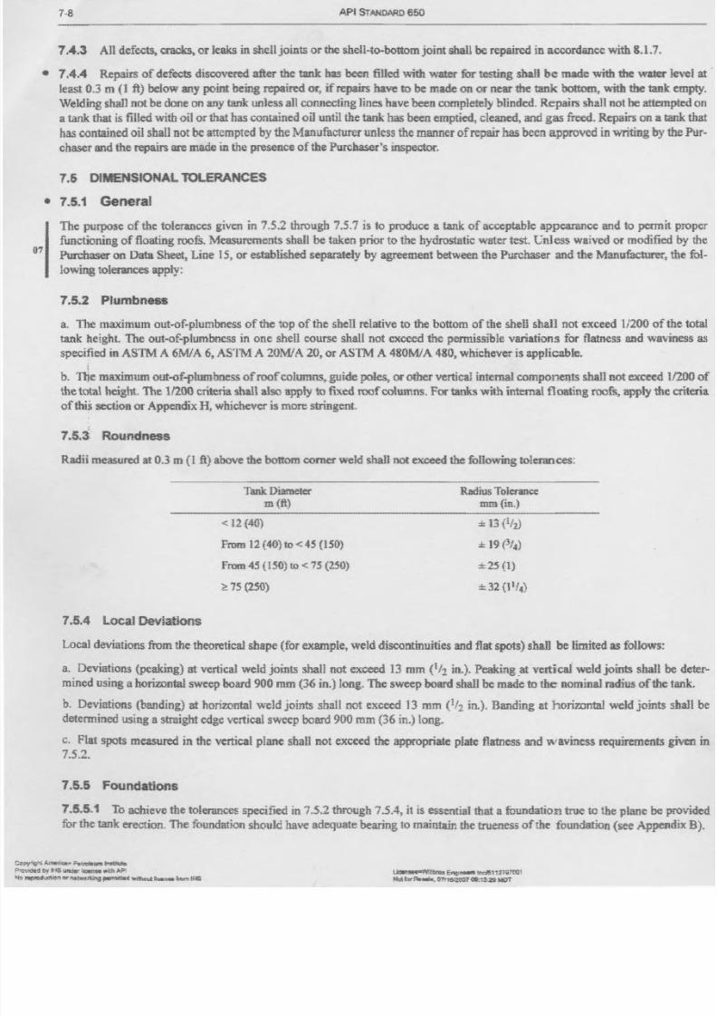
7 . 5 . a , Roundness
Radii measured at 0.3 m (1 ft) ab ov e th e b ottom co rn er w eld shall not e xc ee d th e f onow ing to le ra nc es :
Tank D iame te r
m (ft)Rad ius To le rance
mm (in.)
< 12 (40)
From 12 (40) to < 4S ( 15 0)
from 45 (ISO) to < 75 (250)
:< ! 75 (2S{)
:l: 13 ( !/ 21
± 19 (3 /4)
±25 (1)
± 32 (Il!4)
7.5.4 local Deviations
Local deviations from th e theoretical sh ape (fo r ex am ple, w eld discontinuities and flat sp ots) shall b e lim ited as fo llo ws:
a. Deviations (peaking) at vertical weld joints shall .80t exceed 13 mm (Ih in.), Peakingaivertical weld jo in ts s ha ll be
m ined using a horizontal sw eep board 900 rnm (36 in.) long. T he sw eep board shall be m ade to the nominal radiu s o f th e t
h. D eviations (banding) at horizontal w eld joints shall not exceed 13 mm (lh in.). B anding at hori7..ontal weld joints s
determ in ed usin g a straigh t ed ge vertical sw eep b oard 9 00 rnm (3 6 in .) lo ng.
c. Flat spots m easured in the vertical plane shall not exceed the ap prop riate p late flatn ess and waviness re qu irem en ts g
7.52.
7.5.5 Foundations
7.5.5.1 T o ach iev e the to leran ces sp ecified in 7_5.2through 7.5.4, it is essential th at a f uundatiom true to the plane be p
for the ta nk e rec tio n. T he fo un da tio n sh ou ld have adequa te bea ri ng to m aintain the trueness of the foundation (see A ppend
A , f ' I ' M t _ m . . , ;::..-tmt.una J!'I~~
de!i by IHS urxt~ ilCWt:M ""i lh API
orMfNeonJng ~ wiltt¢1.4 R ur.l$O \CIrt I tHSUtanSH"'WJ!bras Ef'lg:ftUIIllnrJi511V;;100i
Nd fOtRe ll ll is .01"I1MZOO708:1: s. a MDT
8/4/2019 API Hydrotest
http://slidepdf.com/reader/full/api-hydrotest 9/9