Embed Size (px)
Citation preview

A REVIEW OF ACCELERATOR CONCEPTS FOR TRE HYDROTEST FACILITY’
Alan J. Toepfer Science Applications International Corporation, Albuquerque, NM, USA
Absnact Tbe Mmrxcd Hydrotest Facility (AHF) is a facility
under consideration by the Department of Energy 0 for conducting explosivelydriven hychdynamic experiments. The major diagnostic tool at AM: will be a ndiogiap&y accelerator having radiation output capable of penenating very dense dynamic objects on multiple viewing axes with multiple pulses on each axis, each pulse having a Lime resolution capable of fiezing object motion (= 50-ns) and achieving a sparial resolution - 1 mm at the o b j e a Three acrzlerator technologies an: king Considered for AHF by the DOE national
and Sandh (SNL). Two of these are electron a a x m lhat will pmduce intense x-ray pulses from a converter target yielding a dose - 1.ooO - Zoo0 W @ 1 meter. LLNL has proposed a 16 - 20 MeV, 3 - 6 ICA linear induction aaxkmm (LIA) driven by FFT-swircbed mcxlularors driiting metglas bded cavities. SNL has proposed a 12-MeV, #kA Inductive Voltage Adder (IVA) ixelenur based on HERMES III p s e d power technology. The third option is a 25 - 5-V p a o n m l e n t c c capable of - 10” protondpulse ppased by LANL. This paper will review tbe ament status of ibe three accelmusr concepts for AKF.
laboratories at Los Alamos (LANL), Livemore (UNL),
1. INTRODUCTION X-radiography is a well-known diagnostic for
nondestructive test measurements, both of static ad dynamic systems. Pulsed x-radiography is commonly used for the study of a number of physical problems involving the hydrodynamics of materials. for example, the sfability of aaxlemed material interfaces and b e response of targels to ballistic penetration. Intense. single-pulse x-ray sources have been used for Lbe past 30 years to smdy hydrodynamic phenomena at the e x m e energy densities pcduced in the hydrodynamic stage of a nuclear &&on (before criticality). Tditionally this data. obtained in non-nuclear tests, has supplemented hat available from underground nuclear mu.
With the advent of the Comprehensive Test Ban Treaty (CTBT), assurance of the safety and reliability of the U.S. nuclear stockpile in the absence of under@ testing requires the development of high resolution pulsed radiography systems capable of obtaining multi-axis, multi-pulse data in a single dynamic test The ultima&
goal of this Ahnced Hydrotest Facility (AH??) is to poduce a high-resolution ndiographic movie of a dynamic test object. Achievement of this goal requires tbe deweloptnent of a numbet of new technologies including auxl- converters, beam steering/optics, and deteaon which make up the AHF system, as well ;is tbe compurarional tools needed to interpret aDd visualite the data This paper reviews a c c z l m technologies proposed for AHF which are currently Lmder developrnrnt by he DOE laboratories af U-NI, LANL, and SNL.
2. TECHNOLOGY APPROACHES TberearepresentlytwoconceptuaIapproacbestoAHF
radiography, the traditional x-ray sourcc poduced by be interaction of a beam of (12 - 20 MeV) electrons with a high 2 ‘mv& &get, a d a newer apprwch using a pulsed team of (25 - SOGeV) protons lo dirtctly indiafe tbe ltst object. which are tben imaged by an innowive magnetic lens system. Both appmches must be upable of penemhg tbe high density test object and achieving tbe required spatial and ternpod resolutions to resolve phenomena of interest The resulting radioppbic some requirements for each approach are given in Table 1.
Table I: AHF Radiorrraphic Source Reauiremenu
Equivalent flux -kRads @ lm
5 - 10
Pulse separation (uLs) I 0.2 -15 1 0.2 - 15 ,
Temporal coverage (p) [ 1.5 - 75 1 1.5 - 75
2.1 X-Radiography Approaches The U.S. hydrodynamic x-radiography program has
traditionaIly used e l m linacs such as the D M e V Phermex r f - l k ai LANL. and the 18-MeV FXR single- pulse, linear induction accelerat~t (LIA) at L W . For AHFIUMLhasproposeda16-20MeV,3- 6 kG high repetition rate, solid-state modular driven LIA, with injector and cavity designs closely related to an xh-mxl LIA being developed for the Dual,&is W o g n p h y
Work supported by Sandia National Laboratories under Subcontraci No. AV-0973
Hydrotest Facility (DAFUiT) now being built at LAM, [I1
An alternate x-ray socTT& basal on high c m t . iDductive voltage adder (IVA) technology develcrped for weapon effects simulation has k e n proposed by SNL. psed power-based x-ray scur.%s were first develcrped aod have been used extensively by the British Atomic We3pons Establishment (AWE) fcx hydrMest radiography. These w h i n e s have typically been < IO-MeV in energy, but the Sandia-developed N A ttrhnology has extmkd tbe capabilities of these auxlerakxs to 20 MeV in tbe HER\tE.S III axelerator. The N A AHF proposal is an extension of a pulsed power radiography cOocepc &vel@ as one of b e options for DARHT. [2]. For AHF, SNL has pposed a 12-MeV, 60-kA, 50-ns pulse length IVA
2.2 Proton Radiography Proton radiography may be capable of measUring both
mass density and the atomic number of materials in tbe radiognphedobject For AHF, LANL has pposed a 25 - 50 GeV proton synchromn fed by an 8WMeV linac injector similar to LANSCE. The required beam flux is 5 x 10" protondpulse. A unique magnetic lens system is usedtodiscrimina te between Coulornb multiple Scaaering and nuclear (strong interaction) d n g effm to e x m target informatiQn. _. 3. ACCELERATOR TECHNOLOGIES In the following paragraphs we discuss the LLNL,
S N L , and LANL - propcsd accelerators for AM: in mcxe &mil, covering the unique featum of each, b e technology sfatus, and the issues to be resolved
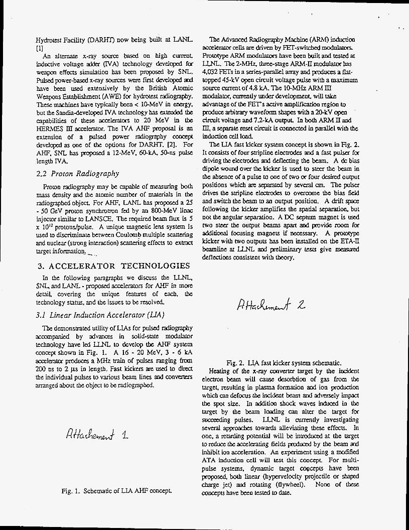
3.1 Linear Induction Accelerator (LL4) The demonstrated utility of LlAs for pulsed cdiography
axmpanied by advanas in solid-sute moddmr technology have led LLNL to develop tbe AHF system concept shown in Fig. 1. A 16 - 20 MeV, 3 - 6 kA amlentcr produes a MHz train of pulses ranging iiwn 200 ns to 2 p in length. Fast kickers an: used to direa the individual pulses to various beam lines and mverters amnged about the object [o be radiographed.
Fig. 1. Schematic of LIA AHF concept
IbeAdWCZdRadiographyMaCbilX(ARM)inductim ac~krator elk driven by FET-switcbed Proiocype ARMmcduIatonhave been builtand M a t LLNL. The 2-MH.z. &-sage ARM-II modulator bas 4,032 FEh in a series-pallel a m y and p-oduxs a flat- topped 45-kV "pen circuit voltage pulse with a maximum source current of 4.8 kA. The 1Q.MHz ARM III modulator, currently under developmen& will take advantage of tbe FETs auivc a m p l i f i i region to produce arbitmy waveform shapes with a 2 l R V open Ctcuit voltage and 7.2-kA output In both ARM II and III, asepararcreset cirmitis connected inparalEelwith the induction cell load
The LIA fast kicker system concept is sbown in Fig. 2. I r coosists of four stripline elccmdes and a fast pulsa for driving tbe electrodes and deflecdng the beam. A dc bias dipolewoundoverthekidctr is used to steer the beam in the absence of a pulse to we of two or four desired output positions which are separated by several an The pllser drives the smpline elechodes to ovcloo~~le b e bias field and switch the beam to an output position. A drift sp.ule following the kicker amplifies the spatial Separation. but not thc angular separation. A Dc septum magnet is & two s e e r the output beams apart and provide foom for dditional focusing magnets if necessary. A prolotype kicker with two outputs has been installed on the J3A-U beamline at UM. a d preliminary tests give deflectioas consistent with tbeory.
Fig. 2. LIA fast kicker system schematic. Heating of the x-ray oooverter target by the incident
electron beam wil l cause desorbtioa of gas from the target, resulting in plasma formation and ion podmion which caa defms b e incident beam 2nd advemly impaa tbe spot size. In xklitioa shock waves in&uced in the target by the beam loading can alter the target for sweeding pulses. LLNL is currently investigating several appnracbes towards alleviating these effects. In me, a retarding potential will be intrcdmxl at the target tordux theaccelerating fields prcdoced by tbe beam ad inhibit ion acceleration. An experiment using a mcdlied ATA induction cell will test this concept For multi- pulse systems. dynamic target copcepts have kea p r o p o ~ both linear (hypervelocity projectile or shaped charge jet) and rotating (flywheel). None of these coocepts have been tested to date.

DISCLAIMER
This report was prepared as an account of work sponsored by an agency of the United States Government. Neither the United States Government nor any agency thereof. nor any of their employees, makes any warranty, express or implied, or assumes any legal liability or responsibility for the accuracy, completeness, or use- fulness of any information, apparatus, product, or process disclosed, or represents that its use would not infringe privately owned rights. Reference herein to any spc- cific commercial product, process, or service by trade name, trademark, manufac- turer, or otherwise does not necessarily constitute or imply its endorsement, recorn- mendktion, or favoring by the United States Government or any agency thereof. The views and opinions of authors expressed herein do not neccssariiy state or reflect those of the United States Government or any agency thereof.

DISCLAIMER
Portions of this document may be illegible electronic image products. Images are produced from the best available original document.

Two of tbe major techD010gy issues raised regclrding tbe LIA approach to AHF, namely the reliability of the solid- state electronics in the high voltage environmwf & the feasibility of the kicker to maintain beam quality for suitable spot size have been xkkesed by LWL in experiments d testing. Pmof-of-principle tests bare been encouraging. The remaining major issue to be addrersed for the LIA axeleratcy mcept is thaf of maintaining beam spot size at the target and developing a multi-pulse converter concept Tbe fust of tbese will be addressed on DARHT. Tbe seoond is the subject d ongoing reseatch at LLNL, LANL, and SNL aspart of the overall AHFptogram.
z. E v .
3 . 2 Inducsive Voltage Adder (IVA)
I Slmulatron
Theory q The SM. AHF concept is based on multiple modules
incorporating b e IVA pulse forming network shown in Fig. 3. Tbe - 1-p, 3-MV output from a Marx gewrator is transformed through three successive pulse sharpening stages to a 15-MV, 60-ns pulse driving the cavities. Charging of eight metglas Ioaded cavicies connecled in series is synchronized with laser triggered gas swiulhes to give a 12-MV voltage on the coaxial maptically insulated transmission line (MTTJJ. Electrons which are field emiued fiam tbe surt?ce of &he center charged condunor are trapped by tbe self-magnetic field of the Current in the line. An - 50-ns FWHM. f3-U ele-ctron team is p r ~ d u Z - i the ~ a r h ~ d e .
Rg. 3. N A pulse forming netwok The engineering of TVA acceleratocs is well in band,
bowever the physics of the high cmrenf x-ray mverter ckde is comDIex. Electrons incident on &be tarnet ae

supercollider (SSO. A fast kicker modulator extracts tbe beam from the LEB into the main ring, a d a combination of ferrite kickers and elecmstatic sepnrm team spliuers transfers tbe team bunches h m the main ring into ultimately twelve separate beam lines at the test tacility. The total number of 50-GeV protons stored in tbe main ring is - 3 x IO’*. An &er embdment of this concqx which assumed injection directly from the 80- MeV Iinx into a 5O-GeV synchrotron was publisbed in Ref. (41.
R M M 3
Fig. 5 Proton Eiadiography Concept Tbe rf technology assumed in the LAM, PRAD
concept is 45 MHz at injection (800 MeV), and is xakd to 53.3 MHz.a~lh_e enhaDce to the delivery system. Based on experience at Fermilab, the proton buDcbes shouldbe less than 5 N wide at extraCtioa time, ad if properly synchro- the bunch pattern will be repeared once e x h 150 ns for as long as team is delivered to be delivery system. At 800 MeV, a minimum 95% emittance of 4.7 x-mm-mrad is required.
From the requirements in Table I>he kicker rncddamr must be capable of pulsing up to 120 times on bxmd overa 1.5 - 75-ps interval. The ferrite kickers would be hiode driven and operated witb capxiton to make them resonant Elecuostati-splitten would be used to divide the beam transversely among two beam lines per stage.
Tbe number of beam lines at tbe target is aareody envisioned to be 8 - 12. Each beamline would transpcxt up to 10 pulses to the target In order to anange that be beams all arrive at the target simultaneously, the lines must be equal in length. These long beam lines appear to be the dominant cost driver for the PRAD. Interaction of the protons with the target occurs via
three dominant procsses: Multiple coulomb (elastic) xauering (MCS) from protons in the target nuclei. The MCS cross section increases with atomic number (A). Beam attenuation & to (inelastic) nuclear interactions with protons and neutrons in tbe target nuclei. The nuclear cross section &meam with increasing A.
c/
-
Energy loss &x to collisions with target electrons. The cross sectiw for this mmaaion increases very slowly with iDcreasing A
PRAD pmp0x-s to take advaorage of be di&ring depenknoftheebsticandiDelasticcmsssectiousw A to measaxe spatial and time resdved mass density axl mahial composition of tk target. To accomplish Lhis. LWL has developed a two stage magnetic lens geometry (inset. Fig. 5 ) which diffmtiateS between coulomb axl nuclear scdftaed beam @des. [SI SiDcc MCS mrmed particles aredetkad in tbe proctss, it is necessary to refocus them at the image plane following aperum 1. Tbesepam’clesaremeasuredwithIbeinetasticfluxattbe frnt deteaor. The MCS scauntd prorons are then strippedfrorn the txansmiued beam by aptme 2, so that the seaad deiecm measures only the beam component a a m d by nuclear Scauering. A@ysis of these two aansnined team c o r n p e n t s should provide datrt on target mass disaibutioa aod k P W pf-ofcoocept experiments have ken
successfully cpcjed out by LANL af m M e V on LANSCE and at 7 - 10 GeV on AGS at Brootbaven Na~ioaaI Laboratory (BNL). Experiments at LANSCE (Fig. 6) have poked b t h static and dynamic targets. wbenzas only static target experiments have been c3nied out at AGS. A x w beam Liae is cumnQy tnxk construction at AGS for Z C i e V , high intensity tes&
Fig. 6 Dynamic won radiographs from LANSCE PRAD has tbe potential to signilicantly improve tbe
utility of hydrodynamic radiography. The main rechnical issues assoaaLed * wi thbede ra to randbeaml inesa re the demonsnation of the kicker modulator, reSOoant ferrite kicker. and electrostatic beam splitters requid to e x t r a and transport the beaxn bunches to the target. proof-of- concept experiments must also be canied out at 30 - 50 GeV to demonstrate tbere are no ”unlmown unknowns” in tbe beam-target intemxion that could give rise to inadequate resolution, loss of material discrimination capability, cx unacoeptable back-
The capability to discgn material i&ntity Deeds to be demonstrated Experiments to dare have shown excellent mass density resolution. but do not differentiate maLerials

in the radiographed objects. reahre of PR4D.
This capability is a key
4. OUTLOOK Achieving the AHF objective of a high-resolution
radiographic movie of a dynamic test object extends fbe state of pulsed radiographic art well beyond present capabilities. The thrce approaches to developing a multi- pulse. multi-axis source-each have their pluses a-d minuses. The LIA concept is an extension of existing systems to incotporate modem power electronics, and Ibe N A technology is an unproven, but potentially lower cost alternative. The major challenge facing tbese x-ray approaches is &e development of multi-pulse converters having the radiation output ard spot size necessary to Q the job. PRAD is a potentially revolutionary appmxh which holds great promise for the long term, assuming no "unknown unknowns" are d i s c o v d but may be too costly a system.
The DOE National Laboratories at Los Alamos, Livermore, and Sandia have ernbrked on a multi-year research and development effort to establish the capabifity of each approach and are making significant progress. The rak of progress is limited primarily by the availability of funds and facilities. DARHT, when it comes fully on line at the end of 2002, will help to address some of tbe multi-pulse issues in a rml test environment &Tan only be approximated today.
5. ACKNOWLEDGMENTS The author would like to thank W g e Caporas0 of
hwrcnm Livennore National Laboratory, John McCIelIand of Los hlamos National Laboratory, and John Mxnchen of Sandia National Labcam 'cs for lheu cooperation in preparing this review paper.
6. REFERENCES [l] G. J. Caporaso, 'zinear Induction Acceleratoc
1997 Particle Accelerator Conference, Vancouver. B.C., Canada, May 12-16, 1997, (1997).
[2] D. L. Smith, el. af., "Proposed Inductive Voltage AdQr Based hleeratoc Concepts for the second Axis of DARHT," €'roedm gs of 11th lEEE International Pulsed Power Conferem, Baltimore, MD, Vol. 11, 1647 (1997).
[3] J. Maenchen, "Inductive Voltage Addcr Driven Rash Radiography," Bull. Am. Phys. Soc. (1998).
[4] F. Neri, H.A. Tbeissen, and P.L. Walstrom. "Synchrotrons and Beamlines for Proton Radiography," Pmxxdings of 1997 Panicle Accelerator Conference, Vancouver. B.C., Canada, May 12-16, 1997, (1997).
[s] C.T. Moueshead ard JD. Zumbro, 'Magnetic Optics for Proton Radiography," Proceedings of 1997 Particle Accelerator Conference, Vancouver. B.C., Canada, May 12-16, 1997, (1997).
Approach for Advanced Radiography," Froaxdm * gs of
Smdia is a multiprogram laboratory operated by Sanrlia Corporation, a hkheed Martin Company, for the U W States Department of Energy under contract DE-AC04-94AL85000.
1

c
LIA AHF system concept t
50 ns,
klckors
I 4 - 8 lines of ?-T? s igh t
16 - 20 MeV, 3 - 6 kA injector accelerator
L I 500 2W,&2PSii ns I 1 2.5 11s ,J I I ; I I
\ t \ # 1
I \
I varlable Interpulse I I
spac lngdown to 500 ns I
‘Or ‘lo pulses Metglas cel;
lnductlon adder
FET-sw I t c hed modulator
\ \ \ t \ \ \ .
hard tube modulator
n s
pJ /Losl(@ NATIONAL LABORATORY

Powering all 4 electrodes allows 4 or more output lines from the kibker
Y drive cab le
U 4- drive plate termination r
drive
*
bias dipole wi
1 I t n septum magnetJ
tched beam pos i t ion
Los Alamos -1 JNITH)UIIUIBORITORII 0 AtlF98.034/dJC14-2 1-98lAPS. I2

SO GeV Ring
c
3
Conceptual Proton Radiographic 1 F aci I i ty 4
4 W k G l - k - d - Science Brrsecl Srockp ile Slcwirt-clsh ip
Object
L . _. - ~ ~ _ . . __ . .__ J
Optical analogy of magnetic lens s y s t e 2 z w n s e c <5 nsec wide
U\<U 28-pulses spread out over 75 psec
Pulse structure in each beamline
: 1

High Explosive Radiographs and Reconstructions wiith Protons
0.99 psec
1.90 p c c
2.50 psec
,* 1. " . ,
Y
c 3.25 pscc