Embed Size (px)
Citation preview

55:041 Electronic Circuits. The University of Iowa. Fall 2013.
Homework Assignment 04
Question 1 (Short Takes). 2 points each unless otherwise noted. 1. The op-amp in the circuit is ideal, and 𝑅1 = 10K, 𝑅2 = 100K, and 𝑅3 = 10K. The input
resistance that the source sees is
(a) 𝑅1 = 10K (b) 𝑅1 + 𝑅3 = 20K (virtual short between + and −) (c) ∞ (Ideal op-amp has 𝑅𝑖 = ∞) (d) 𝑅1||𝑅2||𝑅3 = 4.72K (KCL at – terminal)
Answer: 𝑅1 = 10K, so (a) is the answer.
2. The op-amp in the circuit is ideal, except for non-zero input bias currents. Further, 𝑅1 = 10K and 𝑅2 = 30K. What should 𝑅3′𝑠 value be?
(a) 10K (b) 𝑅1 + 𝑅2 = 30K (c) 0 Ω (d) 𝑅1||𝑅2 = 7.5K
Answer: 𝑅3 compensates for input bias currents and a rule of thumb is to choose 𝑅3 =𝑅1||𝑅2, so the answer is (d).
3. A resistor has a nominal value of 10K, but its actual value is 9.98K. What is the percentage error?
(a) 0.02K (b) −0.02K (c) −0.2% (d) (e) 0.2% Answer: Percentage error is ((9.98− 10) 10⁄ ) × 100 = −0.2%, so the answer is (d)
4. The op-amp in the circuit is ideal, except that the open-loop gain is finite, namely 𝐴𝑑 = 100,000. Further, 𝑅2 = 100K and 𝑅1 = 10K. If, for some input signals, the output is 𝑣𝑂 = −5 V, then
(a) 𝑣− = 𝑣+ = 0V (virtual ground concept) (b) 𝑣− = 50 𝜇V (c) 𝑣− = +50 𝜇V (d) Need additional information: 𝑅3, 𝑣𝑠
Answer: The input bias current is zero and input offset voltage is zero, so 𝑣+ = 0 V. However, the gain is finite, so 𝑣− ≠ 𝑣+. For a −5 V output, 𝑣− must be 𝑣− = 𝑣𝑂 𝐴𝑑⁄ =5 100,000 = 50 𝜇V⁄ , so the answer is (b) or (c).
1

55:041 Electronic Circuits. The University of Iowa. Fall 2013.
5. In the circuit below, the op-amp is ideal, except for an input bias current 𝐼𝑏 = 1 nA. Further, 𝑅𝐹 = 10K,𝑅1 = 100 Ω and 𝐶 = 1 𝜇𝐹. The switch is opened at 𝑡 = 0. What is the output voltage after 5 seconds? (4 points)
(a) ≈ +500 mV (b) ≈ −500 mV (c) ≈ ±500 mV (d) Need additional information
Answer: For 𝑡 ≥ 0, the voltage across the capacitor is 𝑣𝐶 = (±𝐼𝑏Δ𝑡) 𝐶⁄ which is �(±1 × 10⁻⁹) (5)� (1 × 10⁻⁶)⁄ = ±5 mV for 𝑡 = 5 s. The gain of the amplifier is 1 + 𝑅𝐹 𝑅1 = 101⁄ , so that the output voltage is ± 501 mV. Thus (c) is the answer.
6. What is the output voltage 𝑉𝑂𝑈𝑇 at the end of the 2.82 ms pulse? (4 points)
(a) ≈ 0 V (b) ≈ 0.75 V (c) ≈ 5.55 V (d) ≈ 14.25 V
Answer: On the rising edge the capacitor is uncharged and 15V appears across 𝑅1. The voltage across the capacitor is 𝑉𝐶 = 15�1 − 𝑒−𝑡 𝜏⁄ � where 𝜏 = 𝑅𝐶 = 940 𝜇s is the time constant. The voltage across 𝑅1 is 15𝑒−𝑡 𝜏⁄ . At 𝑡 = 2.82 ms, this is 5𝑒−2.82 ms 940 𝜇s⁄ =15𝑒−3 = 0.747 V, so the answer is (b).
7. What is the 3-dB bandwidth of the circuit below?
(a) 63.6 Hz (b) 31.8 Hz (c) 5.07 Hz (d) 10.1 Hz
Answer: The capacitor sees an equivalent resistance 𝑅𝑆||𝑅𝐿 = 5K. The time-constant is 𝜏 = 𝑅𝐶 = 5 ms, so that the bandwidth is 1 (2𝜋𝜏) = 31.82 Hz⁄ , and (b) is the answer.
8. What frequency is 2.2 decades higher than 500 Hz?
(a) 1.01 kHz (b) 644 Hz (c) 522 Hz (d) 79.24 kHz
Answer: 2.2 = log(𝑓𝑥 500⁄ ), so that 𝑓𝑥 = 79.24 Hz, so (d) is the answer.
2

55:041 Electronic Circuits. The University of Iowa. Fall 2013.
9. What is frequency is 3 decades down from 220 Hz?
(a) 22 mHz (b) 220 mHz (c) 6.4 mHz (d) 190 Hz Answer: 3 = log(220 𝑓𝑥⁄ ), so that 𝑓𝑥 = 220 mHz, so (b) is the answer.
10. A signal with amplitude 𝑣 = 4 V at 4 kHz decreases as frequency increases at −2 dB/octave. What is the amplitude in V at 13 kHz? (3 points) Answer: There are log2(13 2⁄ ) = 1.7octaves between 4 kHz and 13 kHz. Thus, the amplitude decreases by 1.7 × 2 = 3.4 dB. The new amplitude is 20 log 4 − 3.4 = 8.6 dB. This is equivalent to 2.7 V.
11. A 10 mW signal is equivalent to a power of
(a) −20 dB (b) −40 dB (c) 20 dB (d) 0dB Answer: 𝑃𝑑𝐵 = 10 log(10 × 10−3) = −20 dB, so the answer is (a)
12. A 9-V dc power supply generates 10 W in a resistor. What peak-to-peak amplitude should an ac source have to generate the same power in the resistor?
(a) 12.73 V (b) 25.5 V (c) 18 V (d) 12.73 V Answer: The ac source’s effective (or rms) value should also be 9 V. This measn the peak value should be 9√2 V, so the peak-to-peak value should be 18√2 = 25.5 V, so the answer is (b).
13. Consider the single-supply op-amp amplifier shown. What is the purpose of 𝑅3?
Answer: This compensates for the op-amp’s input bias current. The value should be R1||R2.
3

55:041 Electronic Circuits. The University of Iowa. Fall 2013.
14. The single-supply op-amp amplifier shown has a serious flaw. What is it?
Answer: There is no dc path to bias the non-inverting input.
15. An engineer measures the (step response) rise time of an amplifier as 𝑡𝑟 = 0.7 𝜇s. Estimate the 3 dB bandwidth of the amplifier.
Answer:
𝐵𝑊 ≅0.35𝑡𝑟
=0.35
0.7 × 10−6
= 500 kHz
16. A 𝐼𝑅𝐸𝐹 = 1 mA current source has an output resistance 𝑅𝑜 = 100 kΩ and drives a 1 kΩ load. What current flows through the load? (2 point) Answer: 𝐼𝑙𝑜𝑎𝑑 = 𝐼𝑅𝐸𝐹[100 (100 + 1)⁄ ] = 0.99 mA
17. A single-pole op-amp has an open-loop low-frequency gain of 𝐴 = 105 and an open loop, 3-dB frequency of 4 Hz. If an inverting amplifier with closed-loop low-frequency gain of �𝐴𝑓� = 50 uses this op-amp, determine the closed-loop bandwidth. Answer: The gain-bandwidth product is 4 × 10⁵ Hz. The bandwidth of the closed-loop amplifier is then is 4 × 10⁵/50 = 8 kHz.
4

55:041 Electronic Circuits. The University of Iowa. Fall 2013.
18. A single-pole op-amp has an open-loop gain of 100 dB and a unity-gain bandwidth frequency of 2 MHz. What is the open-loop bandwidth of the op-amp?
Answer: A gain of 100 dB corresponds to 105 and the gain-bandwidth product is 2 MHz. Thus, the open-loop bandwidth is (2 MHz) 105⁄ = 20 Hz
19. A single-pole op-amp has an open-loop gain of 100 dB and a unity-gain bandwidth frequency 5 MHz. What is the open-loop bandwidth of the amplifier? The amplifier is used as a voltage follower. What is the bandwidth of the follower? (3 points)
Answer: A gain of 100 dB corresponds to 105 and the gain-bandwidth product is 5 MHz. Thus, the open-loop bandwidth is (5 MHz) 105⁄ = 50 Hz. A unity follower will have a bandwidth of 5 MHz.
20. Consider a frequency 𝑓1 = 2.4 Hz. How many octaves higher is the frequency 𝑓2 =10 Hz? (3 points)
Answer: Each octave means a doubling in frequency. Thus, we have to find 𝑛 in 𝑓2 = 2𝑛𝑓1. Substituting values gives 𝑛 = log(10 2.4⁄ ) log(2) = 2.06⁄ octaves.
21. Consider a frequency 𝑓1 = 2.4 Hz. How many decades higher is the frequency 𝑓2 =10 Hz? (3 points)
Answer: Each decade means a frequency 10 × higher. Thus, we have to find 𝑛 in 𝑓2 = 10𝑛𝑓1. Substituting values gives 𝑛 = log(10 2.4⁄ ) = 0.62 decades.
22. Consider a first-order RC low-pass filter with 3-dB frequency 𝑓 = 25 Hz. What is the phase shift in degrees at 75 Hz? (3 points) Answer: The phase shift at 25 Hz is 45° and increases at 45° / decade. 75 Hz is log(75 25) = 0.48⁄ decades higher than 25 Hz. Thus, the phase shift is 45 + 0.48 ×45 = 67°. A more accurate calculation gives the phase shift as tan−1(75 25⁄ ) = 72° .
5
55:041 Electronic Circuits. The University of Iowa. Fall 2013.
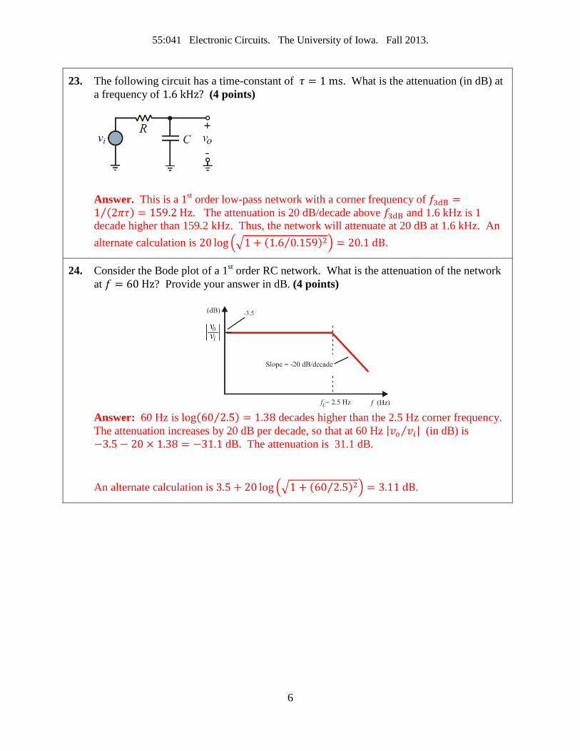
23. The following circuit has a time-constant of 𝜏 = 1 ms. What is the attenuation (in dB) at a frequency of 1.6 kHz? (4 points)
Answer. This is a 1st order low-pass network with a corner frequency of 𝑓3dB =1 (2𝜋𝜏) = 159.2 Hz⁄ . The attenuation is 20 dB/decade above 𝑓3dB and 1.6 kHz is 1 decade higher than 159.2 kHz. Thus, the network will attenuate at 20 dB at 1.6 kHz. An alternate calculation is 20 log ��1 + (1.6 0.159⁄ )2� = 20.1 dB.
24. Consider the Bode plot of a 1st order RC network. What is the attenuation of the network at 𝑓 = 60 Hz? Provide your answer in dB. (4 points)
Answer: 60 Hz is log(60 2.5⁄ ) = 1.38 decades higher than the 2.5 Hz corner frequency. The attenuation increases by 20 dB per decade, so that at 60 Hz |𝑣𝑜 𝑣𝑖⁄ | (in dB) is −3.5 − 20 × 1.38 = −31.1 dB. The attenuation is 31.1 dB. An alternate calculation is 3.5 + 20 log ��1 + (60 2.5⁄ )2� = 3.11 dB.
6

55:041 Electronic Circuits. The University of Iowa. Fall 2013.
Question 2 A 0.22 F capacitor is charged to 5 V. Now assume a 50 ms, 1-A (constant) current pulse drawn from the capacitor. What is the resulting voltage across the capacitor? (4 points) Solution A 0.22 F capacitor is charged to 5 V. contains a charge of 𝑄 = 𝐶𝑉 = 0.22 × 5 = 1.1 C. A 50 ms, 1A discharge is equivalent to a charge of Δ𝑄 = 𝐼Δ𝑡 = 50 mC , and the charge remaining after the pulse is 1.05 C. Thus, the voltage across the capacitor is
𝑉 =𝑄𝐶
=1.050.22
= 4.77 V
7

55:041 Electronic Circuits. The University of Iowa. Fall 2013.
Question 3 For the circuit below, derive an expression for the output voltage as a function of 𝑉𝑂𝑆, 𝐼𝑁 ,𝐶,𝑅, and time. (8 points)
Solution
Below is a model of an inverting integrator that incorporates 𝐼𝑁 and 𝑉𝑂𝑆.
The voltage at the inverting input is 𝑉𝑂𝑆 so that a KCL equation at this node is
𝑉𝑂𝑆𝑅
+ 𝐼𝑁 + 𝐶𝑑𝑣𝐶𝑑𝑡
= 0
where 𝑣𝐶 = 𝑉𝑂𝑆 − 𝑣𝑂(𝑡) is the voltage across the capacitor. Since 𝑉𝑂𝑆 is a constant
𝑉𝑂𝑆𝑅
+ 𝐼𝑁 + 𝐶𝑑𝑣𝑂𝑑𝑡
= 0
𝑣𝑂 = −1𝐶� �
𝑉𝑂𝑆𝑅
+ 𝐼𝑁� 𝑑𝑡 = −1𝐶�𝑉𝑂𝑆𝑅
+ 𝐼𝑁� 𝑡𝑡
0
8

55:041 Electronic Circuits. The University of Iowa. Fall 2013.
Question 4 An op-amp has a voltage gain of 100 dB at dc and a unity-gain frequency of 5 MHz. What is 𝑓𝐵, the low frequency 3-dB cutoff frequency? Write an expression for the transfer function 𝐴(𝑓) for the open loop gain of the op amp. Assume that the op-amp has a single-pole frequency response. (6 points)
Solution
100 dB of voltage gain is equivalent to a voltage gain of 105 and the GBW is 5 MHz. Thus, the low frequency 3-dB point is 5 × 10⁶ 105 = 50 Hz.⁄ The transfer function is
𝐴(𝑓) =105
1 + 𝑓50
=5 × 10⁶
50 + 𝑓
9

55:041 Electronic Circuits. The University of Iowa. Fall 2013.
Question 5 Find the output resistance impedance 𝑍𝑜𝑢𝑡 of the circuit shown. That is the impedance looking into terminals 𝑎 and 𝑏. (8 points)
Solution Here are the steps. Turn off the independent source. Add a test source 𝑉𝑥 and determine the current 𝐼𝑥 that flows. Then 𝑍𝑜𝑢𝑡 = 𝑉𝑥 𝐼𝑥⁄ . The circuit after turning off the independent source and adding 𝑉𝑥 is shown below.
KCL at terminal 𝑎, using the convention that currents flow into the node gives
𝐼𝑥 + 0.2𝑉𝑜 + 𝐼1 = 0
Note that
𝐼1 = −𝑉𝑥
(8 + 𝑗4 ) + (4 − 𝑗2) = −𝑉𝑥
12 + 𝑗2
Further, the control voltage for the controlled current source is 𝑉𝑜 = −𝐼1(8 + 𝑗4). Substituting the expression for 𝐼1 and 𝑉𝑜 into the KCL equation gives
𝐼𝑥 − (0.2) �𝑉𝑥
12 + 𝑗2 � (8 + 𝑗4) −
𝑉𝑥12 + 𝑗2
= 0
Solving for 𝑍 = 𝑉𝑥 𝐼𝑥⁄ yields 𝑍𝑜𝑢𝑡 = 4.4324 − 𝑗0.5946 = 4.472∠ − 7.64° Ω
10

55:041 Electronic Circuits. The University of Iowa. Fall 2013.
Question 6 Use superposition to determine 𝑖 in the network below if 𝑣𝑠 = 7 V and 𝑖𝑠 = 21 mA. (8 points)
Solution The strategy is to turn off 𝑣𝑠 and find the resulting current 𝑖′ through the 3-K resistor. Then, turn off 𝑖𝑠 and find the resulting current 𝑖′′ through the 3-K resistor. The answer, using superposition is 𝑖 = 𝑖′ + 𝑖′′.
Turn 𝑖𝑠 off, which means removing it from the circuit. Then, 𝑣𝑠 supplies a current 𝑣𝑠 (2K + 3K||3K) =⁄ 𝑣𝑠 (3.5K)⁄ . Using current division, 𝑖′ is half of this current, namely 𝑖′ = 𝑣𝑠 7K⁄ = 1 mA.
Next, turn off 𝑣𝑠, which means shorting it. The resulting circuit is shown below.
The current 𝑖𝑥 (using current division) is
𝑖𝑥 =2
(1 + 2||3) + 2𝑖𝑠 =
1021
𝑖𝑠
The current 𝑖′′ (again using current division) is
𝑖′′ = �1021
𝑖𝑠�25
=4
21𝑖𝑠 =
421
(21) = 4 mA
Then, using superposition 𝑖 = 𝑖′ + 𝑖′′ = 1 + 4 = 5 mA
11

55:041 Electronic Circuits. The University of Iowa. Fall 2013.
Question 7 Determine an expression for the closed-loop gain 𝑣𝑂 𝑣𝑆⁄ for the circuit shown. Calculate the numerical value of the gain if all the resistors are have value 10K, except for 𝑅3 which has value 20K. Assume the op-amp is ideal. (12 points)
Solution KCL at the inverting input gives
𝑣− − 𝑣𝑆𝑅1
+𝑣− − 𝑣𝑂𝑅2
= 0 ⇒ 𝑣− =𝑅2
𝑅1 + 𝑅2𝑣𝑆 +
𝑅1𝑅1 + 𝑅2
𝑣𝑂
𝑣+ follows from voltage division
𝑣+ =𝑅3
𝑅3 + 𝑅4𝑣𝑂
The op-amp is ideal so 𝑣+ = 𝑣− so that
𝑅3𝑅3 + 𝑅4
𝑣𝑂 =𝑅2
𝑅1 + 𝑅2𝑣𝑆 +
𝑅1𝑅1 + 𝑅2
𝑣𝑂
After some algebraic manipulation
𝑣𝑂𝑣𝑆
=𝑅2(𝑅3 + 𝑅4)
𝑅3(𝑅1 + 𝑅2) − 𝑅1(𝑅3 + 𝑅4)
Setting 𝑅1 = 𝑅2 = 𝑅4 = 10K and 𝑅3 = 20K gives
𝑣𝑂𝑣𝑆
=(10)(20 + 10)
(20)(10 + 10) − (10)(20 + 10) =300
400 − 300= 3
12

55:041 Electronic Circuits. The University of Iowa. Fall 2013.
Question 8 The op-amp in the circuit is ideal, except for non-zero input bias currents with value 𝐼𝑏 = 100 nA. Further, 𝑅1 = 50K and 𝑅2 = 300K. The 10-mV source has an internal resistance of 𝑅𝑆 = 50K. Determine the worst-case error in 𝑣𝑂 resulting from 𝐼𝐵. Express the error as a percentage. (6 points)
Solution The input bias current generates a voltage ±𝐼𝑏𝑅𝑠 = ±(100 × 10−9)(50 × 103) = ±5 mV. The ± results from the fact that 𝐼𝑏 could be flowing in or out of the op-amp. This voltage adds/subtracts from 𝑣𝑆 and the resulting voltage is amplified by 1 + 𝑅2 𝑅1⁄ = 7. Thus, the output voltage is
𝑣𝑂 = (7)(10 ± 5 mV) = 70 ± 35 mV
Thus, the error is ± 35 mV
Without 𝐼𝑏 the op-amp’s output would be (7)(10 mV) = 70 mV. The percentage error is therefore
70 − (70 ± 35)70
× 100 = ±50%
13

55:041 Electronic Circuits. The University of Iowa. Fall 2013.
Question 9 (Own) An engineer uses the circuit shown to estimate both the input offset voltage 𝑉𝑂𝑆 and input bias current 𝐼𝐵 for the op-amp as follows. A 𝑡 = 0 she opens the switch and measures the output voltage 𝑉𝑜 at different times. The table shows her measurements for 𝑅1 = 10 Ω,𝑅𝐹 = 1K, and 𝐶 = 1 𝜇F.
(a) Redraw the circuit showing 𝐼𝐵 and 𝑉𝑂𝑆 (2 points)
(b) The op-amp, 𝑅1, and 𝑅𝐹 form an amplifier. What is
the gain of the amplifier? (2 points)
(c) Use her data and estimate 𝑉𝑂𝑆 (3 points)
(d) Use her data and estimate 𝐼𝐵. (6 points)
You may assume 𝐼𝐵 is constant
𝑡 (seconds) 𝑉𝑂 (V) 0 5.05 20 5.27 40 6.40 60 7.08
Solution
Part (a)
Part (b) 𝐴𝑣 = (1 + 1,000 10⁄ ) = 101
Part (c) When the switch is closed (𝑡 = 0) the op-amp amplifies the offset voltage which results in an output voltage 𝐴𝑣𝑉𝑂𝑆 = 5.05 𝑉 (see table), so that 𝑉𝑂𝑆 = 5.05 101⁄ = 5 mV.
Part (d) After the switch opens, 𝐼𝐵 charges the capacitor the output voltage rises. From the differential equation for a capacitor 𝑖 = 𝐶(𝑑𝑉 𝑑𝑡⁄ ) it follows that
𝐼𝐵 = 𝐶Δ𝑉𝐶Δ𝑡
=𝐶𝐴𝑉
Δ𝑉𝑂Δ𝑡
From the table, Δ𝑉𝑂 Δ𝑡⁄ is about 2 60⁄ V/s after the switch opens. Substituting values gives
𝐼𝐵 =𝐶
101 Δ𝑉𝑂Δ𝑡
=1 × 10⁻⁶
1012
60= 330 pA
14

55:041 Electronic Circuits. The University of Iowa. Fall 2013.
Question 10 The open-loop low-frequency gain of an op-amp is 100 dB. At a frequency of 𝑓 = 104 Hz, the magnitude of the open-loop gain is 38 dB. The op-amp has a dominant-pole open-loop response. Determine the frequency of the dominant pole and the unity-gain bandwidth. (5 points)
Solution
Open-loop dominant pole response implies constant GBP, which is
𝐺𝐵𝑃 = 1038 20⁄ × 104 = 794.4 × 10³
The dominant-pole frequency is
𝑓 =𝐺𝑃𝐵
10100 20⁄ = 7.94 Hz
The unity-gain bandwidth is the same as GBP.
15

55:041 Electronic Circuits. The University of Iowa. Fall 2013.
Question 11 The figure below is a plot of the open-loop gain function for the LF357 voltage amplifier. An engineer will use the amplifier in a negative feedback configuration to set the mid-frequency voltage gain at 100. Use the plot and estimate the bandwidth of the feedback amplifier. (5 points)
Solution. A gain of 100 is equivalent to a gain of 20 log10(100) = 40 dB. A horizontal line at 40 dB intercepts the LF357 gain curve at 100 kHz (see above). Thus, the bandwidth ~ 100 kHz.
16

55:041 Electronic Circuits. The University of Iowa. Fall 2013.
Question 12 Find 𝑣𝑁 , 𝑣𝑃 and 𝑣𝑂 in the circuit below if 𝑣𝑠 = 9 V. Assume an ideal op-amp. (6 points)
Solution
𝑣𝑃 = 𝑣𝑁 = 𝑣𝑂10
10 + 40=
15𝑣𝑂
KCL at 𝑣𝑁:
15 𝑣𝑂 − 9
50K+
15 𝑣𝑂 − 𝑣𝑂
20K= 0
Solving yields 𝑣𝑂 = −5 V, and 𝑣𝑃 = 𝑣𝑁 = −1 V
17

55:041 Electronic Circuits. The University of Iowa. Fall 2013.
Question 13 In the circuit below, find 𝐼2 and then 𝑉𝑜 using loop analysis. That is, write KVL equations for the two loops. (10 points)
Solution
KVL for loop 1:
−2𝑉𝑥 + (𝐼1 + 𝐼2)(2K) + 𝐼1(4K) = 0
KVL for loop 2:
−2𝑉𝑥 + (𝐼1 + 𝐼2)(2K) − 3 + 𝐼2(6K) = 0
Constraint:
𝑉𝑥 = 𝐼1(4K)
Combine these equations and rearrange:
−𝐼1(2K) + 𝐼2(2K) = 0 −𝐼1(6K) + 𝐼2(8K) = 3
Solve using any convenient method to find 𝐼2 = 1.5 mA. Consequently,𝑉𝑜 = (1.5 mA)(6K) =9 V
18