Embed Size (px)
Citation preview
1
Homework Assignment 3
The homework assignment should be solved individually. However, it is allowedto ask questions to fellow students. All solutions should be clearly written andwell motivated. Regarding the language, you may use Swedish or English.
The assignment is due on Wednesday, February 11, 2009. Please email yoursolutions to [email protected].
1 Reconstruction
This section contains some exercises on reconstruction taken from Ma et al.(2006). However, they are repeated below for convenience.
1. Essential Matrix for planar motionSuppose we know that the camera moves on a plane, say the xy plane(Note that moves here implies that we only allow rotations in the xy-plane). Show that:
(a) The essential matrix E = TR is of the special form
E =
0 0 a0 0 bc d 0
, a, b, c, d ∈ R. (1)
(b) Without using the SVD-based decomposition introduced in this chap-ter (5), find a solution to (R, T ) in terms of a, b, c, d.
2. Homography with respect to the second camera frameIn the chapter, we have learned that for a transformation X2 = RX1 + Ton a plane NTX1 = 1 (expressed in the first camera frame), we have ahomography H = R + TNT such that x2 ∼ Hx1 relates the two imagesof the plane.
(a) Now switch roles of the first and the second camera frames and showthat the new homography matrix becomes
H =(RT +
−RTT1 +NTRTT
NTRT). (2)
(b) What is the relationship between H and H? Provide a formal prooffor your answer. Explain why this should be expected.
3. HomographyUnder a homography H ∈ R3×3 from R2 to R2, a standard unit squarewith the homogeneous coordinates for the four corners
(0, 0, 1), (1, 0, 1), (1, 1, 1), (0, 1, 1)
is mapped to
(6, 5, 1), (4, 3, 1), (6, 4.5, 1), (10, 8, 1),
respectively. Determine the matrix H with its last entry H33 normalizedto 1.
Homework Assignment 3 Dynamic Vision
2 Sensor Fusion for Position and OrientationEstimation of a UAV
The is implementation oriented assignment, where you will solve a dy-namic vision problem. The task is to estimate the position and orientationof a UAV using measurements from a camera, an accelerometer, a gyro-scope and a barometer. Hence, this is very much a sensor fusion problem.Note that we have cast the problem as a visual odometry problem and notas a SLAM problem.
2.1 Background
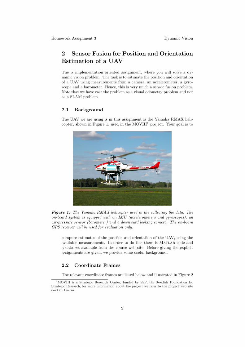
The UAV we are using is in this assignment is the Yamaha RMAX heli-copter, shown in Figure 1, used in the MOVIII1 project. Your goal is to
Figure 1: The Yamaha RMAX helicopter used in the collecting the data. Theon-board system is equipped with an IMU (accelerometers and gyroscopes), anair-pressure sensor (barometer) and a downward looking camera. The on-boardGPS receiver will be used for evaluation only.
compute estimates of the position and orientation of the UAV, using theavailable measurements. In order to do this there is Matlab code anda data-set available from the course web site. Before giving the explicitassignments are given, we provide some useful background.
2.2 Coordinate Frames
The relevant coordinate frames are listed below and illustrated in Figure 21MOVIII is a Strategic Research Center, funded by SSF, the Swedish Foundation for
Strategic Research, for more information about the project we refer to the project web sitemoviii.liu.se.
2
Homework Assignment 3 Dynamic Vision
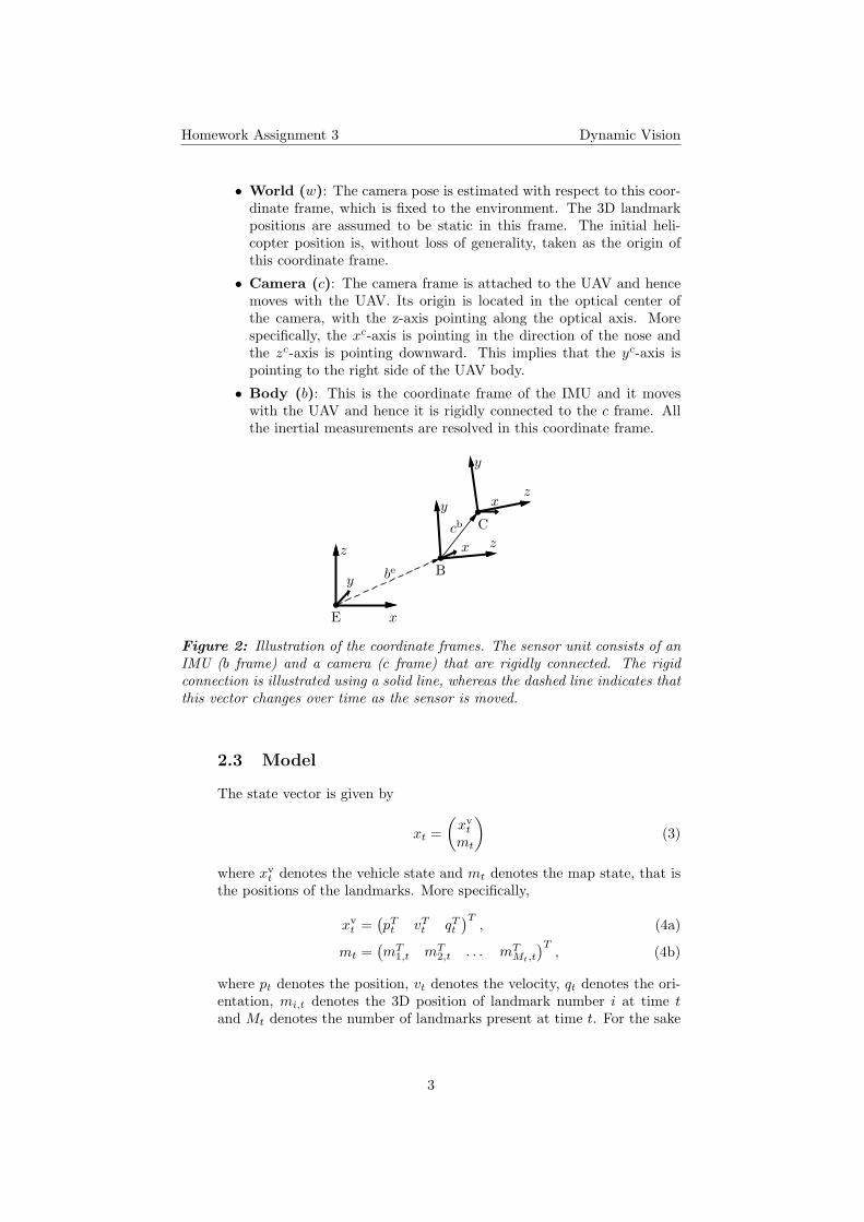
• World (w): The camera pose is estimated with respect to this coor-dinate frame, which is fixed to the environment. The 3D landmarkpositions are assumed to be static in this frame. The initial heli-copter position is, without loss of generality, taken as the origin ofthis coordinate frame.
• Camera (c): The camera frame is attached to the UAV and hencemoves with the UAV. Its origin is located in the optical center ofthe camera, with the z-axis pointing along the optical axis. Morespecifically, the xc-axis is pointing in the direction of the nose andthe zc-axis is pointing downward. This implies that the yc-axis ispointing to the right side of the UAV body.
• Body (b): This is the coordinate frame of the IMU and it moveswith the UAV and hence it is rigidly connected to the c frame. Allthe inertial measurements are resolved in this coordinate frame.
x
y
z x
y
z
x
y
z
be
cb
E
C
B
Figure 2: Illustration of the coordinate frames. The sensor unit consists of anIMU (b frame) and a camera (c frame) that are rigidly connected. The rigidconnection is illustrated using a solid line, whereas the dashed line indicates thatthis vector changes over time as the sensor is moved.
2.3 Model
The state vector is given by
xt =(xvt
mt
)(3)
where xvt denotes the vehicle state and mt denotes the map state, that is
the positions of the landmarks. More specifically,
xvt =
(pTt vTt qTt
)T, (4a)
mt =(mT
1,t mT2,t . . . mT
Mt,t
)T, (4b)
where pt denotes the position, vt denotes the velocity, qt denotes the ori-entation, mi,t denotes the 3D position of landmark number i at time tand Mt denotes the number of landmarks present at time t. For the sake
3
Homework Assignment 3 Dynamic Vision
of brevity we have suppressed which coordinate frame the variables areexpressed in, given here,
pt = pet , (5a)vt = vet , (5b)
qt = qbet , (5c)mt = me
t . (5d)
The dynamic model describes how the UAV and the map evolve over timeand it is given below.
pt+1
vt+1
qt+1
=
I TI 00 I 00 0 dt
ptvtqt
+
T 2
2 ITII
ua,t +
T 3
6 0T 2
2 0TI 00 T
2 S(qt)
(wa,twω,t
)
(6a)
mj,t+1 = mj,t, j = 1, . . . ,Mt, (6b)
where
wa,t ∼ N (0, Qa), (6c)wω,t ∼ N (0, Qω), (6d)
dt = I4 +T
2S(uω,t), (6e)
uω,t =
ωx,tωy,tωz,t
(6f)
S(uω,t) =
0 −ωx,t −ωy,t −ωz,tωx,t 0 ωz,t −ωy,tωy,t −ωz,t 0 ωx,tωz,t ωy,t −ωx,t 0
. (6g)
The measurement equation for the barometer is given by
yb,t =(0 0 1 01×7
)xt + et, et ∼ N (0, Rb). (7)
2.4 Data
The data contains the following data structures
• cam: Intrinsic camera parameters.
• geometry: Some constants related to the geometry of the hardware.
• info: Information about the current data.
• meas: Measurements (in SI units) from the accelerometers (ya),the gyroscopes (yw), the barometer (yhp, note that this is given asdeviation from the starting point) and the camera (yim).
• ref : The reference position from the GPS.
4
Homework Assignment 3 Dynamic Vision
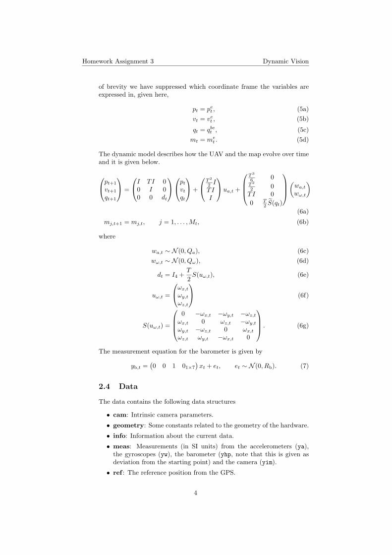
Figure 3: Orthophoto of the flight test area in Revinge (southern part of Swe-den).
The data was collected during flights in Revinge, which is a flight testarea in southern Sweden, see Figure 3 for an orthophoto of the area. Fora more detailed background on the UAV and the hardware we refer toConte (2007).
2.5 Assignments
In assignment 4−6 below you are asked to write some code missing in thecode available from the course web site. Note that the function skeletonsare available, meaning that the interfaces are already specified. Provideyour answers in terms of explanations and equations as usual, but also interms of the actual Matlab code that you have implemented. The mainscript is called experiment.
4. Predict the landmarksWrite a function
yhatf = predictLandmarks(x, par)
that takes as inputs the current state x and the par struct and com-putes predictions for the landmark positions in the image. The predictionsshould be expressed in normalized image coordinates
pn =(xnyn
)= Pn(Pc) (8a)
5
Homework Assignment 3 Dynamic Vision
where
Pc = R(Pw). (8b)
In other words, the predictions that you generate stems from a normal-ized camera. Debug hint: Use the intrinsic parameters to compute thecorresponding pixel positions and plot them in the image. They should ofcourse be quite close to the actual detections.
5. Perform state update using vision measurementsPerform measurement updates using the information available in the vi-sion measurements produced by the data association. Note that thesemeasurements will contain outliers due to erroneous associations. Thisimplies that you will also have to implement some form of outlier detec-tion. Provide a good explanation of the implemented outlier rejection.The function to be implemented is interfaced as follows
[x, P, S] = visionStateUpdate(x, P, visInnovation(:),par, visible)
Hint: You may use numerical methods in order to compute the gradients,the function Jnum is useful. Debug hint: Once this function has beencorrectly implemented it is possible to execute the entire code. Obviouslythere will not be any new landmarks initialized until the next assignmenthas been solved.
6. Search for new landmarks and initialize them in the mapSince the UAV is continuously moving, there is, at times, a need to searchfor new landmarks and to incorporate the found landmarks in the statevector.
[x, P, patches] = searchNewLandmarks(x, P, patches,yhatfp_noinit, I, visible, par)
When the above functionality has been implemented everything is in placeand you can execute the entire solution.
Besides the standard explanation of your solution you are also required todeliver plots of the Root Mean Square Error (RMSE) for the horizontalposition error, both the individual errors in the x and the y directions andthe joint error. The RMSE et is here calculated according to
et = ‖x0t − xt‖2, t = 1, . . . , N, (9)
where x0t denotes the true state (in this case the closest we can come to
the true position is provided by the GPS) and xt denotes the estimate.
7. ImprovementsGive at least 5 ways in which the implemented solution can be improved.Your suggestions should deal both with the underlying theory (e.g., themodel used and the problem formulation) and with the actual implemen-tation (e.g., structure).
6
Homework Assignment 3 Dynamic Vision
8. ReflectionNow that you have a working system it is time for some reflection. Youdo not have to provide any answers for the assignment, but if you wantthat is perfect! The least you should do is to compare the implementationthat you have just finished with the general structure of a visual odometrysystem presented during lecture 3.
3 “Gold Star” Assignment
This assignment is not mandatory. However, if you are interested this is agood way of trying out the new inverse depth parameterization provided byCivera et al. (2008). The standard way of describing the landmark positionis to use the minimal Euclidean parameterization in terms of the landmarkx, y, z position in the world coordinate frame, as we have done above. Thisparameterization has several problems; for instance it typically requires delayed(Bryson and Sukkarieh, 2005) or complicated undelayed initialization (Davisonet al., 2007). However, since we have access to a barometer in this applicationwe could to a large extent avoid these problems altogether. The reason for theproblems is that there is no way to provide a good uncertainty description ofthe fact that the depth (i.e., distance) to the landmark is unknown. An elegantapproximation which acknowledges this fact is provided by the inverse depthparameterization introduced by Civera et al. (2008). This parameterizationallows us to straightforwardly include the landmarks directly when they arefirst observed, i.e., undelayed. Furthermore, it allows us to make use of verydistant landmarks without any problems. These landmarks are of no or littleuse for inferring the camera translation, but they are very useful when it comesto the camera orientation.
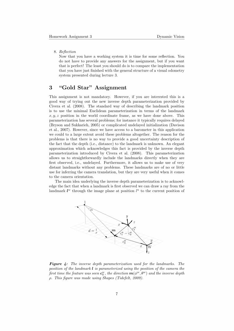
The main idea underlying the inverse depth parameterization is to acknowl-edge the fact that when a landmark is first observed we can draw a ray from thelandmark lw through the image plane at position ln to the current position of
x
y
z
x
y
z
α
d = 1ρ
m cwt
cw0
cwt − cw
0
W
l
Figure 4: The inverse depth parameterization used for the landmarks. Theposition of the landmark l is parameterized using the position of the camera thefirst time the feature was seen cw0 , the direction m(φw, θw) and the inverse depthρ. This figure was made using Shapes (Tidefelt, 2009).
7
Homework Assignment 3 Dynamic Vision
the camera’s optical center cw0 . This results in the following parameterizationof the landmark
lw = cw0 +1ρ
cosφw cos θw
cosφw sin θw
sinφw
︸ ︷︷ ︸
m(φw,θw)
, (10)
where ρ denotes the depth to the feature and the direction to the landmarkis described using spherical coordinates φw and θw, i.e., the azimuth and theelevation, respectively. This leads to the following state vector describing theposition of a landmark
xl =((cw0 )T θw φw ρ
)T ∈ R6. (11)
For a graphical illustration of the parameterization (10), see Fig. 4.The task is to replace the Euclidean (x, y, z) parameterization used in the
present solution with the inverse depth parameterization briefly introducedabove.
References
Bryson, M. and Sukkarieh, S. (2005). Bearings-only SLAM for an airbornevehicle. In Proceedings of the Australasian Conference on Robotics and Au-tomation, Sydney, Australia.
Civera, J., Davison, A. J., and Montiel, J. M. M. (2008). Inverse depth parame-terization for monocular SLAM. IEEE Transactions on Robotics, 24(5):932–945.
Conte, G. (2007). Navigation Functionalities for an Autonomous UAV Heli-copter. Licentiate Thesis No 1307, Department of Computer and InformationScience, Linkoping University, Sweden.
Davison, A. J., Reid, I., Molton, N., and Strasse, O. (2007). MonoSLAM: Real-time single camera SLAM. IEEE Transactions on Patterns Analysis andMachine Intelligence, 29(6):1052–1067.
Ma, Y., Soatto, S., Kosecka, J., and Sastry, S. S. (2006). An invitation to 3-Dvision – from images to geometric models. Interdisciplinary Applied Mathe-matics. Springer.
Tidefelt, H. (2009). The shapes language. lang-shapes.sourceforge.net/, Lastaccessed on February 8, 2009.
8