Embed Size (px)
Citation preview
55:041 Electronic Circuits. The University of Iowa. Fall 2014.
Homework Assignment 03
Question 1 (2 points each unless noted otherwise)
1. A 9-V dc power supply generates 10 W in a resistor. What peak-to-peak amplitude should an ac source have to generate the same power in the resistor?
(a) 12.73 V (b) 25.5 V (c) 18 V (d) 12.73 V Answer: The ac source’s effective (or rms) value should also be 9 V. This measn the peak value should be 9√2 V, so the peak-to-peak value should be 18√2 = 25.5 V, so the answer is (b).
2. In the circuit, 𝑉1 = 1.5 V, 𝑉2 = 2.5 V, and all the resistors have value 20K. The output voltage is (a) −4.5 V (b) +4.5 V (c) −4 V (d) −0.5 V (e) +0.5 V
Answer: This is a summing inverter with 𝑉𝑜𝑢𝑡 = −𝑉1(𝑅2 𝑅1⁄ ) − 𝑉2(𝑅2 𝑅1⁄ ). Since all the resistors have same value, 𝑉𝑜𝑢𝑡 = −𝑉1 − 𝑉2 = −4 V, so (c) is the answer.
3. What is the 3-dB bandwidth of the circuit below?
(a) ≈ 8 kHz (b) 31.83 kHz (c) 15.92 kHz (d) 100 kHz
Answer: The capacitor sees an equivalent resistance 𝑅 = 𝑅2 = 10K (the current source has infinite internal resistance) and the time-constant is 𝜏 = 𝑅𝐶 = 10 𝜇s, so that the bandwidth is 1 (2𝜋𝜏) = 15.92 kHz⁄ , and (c) is the answer.
1
55:041 Electronic Circuits. The University of Iowa. Fall 2014.
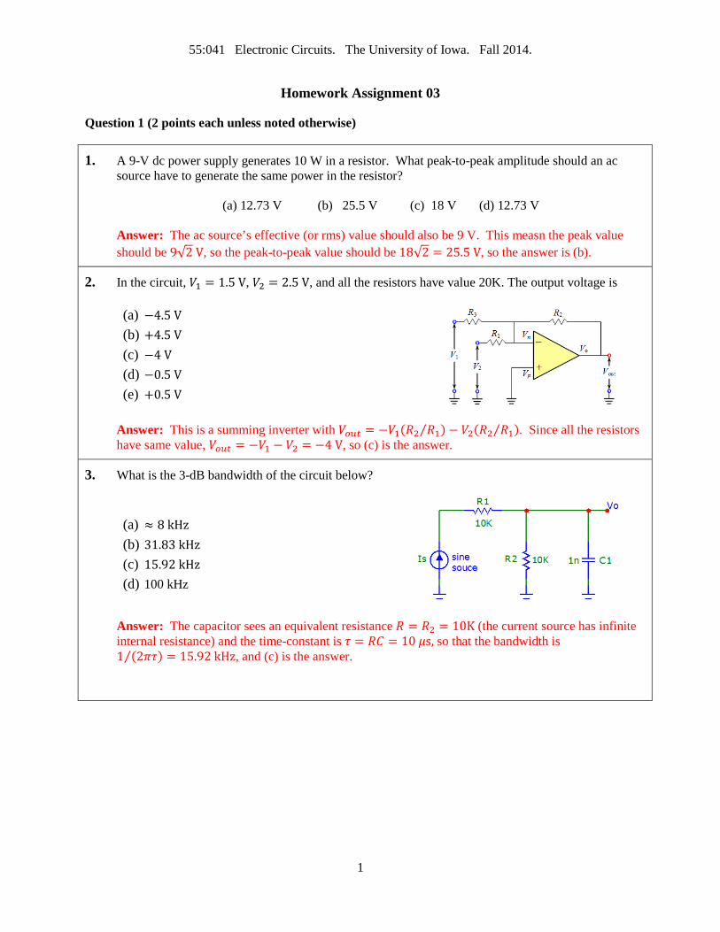
4. What is the 3-dB bandwidth of the amplifier shown below if 𝑟𝜋 = 2.5K, 𝑟𝑜 = 100K, 𝑔𝑚 = 40 mS, and 𝐶𝐿 = 𝐶𝐹 = 1 nF?
(a) 795.8 Hz (b) 1.59 kHz (c) 5 kHz (d) 4.71 kHz
Answer: If one turns off 𝑉𝐼, it is shorted to ground and 𝐶𝐿 is in parallel with 𝐶𝐹 so the effective capacitance is 2 nF. This capacitor sees an equivalent resistance 𝑟𝑜 = 100K. (If one turns off 𝑉𝐼, 𝑔𝑚𝑣𝜋 = 0, and the current source is effectively removed from the circuit.) The time-constant is 𝜏 = 𝑅𝐶 = (2 nF)(100K) = 200 𝜇s. The bandwidth is 1 (2𝜋𝜏) = 795.8 Hz⁄ , so the answer is (a).
5. The voltage gain of the amplifier shown is
(e) ≈ −5.7 (f) ≈ 5.7 (g) ≈ 6.77 (h) ≈ 13.4
Answer: 𝐴𝑣 = −𝑅𝑓 𝑅1⁄ = 68K 12K⁄ = 5.7, so the answer is (a)
6. The output of the circuit shown is
(a) Sine wave with frequency 𝜔 rad/s (b) Square wave with frequency 𝜔 2𝜋⁄ Hz (c) Triangular wave with frequency 𝜔 rad/s (d) Need additional information
Answer: With no feedback, the circuit is highly non-linear and operates as a comparator, comparing the input amplitude against 0 V. The output is a square wave for frequency 𝜔 2𝜋⁄ Hz, so the answer is (b)
2
55:041 Electronic Circuits. The University of Iowa. Fall 2014.
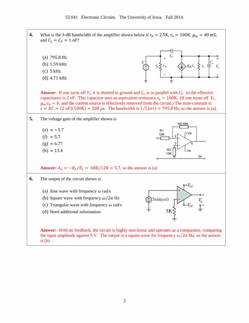
7. In the circuit shown, the output voltage is
(a) 5(1 + 8 2⁄ ) = 25 V (b) 5(8 2⁄ ) = 20 V (c) ≈ 15 V (d) ≈ −15 V (e) (8 2⁄ ) = 120 V
Answer: This is a non-inverting amplifier with gain (1 + 8 2⁄ ) = 5, so with a 5-V input the output should be 25 V. However, the op-amp is powered by a +15-V power supply, so that the output will be clamped to a value close to +15 V, so the answer is (c).
8. An engineer designs a MOSFET-based class-AB amplifier to deliver 6.25 W (sinusoidal) signal power to a 4 Ω resistive load. What is the required peak-to-peak voltage swing across the load? Answer: 𝑃 = 𝑉𝑟𝑚𝑠
2 𝑅⁄ , so that 𝑉𝑟𝑚𝑠 = 5 V, so that 𝑉𝑝𝑝 = 14.14 V
9. An engineer designs a MOSFET-based class-AB amplifier to deliver 6.25 W (sinusoidal) signal power to a 4 Ω resistive load. What is the required peak-to-peak voltage swing across the load? (a) 9.77 V (b) 19.53 V (c) 10 V (d) 14.14 V (e) 7.07 V Answer: 𝑃 = 𝑉𝑟𝑚𝑠
2 𝑅⁄ , so that 𝑉𝑟𝑚𝑠 = 5 V, so that 𝑉𝑝𝑝 = 14.14 V, so (d).
10. Consider a linear power supply consisting of a transformer, a full-wave, 4-diode bridge rectifier, smoothing capacitor, and a load current 1.2 A. By what percentage will the ripple voltage increase if the load current increases to 1.5 A?
a) 100 % (b) 25% (c) Stay the same (d) 50%
Answer: 25%
11. Consider a linear power supply consisting of a transformer, a full-wave, a bridge rectifier and a smoothing capacitor. Increasing the smoothing capacitor by 50% will
(a) Reduce ripple voltage by 50% and increase maximum inrush current by 50% (b) Reduce both ripple voltage and maximum inrush current by 50% (c) Reduce ripple voltage by 50% and leave maximum inrush current unaffected (d) Reduce ripple voltage by 50% and increase maximum inrush current by 100%
Answer: (a)
3
55:041 Electronic Circuits. The University of Iowa. Fall 2014.
12. Consider a linear power supply consisting of a transformer, a half-wave, 1-diode rectifier, and a smoothing capacitor. The rectifier diode is now replaced with a bridge (4-diode) rectifier. Neglecting the diodes’ turn-on voltages, the ripple voltage will:
a) Decrease by a factor 4 b) Decrease by a factor 2 c) Stay the same d) Increase by a factor 4
Answer: (b)
13. In an ac series RC circuit, if 20 VAC is measured across the resistor and 40 VAC is measured across the capacitor, the magnitude of the applied voltage is:
(a) ≈ 60 VAC (b) ≈ 55 VAC (c) ≈ 50 VAC (d) ≈ 45 VAC
Answer: The applied voltage is 𝑉𝐼𝑁 = 𝑉𝑅 + 𝑗𝑉𝐶, so that |𝑉𝐼𝑁| = �𝑉𝑅2 + 𝑉𝐶2 = √2,000 ≈ 45 VAC.
Thus (d) is the answer.
14. What is the magnitude of the current phase angle for a 5.6 𝜇F capacitor and a 50-Ω resistor in series with a 1.1 kHz, 5 VAC source?
(a) 72.9° (b) 62.7° (c) 27.3° (d) 17.1 Answer: The impedance of the RC circuit is = 𝑅 − 1 𝑗2𝜋𝑓𝐶⁄ = 50 − 𝑗25.84 Ω. The magnitude of the phase angle is |tan−1(−25.84 50⁄ )| = 27.3°. Thus, (c) is the answer.
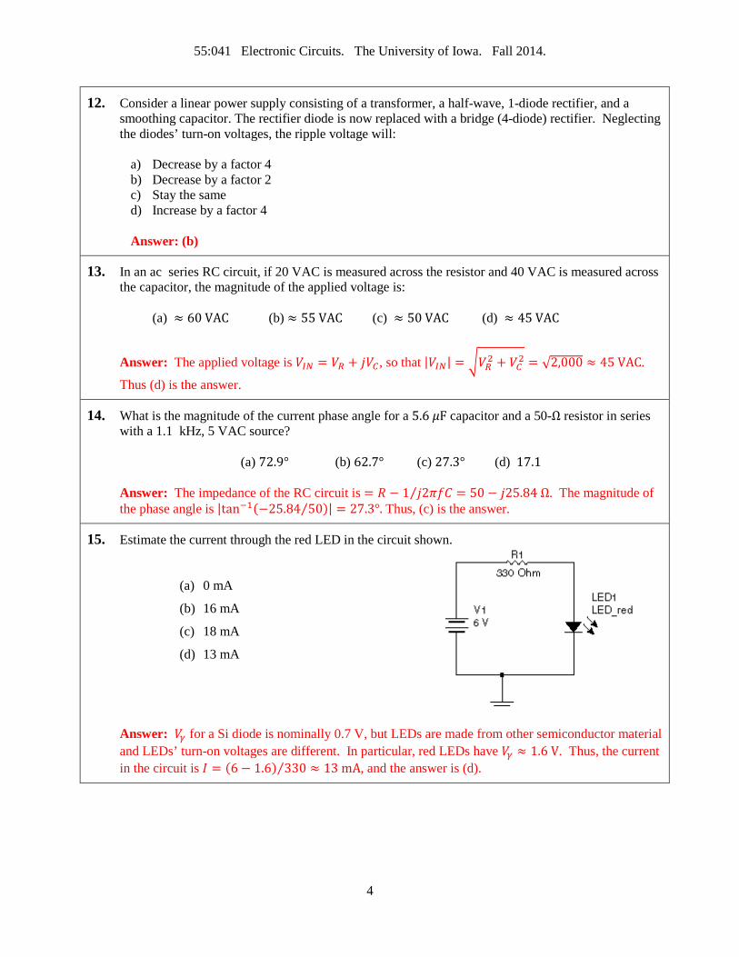
15. Estimate the current through the red LED in the circuit shown.
(a) 0 mA
(b) 16 mA
(c) 18 mA
(d) 13 mA
Answer: 𝑉𝛾 for a Si diode is nominally 0.7 V, but LEDs are made from other semiconductor material and LEDs’ turn-on voltages are different. In particular, red LEDs have 𝑉𝛾 ≈ 1.6 V. Thus, the current in the circuit is 𝐼 = (6 − 1.6) 330 ≈ 13 mA⁄ , and the answer is (d).
4
55:041 Electronic Circuits. The University of Iowa. Fall 2014.
16. A diode for which you change the reverse bias voltage to change the junction capacitance is called ___________ diode and these are used in tuned circuits.
(a) varactor (b) tunnel (c) switching (d) Zener
Answer: Option (a)
17. A filtered full-wave rectifier voltage has a smaller ripple than does a half-wave rectifier voltage for the same load resistance and capacitor values because:
(a) There is a shorter time between peaks
(b) There is a longer time between peaks
(a) The larger the ripple, the better the filtering action
(b) None of the above
Answer: Option (a).
18. The PIV across a nonconducting diode in a bridge rectifier equals approximately:
(a) half the peak (b) 2 × the peak (c) the peak (d) 4 × the peak
value of the transformer secondary voltage.
Answer: Option (c)
19. What is the current through the ideal diode?
(a) 1 mA
(b) 0.975 mA
(c) 0.942 mA
(d) 0.867 mA
Answer: For an ideal diode there is no forward voltage drop, so 𝐼 = 12 12K = 1 mA⁄ , so option (a) is the answer.
20. With a 12-V supply, a silicon diode, and a 370 Ω resistor in series, what voltage will be dropped across the diode?
(a) ≈ 0.3 V (b) ≈ 0.7 V (c) ≈ 0.9 V (d) (a) ≈ 1.4 V
Answer: Option (b)
5
55:041 Electronic Circuits. The University of Iowa. Fall 2014.
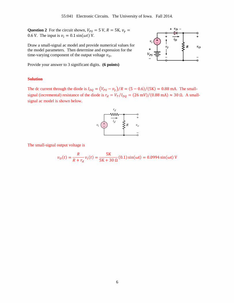
Question 2 For the circuit shown, 𝑉𝑃𝑆 = 5 V, 𝑅 = 5K, 𝑣𝛾 =0.6 V. The input is 𝑣𝑖 = 0.1 sin(𝜔𝑡) V. Draw a small-signal ac model and provide numerical values for the model parameters. Then determine and expression for the time-varying component of the output voltage 𝑣𝑂 . Provide your answer to 3 significant digits. (6 points)
Solution
The dc current through the diode is 𝐼𝐷𝑄 = �𝑉𝑃𝑆 − 𝑣𝛾� 𝑅⁄ = (5 − 0.6) (5K) = 0.88 mA⁄ . The small-signal (incremental) resistance of the diode is 𝑟𝑑 = 𝑉𝑇 𝐼𝐷𝑄 = (26 mV) (0.88 mA)⁄⁄ ≈ 30 Ω. A small-signal ac model is shown below.
The small-signal output voltage is
𝑣𝑂(𝑡) =𝑅
𝑅 + 𝑟𝑑𝑣𝑖(𝑡) =
5K5K + 30 Ω
(0.1) sin(ωt) = 0.0994 sin(ωt) V
6
55:041 Electronic Circuits. The University of Iowa. Fall 2014.
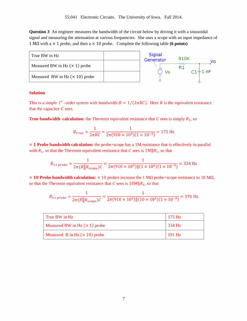
Question 3 An engineer measures the bandwidth of the circuit below by driving it with a sinusoidal signal and measuring the attenuation at various frequencies. She uses a scope with an input impedance of 1 MΩ with a × 1 probe, and then a × 10 probe. Complete the following table (6 points)
True BW in Hz
Measured BW in Hz (× 1) probe
Measured BW in Hz (× 10) probe
Solution
This is a simple 1st –order system with bandwidth 𝐵 = 1 (2𝜋𝑅𝐶)⁄ . Here 𝑅 is the equivalent resistance that the capacitor 𝐶 sees.
True bandwidth calculation: the Thevenin equivalent resistance that 𝐶 sees is simply 𝑅1, so
𝐵𝑇𝑟𝑢𝑒 =1
2𝜋𝑅𝐶=
12𝜋(910 × 103)(1 × 10⁻⁹) = 175 Hz
× 𝟏 Probe bandwidth calculation: the probe+scope has a 1M resistance that is effectively in parallel with 𝑅1, so that the Thevenin equivalent resistance that 𝐶 sees is 1M‖𝑅1, so that
𝐵×1 𝑝𝑟𝑜𝑏𝑒 =1
2𝜋(𝑅�𝑅𝑠𝑐𝑜𝑝𝑒)𝐶=
12𝜋(910 × 103)‖(1 × 10⁶)(1 × 10⁻⁹) = 334 Hz
× 𝟏𝟎 Probe bandwidth calculation: × 10 probes increase the 1 MΩ probe+scope resistance to 10 MΩ, so that the Thevenin equivalent resistance that 𝐶 sees is 10M‖𝑅1, so that
𝐵×1 𝑝𝑟𝑜𝑏𝑒 =1
2𝜋(𝑅�𝑅𝑠𝑐𝑜𝑝𝑒)𝐶=
12𝜋(910 × 103)‖(10 × 106)(1 × 10⁻⁹) = 191 Hz
True BW in Hz 175 Hz
Measured BW in Hz (× 1) probe 334 Hz
Measured B in Hz (× 10) probe 191 Hz
7
55:041 Electronic Circuits. The University of Iowa. Fall 2014.
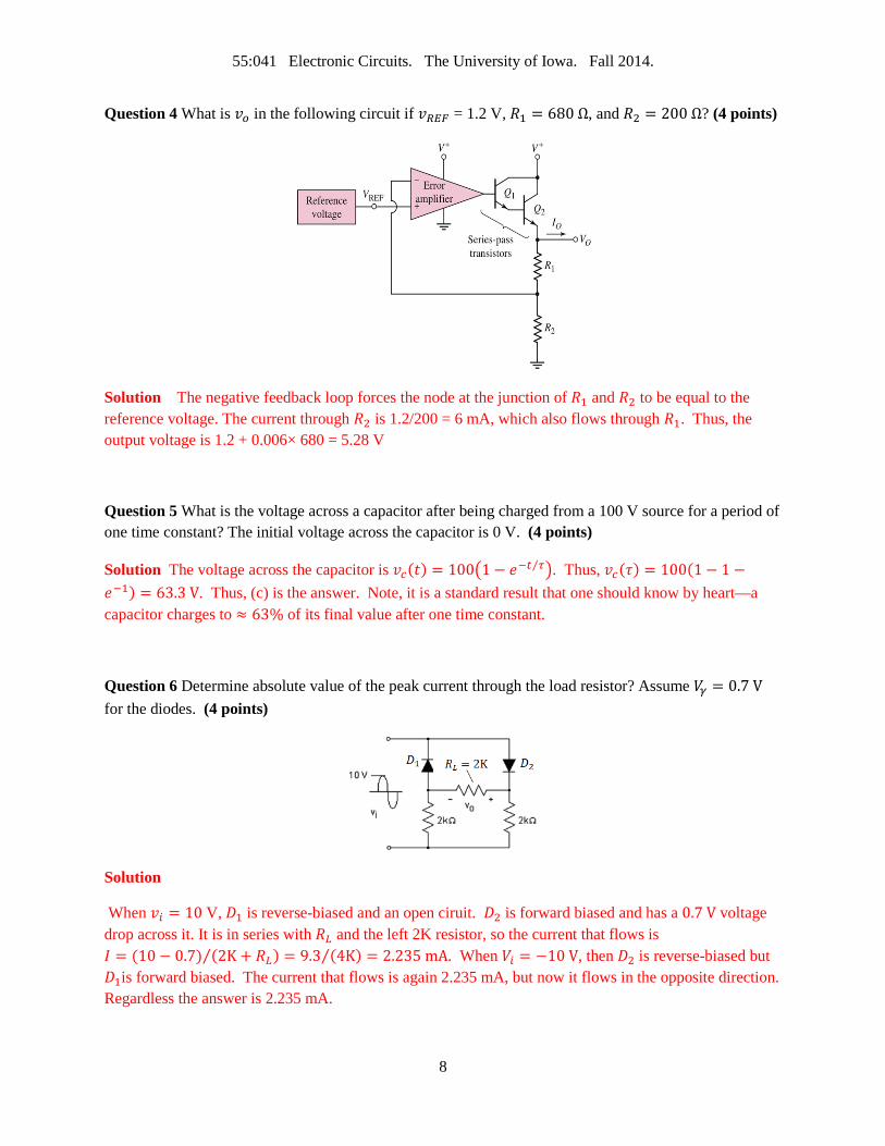
Question 4 What is 𝑣𝑜 in the following circuit if 𝑣𝑅𝐸𝐹 = 1.2 V, 𝑅1 = 680 Ω, and 𝑅2 = 200 Ω? (4 points)
Solution The negative feedback loop forces the node at the junction of 𝑅1 and 𝑅2 to be equal to the reference voltage. The current through 𝑅2 is 1.2/200 = 6 mA, which also flows through 𝑅1. Thus, the output voltage is 1.2 + 0.006× 680 = 5.28 V
Question 5 What is the voltage across a capacitor after being charged from a 100 V source for a period of one time constant? The initial voltage across the capacitor is 0 V. (4 points)
Solution The voltage across the capacitor is 𝑣𝑐(𝑡) = 100�1− 𝑒−𝑡 𝜏⁄ �. Thus, 𝑣𝑐(𝜏) = 100(1− 1 −𝑒−1) = 63.3 V. Thus, (c) is the answer. Note, it is a standard result that one should know by heart—a capacitor charges to ≈ 63% of its final value after one time constant.
Question 6 Determine absolute value of the peak current through the load resistor? Assume 𝑉𝛾 = 0.7 V for the diodes. (4 points)
Solution
When 𝑣𝑖 = 10 V, 𝐷1 is reverse-biased and an open ciruit. 𝐷2 is forward biased and has a 0.7 V voltage drop across it. It is in series with 𝑅𝐿 and the left 2K resistor, so the current that flows is 𝐼 = (10 − 0.7) (2K + 𝑅𝐿) = 9.3 (4K) = 2.235 mA⁄⁄ . When 𝑉𝑖 = −10 V, then 𝐷2 is reverse-biased but 𝐷1is forward biased. The current that flows is again 2.235 mA, but now it flows in the opposite direction. Regardless the answer is 2.235 mA.
8
55:041 Electronic Circuits. The University of Iowa. Fall 2014.
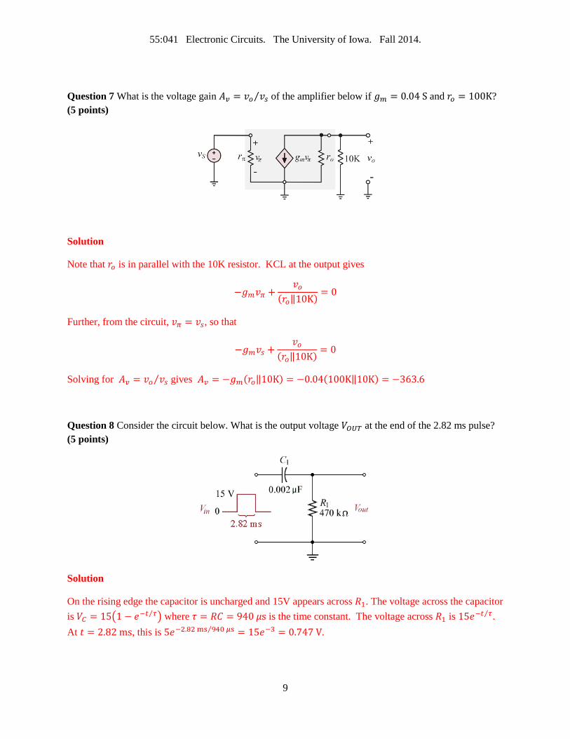
Question 7 What is the voltage gain 𝐴𝑣 = 𝑣𝑜 𝑣𝑠⁄ of the amplifier below if 𝑔𝑚 = 0.04 S and 𝑟𝑜 = 100K? (5 points)
Solution
Note that 𝑟𝑜 is in parallel with the 10K resistor. KCL at the output gives
−𝑔𝑚𝑣𝜋 +𝑣𝑜
(𝑟𝑜‖10K) = 0
Further, from the circuit, 𝑣𝜋 = 𝑣𝑠, so that
−𝑔𝑚𝑣𝑠 +𝑣𝑜
(𝑟𝑜‖10K) = 0
Solving for 𝐴𝑣 = 𝑣𝑜 𝑣𝑠⁄ gives 𝐴𝑣 = −𝑔𝑚(𝑟𝑜‖10K) = −0.04(100K‖10K) = −363.6
Question 8 Consider the circuit below. What is the output voltage 𝑉𝑂𝑈𝑇 at the end of the 2.82 ms pulse? (5 points)
Solution
On the rising edge the capacitor is uncharged and 15V appears across 𝑅1. The voltage across the capacitor is 𝑉𝐶 = 15�1 − 𝑒−𝑡 𝜏⁄ � where 𝜏 = 𝑅𝐶 = 940 𝜇s is the time constant. The voltage across 𝑅1 is 15𝑒−𝑡 𝜏⁄ . At 𝑡 = 2.82 ms, this is 5𝑒−2.82 ms 940 𝜇s⁄ = 15𝑒−3 = 0.747 V.
9
55:041 Electronic Circuits. The University of Iowa. Fall 2014.
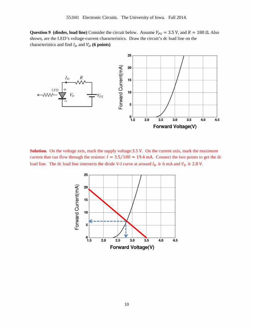
Question 9 (diodes, load line) Consider the circuit below. Assume 𝑉𝑃𝑆 = 3.5 V, and 𝑅 = 180 Ω. Also shown, are the LED’s voltage-current characteristics. Draw the circuit’s dc load line on the characteristics and find 𝐼𝐷 and 𝑉𝐷 (6 points)
Solution. On the voltage axis, mark the supply voltage:3.5 V. On the current axis, mark the maximum current that can flow through the resistor: 𝐼 = 3.5 180⁄ = 19.4 mA. Connect the two points to get the dc load line. The dc load line intersects the diode V-I curve at around 𝐼𝐷 ≅ 6 mA and 𝑉𝐷 ≅ 2.8 V.
10
55:041 Electronic Circuits. The University of Iowa. Fall 2014.
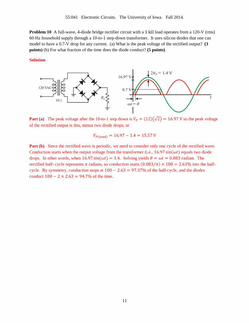
Problem 10 A full-wave, 4-diode bridge rectifier circuit with a 1 kΩ load operates from a 120-V (rms) 60-Hz household supply through a 10-to-1 step-down transformer. It uses silicon diodes that one can model to have a 0.7-V drop for any current. (a) What is the peak voltage of the rectified output? (3 points) (b) For what fraction of the time does the diode conduct? (5 points)
Solution
Part (a) The peak voltage after the 10-to-1 step down is 𝑉𝑃 = (12)�√2� = 16.97 V so the peak voltage of the rectified output is this, minus two diode drops, or
𝑉𝑃(𝑙𝑜𝑎𝑑) = 16.97− 1.4 = 15.57 V
Part (b) Since the rectified wave is periodic, we need to consider only one cycle of the rectified wave. Conduction starts when the output voltage from the transformer (i.e., 16.97 sin(𝜔𝑡) equals two diode drops. In other words, when 16.97 sin(𝜔𝑡) = 1.4. Solving yields 𝜃 = 𝜔𝑡 = 0.083 radian. The rectified half- cycle represents 𝜋 radians, so conduction starts (0.083 𝜋⁄ ) × 100 = 2.63% into the half-cycle. By symmetry, conduction stops at 100 − 2.63 = 97.37% of the half-cycle, and the diodes conduct 100 − 2 × 2.63 = 94.7% of the time.
11
55:041 Electronic Circuits. The University of Iowa. Fall 2014.
Problem 11 An engineer designs a power supply that consists of a transformer, a full-wave, 4-diode bridge rectifier and a smoothing capacitor. She designed the supply to operate in the U.S. where the power line (mains) frequency and voltage is 60 Hz and 120 V respectively. The ripple voltage at full load is 20 mV. Estimate the ripple voltage when the unmodified supply is used in regions of Japan where the corresponding values are 50 Hz and 100 V respectively. Assume that the equivalent load resistance stays the same. (5 points)
Solution
The ripple voltage for a full-wave, 4-diode bridge rectifier is (see chapter 2 of 4th edition of Neaman’s text book):
𝑉𝑟 =𝑉𝑀
2𝑓𝑅𝐶
Here 𝑉𝑀 is the maximum (peak) voltage of the input sine wave, 𝑓 is the frequency, 𝐶 is the capacitance of the smoothing capacitor, and 𝑅 is the load resistance. With new mains voltage 𝑉𝑀′ = (100 120⁄ )𝑉𝑀 and new mains frequency 𝑓′ = (50 60⁄ )𝑓, the new ripple voltage is
𝑉𝑟′ =𝑉𝑀′
2𝑓′𝑅𝐶=
(100 120⁄ )𝑉𝑀2(50 60⁄ )𝑓𝑅𝐶
= �100120
� � 6050� �
𝑉𝑀2𝑓𝑅𝐶
� = �𝑉𝑀
2𝑓𝑅𝐶� = 20 mV
That is, the ripple voltage will not change.
12
55:041 Electronic Circuits. The University of Iowa. Fall 2014.
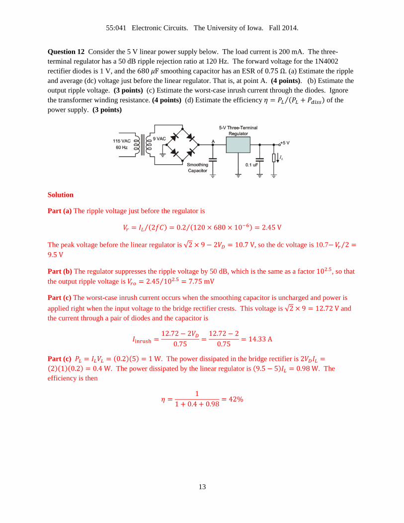
Question 12 Consider the 5 V linear power supply below. The load current is 200 mA. The three-terminal regulator has a 50 dB ripple rejection ratio at 120 Hz. The forward voltage for the 1N4002 rectifier diodes is 1 V, and the 680 𝜇F smoothing capacitor has an ESR of 0.75 Ω. (a) Estimate the ripple and average (dc) voltage just before the linear regulator. That is, at point A. (4 points). (b) Estimate the output ripple voltage. (3 points) (c) Estimate the worst-case inrush current through the diodes. Ignore the transformer winding resistance. (4 points) (d) Estimate the efficiency 𝜂 = 𝑃𝐿 (𝑃𝐿 + 𝑃𝑑𝑖𝑠𝑠)⁄ of the power supply. (3 points)
Solution
Part (a) The ripple voltage just before the regulator is
𝑉𝑟 = 𝐼𝐿 (2𝑓𝐶)⁄ = 0.2 (120 × 680 × 10−6) = 2.45 V⁄
The peak voltage before the linear regulator is √2 × 9 − 2𝑉𝐷 = 10.7 V, so the dc voltage is 10.7−𝑉𝑟 2⁄ =9.5 V
Part (b) The regulator suppresses the ripple voltage by 50 dB, which is the same as a factor 102.5, so that the output ripple voltage is 𝑉𝑟𝑜 = 2.45 102.5 = 7.75 mV⁄
Part (c) The worst-case inrush current occurs when the smoothing capacitor is uncharged and power is applied right when the input voltage to the bridge rectifier crests. This voltage is √2 × 9 = 12.72 V and the current through a pair of diodes and the capacitor is
𝐼inrush =12.72− 2𝑉𝐷
0.75=
12.72− 20.75
= 14.33 A
Part (c) 𝑃𝐿 = 𝐼𝐿𝑉𝐿 = (0.2)(5) = 1 W. The power dissipated in the bridge rectifier is 2𝑉𝐷𝐼𝐿 =(2)(1)(0.2) = 0.4 W. The power dissipated by the linear regulator is (9.5 − 5)𝐼𝐿 = 0.98 W. The efficiency is then
𝜂 =1
1 + 0.4 + 0.98= 42%
13

55:041 Electronic Circuits. The University of Iowa. Fall 2014.
Question 13 Determine VD for the circuit shown to within 0.01 V. This is not necessarily a Si diode so you can’t assume 𝑉𝐷 = 0.7 V. Rather, use the diode equation 𝐼𝐷 = 𝐼𝑆�𝑒𝑉𝐷 𝑉𝑇⁄ − 1� and assume that IS = 10-13 A and 𝑇 = 300K. Use the bisection numerical method with the initial bracket values 𝑉𝐿 = 0.6 V and 𝑉𝐻 = 0.65 V. Organize you values neatly in a table. (8 points)
Solution
KVL gives −𝑉𝑃𝑆 + 𝐼𝐷𝑅 + 𝑉𝐷 = 0 For the diode
𝐼𝐷 = 𝐼𝑆�𝑒𝑉𝐷 𝑉𝑇⁄ − 1� Eq. 1 Substituting this into the KVL equation and reorganizing gives
𝑉𝑃𝑆 = 𝑅𝐼𝑠�𝑒𝑉𝐷 𝑉𝑇⁄ − 1� + 𝑉𝐷
𝑉𝐷 = 5 − (2 × 10³)(1 × 10⁻¹³)�𝑒𝑉𝐷 0.026⁄ − 1� Eq. 2
Now try different values for 𝑉𝐷 substituting in the RHS of the equation above.
Iteration 𝑉𝐿 𝑉𝐻 𝑉𝐷 = (𝑉𝐻 − 𝑉𝐿) 2⁄ 𝑉𝐷′ which is from RHS of Equation 2 𝑉𝐷′−𝑉𝐷
1 0.60000 0.65000 0.62500 -0.50556 -1.1306 2 0.60000 0.62500 0.61250 1.59587 0.9834 3 0.61250 0.62500 0.61875 0.67084 0.0521 4 0.61875 0.62500 0.62187 0.11795 -0.5039 5 0.61875 0.62187 0.62031 0.40270 -0.2176 6 0.61875 0.62031 0.61953 0.53878 -0.0807 7 0.61875 0.61953 0.61914 0.60531 -0.0138 8 0.61875 0.61914 0.61895 0.63820 0.0193 9 0.61895 0.61914 0.61904 0.62178 0.0027
% Matlab Script R = 2e3; Is = 1e-13; VT = 0.026; VH = 0.65; VL = 0.6; for i = 1:100 VD = (VH+VL)/2; VDP = 5 - Is*R*(exp(VD/VT)-1); err = VDP-VD; s = sprintf('%d, %7.5f, %7.5f, %7.5f, %7.5f, %6.4f',i,VL,VH,VD,VDP,err); disp(s) if (err < 0) VH = VD; else VL = VD; end if (abs(err) < 0.01) break; end end
14