Embed Size (px)
Citation preview
Zainul Ihsan, Klaus Solbach
High Frequency Engineering Department
University Duisburg-Essen Germany
Presented at German Microwave Conference 2008
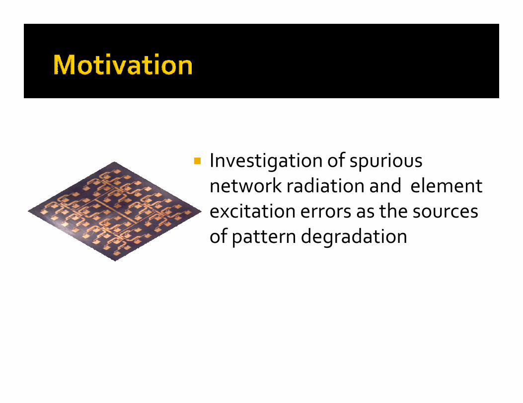
� Investigation of spurious
network radiation and element
excitation errors as the sourcesexcitation errors as the sources
of pattern degradation
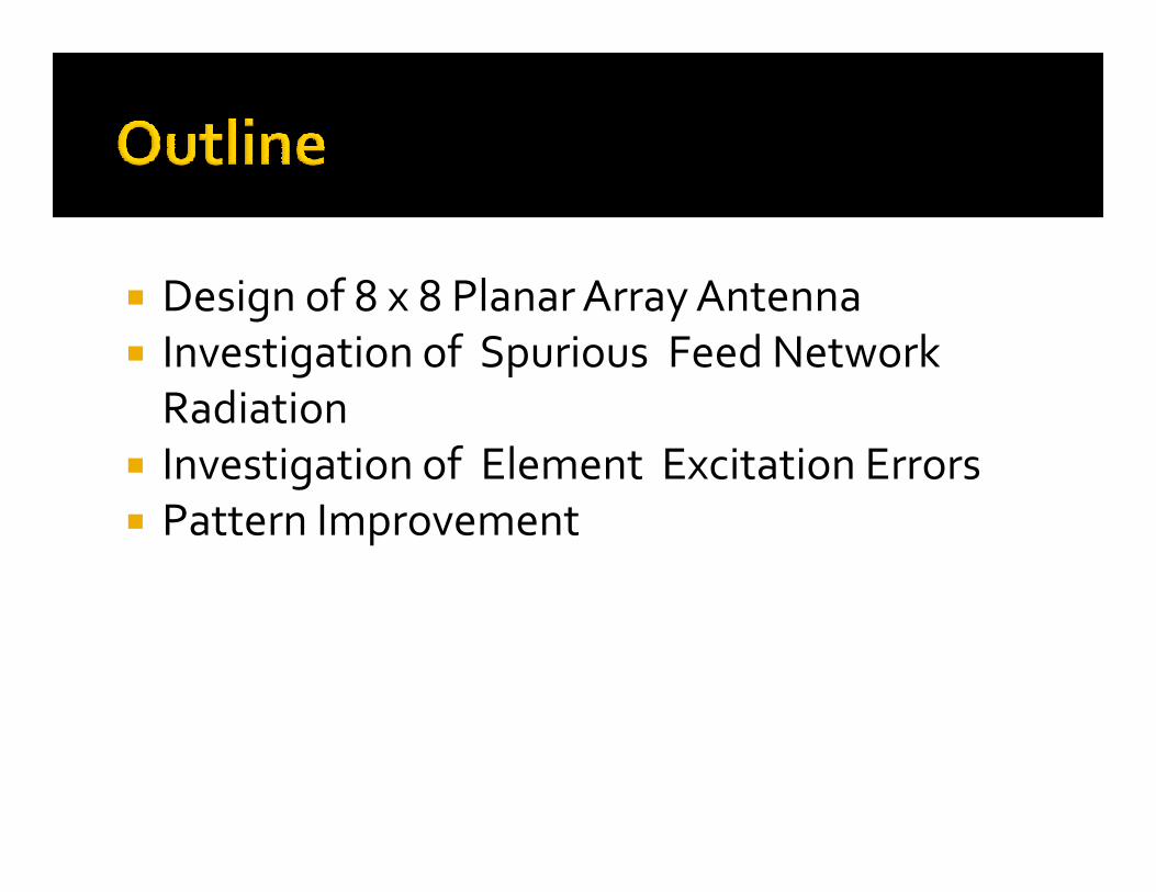
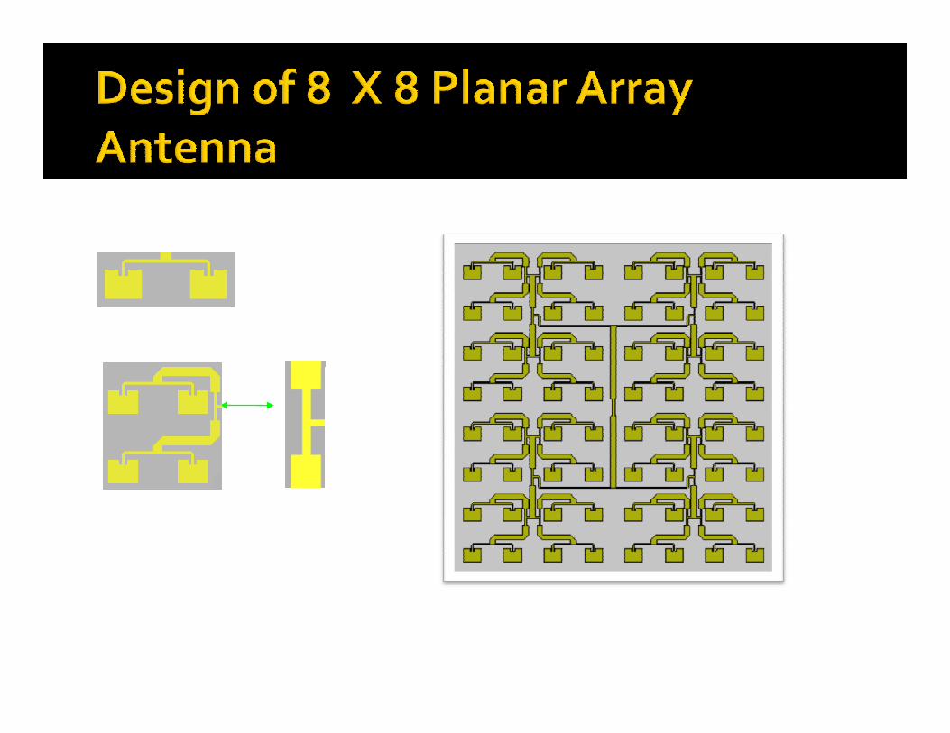
� Design of 8 x 8 Planar Array Antenna
� Investigation of Spurious Feed Network
Radiation
Investigation of Element Excitation Errors� Investigation of Element Excitation Errors
� Pattern Improvement
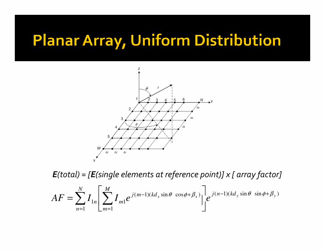
E(total) = [E(single elements at reference point)] x [ array factor]
)sinsin)(1(
1
)cossin)(1(
1
1
1
yyxxkdnj
M
m
kdmj
m
N
n
n eeIIAFβφθβφθ +−
=
+−
=
= ∑∑
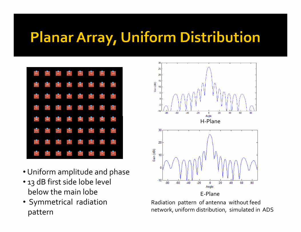
• Uniform amplitude and phase
• 13 dB first side lobe level
below the main lobe
• Symmetrical radiation
pattern
Radiation pattern of antenna without feed
network, uniform distribution, simulated in ADS
H-Plane
E-Plane
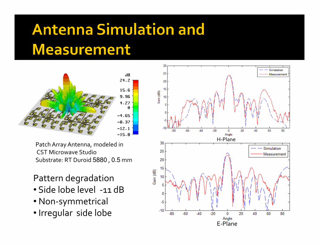
Pattern degradation
• Side lobe level -11 dB
• Non-symmetrical
• Irregular side lobe
H-Plane
E-Plane
Patch Array Antenna, modeled in
CST Microwave Studio
Substrate: RT Duroid 5880 , 0.5 mm
e
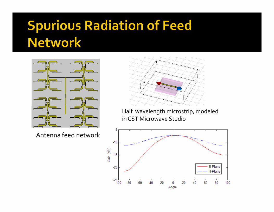
Antenna feed network
Half wavelength microstrip, modeled
in CST Microwave Studio
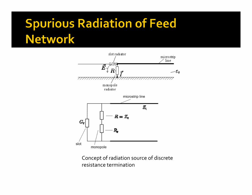
Concept of radiation source of discrete
resistance termination

Feed network terminated by resistance,
modeled in CST Microwave StudioBlow up network terminated
H-Plane radiation pattern of antenna and feed network
modeled in CST Microwave StudioBlow up network terminated
by resistance
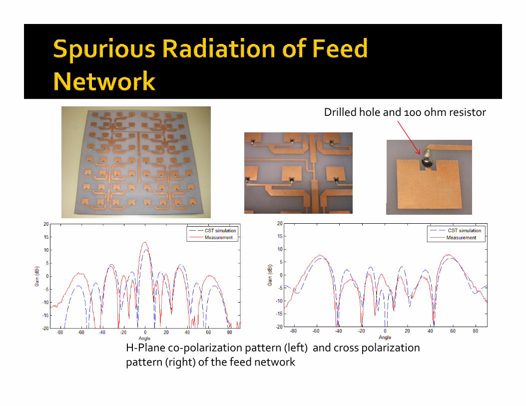
Drilled hole and 100 ohm resistor
H-Plane co-polarization pattern (left) and cross polarization
pattern (right) of the feed network
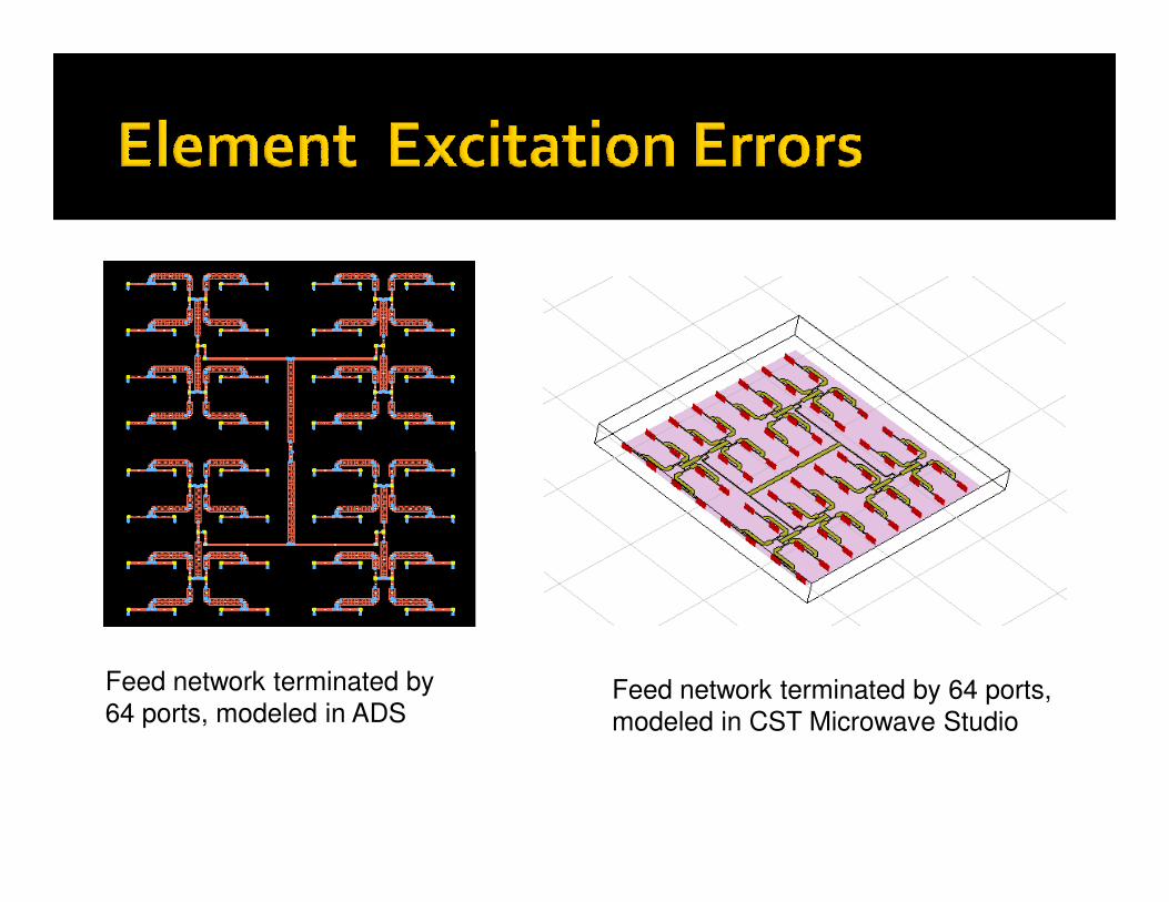
Feed network terminated by
64 ports, modeled in ADSFeed network terminated by 64 ports,
modeled in CST Microwave Studio
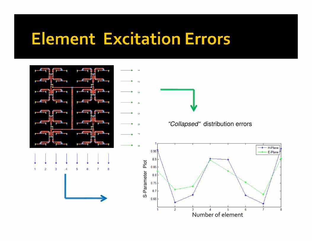
“Collapsed“ distribution errors“Collapsed“ distribution errors
S-P
ara
me
ter
Plo
t
Number of element

Patch array without feed
network, excitation included
error,modeled in ADS
Radiation pattern of the antenna and patch
array without feed network
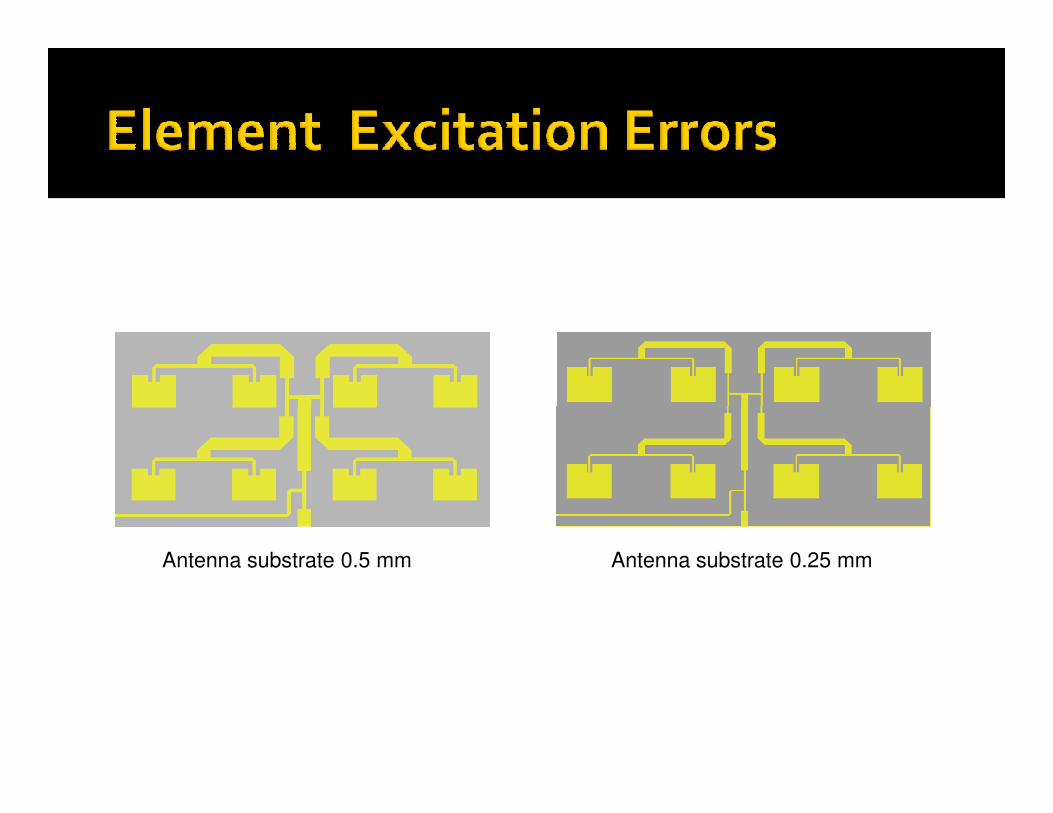
Antenna substrate 0.5 mm Antenna substrate 0.25 mm
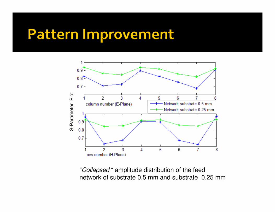
Para
mete
r P
lot
“Collapsed “ amplitude distribution of the feed
network of substrate 0.5 mm and substrate 0.25 mm
S-P
ara
mete
r P
lot
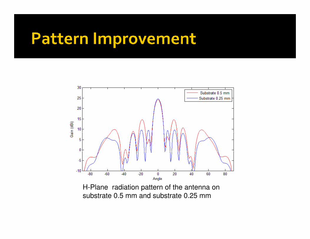
H-Plane radiation pattern of the antenna on
substrate 0.5 mm and substrate 0.25 mm
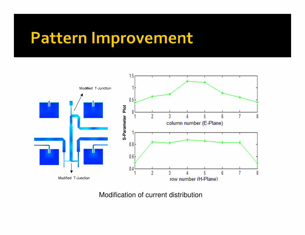
Param
ete
r P
lot
Modification of current distribution
S-P
aram
ete
r P
lot
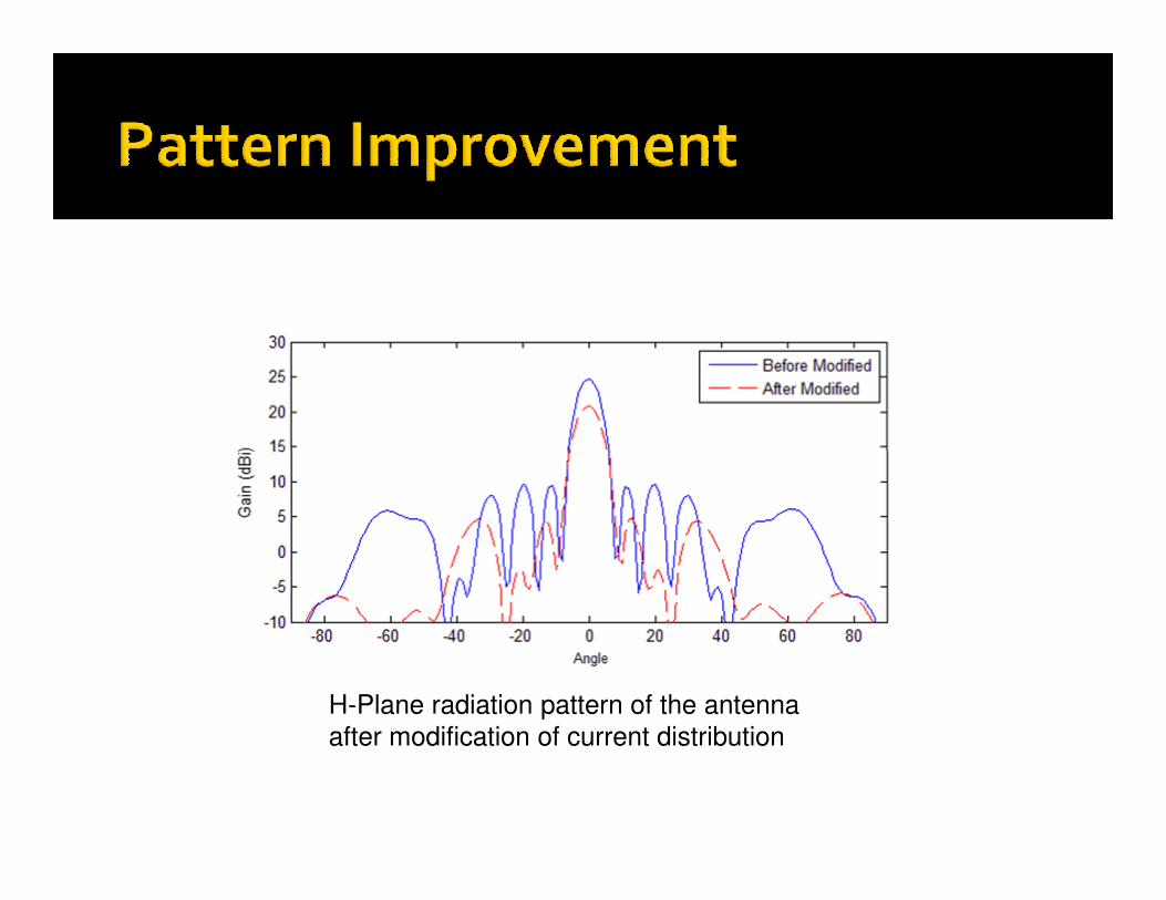
H-Plane radiation pattern of the antenna
after modification of current distribution
1.Separation of the major sources of patterndegradation :
� Element excitation errors (more dominantin our case).in our case).
� Spurious radiation from the feed network .2.Improvement,verified with simulations and
experiments , can be done by:
� Reduction of line width.
� Reduction of substrate thickness.
“ To be the best scientist, let us focus our attention
like radiation of high gain antenna “
Thank youThank you
12nd March 2008
Hamburg, Germany