Embed Size (px)
Citation preview

GOVERNMENT ENGINEERING COLLEGE, VALSAD MECHANICAL ENGINEERING DEPARTMENT
CERTIFICATE
This is to certify that Mr/Miss________________________________________________________________ of
____________________ Engineering Branch, Sem-II, Enrollment No.__________________________, has
satisfactorily completed his/her term work for the subject Basic Mechanical
Engineering (3110006) during even term-2020.
Date : Sign of Faculty Head of the Department

GOVERNMENT ENGINEERING COLLEGE, VALSAD MECHANICAL ENGINEERING DEPARTMENT
INDEX
Subject: Basic Mechanical Engineering (3110006)
Sr. No.
TITLE DATE GRADE SIGN OF
FACULTY
1
Study of steam boilers
2 Study of boiler mountings and accessories
3 Study of two and four stroke petrol and diesel engines
4 Determine brake thermal efficiency of an i. C. Engine
5 Study of different types of air compressors
6 Study of refrigeration and air conditioning
7 Study of different types clutches coupling and brakes
8 Study of power transmission drives

GOVERNMENT ENGINEERING COLLEGE, VALSAD MECHANICAL ENGINEERING DEPARTMENT
PRACTICAL 1: STUDY OF STEAM BOILERS
Objective:
1. Definition and application of boiler.
2. Classification of boiler.
3. Understanding the working of different boilers
4. Selection of boiler
Theory:
The function of a boiler is to transfer heat produced by burning of fuel to water and thus to
produce steam at desired temperature and pressure. Steam boiler may be defined as “A closed pressure
vessel in which, steam is generated with capacity exceeding 25 liters, gauge pressure greater than or
equal to 1kg/cm2, and water is heated at 100⁰C or above”.
Application of steam generated from boiler:
To operate steam engines and steam turbines
For industrial process work (e.g. drying process)
For heating purpose
Classification of Boiler:
Fire tube (smoke tube) and water tube
Internally fired and externally fired
According to number of tubes
According to types of fuels used
According to pressure at which steam generated
According to position of drum/shell
Stationary and portable
Natural circulation and Forced circulation
General terms used in Steam Boiler
1. Cylindrical shell
It is made up of steel plates bent into cylindrical form and rewetted and welded together. The ends of
shell are closed by means of plates in different shapes. It should have sufficient capacity to contain water
and steam.
2. Combustion chamber
It is the space, generally below the boiler shell, meant for burning fuel in order to produce steam from the
water contained in the shell.
3. Grate
It is a platform, in the combustion chamber, upon which fuel is burnt. The grate consists of cast iron bars
which are spaced apart so that air can pass through them.

4. Furnace
It is a chamber formed by the space above grate and bellows the boiler shell in which combustion take
place. It is also called a Fire box.
5. Fire Hole
It is the hole through which coal is added to the furnace.
6. Ash Pit (ash pan)
It is the area in which the ash of burnt coal is collected.
7. Smoke chamber (smoke box)
The waste gases are collected here and then releases to the chimney and then to atmosphere.
8. Man Hole
It is a hole provided on to the boiler shell so that a workman can go inside the boiler for inspection.
9. Hand Holes
It is a hole provided on the shell to give to give east access for the purpose of cleaning of water tubes or
some other internal parts of boiler.
10. Mud box
It collects all impurities present in the water. It is at the bottom of the barrel or shell. These impurities are
removed time to time by help of blow off cock.
11. Steam collecting pipe
When steam leaving the boiler, it contain certain amount of water Anti-priming pipe is used to separate
water particles from the steam and to collect dry steam from boiler.
12. Mountings
These are the safety devices for the safe working of steam boiler and they are mounted on the steam
boiler like Water indicator valve, pressure gauge, fusible plug etc.
13. Accessories
These devices are used for increasing the efficiency of boilers. They are integral parts of the boiler and are
not mounted on the boiler. They include Super heater, Economizer, etc.
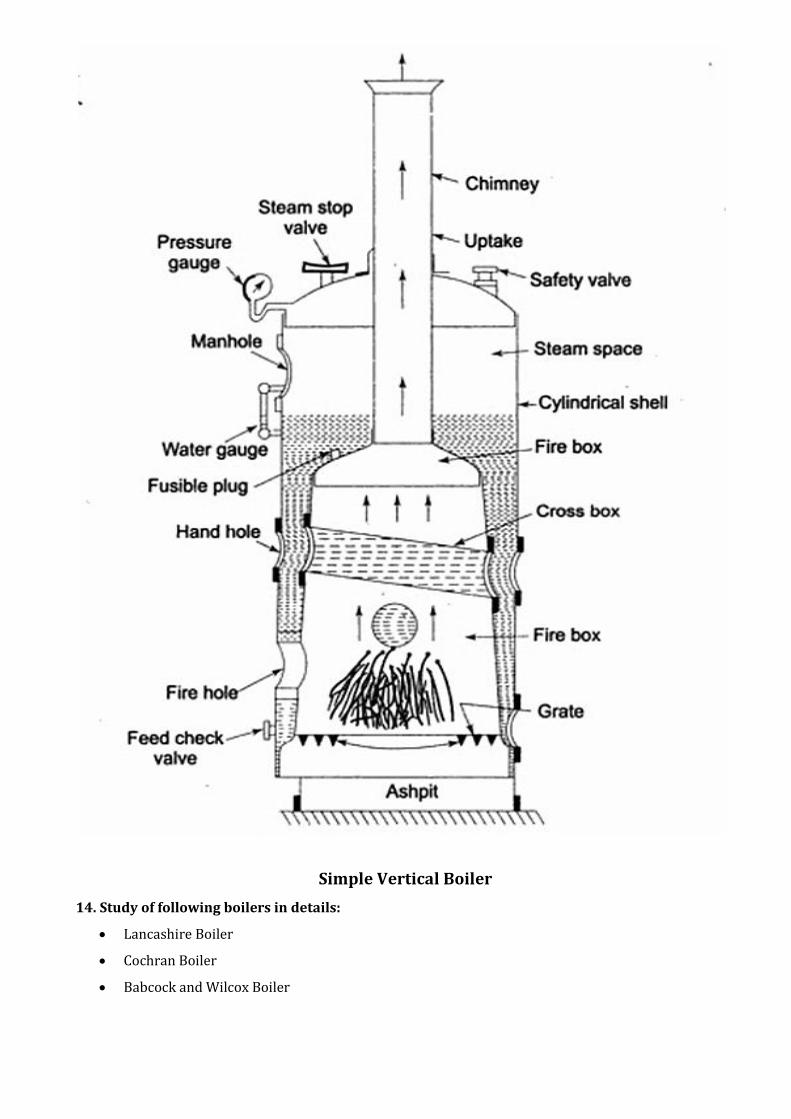
Simple Vertical Boiler
14. Study of following boilers in details:
Lancashire Boiler
Cochran Boiler
Babcock and Wilcox Boiler

Review Questions:
1. Define boiler. State its applications.
2. Explain classification of boiler with example in detail.
3. State the advantages of high-pressure boilers.
4. Explain the difference between the fire tube and water tube boiler. What are its merits and
demerits?
5. Explain function of below mentioned basic parts of boiler:
A. Anti-priming pipe
B. Furnace
C. Man hole
D. Mud box
6. Draw neat sketches and explain construction and working of following boilers in detail:
A. Lancashire boiler (orthographic views)
B. Cochran boiler
C. Babcock and Wilcox boiler

GOVERNMENT ENGINEERING COLLEGE, VALSAD
MECHANICAL ENGINEERING DEPARTMENT
PRACTICAL 2: STUDY OF BOILER MOUNTINGS AND ACCESSORIES
Objective:
1. Describe the construction of different mountings and accessories.
2. Understand the working of various mountings and accessories.
3. Effect of mountings and accessories on performance.
Theory:
Boiler Mountings:
All boilers are fitted with fittings or mountings for safety of the boilers and for complete control of
the process of steam generation. According to IBR the following mountings should be fitted to the boilers
1. Two Safety valves
2. Two water level indicators
3. Pressure gauge
4. Steam stop valve
5. Feed check valve
6. Blow off cock
7. Attachment of inspector’s test gauge
8. Man hole
9. Mud holes or sight holes
Boiler Accessories:
Most of the boilers are fitted with accessories. The major functions of boiler accessories are:
1. To increase the efficiency of the boiler plant.
2. To help in the smooth working of the boiler plant.
Commonly used boiler accessories are:
1. Feed pumps
2. Injector
3. Economiser
4. Air preheater
5. Superheater
6. Steam separator
7. Steam trap
8. Damper
Review Questions:
1. Define boiler mountings and boiler accessories.
2. Explain the function, location, construction and working of following mountings with neat sketch:
a. Safety valve
b. Water level indicator
c. Pressure gauge
d. Steam stop valve
e. Feed check valve
f. Blow off cock
g. Fusible plug
3. Explain the function, location, construction and working of following accessories with neat sketch:
a. Economiser
b. Super-heater
c. Air preheater
d. Damper

GOVERNMENT ENGINEERING COLLEGE, VALSAD MECHANICAL ENGINEERING DEPARTMENT
PRACTICAL 3: STUDY OF TWO AND FOUR STROKE PETROL AND DIESEL ENGINES
Objective:
1. Understand working of Petrol and Diesel engine.
2. Evaluate difference between 4 stroke and 2 stroke engine.
3. Construction difference of CI and SI engine.
Theory:
Introduction:
Any machine, which derives heat energy from the combustion of fuel and converts part of this
energy in to mechanical work, is known as heat engine. Heat engines are mainly divided in to: external
combustion and internal combustion engines.
Steam engine falls under the category of external combustion engine where as internal
combustion engine (popularly known as I C Engine) are those engines in which the combustion of the fuel
takes place inside the engine cylinder. These are commonly used in trucks and buses, scooters and cars,
ships and locomotive, agriculture and earth moving machinery, many industrial applications and for
power generation.
Classification:
The I C Engines may be classified as follows:
1. According to the types of fuel used
2. According to the number of strokes
3. According to the cycle of operation
4. According to the method of ignition
5. According to the method of cooling
6. According to the method of governing
7. According to the speed of the engine
8. According to the arrangement of cylinder
Engine parts and their functions:
Frame, Cylinder and Cylinder Head, Piston, Connecting rod, Crank, Crankshaft, Valve gear
mechanism
Working of Four-stroke Petrol and Diesel engines:
Suction stroke:
During this stroke, inlet valve opens and exhaust valve is closed, the pressure in the cylinder will
be atmosphere. As the piston moves from TDC to BDC, the volume in the cylinder increase and pressure
decrease. This creates a pressure difference between the atmosphere and inside the cylinder. Due to this
pressure difference the petrol and air mixture (charge) in case of petrol engine and only air will enter into
the cylinder.
Compression stroke:
During this stroke, both the inlet valve and exhaust valve are closed, the piston moves from BDC
to TDC. In this stroke the charge or (air in case of diesel engine) will be compressed, so pressure and
temperature will increase.
Expansion stroke:
During this stroke, both the inlet valve and exhaust valve are closed, the piston moves from TDC
to BDC. The high pressure and high temperature burnt gases force the piston to perform this stroke,
called power stroke. This stroke is also known as expansion or working stroke. The engine produces
mechanical work or power during this stroke.
Exhaust stroke:
During this stroke, the inlet valve is closed and exhaust valve opens. The piston moves from BDC
to TDC and during this motion of the piston pushes the exhaust gases out of the cylinder at constant
pressure.
Working of Two-Stroke I.C. Engine:
In two-stroke engine, the cycle is completed in two stroke, i.e. all the four operations are completed
in two stroke of the piston or one revolution of the crankshaft. In two-stroke engine, ports (holes) replace
the valves. The movement of the piston controls the opening and closing of port. The exhaust gases are
removed from the cylinder with the help of fresh compressed charge and it is called scavenging. A specific
crown shape is given to the piston, which helps to prevent the loss of incoming charge and helps for
exhausting the hot gases effectively.
In case of single cylinder engines as used in scooter and motorcycle, three ports are provided as
exhaust, transfer and inlet. Through the exhaust port, the hot gases are pushed out. Through the transfer
port, the fresh charge from the bottom of the engine piston/crankcase is supplied to the cylinder and also
helps for exhaust. Through the inlet port, fresh charge from the carburetor is taken in to the cylinder
crankcase.

Review Questions:
1. List various elements (components) of I.C Engines. Explain the function of each component.
2. Differentiate I.C. engine and E.C. engine by giving examples.
3. Draw working sketch (with p-v diagram) of four stroke gasoline (petrol) and diesel engine. Explain
any one of them.
4. Draw working sketch of 2-stroke gasoline (petrol) and diesel engine. Explain any one.
5. Differentiate between S.I. and C.I engine.
6. Differentiate between 2-stroke and 4-stroke I.C engine.
7. Give reason for the following.
(a) Fins are provided on the surface of the cylinder.
(b) Piston is provided with 3 different rings.
(c) Flywheel of four-stroke engine is heavier than that of two-stroke engine.
(d) Mechanical efficiency of 2-stroke engine is higher than the 4-stroke engine?
(e) Why diesel engines are called C.I engines?
8. State the function of crankcase and deflector (piston crown) in two strokes I.C. engines

GOVERNMENT ENGINEERING COLLEGE, VALSAD MECHANICAL ENGINEERING DEPARTMENT
PRACTICAL 4: DETERMINE BRAKE THERMAL EFFICIENCY OF AN I. C. ENGINE
Objective:
1. To understand performance parameters
2. To differentiate between Brake thermal and indicated thermal efficiency
3. To determine Brake thermal efficiency
4. To determine Indicated power, Brake power, Friction power.
Apparatus: (1) Stop watch, (2) Tachometer, (3) Measuring glass tube Set up Diagram:
4 Stroke 2 cylinderDiesel Engine
HydraulicDynamometer W
Fuel Air
Water Inlet
Water
Water
Water OutWater Out
Shaft
Specifications: - Sp. Gravity of diesel = 0.85 - Calorific value of diesel = 42000 kJ / kg.
Observations: - Bore = ________ mm. - Stroke = ________ mm. - No. of cylinders = ______ - _______ cooled engine - _______ stroke ________ Engine - Linear distance between Dynamometer Drum and point of load applied L1 = ______ m.
Observation Table: Sr. No. Dynamometer reading
‘ W ’ (Kg) Time taken to consume 10 ml.
‘ T ‘ (Sec) Crank shaft speed
N (RPM)
1
2
3

Sample Calculation:
(1) Fuel consumption rate Tfm 10 10-3 Sp. Gravity
= ________ Kg/sec
(2) Heat Energy supplied by fuel Qs = mf x C.V = ________ kJ/sec
(3) Brake Power 60000
2 NTBP
; where T = Wx9.81 X L1 = __________ N-m
= _________ kW
(4) Brake specific fuel consumption bsfcBP
m f x 3600
= _________ Kg/kW-hr (5) Brake mean effective pressure
BMEP = LAnx
BP 60000 where n= no. of power strokes/min and x =no of cylinders
= __________ Pa = _________ Bar (6) Brake thermal efficiency:
fuelbyEnergy
Brakepowerbth
.sup
= 100sQ
BP = ____________ %
Computation Table:
Sr. No.
Fuel consumption Rate
‘mf ‘ (Kg/sec)
Brake power BP (kW)
Brake specific fuel consumption
‘BSFC‘ (Kg / kWHr)
Brake mean effective pressure
‘BMEP‘(bar)
Thermal efficiency ‘ηbth ‘ (%)
1
2
3
Conclusion:

Review Questions:
1) Explain the following terms related to I.C. engines:
2) A four cylinder two stroke petrol engine with stroke to bore ratio 1.2 develops 32 kW brake power
at 2500 rpm. The mean effective pressure in each cylinder is 9 bar and mechanical efficiency is
86%. Determine (1) Diameter and stroke of each cylinder, (2) Brake thermal efficiency, (3)
Indicated thermal efficiency, (4) Brake specific fuel consumption in kg/kwhr. Take Petrol
consumption = 9 kg/hr and Calorific value of petrol = 43 MJ/kg.
3) A six cylinder 4 stroke I.C. engine is to produce 95 kW brake power at 800 rpm. The stroke to bore
ratio is 1.25, mean effective pressure is 7 bar. Determine the bore and stroke of the engine. Assume
mechanical efficiency as 80%.
a. Swept volume b. Compression ratio
c. Indicated power d. Brake power
e. Friction power f. Specific fuel consumption
g. Mechanical efficiency h. Thermal efficiency
i. Air standard efficiency j. Relative efficiency
k. Specific fuel consumption l. Specific output

GOVERNMENT ENGINEERING COLLEGE, VALSAD MECHANICAL ENGINEERING DEPARTMENT
PRACTICAL 5: STUDY OF DIFFERENT TYPES OF AIR COMPRESSORS
Objective:
1. Understand the working of air compressor
2. Know the constructional details of important parts of air compressor
3. Know the classification and application of compressor
Theory:
Definition:
An air compressor is a device that converts power (using an electric motor, diesel or gasoline engine, etc.)
into potential energy stored in pressurized air (i.e., compressed air).
Classification of compressor:
Application of compressor:
Blowing up balloons or inflatable products.
Adding air to tires on bikes and on vehicles.
Using various pneumatic tools for home projects.
Painting vehicles in an auto body shop.
Sandblasting in a machine shop and manufacturing facilities.
Operating pneumatic material handling equipment.
Finishing and packaging with pneumatic devices.
Review Questions:
1. Write the classification of Air compressor. Write the uses of compressed air.
2. Draw the neat sketches of compressor with P – V diagram with and without clearance.
3. What are the advantages of multistage compression?
4. Define the following terms: Compression ratio, compressor capacity, and volumetric efficiency, free
air delivery (FAD).
5. Classify rotary air compressors. Explain construction and working of centrifugal compressor
with neat sketches.
6. Explain with neat sketch construction and working of axial flow air compressor.
7. Differentiate between reciprocating compressor & centrifugal compressor with respect to principle
of working.
GOVERNMENT ENGINEERING COLLEGE, VALSAD
MECHANICAL ENGINEERING DEPARTMENT
PRACTICAL 6: STUDY OF REFRIGERATION AND AIR CONDITIONING
Objective:
1. List out different applications of refrigeration and air conditioning.
2. Understand the construction and working of
(a) Simple vapour compression Refrigeration system.
(b) Simple vapour absorption Refrigeration system.
(c) Window Air conditioner.
Theory:
Refrigeration is the process of cooling or reducing and maintaining the temperature of an
enclosed space below surrounding temperature. In order to maintain the low temperature of the
refrigerated space, it is necessary to remove heat continuously equal to the amount of heat leaking into
the system, rejecting the same to the surrounding atmosphere at higher temperature. The machine that
produces cold is known as “refrigerator.”. Theoretically, refrigerator is a reversed heat engine, or a heat
pump which pumps heat from a cold body and deliveries it to a hot body with the help of external work.
The working fluid used in refrigerator is known as refrigerant. It is mainly classified as Inorganic,
hydrocarbon (HC), hydro-fluorocarbons (HFC), hydro-chloro-fluorocarbon (HCFC), chloro-fluorocarbons
(CFC) and azeotrope. The commonly used refrigerants are Ammonia R-717(NH3), R-12 (CCl2F2), R-22
(CHClF2), R134a (C2H2F4) and R404A (R125/143a/134a {44/52/4}) and R410A (R32/125 {50/50})
1. Vapour compression refrigeration system
E.g. Domestic Refrigerator
2. Simple vapour absorption system
E.g. Electrolux, Aqua-Ammonia System for large cold storages
3. Window air conditioner
The basic function of window air conditioner is to control the temperature, humidity, air purity and air
cleaning. It is most suitable for office rooms, bedrooms in homes and smaller areas. These air
conditioners are designed and constructed for continuous use and provided with the arrangements of
drawing fresh air and throwing the exhaust air.

Review Questions:
1. Define the following terms: Air conditioning, Refrigeration, Coefficient of performance
2. What is refrigeration? What is refrigerating effect? What is one ton of refrigeration?
3. Give the classification of air conditioning systems.
4. What is refrigerant? What are the desirable properties of refrigerant?
5. With a line sketch describe simple vapour compression system. (Draw p-h and T-S chart)
6. With a line sketch, describe the vapour absorption refrigeration system.
7. Explain, working and construction of window air-conditioner in detail using neat sketch.
8. What is split air conditioner? How it differs from window air conditioner?
9. Why air conditioning is required in aircraft? Why air is used as a refrigerant?
10. Explain bell - Coleman air refrigeration cycle.
11. a) In S.I. unit one ton of refrigeration is equivalent to,
(i) 1.5 KW (ii) 2.5 KW (iii) 3.517 KW (iv) 5 KW
b) Coefficient of performance is always
(i) More than unity (ii) less than unity (iii) equal to unity (iv) none
c) In mechanical refrigeration system, the refrigerant has the maximum temperature
(i) In evaporator (ii) between condenser and evaporator
(iii) Before expansion valve (IV) between compressor & condenser
d) In vapour compression system, the condition of the refrigerant before entering the expansion or
throttle valve is,
(i) High pressure saturated liquid (ii) wet vapour
(iii) Very wet vapour (IV) none.
e) Air condition includes,
(i) Cooling (ii) heating (iii) removal of impurities (iv) all of the above.

GOVERNMENT ENGINEERING COLLEGE, VALSAD MECHANICAL ENGINEERING DEPARTMENT
PRACTICAL 7: STUDY OF DIFFERENT TYPES CLUTCHES COUPLING AND BRAKES
Objective:
1. State the working of different types of Couplings clutches and brakes
2. Know the construction and operation of different types of couplings, clutches and brakes
3. Application of couplings clutches and brakes.
Theory:
Coupling:
Couplings are used for joining sections of long transmission shafts. They are also used for connecting the
shaft of a driving machine to the shaft of a separately built machine so as to give an effect of continuous
shaft.
The general classification of couplings is given as under:
COUPLINGS
Rigid Coupling Flexible coupling
Sleeve or Box or Split muff or Flange coupling
Muff Coupling clamp coupling
Bushed pin type Universal Old ham
Flange coupling coupling coupling
1. Rigid coupling
Rigid couplings are used to connect two shafts when they are in perfect axial alignment.
(a) Sleeve or Box or Muff coupling:
(b) Split muff or clamp coupling:
(c) Flange couplings:

2. Flexible coupling
These types of couplings are used to protect the driving and driven machines from effect of shocks
excesses stresses due to deflection and vibrations, which may arise from misalignment of shafts.
(a) Bush pin type flange coupling:
(b) Oldham coupling:
(c) Universal coupling:
Clutch:
The flow of mechanical power is controlled by means of a clutch. The clutch is a mechanical device, which
is used to connect or disconnect the source of power from the remaining parts of the power transmission
systems at the will of the operator. An automotive clutch can permit the engine to run without driving the
car. This is desirable when the engine is to be started or stopped or when the gears are to be shifted.
1. Single plate friction clutch
2. Multi disc clutch
3. Cone clutch
4. Centrifugal clutch
Brake:
A brake is a mechanical device by means of which artificial resistance is applied to a moving system or
machine in order to slow down or completely stop the motion of a machine. In performing this function,
the brake absorbs either kinetic energy of moving members such as rotating drum, machine, automobile
vehicle or potential energy given up by objects being lowered by hoists, elevators.
The energy absorbed by a brake is converted into heat energy and dissipated in the surroundings air.
There are two distinct functions of vehicle brakes.
To stop or slow down the vehicle in the shortest possible distance in emergencies.
To control the vehicle to be retained when descending a hill.
Types of brakes:
According to the means used for transforming the energy by the braking elements, the brakes are
classified as
(i) Hydraulic brake
(ii) Electric brake
(iii) Mechanical brake.
Depending upon the shape of the friction material the mechanical brakes are classified as block brake,
internal or external shoe brakes and band brakes.
1. Block brake
2. Internal expanding brake
3. Band brake

Materials for Brake Lining:
The materials used for brake lining should have,
(i) High co-efficient of friction with minimum fading
(ii) Low wear rate
(iii) High heat resistance
(iv) High heat dissipation capacity
(v) Adequate mechanical strength and
(vi) Should not be affected by moisture and oil. The materials commonly used are wood, leather and
asbestos.
Difference between a brake and a clutch:
1. A brake is used to reduce the rotational motion or to stop it, where as a clutch is used to transmit
the motion and power of a moving body to another body.
2. In brakes the applications of force results into frictional resistance whereas in clutches application
of force results into frictional force between clutch plates which helps them to transmit motion and
power.
3. During normal working conditions a brake always remains disengaged where as a clutch always
remains engaged.
4. When a brake is applied the energy of the moving member is lost in friction but in a clutch no such
loss occurs.
Review Questions:
1. What is the function of clutch in automobile vehicle? What are various types of clutches? Name only
which type of clutch is used in scooter and car.
2. What is the function of coupling? Name only various types of couplings. Explain Oldham coupling.
3. Differentiate between clutch and coupling. Describe Disk clutch.
4. What is function of brakes? How they are classified? Explain with a neat diagram working of
internal expanding shoe brake.
5. What is the essential difference between coupling and clutch?
6. With a neat sketch describe the centrifugal clutch.
7. Explain band and shoe brake.
GOVERNMENT ENGINEERING COLLEGE, VALSAD MECHANICAL ENGINEERING DEPARTMENT
PRACTICAL 8: STUDY OF POWER TRANSMISSION DRIVES
Learning Objectives:
1. Know different power and motion transmission elements
2. Understand the different types of belts and ropes used in practice along with their material.
3. Understand the working of chain drive along with their advantages and disadvantages.
4. Know the different types of gear trains.
Theory:
Belt and Rope Drives:
To transmit the power from one shaft to another, pulleys are mounted on the two shafts. The pulleys are
then connected by an endless belt or rope passing over the pulleys. The connecting belt or rope is kept in
tension so that motion of one pulley is transferred to the other without slip. Varying the diameter of the
pulleys can vary the speed of the driven shaft.
Types of belt : Flat belt, V-belt, Circular belt or Rope
Type of flat belt drives : Open belt drive, Crossed or twisted belt drive
Chain drives:
To avoid slippage, steel chains are used. The chain is made up of a rigid links, which are hinged together
in order to provide the necessary flexibility for wrapping around the driving and driven wheels. The
wheels have projecting teeth and fit into the corresponding recesses, in the links of the chain.
The wheel and the chain are thus constrained to move together without slipping and ensure
perfect velocity ratio. The toothed wheels are known as sprocket wheels or simply sprockets. These
wheels resemble to spur gears.
Gear Trains:
A gear train is a combination of gears used to transmit motion and power from one shaft to another. It
becomes necessary when it is required to obtain large speed reduction with in a small space. The
following are main types of gear trains.
Simple gear train:
A pair of mating external gears always moves in opposite direction. All odd numbered gears move in one
direction and all even numbered gears move in opposite direction. Speed ratio is the ratio of the speed of
the driving to the driven shaft, is negative when the input and output gears rotate in opposite direction
and it is positive when the two rotate in same direction. Reciprocal of speed ratio is known as the train
valve of the gear train. All the gears can be in a straight line or arranged in zigzag manner.

Compound gear train:
When a series of gears are connected in such a way that two or more gears rotate about an axis with the
same angular velocity, it is known as compound gear train. In this type, some of the intermediate shafts,
i.e. other than the input and output shaft s, carry more than one gear.
Advantages of gear train:
1. It transmits exact velocity ratio.
2. It may be used to transmit large power.
3. It has high efficiency.
4. It has compact layout.
Disadvantages of Gear train:
1. The manufacture of gears requires special tools and equipment.
2. The error in cutting teeth may cause vibrations and noise during operation.
Review Questions:
1. List various power transmission elements with their applications.
2. What are bearings? How they are classified? Explain Thrust Bearing.
3. Write short note on helical gear, spiral gear and bevel gear. (Draw Sketch)
4. What is V- belt drive? How it differs from a flat belt drive. List the various belt drives and explain
cross belt drive.
5. Differentiate individual drive and group drive.
6. Compare Belt drive, Chain drive and Gear drive.
7. What is creep in belt drives? Explain.
8. Define velocity ratio of gears drive.
9. Explain the following terms with respect to gear
a) Module b) Circular pitch c) pitch diameter d) Addendum
Examples:
1. Two parallel shafts are 6 m apart. The diameters of the driving and driven pulleys are 600 mm and
500 mm respectively. Find the length of the belt when the pulleys are connected by a) open belt and
b) cross belt.
2. A gear wheel A having 24 teeth drives another gear wheel B having 30 teeth. Gear B rotates at 250
rpm. Find the speed of driving wheel A and velocity ratio.