Embed Size (px)
Citation preview
User Manual
Gemtek WiMAX Modem
WIXS-177

i
CONTENTS
Chapter 1 Overview..................................................................1-1
1.1. Indoor CPE............................................................................................. 1-1
1.2. Outdoor CPE.......................................................................................... 1-2
Chapter 2 WEB-GUI.................................................................2-3
2.1. System Configuration Login.................................................................. 2-3
2.2. System Logout ....................................................................................... 2-6
2.3. Account .................................................................................................. 2-7
2.4. Date ........................................................................................................ 2-8
2.5. Language................................................................................................ 2-9
2.6. Scanner................................................................................................. 2-10
2.7. Authentication...................................................................................... 2-12
2.8. Bridge Mode ........................................................................................ 2-14
2.9. NAT Mode ........................................................................................... 2-15
2.10. Firewall ................................................................................................ 2-16
2.11. DHCP Server........................................................................................ 2-18
2.12. NAT ALG............................................................................................. 2-20
2.13. Port Forwarding ................................................................................... 2-21
2.14. Port Trigger .......................................................................................... 2-22
2.15. DDNS................................................................................................... 2-23
2.16. TR-069 ................................................................................................. 2-25
2.17. SNMP................................................................................................... 2-27
2.18. Log ....................................................................................................... 2-28
2.19. Upgrade................................................................................................ 2-29
2.20. Recovery .............................................................................................. 2-31
2.21. Reboot .................................................................................................. 2-32
ii
FIGURES
Figure 1-1 Indoor CPE Front Panel LED ............................................... 1-1
Figure 1-2 Outdoor CPE installation ...................................................... 1-2
Figure 2-1 Login Page ............................................................................ 2-3
Figure 2-2 WiMAX Status...................................................................... 2-4
Figure 2-3 WiMAX Status-Service Flow ............................................... 2-4
Figure 2-4 Network Status ...................................................................... 2-5
Figure 2-5 Device Status......................................................................... 2-5
Figure 2-6 Logout ................................................................................... 2-6
Figure 2-7 Account ................................................................................. 2-7
Figure 2-8 Date ....................................................................................... 2-8
Figure 2-9 Language............................................................................... 2-9
Figure 2-10 Scanner with Bandwidth range 6~10MHz........................ 2-10
Figure 2-11 Scanner with Bandwidth range 3~5MHz ...........................2-11
Figure 2-12 Authentication................................................................... 2-12
Figure 2-13 Authentication-View Certificates...................................... 2-13
Figure 2-14 Bridge Mode...................................................................... 2-14
Figure 2-15 NAT Mode......................................................................... 2-15
Figure 2-16 Firewall ............................................................................. 2-16
Figure 2-17 Firewall Filter.................................................................... 2-17
Figure 2-18 DHCP Server Enabled....................................................... 2-18
Figure 2-19 DHCP Server Disabled...................................................... 2-19
Figure 2-20 NAT ALG.......................................................................... 2-20
Figure 2-21 Port Forwarding ................................................................ 2-21
Figure 2-22 Port Trigger ....................................................................... 2-22
Figure 2-23 DDNS Enabled.................................................................. 2-23
Figure 2-24 DDNS Disabled................................................................. 2-24
Figure 2-25 TR-069 .............................................................................. 2-26
Figure 2-26 TR-069-Certificate File Upload ........................................ 2-26
Figure 2-27 SNMP enabled................................................................... 2-27
Figure 2-28 SNMP disabled.................................................................. 2-27
Figure 2-29 Log .................................................................................... 2-28
Figure 2-30 Web/FTP Upgrade............................................................. 2-29
Figure 2-31 Web Upgrade Summary .................................................... 2-30
Figure 2-32 TFTP Upgrade................................................................... 2-30
Figure 2-33 Recovery ........................................................................... 2-31

iii
Figure 2-34 Reboot Button ................................................................... 2-32
Figure 2-35 Reboot Confirmation......................................................... 2-33

1-1
Chapter 1 Overview
This chapter describes the panel function and installation procedure for the
CPE.
1.1. Indoor CPE
Front Panel LED
Power LED: ON: power on OFF: power fail
LAN LED: ON: connect OFF: disconnect Blinking: data transmit
When the CPE powers on, the LED indicates the CPE states as follow.
Only Red LED is Blinking: synchronization
Only Yellow LED is Blinking: authentication
Only Green LED is Blinking: DHCP client negotiation
After the CPE has connected to the base station, the signal strength LED are
defined as follow.
Only Red LED is ON: the signal is weak. (CINR<8dB)
Yellow LED is ON: the signal strength is medium. (8dB≤CINR<15dB)
Green LED is ON: the signal strength is good. (15dB≤CINR)
Figure 1-1 Indoor CPE Front Panel LED

1-2
Rear Panel
Power jack: DC 12V / 1.5A
LAN port: 10/100Base-TX
Reset button: To reboot the CPE
1.2. Outdoor CPE
Power Injector – Power Over Ethernet 802.3af compliant
LAN port: 10/100Base-TX
Figure 1-2 Outdoor CPE installation
2-3
Chapter 2 WEB-GUI
This chapter describes how to configure the CPE in order to connect to the base
station.
2.1. System Configuration Login
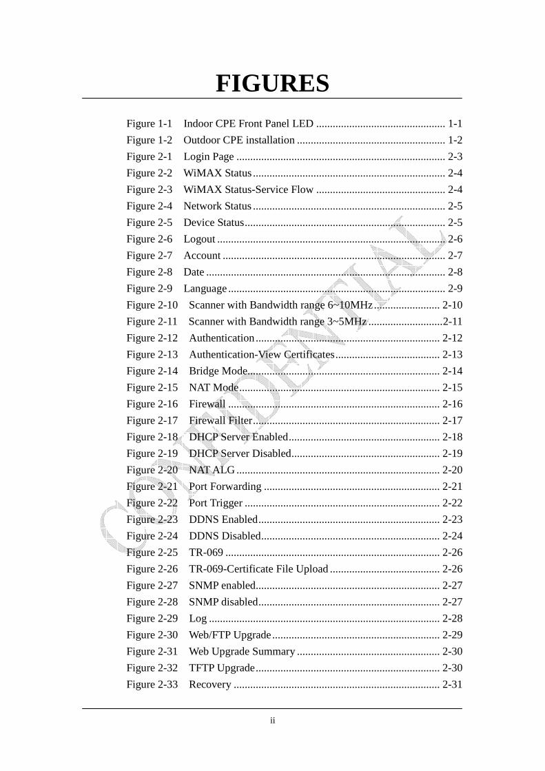
The CPE will enable a DHCP server by default. Computers or network devices
connected to its LAN side can get IP address automatically from CPE. If you disable
CPE’s DHCP server by yourself, set the IP address, netmask, and gateway as
following.
IP address: 10.1.1.x, 1 ≤ x ≤ 253
Netmask: 255.255.255.0
Gateway: 10.1.1.254
Connect to http://10.1.1.254/ with a browser, and you will see a webpage such as the
one shown in Figure 2-1. The administrator username and password are as shown
below:
Username: admin
Password: admin
Gemtek CPE also support multi-level user login. Please contact with Gemtek to
define multi-user features.
Figure 2-1 Login Page
2-4
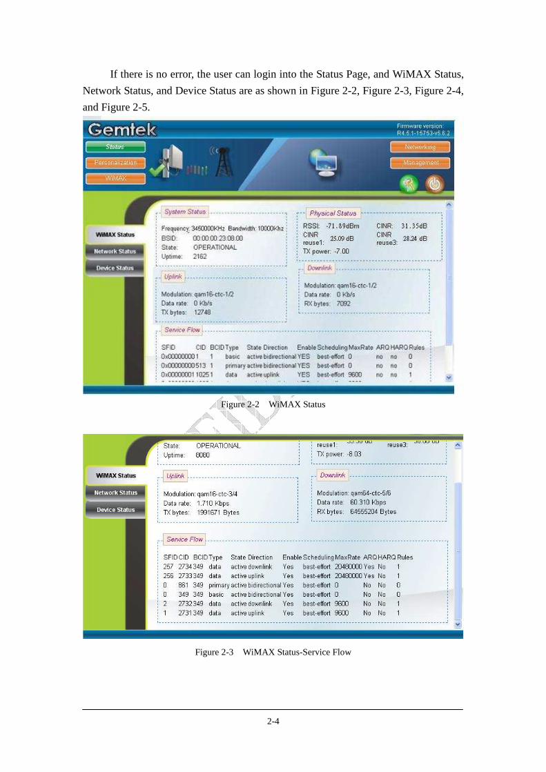
If there is no error, the user can login into the Status Page, and WiMAX Status,
Network Status, and Device Status are as shown in Figure 2-2, Figure 2-3, Figure 2-4,
and Figure 2-5.
Figure 2-2 WiMAX Status
Figure 2-3 WiMAX Status-Service Flow
2-5
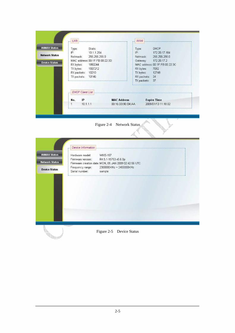
Figure 2-4 Network Status
Figure 2-5 Device Status
2-6
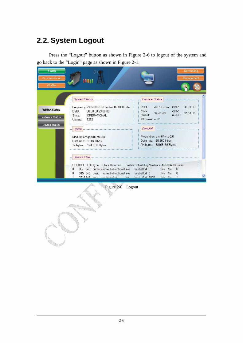
2.2. System Logout
Press the “Logout” button as shown in Figure 2-6 to logout of the system and
go back to the “Login” page as shown in Figure 2-1.
Figure 2-6 Logout
2-7
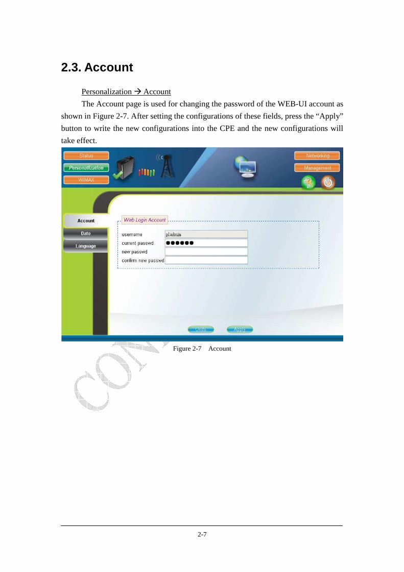
2.3. Account
Personalization � Account
The Account page is used for changing the password of the WEB-UI account as
shown in Figure 2-7. After setting the configurations of these fields, press the “Apply”
button to write the new configurations into the CPE and the new configurations will
take effect.
Figure 2-7 Account
2-8
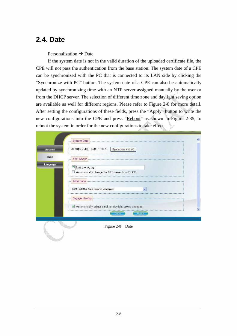
2.4. Date
Personalization � Date
If the system date is not in the valid duration of the uploaded certificate file, the
CPE will not pass the authentication from the base station. The system date of a CPE
can be synchronized with the PC that is connected to its LAN side by clicking the
“Synchronize with PC” button. The system date of a CPE can also be automatically
updated by synchronizing time with an NTP server assigned manually by the user or
from the DHCP server. The selection of different time zone and daylight saving option
are available as well for different regions. Please refer to Figure 2-8 for more detail.
After setting the configurations of these fields, press the “Apply” button to write the
new configurations into the CPE and press “Reboot” as shown in Figure 2-35, to
reboot the system in order for the new configurations to take effect.
Figure 2-8 Date

2-9
2.5. Language
Personalization � Language
The Language page allows users to select one of the languages in the
drop-down list for viewing the WEB-GUI as shown in Figure 2-9. After selecting the
desired language, press the “Apply” button to view the WEB-GUI in the selected
language.
Figure 2-9 Language
2-10
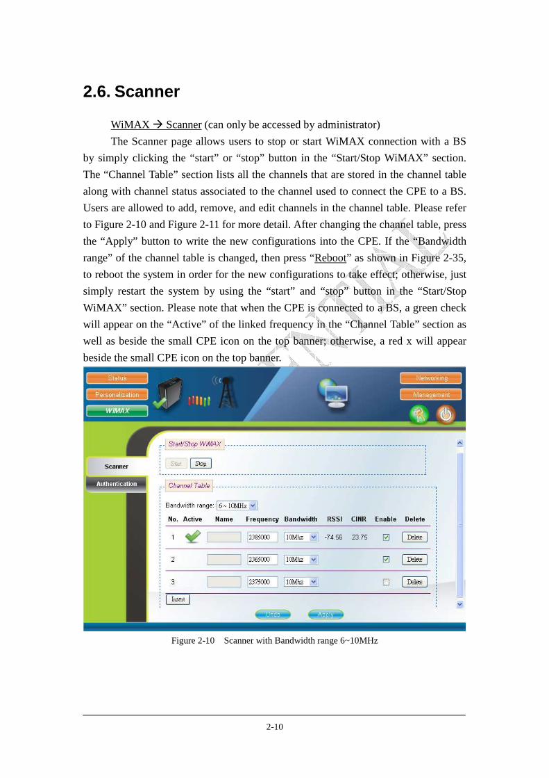
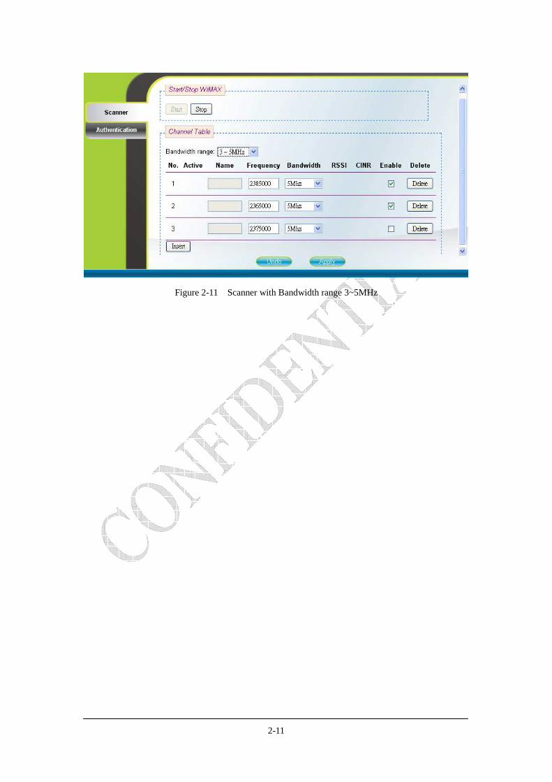
2.6. Scanner
WiMAX � Scanner (can only be accessed by administrator)
The Scanner page allows users to stop or start WiMAX connection with a BS
by simply clicking the “start” or “stop” button in the “Start/Stop WiMAX” section.
The “Channel Table” section lists all the channels that are stored in the channel table
along with channel status associated to the channel used to connect the CPE to a BS.
Users are allowed to add, remove, and edit channels in the channel table. Please refer
to Figure 2-10 and Figure 2-11 for more detail. After changing the channel table, press
the “Apply” button to write the new configurations into the CPE. If the “Bandwidth
range” of the channel table is changed, then press “Reboot” as shown in Figure 2-35,
to reboot the system in order for the new configurations to take effect; otherwise, just
simply restart the system by using the “start” and “stop” button in the “Start/Stop
WiMAX” section. Please note that when the CPE is connected to a BS, a green check
will appear on the “Active” of the linked frequency in the “Channel Table” section as
well as beside the small CPE icon on the top banner; otherwise, a red x will appear
beside the small CPE icon on the top banner.
Figure 2-10 Scanner with Bandwidth range 6~10MHz
2-11
Figure 2-11 Scanner with Bandwidth range 3~5MHz
2-12
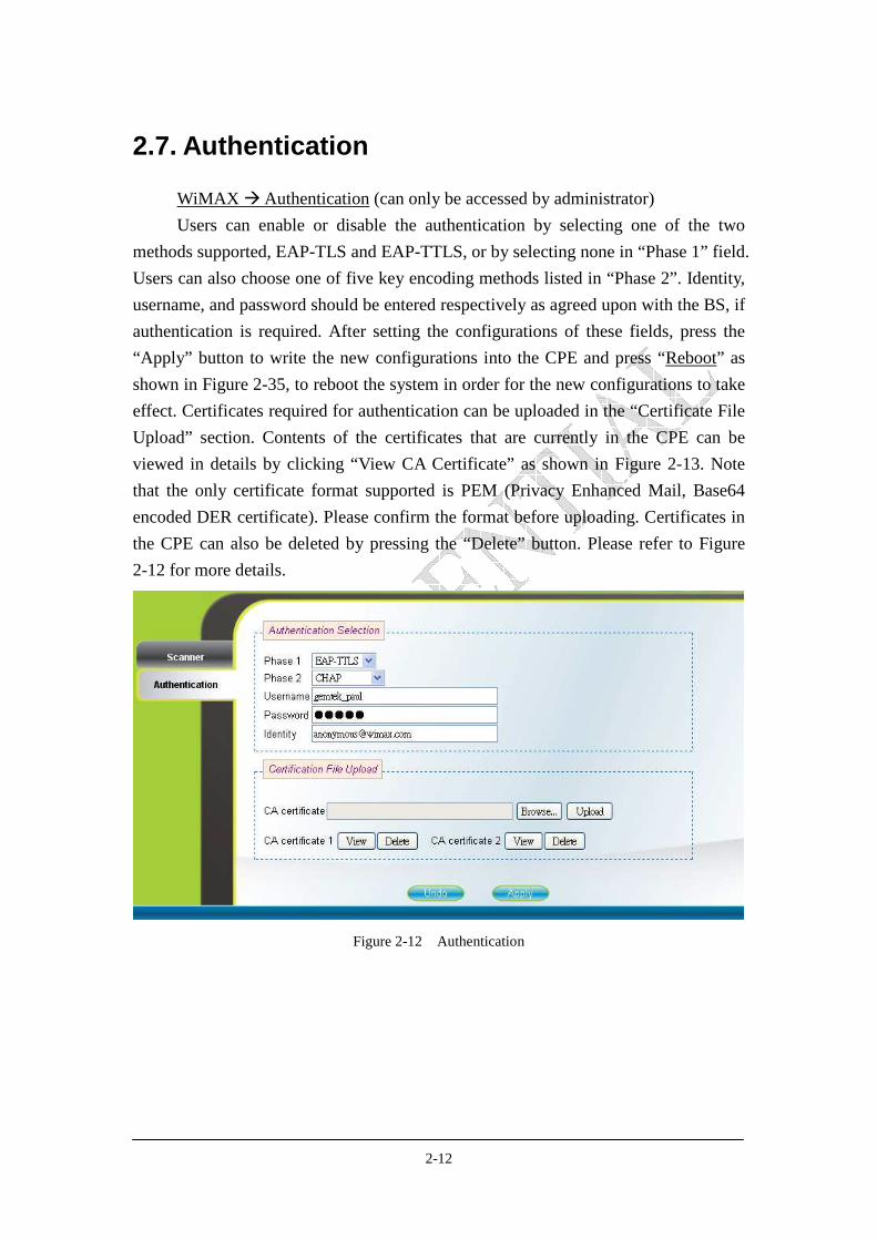
2.7. Authentication
WiMAX � Authentication (can only be accessed by administrator)
Users can enable or disable the authentication by selecting one of the two
methods supported, EAP-TLS and EAP-TTLS, or by selecting none in “Phase 1” field.
Users can also choose one of five key encoding methods listed in “Phase 2”. Identity,
username, and password should be entered respectively as agreed upon with the BS, if
authentication is required. After setting the configurations of these fields, press the
“Apply” button to write the new configurations into the CPE and press “Reboot” as
shown in Figure 2-35, to reboot the system in order for the new configurations to take
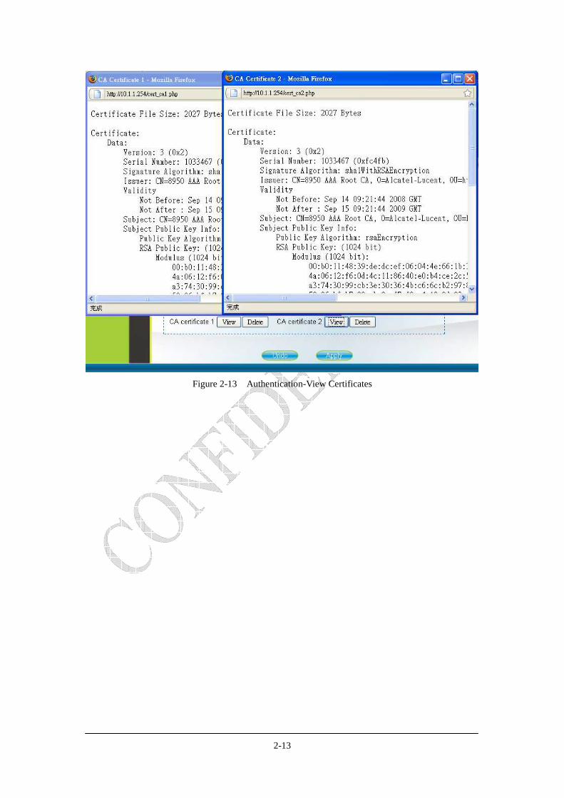
effect. Certificates required for authentication can be uploaded in the “Certificate File
Upload” section. Contents of the certificates that are currently in the CPE can be
viewed in details by clicking “View CA Certificate” as shown in Figure 2-13. Note
that the only certificate format supported is PEM (Privacy Enhanced Mail, Base64
encoded DER certificate). Please confirm the format before uploading. Certificates in
the CPE can also be deleted by pressing the “Delete” button. Please refer to Figure
2-12 for more details.
Figure 2-12 Authentication
2-13
Figure 2-13 Authentication-View Certificates
2-14
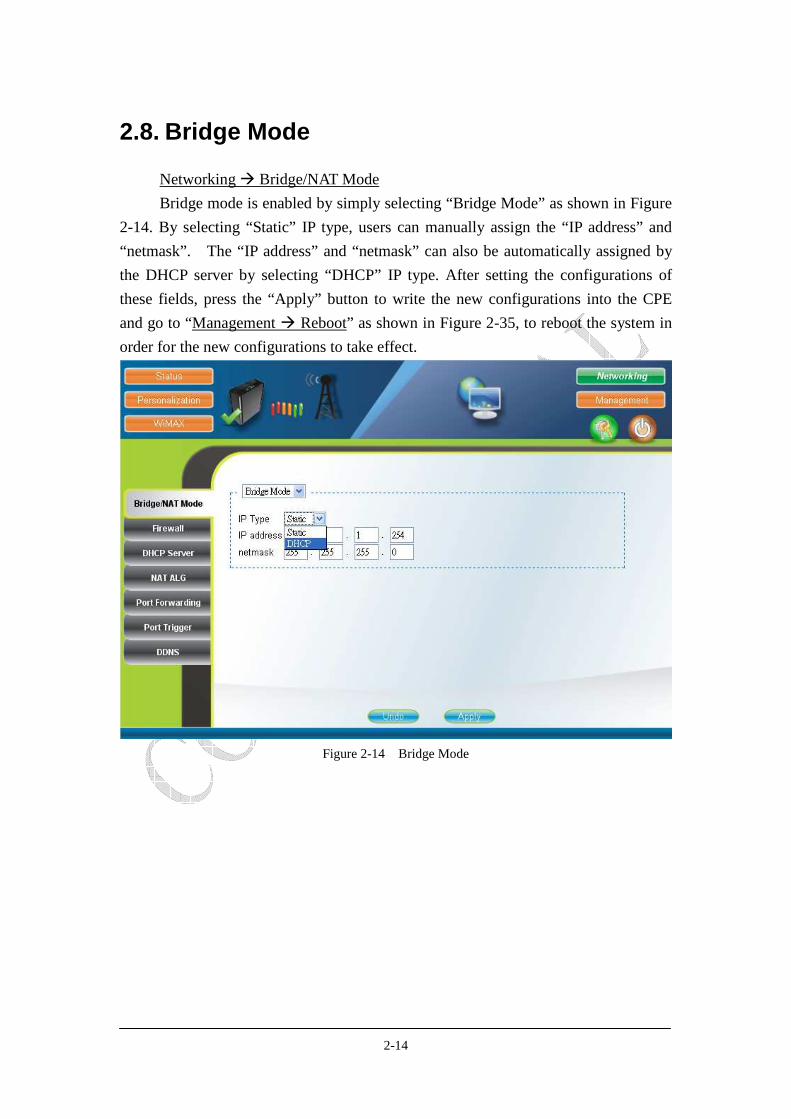
2.8. Bridge Mode
Networking � Bridge/NAT Mode
Bridge mode is enabled by simply selecting “Bridge Mode” as shown in Figure
2-14. By selecting “Static” IP type, users can manually assign the “IP address” and
“netmask”. The “IP address” and “netmask” can also be automatically assigned by
the DHCP server by selecting “DHCP” IP type. After setting the configurations of
these fields, press the “Apply” button to write the new configurations into the CPE
and go to “Management � Reboot” as shown in Figure 2-35, to reboot the system in
order for the new configurations to take effect.
Figure 2-14 Bridge Mode
2-15
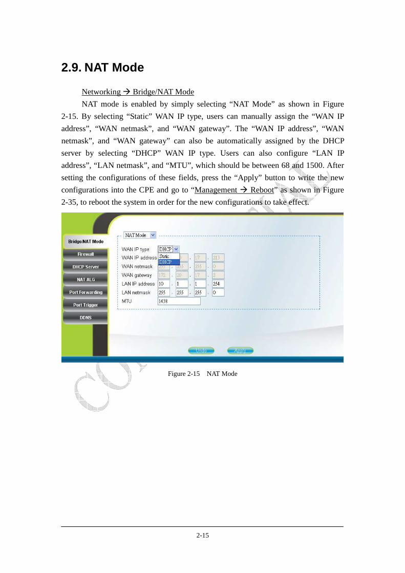
2.9. NAT Mode
Networking � Bridge/NAT Mode
NAT mode is enabled by simply selecting “NAT Mode” as shown in Figure
2-15. By selecting “Static” WAN IP type, users can manually assign the “WAN IP
address”, “WAN netmask”, and “WAN gateway”. The “WAN IP address”, “WAN
netmask”, and “WAN gateway” can also be automatically assigned by the DHCP
server by selecting “DHCP” WAN IP type. Users can also configure “LAN IP
address”, “LAN netmask”, and “MTU”, which should be between 68 and 1500. After
setting the configurations of these fields, press the “Apply” button to write the new
configurations into the CPE and go to “Management � Reboot” as shown in Figure
2-35, to reboot the system in order for the new configurations to take effect.
Figure 2-15 NAT Mode
2-16
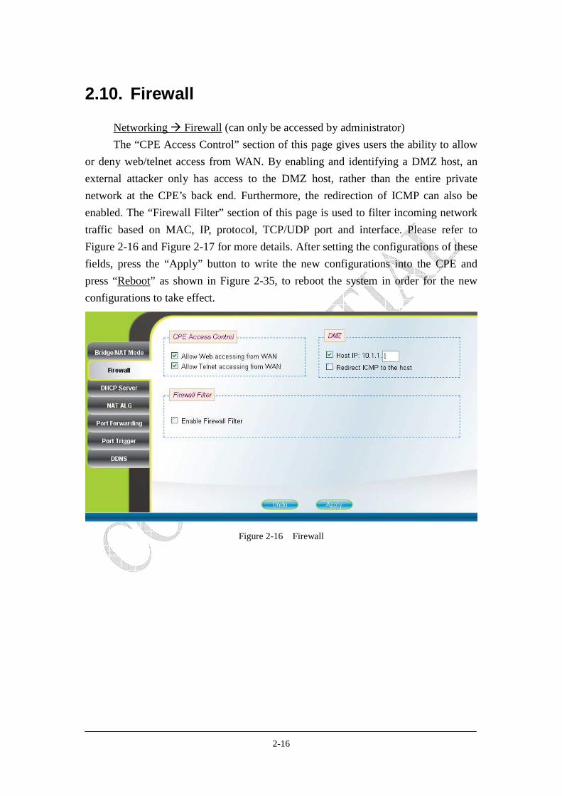
2.10. Firewall
Networking � Firewall (can only be accessed by administrator)
The “CPE Access Control” section of this page gives users the ability to allow
or deny web/telnet access from WAN. By enabling and identifying a DMZ host, an
external attacker only has access to the DMZ host, rather than the entire private
network at the CPE’s back end. Furthermore, the redirection of ICMP can also be
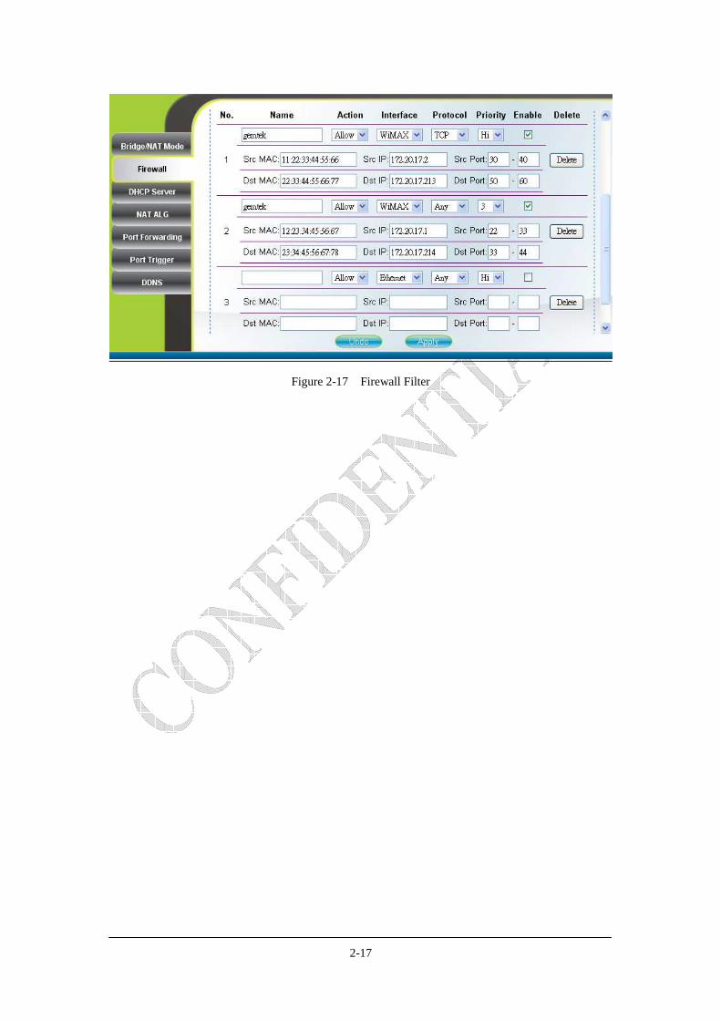
enabled. The “Firewall Filter” section of this page is used to filter incoming network
traffic based on MAC, IP, protocol, TCP/UDP port and interface. Please refer to
Figure 2-16 and Figure 2-17 for more details. After setting the configurations of these
fields, press the “Apply” button to write the new configurations into the CPE and
press “Reboot” as shown in Figure 2-35, to reboot the system in order for the new
configurations to take effect.
Figure 2-16 Firewall
2-17
Figure 2-17 Firewall Filter
2-18
2.11. DHCP Server
Networking � DHCP Server
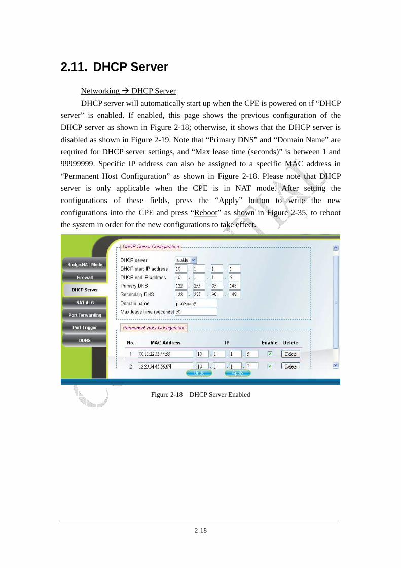
DHCP server will automatically start up when the CPE is powered on if “DHCP
server” is enabled. If enabled, this page shows the previous configuration of the
DHCP server as shown in Figure 2-18; otherwise, it shows that the DHCP server is
disabled as shown in Figure 2-19. Note that “Primary DNS” and “Domain Name” are
required for DHCP server settings, and “Max lease time (seconds)” is between 1 and
99999999. Specific IP address can also be assigned to a specific MAC address in
“Permanent Host Configuration” as shown in Figure 2-18. Please note that DHCP
server is only applicable when the CPE is in NAT mode. After setting the
configurations of these fields, press the “Apply” button to write the new
configurations into the CPE and press “Reboot” as shown in Figure 2-35, to reboot
the system in order for the new configurations to take effect.
Figure 2-18 DHCP Server Enabled

2-19
Figure 2-19 DHCP Server Disabled
2-20
2.12. NAT ALG
Networking � NAT ALG (can only be accessed by administrator)
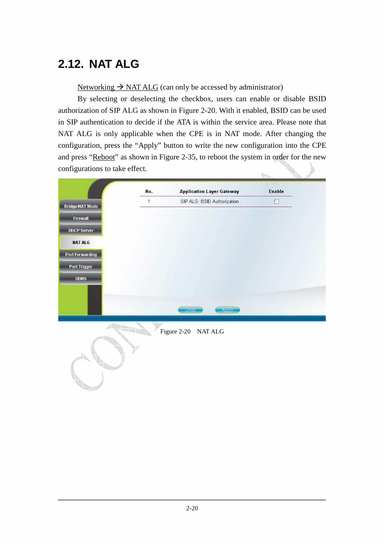
By selecting or deselecting the checkbox, users can enable or disable BSID
authorization of SIP ALG as shown in Figure 2-20. With it enabled, BSID can be used
in SIP authentication to decide if the ATA is within the service area. Please note that
NAT ALG is only applicable when the CPE is in NAT mode. After changing the
configuration, press the “Apply” button to write the new configuration into the CPE
and press “Reboot” as shown in Figure 2-35, to reboot the system in order for the new
configurations to take effect.
Figure 2-20 NAT ALG
2-21
2.13. Port Forwarding
Networking � Port Forwarding
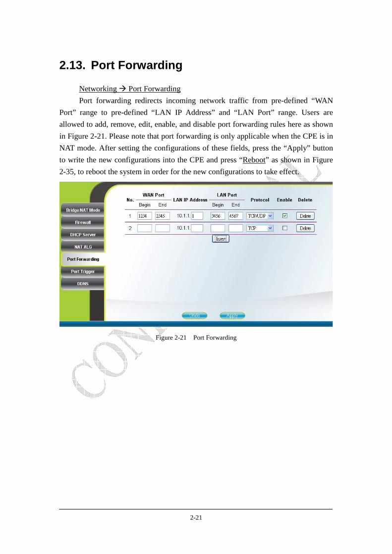
Port forwarding redirects incoming network traffic from pre-defined “WAN
Port” range to pre-defined “LAN IP Address” and “LAN Port” range. Users are
allowed to add, remove, edit, enable, and disable port forwarding rules here as shown
in Figure 2-21. Please note that port forwarding is only applicable when the CPE is in
NAT mode. After setting the configurations of these fields, press the “Apply” button
to write the new configurations into the CPE and press “Reboot” as shown in Figure
2-35, to reboot the system in order for the new configurations to take effect.
Figure 2-21 Port Forwarding
2-22
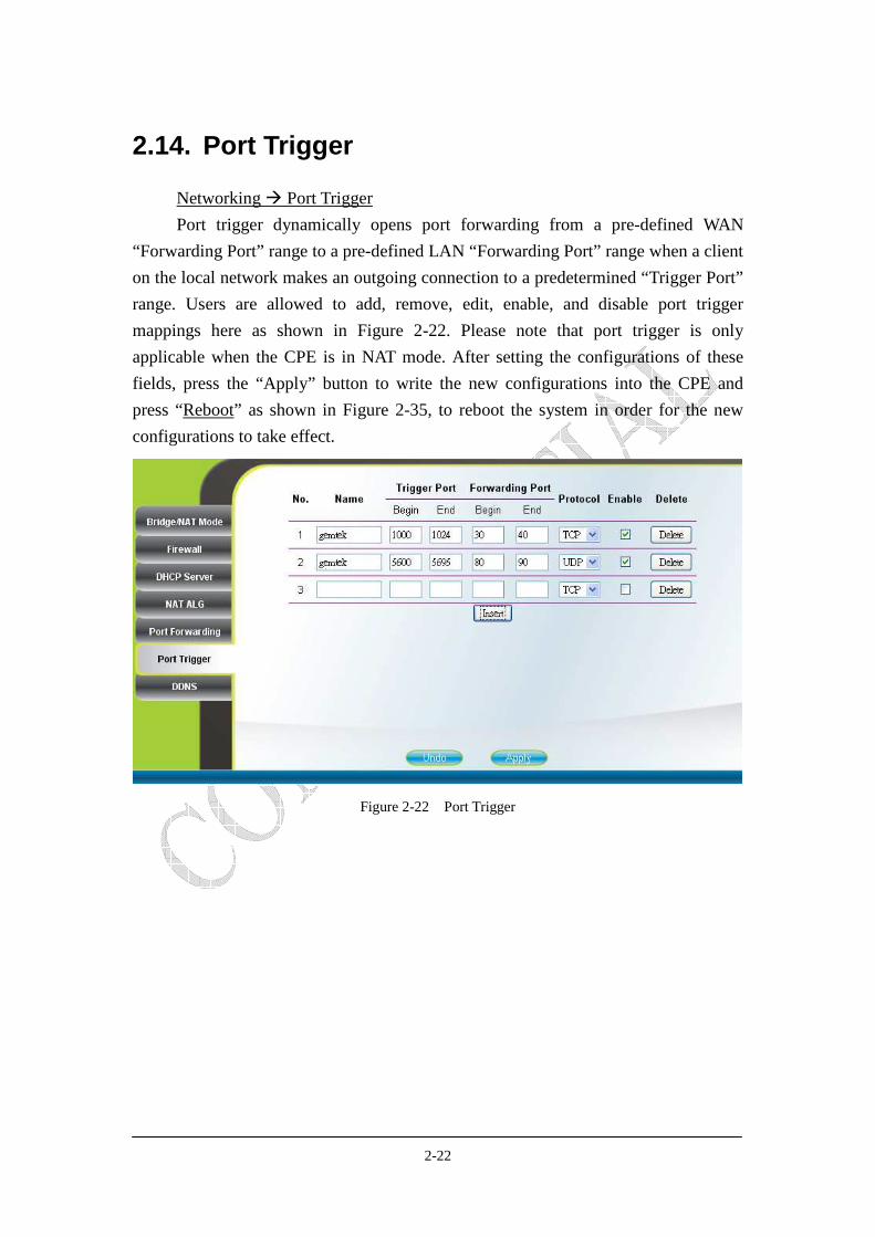
2.14. Port Trigger
Networking � Port Trigger
Port trigger dynamically opens port forwarding from a pre-defined WAN
“Forwarding Port” range to a pre-defined LAN “Forwarding Port” range when a client
on the local network makes an outgoing connection to a predetermined “Trigger Port”
range. Users are allowed to add, remove, edit, enable, and disable port trigger
mappings here as shown in Figure 2-22. Please note that port trigger is only
applicable when the CPE is in NAT mode. After setting the configurations of these
fields, press the “Apply” button to write the new configurations into the CPE and
press “Reboot” as shown in Figure 2-35, to reboot the system in order for the new
configurations to take effect.
Figure 2-22 Port Trigger
2-23
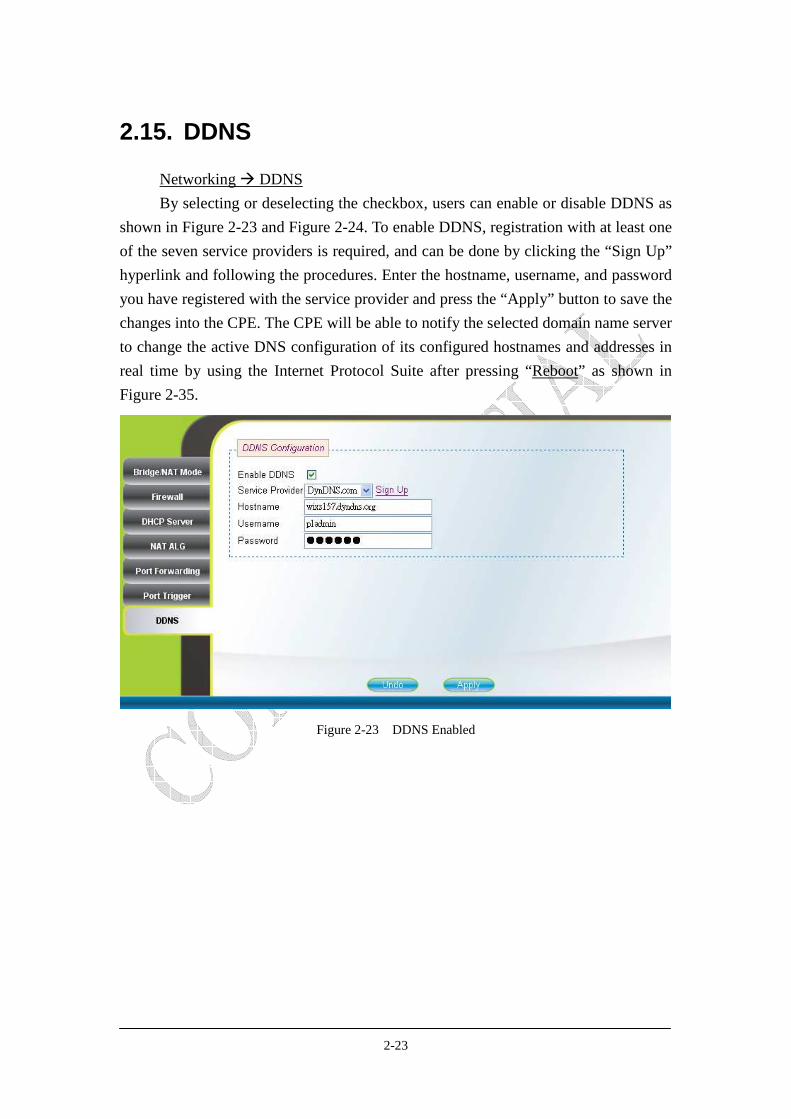
2.15. DDNS
Networking � DDNS
By selecting or deselecting the checkbox, users can enable or disable DDNS as
shown in Figure 2-23 and Figure 2-24. To enable DDNS, registration with at least one
of the seven service providers is required, and can be done by clicking the “Sign Up”
hyperlink and following the procedures. Enter the hostname, username, and password
you have registered with the service provider and press the “Apply” button to save the
changes into the CPE. The CPE will be able to notify the selected domain name server
to change the active DNS configuration of its configured hostnames and addresses in
real time by using the Internet Protocol Suite after pressing “Reboot” as shown in
Figure 2-35.
Figure 2-23 DDNS Enabled

2-24
Figure 2-24 DDNS Disabled

2-25
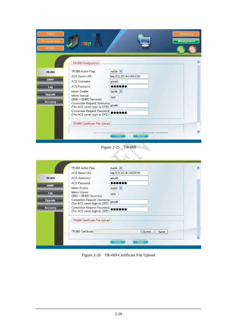
2.16. TR-069
Management � TR-069 (can only be accessed by administrator)
TR-069 client will automatically start up when the CPE is operational if the
“TR-069 Active Flag” is enabled. The “ACS Server URL” is the URL used by
TR-069 client to connect to the ACS server, and TR-069 client uses the “ACS
Username” and “ACS Password” to login the ACS Server. When the “Inform Enable”
is enabled, TR-069 client will periodically query the ACS server according to the
“Inform Interval”. The ACS server can also use the “Connection Request Username”
and “Connection Request Password” to connect to the CPE and get/set parameter via
connection request mechanism. Nevertheless, all of the above parameters will be
overwritten if Option-43 is activated. However, the parameters changed by Option-43
will not be saved into the CPE. In other words, all of the above parameters will be
restored when the CPE reboots. TR-069 certificates required for HTTPS protocol can
be uploaded in the “TR-069 Certificate File Upload” section. Note that the only
certificate format supported is PEM (Privacy Enhanced Mail, Base64 encoded DER
certificate). Please confirm the format before uploading. Please refer to Figure 2-25
and Figure 2-26 for more details. After setting the configurations of these fields, press
the “Apply” button to write the new configurations into the CPE. If only the “Inform
Enable” and/or “Inform Interval” have been changed, then do nothing and the change
will take effect in the next inform interval; otherwise press “Reboot” as shown in
Figure 2-35, to reboot the system in order for the new configurations to take effect.
2-26
Figure 2-25 TR-069
Figure 2-26 TR-069-Certificate File Upload
2-27
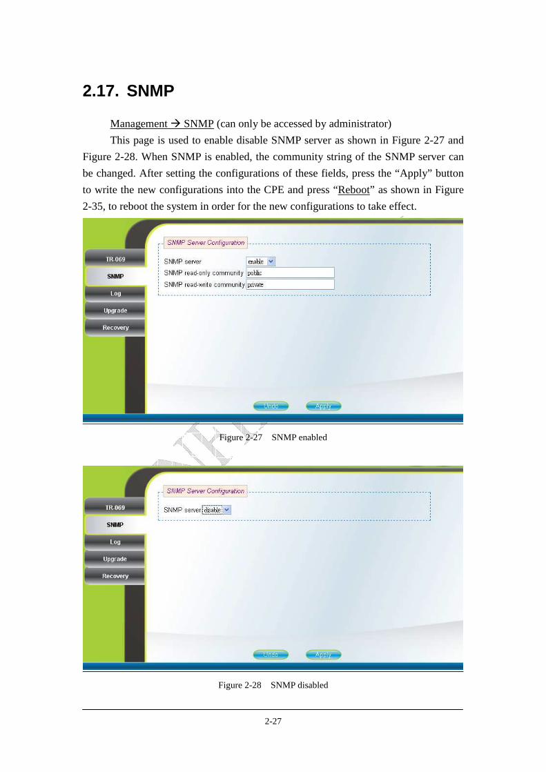
2.17. SNMP
Management � SNMP (can only be accessed by administrator)
This page is used to enable disable SNMP server as shown in Figure 2-27 and
Figure 2-28. When SNMP is enabled, the community string of the SNMP server can
be changed. After setting the configurations of these fields, press the “Apply” button
to write the new configurations into the CPE and press “Reboot” as shown in Figure
2-35, to reboot the system in order for the new configurations to take effect.
Figure 2-27 SNMP enabled
Figure 2-28 SNMP disabled
2-28
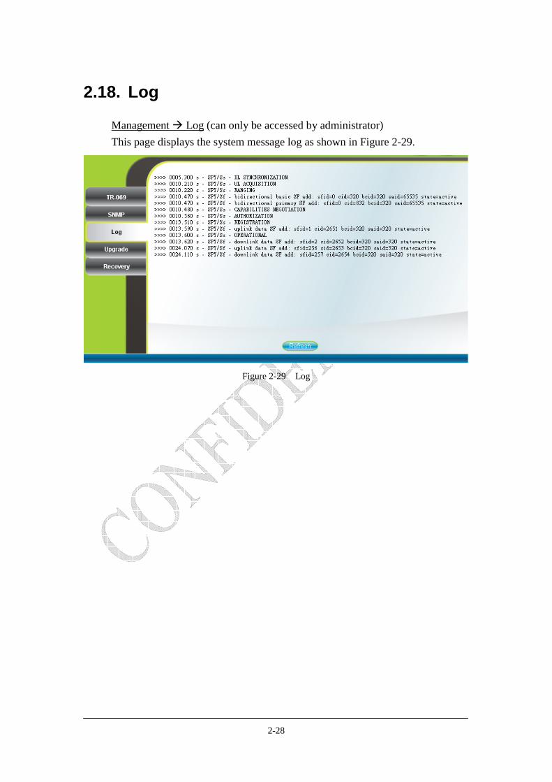
2.18. Log
Management � Log (can only be accessed by administrator)
This page displays the system message log as shown in Figure 2-29.
Figure 2-29 Log
2-29
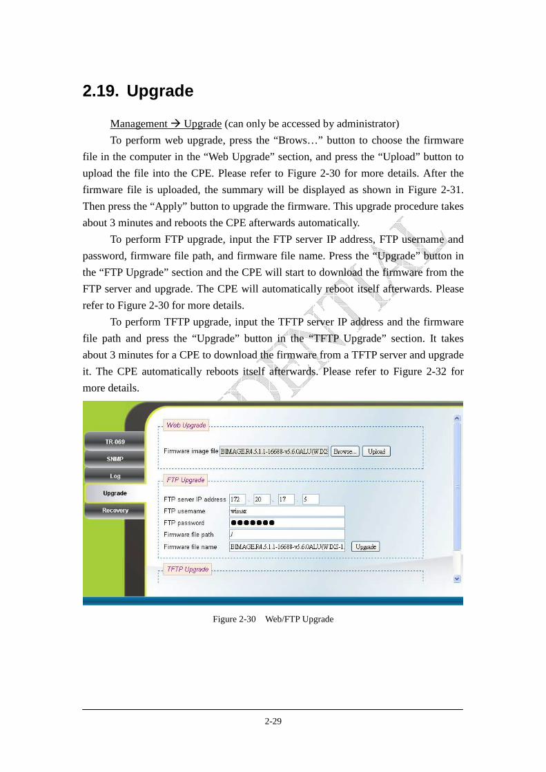
2.19. Upgrade
Management � Upgrade (can only be accessed by administrator)
To perform web upgrade, press the “Brows…” button to choose the firmware
file in the computer in the “Web Upgrade” section, and press the “Upload” button to
upload the file into the CPE. Please refer to Figure 2-30 for more details. After the
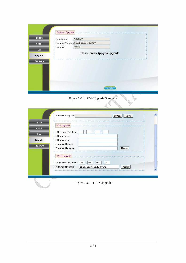
firmware file is uploaded, the summary will be displayed as shown in Figure 2-31.
Then press the “Apply” button to upgrade the firmware. This upgrade procedure takes
about 3 minutes and reboots the CPE afterwards automatically.
To perform FTP upgrade, input the FTP server IP address, FTP username and
password, firmware file path, and firmware file name. Press the “Upgrade” button in
the “FTP Upgrade” section and the CPE will start to download the firmware from the
FTP server and upgrade. The CPE will automatically reboot itself afterwards. Please
refer to Figure 2-30 for more details.
To perform TFTP upgrade, input the TFTP server IP address and the firmware
file path and press the “Upgrade” button in the “TFTP Upgrade” section. It takes
about 3 minutes for a CPE to download the firmware from a TFTP server and upgrade
it. The CPE automatically reboots itself afterwards. Please refer to Figure 2-32 for
more details.
Figure 2-30 Web/FTP Upgrade
2-30
Figure 2-31 Web Upgrade Summary
Figure 2-32 TFTP Upgrade
2-31
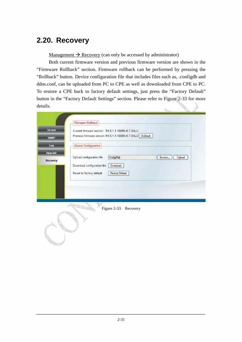
2.20. Recovery
Management � Recovery (can only be accessed by administrator)
Both current firmware version and previous firmware version are shown in the
“Firmware Rollback” section. Firmware rollback can be performed by pressing the
“Rollback” button. Device configuration file that includes files such as, .configdb and
ddns.conf, can be uploaded from PC to CPE as well as downloaded from CPE to PC.
To restore a CPE back to factory default settings, just press the “Factory Default”
button in the “Factory Default Settings” section. Please refer to Figure 2-33 for more
details.
Figure 2-33 Recovery
2-32
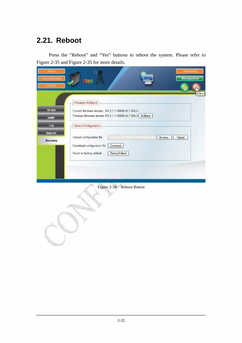
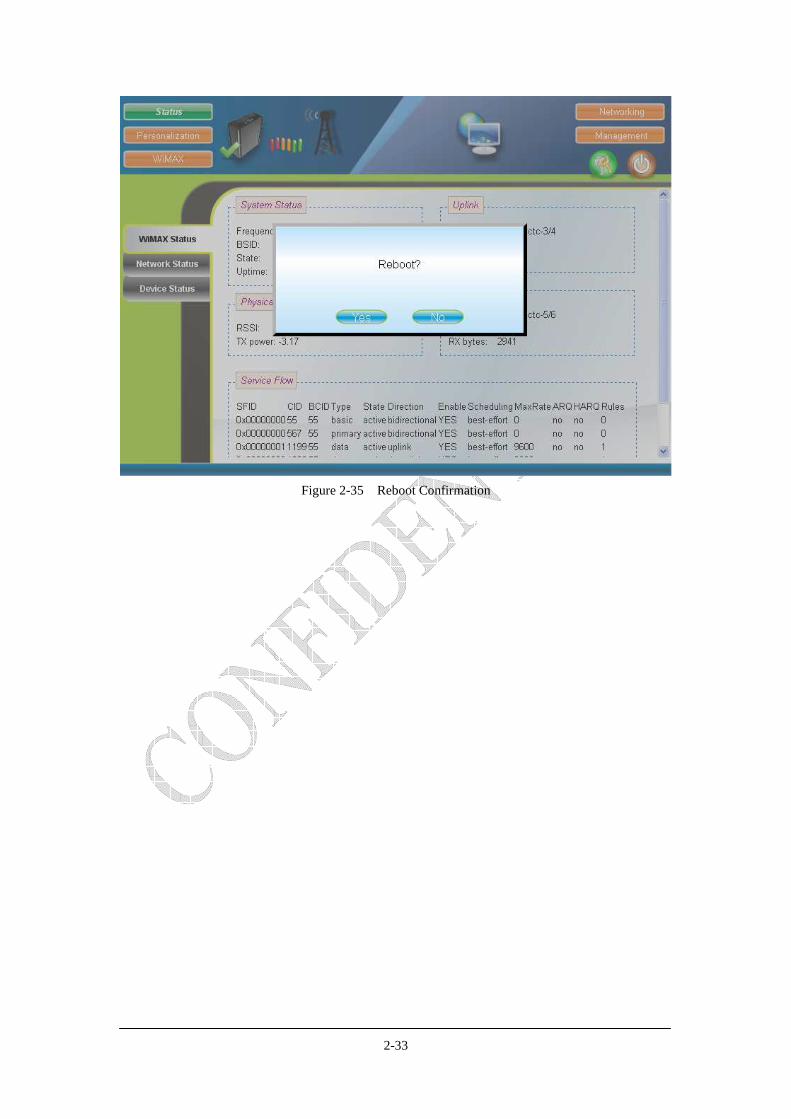
2.21. Reboot
Press the “Reboot” and “Yes” buttons to reboot the system. Please refer to
Figure 2-35 and Figure 2-35 for more details.
Figure 2-34 Reboot Button
2-33
Figure 2-35 Reboot Confirmation

2-34
Federal Communication Commission Interference Statement
This equipment has been tested and found to comply with the limits for a Class
B digital device, pursuant to Part 15 of the FCC Rules. These limits are
designed to provide reasonable protection against harmful interference in a
residential installation. This equipment generates, uses and can radiate radio
frequency energy and, if not installed and used in accordance with the
instructions, may cause harmful interference to radio communications.
However, there is no guarantee that interference will not occur in a particular
installation. If this equipment does cause harmful interference to radio or
television reception, which can be determined by turning the equipment off and
on, the user is encouraged to try to correct the interference by one of the
following measures:
- Reorient or relocate the receiving antenna.
- Increase the separation between the equipment and receiver.
- Connect the equipment into an outlet on a circuit different from that to
which the receiver is connected.
- Consult the dealer or an experienced radio/TV technician for help.
FCC Caution: Any changes or modifications not expressly approved by the
party responsible for compliance could void the user's authority to operate this
equipment.
This device complies with Part 15 of the FCC Rules. Operation is subject to the
following two conditions: (1) This device may not cause harmful interference,
and (2) this device must accept any interference received, including
interference that may cause undesired operation.
IMPORTANT NOTE:
Radiation Exposure Statement:
This equipment complies with FCC radiation exposure limits set forth for an
uncontrolled environment. This equipment should be installed and operated
with minimum distance 22 cm between the radiator & your body.
This transmitter must not be co-located or operating in conjunction with any
other antenna or transmitter.
The availability of some specific channels and/or operational frequency bands
are country dependent and are firmware programmed at the factory to match
the intended destination. The firmware setting is not accessible by the end
user.

2-35
Due to the essential high output power natural of WiMAX device, use of this
device with other transmitter at the same time may exceed the FCC RF
exposure limit and such usage must be prohibited (unless such
co-transmission has been approved by FCC in the future).


![Bobcat GEV Linux Installer Manual - Imperx Website...[users@testbuilder ~]$ ifconfig enp5s0 inet 10.10.0.1 netmask 255.255.255.0 Verify interfaces are setup. [users@testbuilder ~]$](https://img.pdfslide.us/doc/110x75/5e4638e19c2c385f6f638691/bobcat-gev-linux-installer-manual-imperx-website-userstestbuilder-ifconfig.jpg)


![Cisco TelePresence MCU 4500 Series Getting started · static A [] ... Creating conferences To create a conference:](https://img.pdfslide.us/doc/110x75/6032b7b62512c65c245d7c88/cisco-telepresence-mcu-4500-series-getting-started-static-a-creating-conferences.jpg)