Embed Size (px)
Citation preview

SMB Public Access Controller G-4200
User’s Guide
Revision 3.8 June 21, 2005
Copyright © 2002-2004 Gemtek Systems Holding BV www.gemtek-systems.com

Gemtek Systems Page 1
Copyright © 2002-2004 Gemtek Systems Holding BV.
This user’s guide and the software described in it are copyrighted with all rights reserved. No part of this publication may be reproduced, transmitted, transcribed, stored in a retrieval system, or translated into any language in any form by any means without the written permission of Gemtek Systems Holding BV.
Notice Gemtek Systems reserves the right to change specifications without prior notice.
While the information in this manual has been compiled with great care, it may not be deemed an assurance of product characteristics. Gemtek Systems shall be liable only to the degree specified in the terms of sale and delivery.
The reproduction and distribution of the documentation and software supplied with this product and the use of its contents is subject to written authorization from Gemtek Systems.
Trademarks The product described in this book is a licensed product of Gemtek Systems Holding BV.
Microsoft, Windows 95, Windows 98, Windows Millennium, Windows NT, Windows 2000, Windows XP, and MS-DOS are registered trademarks of the Microsoft Corporation.
Novell is a registered trademark of Novell, Inc.
MacOS is a registered trademark of Apple Computer, Inc.
Java is a trademark of Sun Microsystems, Inc.
Wi-Fi is a registered trademark of Wi-Fi Alliance.
All other brand and product names are trademarks or registered trademarks of their respective holders.
User’s Guide Version 3.8
Gemtek Systems Page 2
Copyright .............................................................................................................................................1 Notice ..................................................................................................................................................1 Trademarks .........................................................................................................................................1
CONTENTS ............................................................................................................................................2
ABOUT THIS GUIDE..............................................................................................................................5
Purpose ...............................................................................................................................................5 Prerequisite Skills and Knowledge......................................................................................................5 Conventions Used in this Document ...................................................................................................5 Help Us to Improve this Document! ....................................................................................................5 Gemtek Systems Technical Support...................................................................................................5
CHAPTER 1 – INTRODUCTION ............................................................................................................6
Product Overview ................................................................................................................................6 Management Options ..........................................................................................................................6 Access Controller Features.................................................................................................................7
CHAPTER 2 – INSTALLATION .............................................................................................................8
The Product Package..........................................................................................................................8 Hardware Introduction .........................................................................................................................9
General Overview ............................................................................................................................9 Back Panel.......................................................................................................................................9 LEDs ................................................................................................................................................9 Connectors.....................................................................................................................................10
Connecting the Access Controller.....................................................................................................11 Initialization........................................................................................................................................12
Software Introduction: KickStart ....................................................................................................12 Access Your G-4200......................................................................................................................12
Step by Step Setup ...........................................................................................................................16
CHAPTER 3 – UNIVERSAL ADDRESS TRANSLATION ...................................................................19
What is UAT ......................................................................................................................................19 UAT Principle ....................................................................................................................................19 UAT Limitation...................................................................................................................................19
CHAPTER 4 – USER PAGES (BASED ON XSL)................................................................................21
User Pages Overview........................................................................................................................22 Welcome Page...............................................................................................................................22 Login Page.....................................................................................................................................22 Logout Page...................................................................................................................................23 Help Page ......................................................................................................................................24 Unauthorized Page ........................................................................................................................24
Changing User Pages .......................................................................................................................25 Example for External Pages ..........................................................................................................25 Example for Internal Pages ...........................................................................................................28
CHAPTER 5 – CUSTOMIZED USER PAGE (HTML) ..........................................................................31
Determine Your Access Policy..........................................................................................................31 Configure Authentication-Free Access Policy ...................................................................................31 FAQ ...................................................................................................................................................36
CHAPTER 6 – COMMAND LINE INTERFACE....................................................................................38
Contents

User’s Guide Version 3.8
Gemtek Systems Page 3
Introduction........................................................................................................................................38 Get Connection to CLI.......................................................................................................................38
Telnet Connection..........................................................................................................................38 SSH Connection ............................................................................................................................38
Login..................................................................................................................................................39 Connection ........................................................................................................................................39 Network .............................................................................................................................................40 User ...................................................................................................................................................42 Status ................................................................................................................................................43 System...............................................................................................................................................43 Telnet.................................................................................................................................................44 Reboot ...............................................................................................................................................44 Reset .................................................................................................................................................44 Exit.....................................................................................................................................................44
CHAPTER 7 – SNMP MANAGEMENT................................................................................................45
Introduction........................................................................................................................................45 SNMP Versions .................................................................................................................................45 SNMP Agent......................................................................................................................................46 SNMP Community Strings.................................................................................................................46 Use SNMP to Access MIB.................................................................................................................47 Gemtek Private MIB ..........................................................................................................................47
CHAPTER 8 – REFERENCE MANUAL...............................................................................................48
Web Interface ....................................................................................................................................48 Network Interface ..............................................................................................................................50
Network Interface | Configuration | Interface Configuration...........................................................50 Network Interface | Configuration | VLAN......................................................................................51 Network Interface | Configuration | Route......................................................................................52 Network Interface | Configuration | Port Forwarding .....................................................................53 Network Interface | Configuration | DHCP Relay...........................................................................54 Network Interface | Configuration | User ACL................................................................................54 Network Interface | Configuration | Management Subnet..............................................................55 Network Interface | DNS ................................................................................................................56 Network Interface | DHCP .............................................................................................................57 Network Interface | RADIUS ..........................................................................................................59 Network Interface | RADIUS | RADIUS Settings ...........................................................................60 Network Interface | RADIUS | RADIUS Servers............................................................................62 Network Interface | RADIUS | WISP..............................................................................................64 Network Interface | RADIUS | Proxy..............................................................................................65 Network Interface | RADIUS | Accounting Backup ........................................................................66 Network Interface | Tunnels...........................................................................................................67 Network Interface | Tunnels | PPPoE/GRE ...................................................................................67 Network Interface | Tunnels | GRE Client for VPN ........................................................................68
User Interface....................................................................................................................................69 User Interface | Configuration | Pages...........................................................................................70 User Interface | Configuration | Upload .........................................................................................71 User Interface | Configuration | Headers .......................................................................................71 User Interface | Configuration | Custom Uam................................................................................72 User Interface | Administrator ........................................................................................................75 User Interface | Start Page ............................................................................................................77 User Interface | Walled Garden .....................................................................................................77 User Interface | Web Proxy............................................................................................................78
System...............................................................................................................................................79 System | Configuration | Syslog.....................................................................................................79 System | Configuration | Trace System .........................................................................................80 System | Configuration | Clock ......................................................................................................80 System | Configuration | NTP ........................................................................................................81

User’s Guide Version 3.8
Gemtek Systems Page 4
System | Configuration | Certificate ...............................................................................................82 System | Configuration | Save and Restore...................................................................................83 System | Configuration | Domain Name ........................................................................................84 System | Configuration | Share Username ....................................................................................85 System | Access | Access Control .................................................................................................85 System | Access | Telnet ...............................................................................................................87 System | Access | AAA ..................................................................................................................87 System | Access | UAT ..................................................................................................................88 System | Access | Isolation............................................................................................................89 System | Access | NAV..................................................................................................................89 System | Access | SNMP...............................................................................................................90 System | Access | Web Auth..........................................................................................................92 System | Access | Mac List ............................................................................................................93 System | Access | HTTPC .............................................................................................................93 System | Status..............................................................................................................................93 System | Reset...............................................................................................................................96 System | Update ............................................................................................................................97
Connection ........................................................................................................................................99 Connection | Users ........................................................................................................................99 Connection | E-mail Redirection ..................................................................................................101 Connection | Station Supervision.................................................................................................101
Built-In AAA .....................................................................................................................................102 Built-in AAA | E-Billing .................................................................................................................102 Built-in AAA | E-Billing | User Control ..........................................................................................102 Built-in AAA | E-Billing | Band Class ............................................................................................104 Built-in AAA | E-Billing | Bill setting ..............................................................................................105 Built-in AAA | E-Billing| Power cut protection...............................................................................106 Built-in AAA | pre-paid .................................................................................................................107 Built-in AAA | pre-paid | user account..........................................................................................107 Built-in AAA | pre-paid | price/unit................................................................................................108 Built-in AAA | pre-paid | account life ............................................................................................108 Built-in AAA | pre-paid | WEP key and SSID ...............................................................................108 Built-in AAA | pre-paid | receipts..................................................................................................108 Built-in AAA | pre-paid | account reminder...................................................................................109 Built-in AAA | Configuration | Language ......................................................................................109 Built-in AAA | Configuration | Backup and restore.......................................................................109 Built-in AAA | Configuration | title.................................................................................................109
APPENDIX..........................................................................................................................................111
A) Access Controller Specification ..................................................................................................111 Technical Data.............................................................................................................................111
B) Factory Defaults for the Access Controller .................................................................................113 C) CLI Commands and Parameters................................................................................................119
Network Commands ....................................................................................................................119 User Commands..........................................................................................................................123 System Commands .....................................................................................................................124 Status Commands .......................................................................................................................127 Connection Commands ...............................................................................................................127
E) Standard RADIUS Attributes ......................................................................................................128 Vendor Specific Attributes ...........................................................................................................129
F) Location ID and ISO Country Codes ..........................................................................................131 G) User Pages Templates Syntax...................................................................................................135
GLOSSARY ........................................................................................................................................140
INDEX .................................................................................................................................................144

User’s Guide Version 3.8
Gemtek Systems Page 5
Purpose This document provides information and procedures on hardware installation, setup, configuration, and management of the Gemtek Systems SMB Public Access Controller model G-4200 (version 2.22). The G-4200 is a highly integrated Access Controller with built-in AAA systems for public access hotspot. We will call it AC later in the manual.
Prerequisite Skills and Knowledge To use this document effectively, you should have a working knowledge of Local Area Networking (LAN) concepts and wireless Internet access infrastructures. In addition, you should be familiar with the following:
Hardware installers should have a working knowledge of basic electronics and mechanical assembly, and should understand related local building codes.
Network administrators should have a solid understanding of software installation procedures for network operating systems under Microsoft Windows 95, 98, Millennium, 2000, NT, and Windows XP and general networking operations and troubleshooting knowledge.
Conventions Used in this Document The following typographic conventions and symbols are used throughout this document:
Very important information. Failure to observe this may result in damage.
Important information that should be observed.
Additional information that may be helpful but which is not required.
bold Menu commands, buttons and input fields are displayed in bold code File names, directory names, form names, and system-generated output
such as error messages are displayed in constant-width type <value> Placeholder for certain values, e.g. user inputs
[value] Input field format, limitations, and/or restrictions.
Help Us to Improve this Document! If you should encounter mistakes in this document or want to provide comments to improve the manual please send e-mail directly to:
Gemtek Systems Technical Support If you encounter problems when installing or using this product, please consult the Gemtek Systems website at www.gemtek-systems.com for:
Direct contact to the Gemtek Systems support centers. Frequently Asked Questions (FAQ). Download area for the latest software, user documentation and product updates.
About this Guide
User’s Guide Version 3.8
Gemtek Systems Page 6
Thank you for choosing the Gemtek Systems SMB Public Access Controller.
The Gemtek Systems G-4200 is a high performance and highly integrated Access Controller for public access networks. It combines an IP Router, a 4-port LAN Switch and a complete Access Controller for Wi-Fi Hotspots in one box. One single G-4200 can serve up to 200 simultaneous users, takes control over authentication, accounting and routing to the Internet as well as to the operator’s central. Built-in AAA systems make hotspot owners setup public access services without any RADIUS server.
Product Overview Scalable With Customer Needs
Authentication, Authorization & Accounting The G-4200 supports multiple secure authentication methods from standard web browser login (Universal Access Method), MAC authentication, to 802.1x/EAP with passwords, certificates or SIM cards. The integrated real-time accounting system is based on standard RADIUS/EAP and supports various billing plans from prepaid, pay-per-time, per-volume, per-use or flat rate. Integration into existing OSS/BSS systems can be done with ease.
Service Differentiation The integrated Web server of the G-4200 allows flexible interaction with common web application servers, facilitating the provisioning of differentiated services with bandwidth management, location based and personalized services. Inter-Provider roaming and multi-OSS support is guaranteed by the persistent usage of standardized protocols and interfaces like RADIUS, HTTPS and XML. As all Gemtek Systems Access Controllers G-4200 is compliant with the recommendations of the Wi-Fi Alliance WISP roaming group.
Remote Control The G-4200 SMB PAC is placed at the edge of a broadband access network and allows operators to provide cost effective public Wi-Fi services, by managing per user access control, device configuration, and radio performance centrally from the operations centre. HTTPs, telnet, SSH or SNMP over VPN can be used for secure remote management.
Privacy G-4200 supports different levels of security and data encryption. Client stations can be separated at the link layer (Layer2 User Isolation), preventing intruders from accessing the hard discs of other users. User credentials (passwords) are protected by SSL or EAP-based authentication methods. User traffic can be encrypted by VPNs (pass-through). Operators and service providers can make use of the integrated VPN/tunneling protocols to protect AAA and management traffic.
Management Options You can use the Access Controller management systems through the following interfaces:
Web-browser interface Command Line interface (CLI) Simple Network Management Protocol (SNMP v1, v2, v3)
The AC management system pages are organized the same way for the web-browser interface and the CLI. This user manual provides detailed description of each management option.
Chapter 1 – Introduction

User’s Guide Version 3.8
Gemtek Systems Page 7
Access Controller Features AAA
Multiple authentication methods: UAM, 802.1x/EAP, RADIUS, MAC, Smart Client (e.g. iPass) WISPr compliant Internal and external accounting backups Internal or external web server Remote user login, logout, session status control via https/XML AAA proxy server (for simultaneous EAP and UAM) Per user bandwidth management Web proxy support
IP Router and IP address management
Static IP routing table NAT/NAPT (IP masquerading) Port-forwarding Transparent VPN client pass-through (PPTP, IPsec ESP) PPPoE client DHCP server, relay gateway (suboptions), DHCP client UAT (Universal Address Translation) SMTP redirection (e-mail)
VPN
GRE VPN client, max. 16 tunnels
LAN switch
Managed 4-port switch 10/100Mb, auto-sensing
Management
Secure management via https, SSH, SNMP SNMP proxy SNMPv3 (incl. authentication and encryption) Management subnet for remote AP and switch management Remote firmware update

User’s Guide Version 3.8
Gemtek Systems Page 8
This chapter provides installation instructions for the hardware and software components of the Access Controller G-4200. It also includes the procedures for the following tasks:
Hardware Introduction (LEDs, Connectors) Connecting the Access Controller First Configuration Step-by-Step Setup
The Product Package The Access Controller comes with the following:
SMB Public Access Controller (model: G-4200) 2 Housing brackets with screws in PE bag Power cord 1.7m USA Type black Power cord 1.7m Euro Type black 1.8m RJ45 Cat.5 UTP cable Printed Warranty sheet Printed Release note Installation CD containing:
G-4200 User Guide in PDF format KickStart Utility Product Firmware Templates for login and logout page (HTML) Release Notes Adobe Acrobat Readers
If any of these items are missing or damaged, please contact your reseller or Gemtek System sales representative.
Chapter 2 – Installation
User’s Guide Version 3.8
Gemtek Systems Page 9
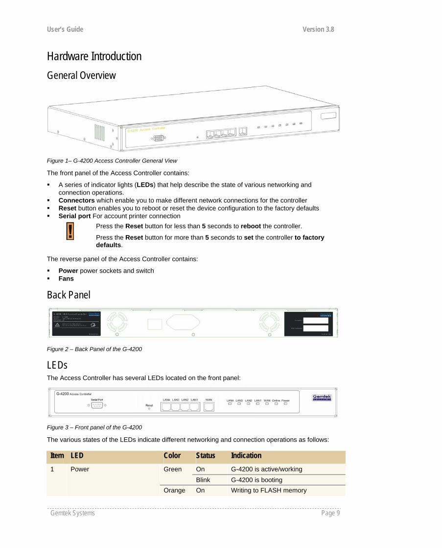
Hardware Introduction General Overview
Figure 1– G-4200 Access Controller General View
The front panel of the Access Controller contains:
A series of indicator lights (LEDs) that help describe the state of various networking and connection operations.
Connectors which enable you to make different network connections for the controller Reset button enables you to reboot or reset the device configuration to the factory defaults Serial port For account printer connection
Press the Reset button for less than 5 seconds to reboot the controller.
Press the Reset button for more than 5 seconds to set the controller to factory defaults.
The reverse panel of the Access Controller contains:
Power power sockets and switch Fans
Back Panel
Figure 2 – Back Panel of the G-4200
LEDs The Access Controller has several LEDs located on the front panel:
Figure 3 – Front panel of the G-4200
The various states of the LEDs indicate different networking and connection operations as follows: Item LED Color Status Indication
On G-4200 is active/working Green Blink G-4200 is booting
1 Power
Orange On Writing to FLASH memory
User’s Guide Version 3.8
Gemtek Systems Page 10
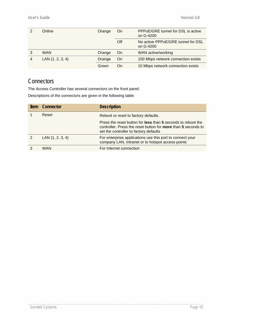
On PPPoE/GRE tunnel for DSL is active on G-4200
2 Online Orange
Off No active PPPoE/GRE tunnel for DSL on G-4200
3 WAN Orange On WAN active/working Orange On 100 Mbps network connection exists 4 LAN (1, 2, 3, 4)
Green On 10 Mbps network connection exists
Connectors The Access Controller has several connectors on the front panel:
Descriptions of the connectors are given in the following table:
Item Connector Description 1 Reset Reboot or reset to factory defaults.
Press the reset button for less than 5 seconds to reboot the controller. Press the reset button for more than 5 seconds to set the controller to factory defaults
2 LAN (1, 2, 3, 4) For enterprise applications use this port to connect your company LAN, Intranet or to hotspot access points
3 WAN For Internet connection

User’s Guide Version 3.8
Gemtek Systems Page 11
Connecting the Access Controller
Use the following procedure to prepare your network connection to the Access Controller.
Step 1 Place the Access Controller on a flat work surface.
Step 2 Connect one Ethernet patch cable to the LAN port of the Access Controller and to a free hub port on your local network.
Step 3 Connect one Ethernet patch cable to the WAN port of the Access Controller and to an Ethernet port of a broadband Internet modem or router.
Step 4 Connect the power cord to the Access Controller.
Step 5 Wait 30 seconds until the boot process is finished and check to ensure that at least the following LEDs are ON:
Power LED (steady On)
WAN LED
LAN LED

User’s Guide Version 3.8
Gemtek Systems Page 12
Initialization There are two choices for the first web browser connection to your Access Controller: either you enter your access controller's IP address and subnet (default networks settings) into the browser or you launch the KickStart utility that is provided with your product CD.
The default network settings for your new access controller are:
LAN port: IP 192.168.3.1 subnet 255.255.255.0
WAN port: IP 192.168.2.66 subnet 255.255.255.0
DHCP Server: enabled for LAN port
For other management methods: SNMP and command line interface (CLI) please refer to their respective chapters.
Software Introduction: KickStart The Gemtek Systems KickStart is a software utility that is included on the Installation CD.
The utility automatically detects access points and access controllers installed on your network, regardless of its host IP address and lets you configure each unit’s IP settings. The feature list for the KickStart utility is listed below:
Scanning your subnet for all connected APs, ACs Quick access to your AC via HTTPS, telnet, SSH Setting new IP address of your AC Reset to factory default settings Default access (in case of lost administrator password) Firmware updates
To install the KickStart utility insert the Installation CD into your CD-ROM drive. Find and install the utility from the product CD into the computer.
Access Your G-4200 There are two choices for the first Web browser connection to your access controller:
Use the Web browser. Launch the KickStart utility that is provided with your product CD.
If first method is preferred follow these instructions:
Step 1 Configure your PC with a static IP address on the 192.168.2.0 subnet with mask 255.255.255.0. Connect to the WAN interface of G-4200 which in to the same physical network as your PC. Open the Web browser and type the default IP address of the G-4200:
https://192.168.2.66/a.rg
Step 2 Enter the G-4200 administrator login details to access the Web management.
If the Installation CD does not start automatically, please run “autorun.exe” manually from the root directory of the installation CD.
User’s Guide Version 3.8
Gemtek Systems Page 13
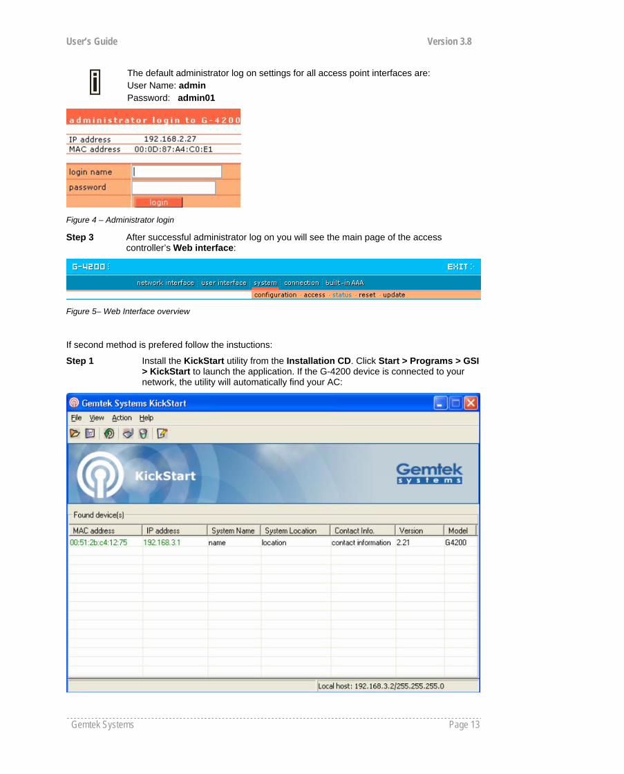
The default administrator log on settings for all access point interfaces are: User Name: admin Password: admin01
Figure 4 – Administrator login
Step 3 After successful administrator log on you will see the main page of the access controller’s Web interface:
Figure 5– Web Interface overview
If second method is prefered follow the instuctions:
Step 1 Install the KickStart utility from the Installation CD. Click Start > Programs > GSI > KickStart to launch the application. If the G-4200 device is connected to your network, the utility will automatically find your AC:
User’s Guide Version 3.8
Gemtek Systems Page 14
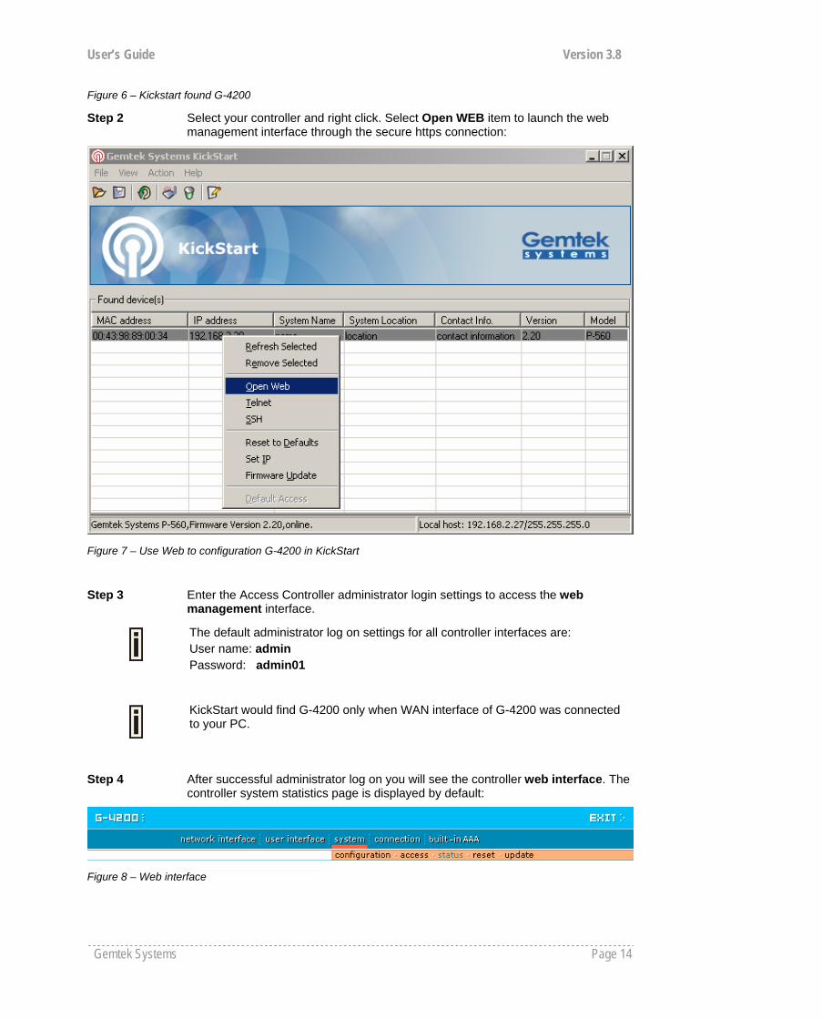
Figure 6 – Kickstart found G-4200
Step 2 Select your controller and right click. Select Open WEB item to launch the web management interface through the secure https connection:
Figure 7 – Use Web to configuration G-4200 in KickStart
Step 3 Enter the Access Controller administrator login settings to access the web management interface.
The default administrator log on settings for all controller interfaces are: User name: admin Password: admin01
KickStart would find G-4200 only when WAN interface of G-4200 was connected to your PC.
Step 4 After successful administrator log on you will see the controller web interface. The controller system statistics page is displayed by default:
Figure 8 – Web interface

User’s Guide Version 3.8
Gemtek Systems Page 15
If you cannot connect to the device via your web browser because of TCP/IP mis-configuration, you can reset the product to the factory default. Press the reset button for more than 5 seconds.
Now you are enabled to perform the initial controller configuration. Follow the next section for step-by-step setup instruction to configure the device according to your needs.
User’s Guide Version 3.8
Gemtek Systems Page 16
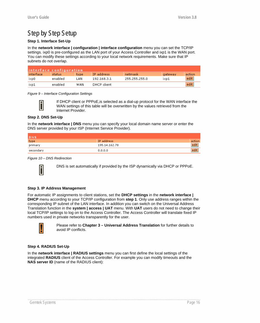
Step by Step Setup Step 1. Interface Set-Up
In the network interface | configuration | interface configuration menu you can set the TCP/IP settings. ixp0 is pre-configured as the LAN port of your Access Controller and ixp1 is the WAN port. You can modify these settings according to your local network requirements. Make sure that IP subnets do not overlap.
Figure 9 – Interface Configuration Settings
If DHCP client or PPPoE,is selected as a dial-up protocol for the WAN interface the WAN settings of this table will be overwritten by the values retrieved from the Internet Provider.
Step 2. DNS Set-Up
In the network interface | DNS menu you can specify your local domain name server or enter the DNS server provided by your ISP (Internet Service Provider).
Figure 10 – DNS Redirection
DNS is set automatically if provided by the ISP dynamically via DHCP or PPPoE.
Step 3. IP Address Management
For automatic IP assignments to client stations, set the DHCP settings in the network interface | DHCP menu according to your TCP/IP configuration from step 1. Only use address ranges within the corresponding IP subnet of the LAN interface. In addition you can switch on the Universal Address Translation function in the system | access | UAT menu. With UAT users do not need to change their local TCP/IP settings to log on to the Access Controller. The Access Controller will translate fixed IP numbers used in private networks transparently for the user.
Please refer to Chapter 3 – Universal Address Translation for further details to avoid IP conflicts.
Step 4. RADIUS Set-Up
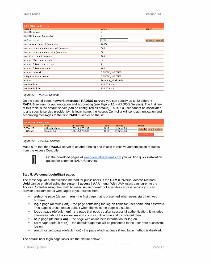
In the network interface | RADIUS settings menu you can first define the local settings of the integrated RADIUS client of the Access Controller. For example you can modify timeouts and the NAS server ID (name of the RADIUS client):
User’s Guide Version 3.8
Gemtek Systems Page 17
Figure 11 – RADIUS Settings
On the second page: network interface | RADIUS servers you can specify up to 32 different RADIUS servers for authentication and accounting (see Figure 12 – RADIUS Servers). The first line of this table is the default server (can be configured as default). Thus, if a user cannot be associated to any specific service provider by his login name, the Access Controller will send authentication and accounting messages to the first RADIUS server on the list.
Figure 12 – RADIUS Servers
Make sure that the RADIUS server is up and running and is able to receive authentication requests from the Access Controller.
On the download pages at www.gemtek-systems.com you will find quick installation guides for common RADIUS servers.
Step 5. Welcome/Login/Start pages
The most popular authentication method for public users is the UAM (Universal Access Method). UAM can be enabled using the system | access | AAA menu. With UAM users can log-on to the Access Controller using their web browser. As an operator of a wireless access service you can provide a custom set of web pages to your subscribers.
welcome page (default = on) - the first page that is presented when users start their web browser.
login page (default = on) – the page containing the log-on fields for user name and password. This page is presented as default when the welcome page is disabled.
logout page (default = on) - the page that pops up after successful authentication. It includes information about the online session such as online time and transferred data.
help page (default = on) - the page with online help information for log-on. start page (default = on) - the default-page that will be presented to the user after successful
log-on. unauthorized page (default = on) - the page which appears if web login method is disabled.
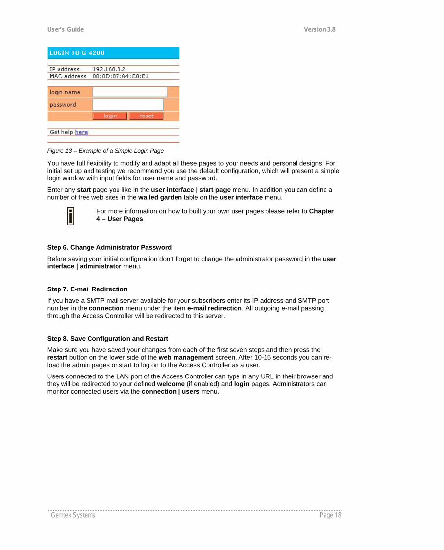
The default user login page looks like the picture below:
User’s Guide Version 3.8
Gemtek Systems Page 18
Figure 13 – Example of a Simple Login Page
You have full flexibility to modify and adapt all these pages to your needs and personal designs. For initial set up and testing we recommend you use the default configuration, which will present a simple login window with input fields for user name and password.
Enter any start page you like in the user interface | start page menu. In addition you can define a number of free web sites in the walled garden table on the user interface menu.
For more information on how to built your own user pages please refer to Chapter 4 – User Pages.
Step 6. Change Administrator Password
Before saving your initial configuration don’t forget to change the administrator password in the user interface | administrator menu.
Step 7. E-mail Redirection
If you have a SMTP mail server available for your subscribers enter its IP address and SMTP port number in the connection menu under the item e-mail redirection. All outgoing e-mail passing through the Access Controller will be redirected to this server.
Step 8. Save Configuration and Restart
Make sure you have saved your changes from each of the first seven steps and then press the restart button on the lower side of the web management screen. After 10-15 seconds you can re-load the admin pages or start to log on to the Access Controller as a user.
Users connected to the LAN port of the Access Controller can type in any URL in their browser and they will be redirected to your defined welcome (if enabled) and login pages. Administrators can monitor connected users via the connection | users menu.
User’s Guide Version 3.8
Gemtek Systems Page 19
What is UAT Universal Address Translation (UAT) allows Hotspot operators to offer true IP Plug&Play access for their subscribers.
With UAT enabled, the Access Controller will automatically and transparently translate fixed IP settings (IP address, gateway, DNS, proxy server) on a user’s PC enabling him to connect to the broadband Internet service, even if the client’s IP overlaps the IP subnet of the WAN port. Without UAT public access, subscribers are forced to switch their TCP/IP settings to DHCP (automatic IP address assignment), potentially losing any fixed IP address settings they previously entered.
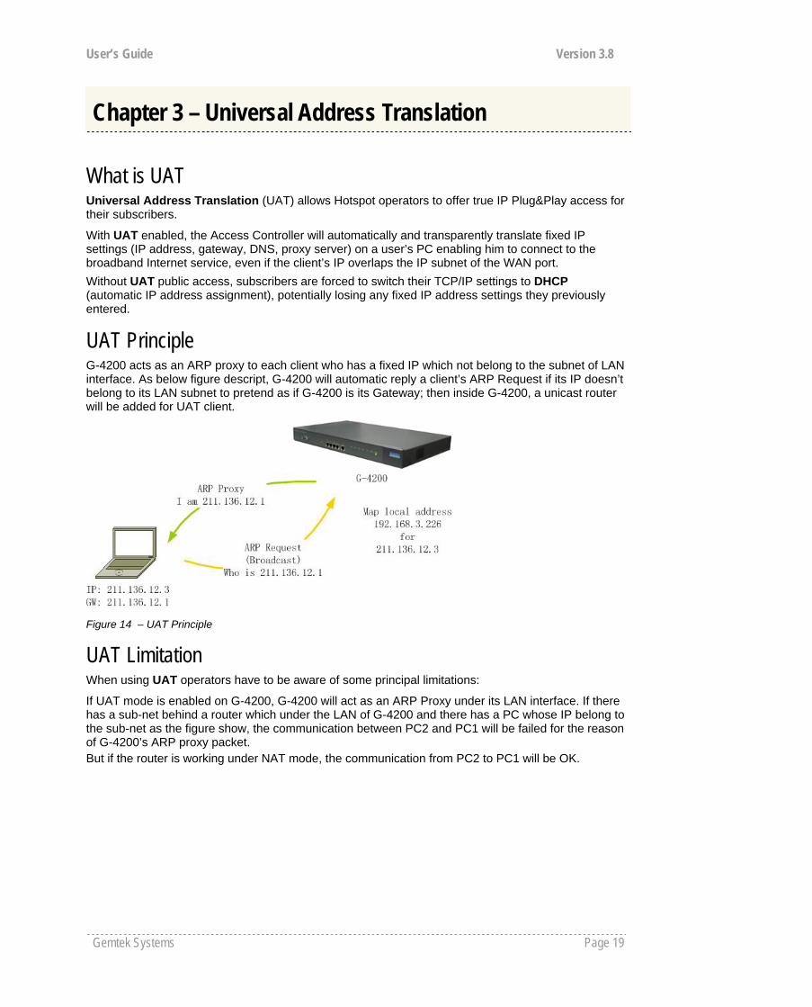
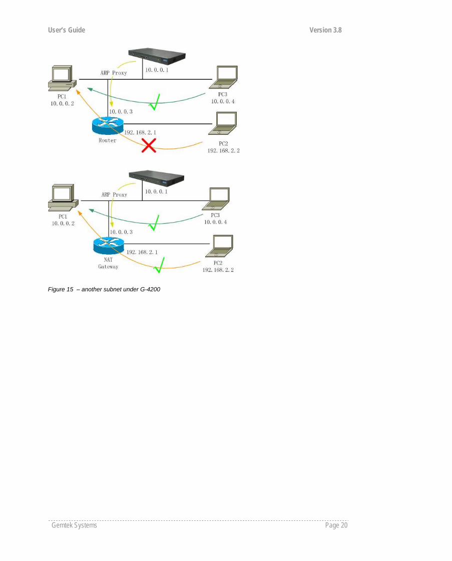
UAT Principle G-4200 acts as an ARP proxy to each client who has a fixed IP which not belong to the subnet of LAN interface. As below figure descript, G-4200 will automatic reply a client’s ARP Request if its IP doesn’t belong to its LAN subnet to pretend as if G-4200 is its Gateway; then inside G-4200, a unicast router will be added for UAT client.
Figure 14 – UAT Principle
UAT Limitation When using UAT operators have to be aware of some principal limitations:
If UAT mode is enabled on G-4200, G-4200 will act as an ARP Proxy under its LAN interface. If there has a sub-net behind a router which under the LAN of G-4200 and there has a PC whose IP belong to the sub-net as the figure show, the communication between PC2 and PC1 will be failed for the reason of G-4200’s ARP proxy packet. But if the router is working under NAT mode, the communication from PC2 to PC1 will be OK.
Chapter 3 – Universal Address Translation
User’s Guide Version 3.8
Gemtek Systems Page 20
Figure 15 – another subnet under G-4200

User’s Guide Version 3.8
Gemtek Systems Page 21
This chapter describes what the user pages are and how to manage them. Detailed instructions on how to change and upload new user pages are given below.
When launching his/her web browser the user's initial HTTP request will be redirected to an operator defined set of web pages, further called the "user pages". User pages are:
Welcome page– the first page presented to the user. Login page– subscriber authentication page, allows the user to login to the network. Logout page– small pop-up window for logged-on user statistics and log-out function. Help page – get help with the login process. Unauthorized page – this page is displayed when web login or EAP login methods are disabled
on the Access Controller for subscribers.
All further presented user pages are factory default. The Hotspot operator can upload new templates for all user pages.
Chapter 4 – User Pages (Based on XSL)

User’s Guide Version 3.8
Gemtek Systems Page 22
User Pages Overview Welcome Page Welcome page is the first page a Hotspot subscriber receives when he starts his web browser and enters any URL. By default it’s a very simple page and provides only a link to the login page.
Figure 16 – Welcome Page
The Hotspot operator can change the welcome page according its needs. See more details in section: Changing User Pages.
Login Page The subscriber gets to the login page after clicking the link on the welcome page. The login page is loaded from the Access Controller. To get access to the network, the user should enter his authentication settings: login name and password and click the login button:
Figure 17 – Simple Login Page
The login name and password can be obtained from your Hotspot Operator. Login format available for G-4200:
username@WISPdomain WISPdomain/username Prefix+ username (prefix length from 2 to 6, prefix can use the abbreviation
name of hotspot owner. For example GSI.) The login page also displays subscriber’s logical and physical network addresses (IP and MAC). Once authenticated, a start page appears. In addition, a smaller logout window (page) pops up.
The Hotspot operator can change the login page according to its needs. See more details in section: Changing User Pages.
User’s Guide Version 3.8
Gemtek Systems Page 23
Logout Page
Make sure the JavaScript is enabled on your Web browser; otherwise you will not receive the logout page.
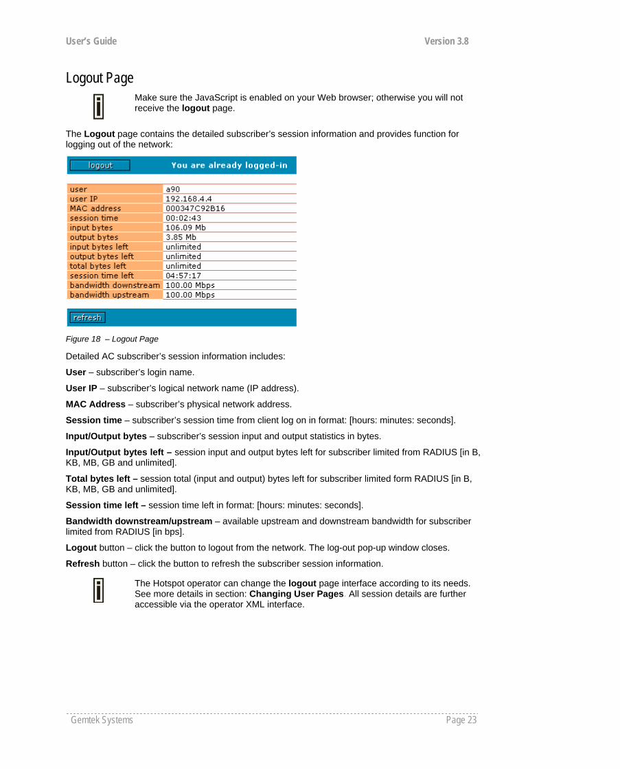
The Logout page contains the detailed subscriber’s session information and provides function for logging out of the network:
Figure 18 – Logout Page
Detailed AC subscriber’s session information includes:
User – subscriber’s login name.
User IP – subscriber’s logical network name (IP address).
MAC Address – subscriber’s physical network address.
Session time – subscriber’s session time from client log on in format: [hours: minutes: seconds].
Input/Output bytes – subscriber’s session input and output statistics in bytes.
Input/Output bytes left – session input and output bytes left for subscriber limited from RADIUS [in B, KB, MB, GB and unlimited].
Total bytes left – session total (input and output) bytes left for subscriber limited form RADIUS [in B, KB, MB, GB and unlimited].
Session time left – session time left in format: [hours: minutes: seconds].
Bandwidth downstream/upstream – available upstream and downstream bandwidth for subscriber limited from RADIUS [in bps].
Logout button – click the button to logout from the network. The log-out pop-up window closes.
Refresh button – click the button to refresh the subscriber session information.
The Hotspot operator can change the logout page interface according to its needs. See more details in section: Changing User Pages. All session details are further accessible via the operator XML interface.

User’s Guide Version 3.8
Gemtek Systems Page 24
Help Page Click on the get help link in the login page for help tips related to network registration. A page appears similar to the following:
Figure 19 – Help Page
The Hotspot operator can change the help page according to its needs. See more details in section: Changing User Pages.
Unauthorized Page If web log-on method (UAM) or EAP-based authentication methods are disabled on the AC and the subscriber attempts to login to the network, he will receive the following page:
Figure 20 – Unauthorized Page
The Hotspot operator can change the unauthorized page according to its needs. See more details in section: Changing User Pages.
User’s Guide Version 3.8
Gemtek Systems Page 25
Changing User Pages As the Hotspot operator you can modify the user pages freely according to your personal needs and preferences. User Page templates can be either stored locally on the AC or on an external web server.
See the Appendix: G) User Pages Templates Syntax to find the syntax and comments of all user pages.
Use the user interface | configuration menu to modify user pages. There are two ways to change and store new user page templates:
External – linking new user page templates from an external server. Internal – upload new templates to local memory.
Supported user pages template formats:
XSL (Extensible Style sheet Language) for welcome/login/logout/one click pages. HTML (Hypertext Markup Language for help/unauthorized pages.
The following image formats are supported for new templates. Other formats are not accepted:
PNG GIF JPG
The following examples demonstrate the use of internal and external user pages.
User Pages templates samples can be found in the Installation CD delivered to you with the product.
Example for External Pages
Step 1 Prepare your new user pages template for each user page: welcome/login/logout/help/unauthorized/oneclick.
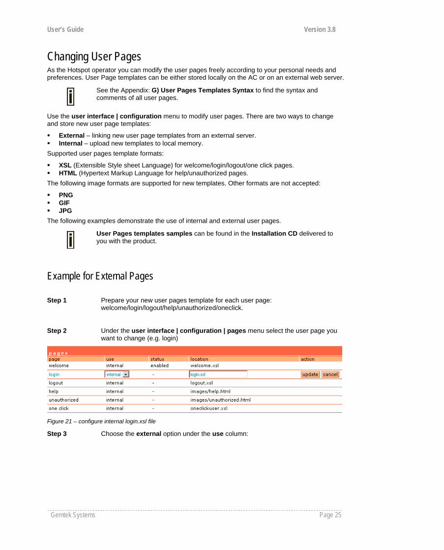
Step 2 Under the user interface | configuration | pages menu select the user page you want to change (e.g. login)
Figure 21 – configure internal login.xsl file
Step 3 Choose the external option under the use column:

User’s Guide Version 3.8
Gemtek Systems Page 26
Figure 22 – configure external login.xsl file
Step 4 Specify the new user page location in the location field (http://servername/filelocation):
Figure 23 – configure external login.xsl location field
Do not try to upload other than supported formats. Such uploaded pages will not be displayed properly.
Step 5 Save entered changes with the apply changes button:
Figure 24 – apply changes
Step 6 Check for new uploaded user page (e.g. login):
User’s Guide Version 3.8
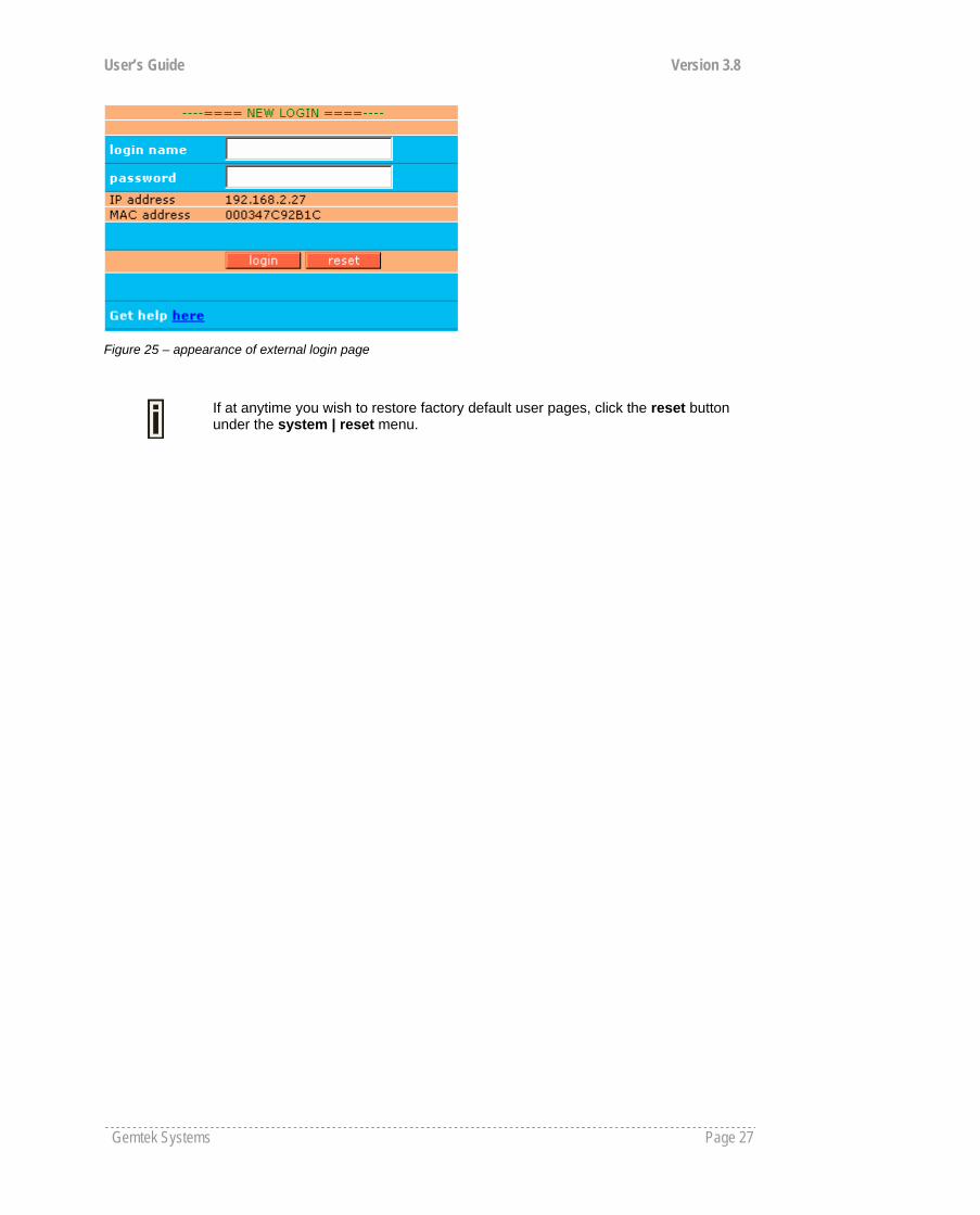
Gemtek Systems Page 27
Figure 25 – appearance of external login page
If at anytime you wish to restore factory default user pages, click the reset button under the system | reset menu.
User’s Guide Version 3.8
Gemtek Systems Page 28
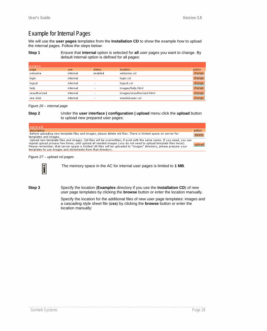
Example for Internal Pages We will use the user pages templates from the Installation CD to show the example how to upload the internal pages. Follow the steps below:
Step 1 Ensure that internal option is selected for all user pages you want to change. By default internal option is defined for all pages:
Figure 26 – internal page
Step 2 Under the user interface | configuration | upload menu click the upload button to upload new prepared user pages:
Figure 27 – upload xsl pages
The memory space in the AC for internal user pages is limited to 1 MB.
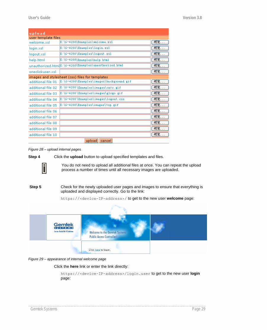
Step 3 Specify the location (Examples directory if you use the Installation CD) of new user page templates by clicking the browse button or enter the location manually.
Specify the location for the additional files of new user page templates: images and a cascading style sheet file (css) by clicking the browse button or enter the location manually:
User’s Guide Version 3.8
Gemtek Systems Page 29
Figure 28 – upload internal pages
Step 4 Click the upload button to upload specified templates and files.
You do not need to upload all additional files at once. You can repeat the upload process a number of times until all necessary images are uploaded.
Step 5 Check for the newly uploaded user pages and images to ensure that everything is uploaded and displayed correctly. Go to the link:
https://<device-IP-address>/ to get to the new user welcome page:
Figure 29 – appearance of internal welcome page
Click the here link or enter the link directly:
https://<device-IP-address>/login.user to get to the new user login page:
User’s Guide Version 3.8
Gemtek Systems Page 30
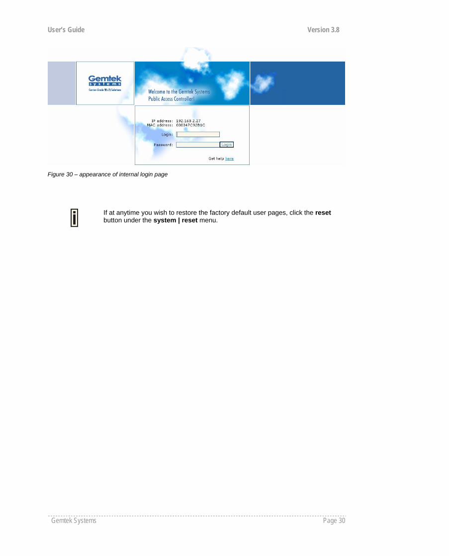
Figure 30 – appearance of internal login page
If at anytime you wish to restore the factory default user pages, click the reset button under the system | reset menu.
User’s Guide Version 3.8
Gemtek Systems Page 31
This chapter will assist you on configuring G-4200 customized login/logout pages using the sample templates in G-4200 CD. G-4200 CD includes four different styles of templates (based on HTML). There are three authentication-enabled styles (coffee bar, general and hotel), and one authentication-free hotel style. User can also create a personalized login/logout pages based on the provided sample templates.
Determine Your Access Policy Determine if the G-4200 access policy requires user authentication: Choose either the authentication-enabled policy (user authentication require) style template or authentication-free policy (no user authentication require) style template as the base template. Step 2 will show how to configure authentication-free access policy on G-4200. User may use any HTML editing tools to modify the template contents to create a new personalized login/logout page.
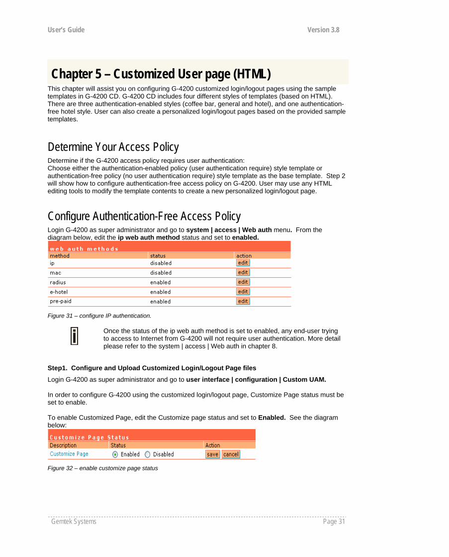
Configure Authentication-Free Access Policy Login G-4200 as super administrator and go to system | access | Web auth menu. From the diagram below, edit the ip web auth method status and set to enabled.
Figure 31 – configure IP authentication.
Once the status of the ip web auth method is set to enabled, any end-user trying to access to Internet from G-4200 will not require user authentication. More detail please refer to the system | access | Web auth in chapter 8.
Step1. Configure and Upload Customized Login/Logout Page files
Login G-4200 as super administrator and go to user interface | configuration | Custom UAM. In order to configure G-4200 using the customized login/logout page, Customize Page status must be set to enable. To enable Customized Page, edit the Customize page status and set to Enabled. See the diagram below:
Figure 32 – enable customize page status
Chapter 5 – Customized User page (HTML)
User’s Guide Version 3.8
Gemtek Systems Page 32
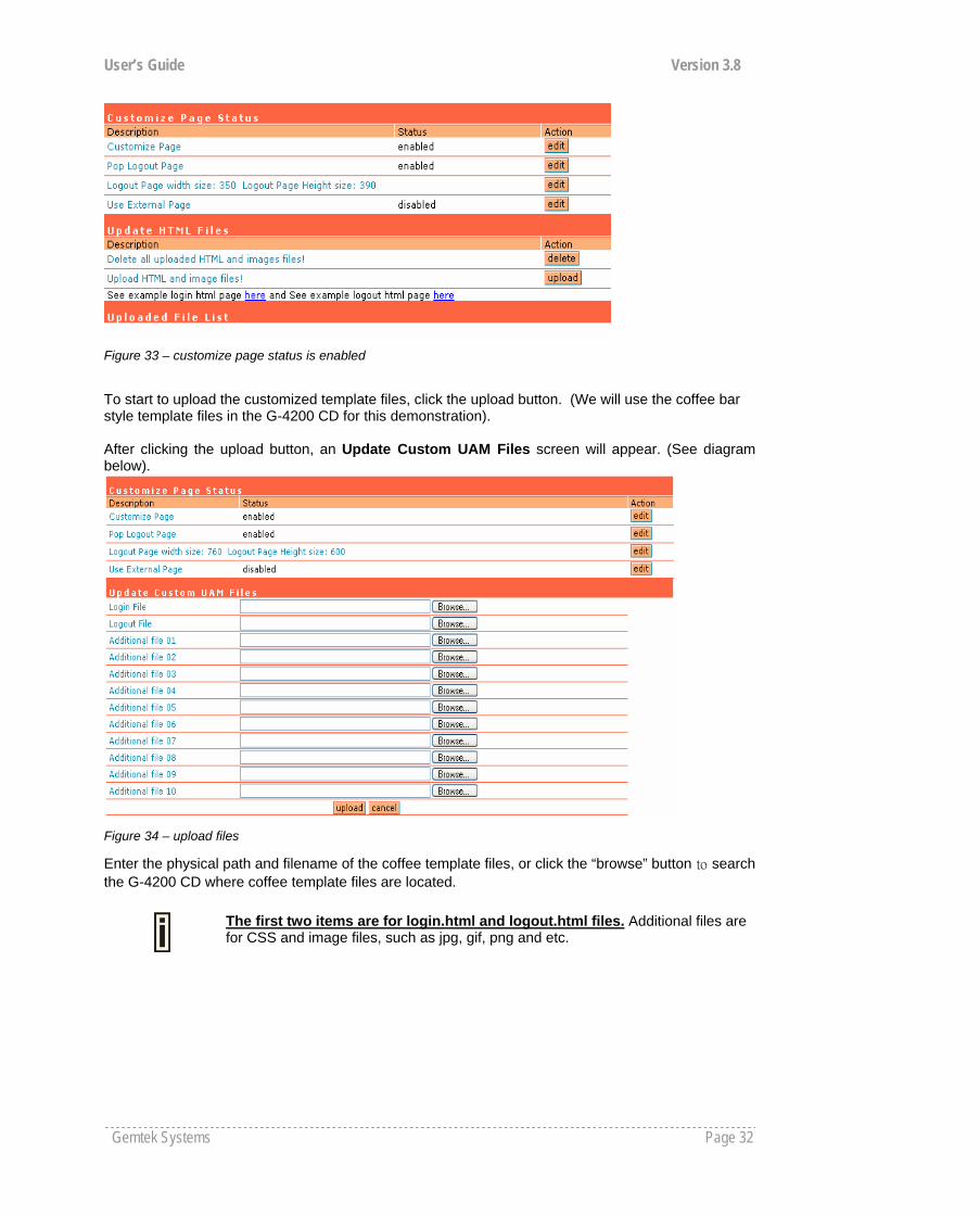
Figure 33 – customize page status is enabled
To start to upload the customized template files, click the upload button. (We will use the coffee bar style template files in the G-4200 CD for this demonstration). After clicking the upload button, an Update Custom UAM Files screen will appear. (See diagram below).
Figure 34 – upload files
Enter the physical path and filename of the coffee template files, or click the “browse” button to search the G-4200 CD where coffee template files are located.
The first two items are for login.html and logout.html files. Additional files are for CSS and image files, such as jpg, gif, png and etc.

User’s Guide Version 3.8
Gemtek Systems Page 33
Figure 35 – select example files
Figure 36 – upload login.html
After entering all the template files, press upload button to start the uploading files to G-4200.
Only ten Additional files can be uploaded at one time. To upload more additional file, repeat the same upload process in step 2-4, but please be aware of the first two items are only for login.html and logout.html files. Image files can only be uploaded to Additional file fields

User’s Guide Version 3.8
Gemtek Systems Page 34
Figure 37 – upload other files
Once all files are uploaded successfully, a list of Uploaded File List will show.
Figure 38 – files have been uploaded
Verify if all files are uploaded successfully
User’s Guide Version 3.8
Gemtek Systems Page 35
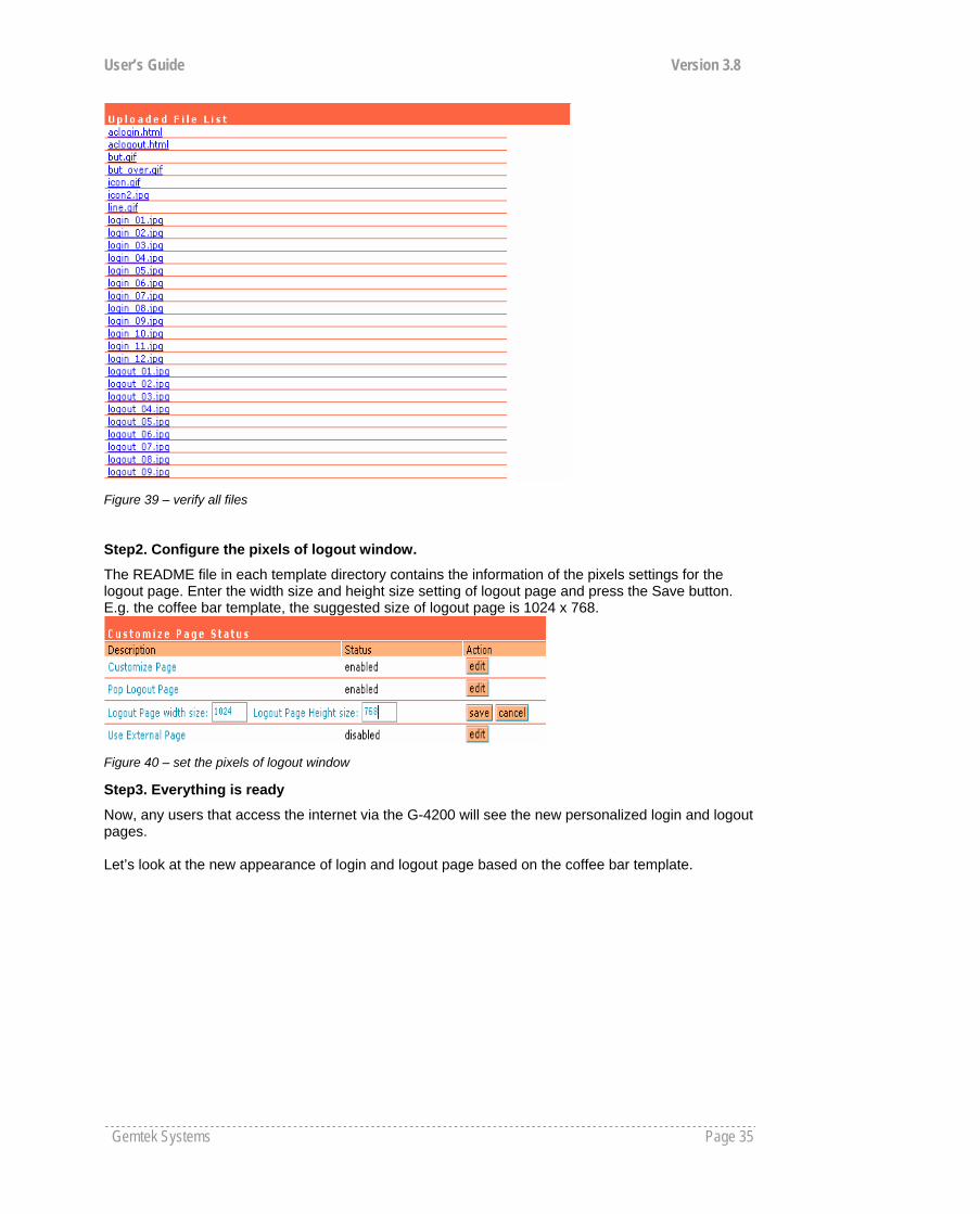
Figure 39 – verify all files
Step2. Configure the pixels of logout window.
The README file in each template directory contains the information of the pixels settings for the logout page. Enter the width size and height size setting of logout page and press the Save button. E.g. the coffee bar template, the suggested size of logout page is 1024 x 768.
Figure 40 – set the pixels of logout window
Step3. Everything is ready
Now, any users that access the internet via the G-4200 will see the new personalized login and logout pages. Let’s look at the new appearance of login and logout page based on the coffee bar template.

User’s Guide Version 3.8
Gemtek Systems Page 36
:
Figure 41 – example of coffee bar login page
Figure 42 – example of coffee bar logout page
FAQ 1. Question: How to add some links that could be accessed without authentication?
Answer: These authentication-free sites for users are so called “walled garden ”area. Please refer to the user’s guide to do the relating settings.
User’s Guide Version 3.8
Gemtek Systems Page 37
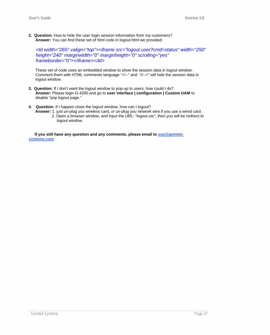
2. Question: How to hide the user login session information from my customers?
Answer: You can find these set of html code in logout.html we provided:
<td width="265" valign="top"><iframe src="logout.user?cmd=status" width="250" height="240" marginwidth="0" marginheight="0" scrolling="yes" frameborder="0"></iframe></td>
These set of code uses an embedded window to show the session data in logout window. Comment them with HTML comments language “<!--“ and “//-->” will hide the session data in logout window.
3. Question: If I don’t want the logout window to pop-up to users, how could I do?
Answer: Please login G-4200 and go to user interface | configuration | Custom UAM to disable “pop logout page.”
4. Question: If I happen close the logout window, how can I logout? Answer: 1. just un-plug you wireless card, or un-plug you network wire if you use a wired card. 2. Open a browser window, and input the URL: “logout.usr”, then you will be redirect to logout window.
If you still have any question and any comments, please email to [email protected]
User’s Guide Version 3.8
Gemtek Systems Page 38
Introduction The CLI (Command Line Interface) software is a configuration shell for the Access Controller. Using the CLI system operator can configure:
User interface Network interface Wireless interface System
Using the CLI system operator can check:
Status (device, network, service) Connection
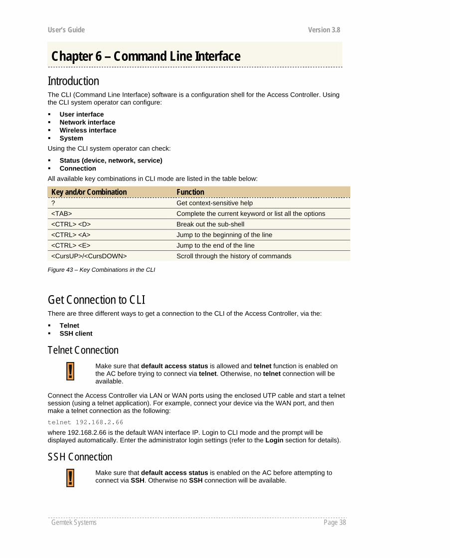
All available key combinations in CLI mode are listed in the table below:
Key and/or Combination Function ? Get context-sensitive help <TAB> Complete the current keyword or list all the options <CTRL> <D> Break out the sub-shell <CTRL> <A> Jump to the beginning of the line <CTRL> <E> Jump to the end of the line <CursUP>/<CursDOWN> Scroll through the history of commands
Figure 43 – Key Combinations in the CLI
Get Connection to CLI There are three different ways to get a connection to the CLI of the Access Controller, via the:
Telnet SSH client
Telnet Connection
Connect the Access Controller via LAN or WAN ports using the enclosed UTP cable and start a telnet session (using a telnet application). For example, connect your device via the WAN port, and then make a telnet connection as the following:
telnet 192.168.2.66
where 192.168.2.66 is the default WAN interface IP. Login to CLI mode and the prompt will be displayed automatically. Enter the administrator login settings (refer to the Login section for details).
SSH Connection
Chapter 6 – Command Line Interface
Make sure that default access status is allowed and telnet function is enabled on the AC before trying to connect via telnet. Otherwise, no telnet connection will be available.
Make sure that default access status is enabled on the AC before attempting to connect via SSH. Otherwise no SSH connection will be available.
User’s Guide Version 3.8
Gemtek Systems Page 39
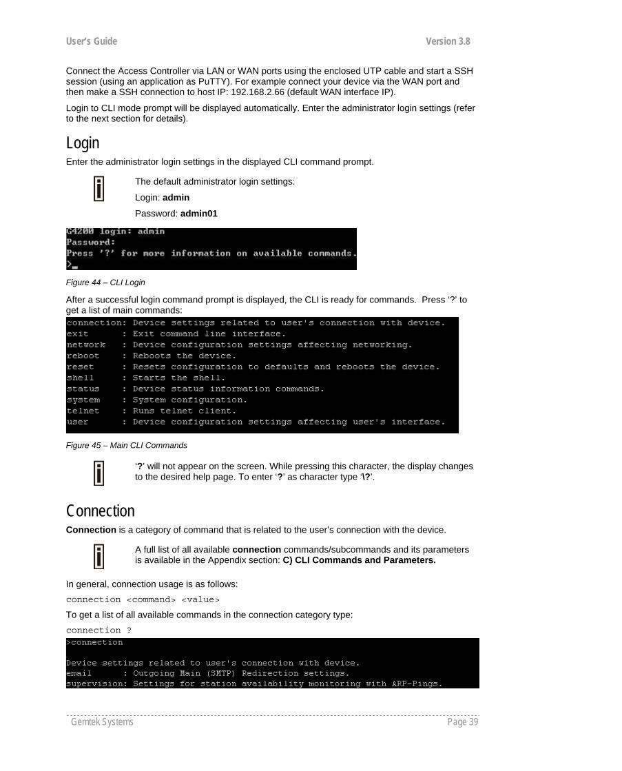
Connect the Access Controller via LAN or WAN ports using the enclosed UTP cable and start a SSH session (using an application as PuTTY). For example connect your device via the WAN port and then make a SSH connection to host IP: 192.168.2.66 (default WAN interface IP).
Login to CLI mode prompt will be displayed automatically. Enter the administrator login settings (refer to the next section for details).
Login Enter the administrator login settings in the displayed CLI command prompt.
The default administrator login settings:
Login: admin
Password: admin01
Figure 44 – CLI Login
After a successful login command prompt is displayed, the CLI is ready for commands. Press ‘?’ to get a list of main commands:
Figure 45 – Main CLI Commands
‘?’ will not appear on the screen. While pressing this character, the display changes to the desired help page. To enter ‘?’ as character type ‘\?’.
Connection Connection is a category of command that is related to the user’s connection with the device.
A full list of all available connection commands/subcommands and its parameters is available in the Appendix section: C) CLI Commands and Parameters.
In general, connection usage is as follows: connection <command> <value>
To get a list of all available commands in the connection category type: connection ?
User’s Guide Version 3.8
Gemtek Systems Page 40
Figure 46 – Connection Commands
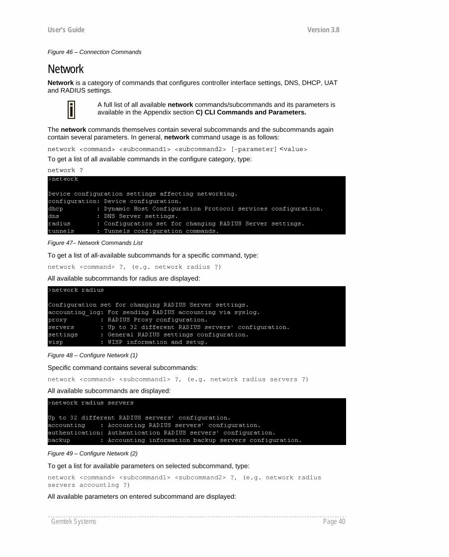
Network Network is a category of commands that configures controller interface settings, DNS, DHCP, UAT and RADIUS settings.
A full list of all available network commands/subcommands and its parameters is available in the Appendix section C) CLI Commands and Parameters.
The network commands themselves contain several subcommands and the subcommands again contain several parameters. In general, network command usage is as follows:
network <command> <subcommand1> <subcommand2> [-parameter] <value> To get a list of all available commands in the configure category, type: network ?
Figure 47– Network Commands List
To get a list of all-available subcommands for a specific command, type:
network <command> ?, (e.g. network radius ?)
All available subcommands for radius are displayed:
Figure 48 – Configure Network (1)
Specific command contains several subcommands:
network <command> <subcommand1> ?, (e.g. network radius servers ?)
All available subcommands are displayed:
Figure 49 – Configure Network (2)
To get a list for available parameters on selected subcommand, type:
network <command> <subcommand1> <subcommand2> ?, (e.g. network radius servers accounting ?)
All available parameters on entered subcommand are displayed:

User’s Guide Version 3.8
Gemtek Systems Page 41
Figure 50 – Configure Network (3)
To configure the desired controller interface setting, type all required parameters with values and subcommands:
network <command> <subcommand1> <subcommand2> [-parameter] <value>
(e.g. network radius servers accounting 1 –a 127.0.0.2 –p 1814 –s testing111), where parameters are as follows:
-a – RADIUS server IP address used for RADIUS accounting
-p – RADIUS server port number used for RADIUS accounting
-s – Shared secret key for accounting.
Figure 51 – Configure Network (4)
If successful, a message regarding the successful completion is displayed; otherwise, an error message is displayed.
In some cases, entered commands without parameters display current controller configuration or settings:
network <command> <subcommad1> <subcommad2>, (e.g. radius servers accounting), displays available RADIUS servers and its settings list (in this case, the RADIUS accounting server which is already updated):
Figure 52 – Configure Network (5)
User’s Guide Version 3.8
Gemtek Systems Page 42
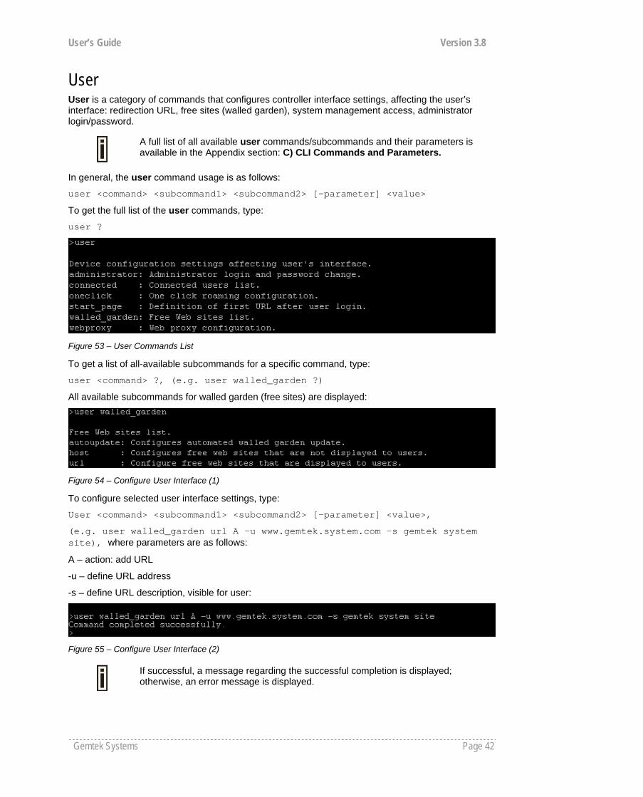
User User is a category of commands that configures controller interface settings, affecting the user’s interface: redirection URL, free sites (walled garden), system management access, administrator login/password.
A full list of all available user commands/subcommands and their parameters is available in the Appendix section: C) CLI Commands and Parameters.
In general, the user command usage is as follows:
user <command> <subcommand1> <subcommand2> [-parameter] <value>
To get the full list of the user commands, type:
user ?
Figure 53 – User Commands List
To get a list of all-available subcommands for a specific command, type:
user <command> ?, (e.g. user walled_garden ?)
All available subcommands for walled garden (free sites) are displayed:
Figure 54 – Configure User Interface (1)
To configure selected user interface settings, type:
User <command> <subcommand1> <subcommand2> [-parameter] <value>,
(e.g. user walled_garden url A -u www.gemtek.system.com -s gemtek system site), where parameters are as follows:
A – action: add URL
-u – define URL address
-s – define URL description, visible for user:
Figure 55 – Configure User Interface (2)
If successful, a message regarding the successful completion is displayed; otherwise, an error message is displayed.

User’s Guide Version 3.8
Gemtek Systems Page 43
Status Status is a category of commands that’s displays:
General devices status (model, firmware version, uptime, memory) All interface network settings (IP address/netmask, MAC address, gateway, RX/TX statistics) Currently running services (DHCP, routes, port forward, telnet, SNMP, UAT, ..).
A full list of all available status commands/subcommands and their parameters is available in the Appendix section: C) CLI Commands and Parameters.
In general the status command usage is as follows:
Status <command>
To get the full list of the status commands, type:
status ?
Figure 56 – System Status Commands List
To get the general device status information, type:
status device :
Figure 57 – Device Status
Here you can find the current firmware version of your AC. This is important information for support requests and for preparing firmware uploads.
System System is a category of commands that configures access to controller (telnet, AAA methods, L2 isolation, SNMP, UAT) and configuration: clock, NTP, syslog, trace.
A list of all available system commands/subcommands and their parameters are available in the Appendix section: C) CLI Commands and Parameters.
In general, the system command usage is as follows:
system <command> <subcommand1> <subcommand2> [-parameter] <value>
User’s Guide Version 3.8
Gemtek Systems Page 44
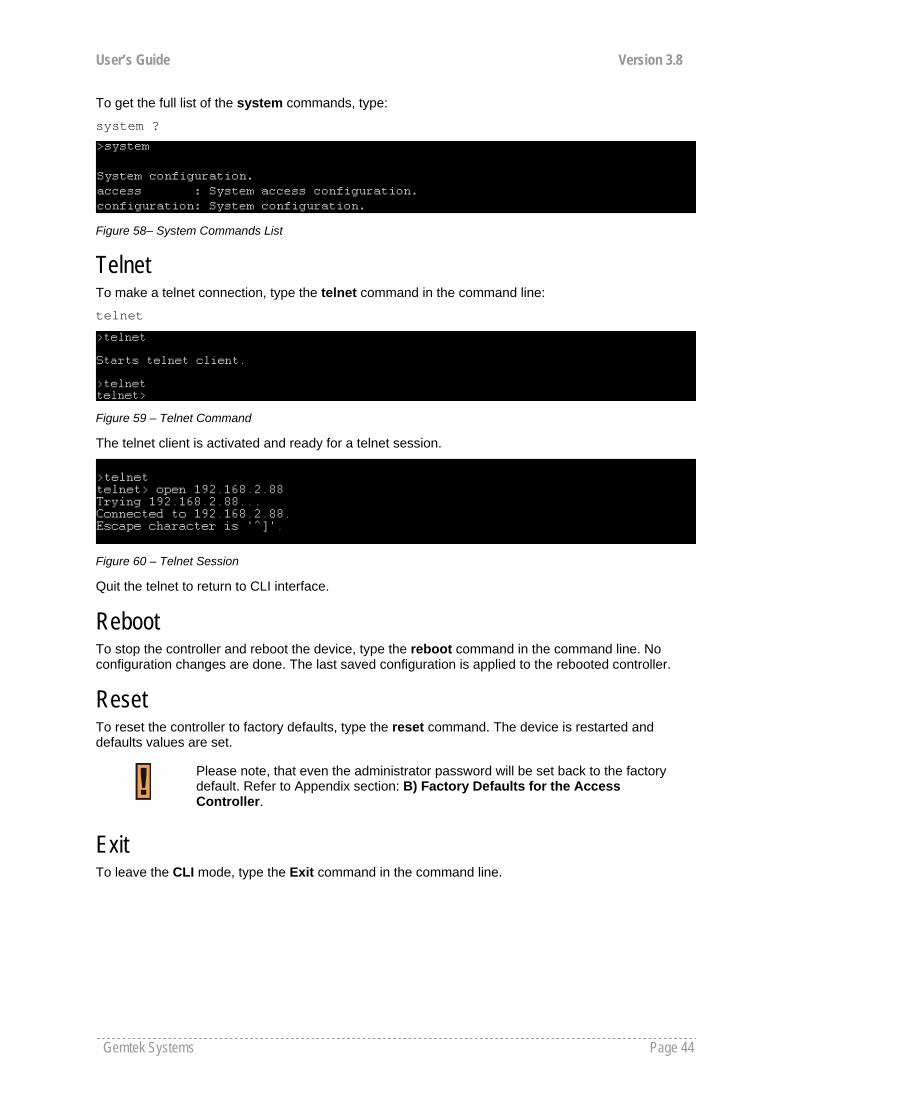
To get the full list of the system commands, type:
system ?
Figure 58– System Commands List
Telnet To make a telnet connection, type the telnet command in the command line:
telnet
Figure 59 – Telnet Command
The telnet client is activated and ready for a telnet session.
Figure 60 – Telnet Session
Quit the telnet to return to CLI interface.
Reboot To stop the controller and reboot the device, type the reboot command in the command line. No configuration changes are done. The last saved configuration is applied to the rebooted controller.
Reset To reset the controller to factory defaults, type the reset command. The device is restarted and defaults values are set.
Please note, that even the administrator password will be set back to the factory default. Refer to Appendix section: B) Factory Defaults for the Access Controller.
Exit To leave the CLI mode, type the Exit command in the command line.
User’s Guide Version 3.8
Gemtek Systems Page 45
Introduction Another way to configure and monitor the Access Controller (G-4200) via a TCP/IP network is SNMP (Simple Network Management Protocol).
SNMP is an application layer protocol that facilitates the exchange of management information between network devices. It is part of the Transmission Control Protocol/Internet Protocol (TCP/IP) protocol suite. SNMP enables network administrators to manage network performance, find and solve network problems, and plan for network growth.
The SNMP agent and management information base (MIB) reside on the Access Controller. To configure SNMP on the controller, you define the relationship between the Network Management System (NMS) and the SNMP agent (our AC). The SNMP agent contains MIB and Gemtek Systems private MIB variables whose values the SNMP manager can request or change. A NMS can get a value from an agent or store a value into the agent. The agent gathers data from the MIB, the repository for information about device parameters and network data. The agent can also respond to a manager’s requests to get or set data.
In order to manage the device you have to provide your Network Management System software with adequate MIB files. Please consult your management software manuals on how to do that.
SNMP Versions Access Controller supports the following versions of SNMP:
SNMPv1—The Simple Network Management Protocol: A Full Internet Standard, defined in RFC 1157. (RFC 1157 replaces the earlier versions that were published as RFC 1067 and RFC 1098.) Security is based on community strings.
SNMPv2c—The community-string based Administrative Framework for SNMPv2. SNMPv2c (the "C" stands for "community") is an Experimental Internet Protocol defined in RFC 1901, RFC 1905, and RFC 1906. SNMPv2c is an update of the protocol operations and data types of SNMPv2p (SNMPv2 Classic), and uses the community-based security model of SNMPv1.
SNMPv3 – SNMP v3 is based on version 2 with added security features. It addresses security
requirements through encryption, authentication, and access control rules.
Both SNMPv1 and SNMPv2c use a community-based form of security. The community of managers able to access the agent's MIB is defined by an IP address access control list and password.
The Access Controller implementation of SNMP supports all MIB II variables (as described in RFC 1213) and defines all traps using the guidelines described in RFC 1215.The traps described in this RFC are:
coldStart
A coldStart trap signifies that the SNMP entity, acting in an agent role, is reinitializing itself and that its configuration may have been altered.
WarmStart
A WarmStart trap signifies that the SNMP entity, acting in an agent role, is reinitializing itself
Chapter 7 – SNMP Management
User’s Guide Version 3.8
Gemtek Systems Page 46
and that its configuration is unaltered. authenticationFailure
An authenticationFailure trap signifies that the SNMP entity, acting in an agent role, has received a protocol message that is not properly authenticated.
linkDown
A linkDown trap signifies that the SNMP entity, acting in an agent role, recognizes a failure in one of the communication links represented in the agent's configuration.
linkUp
A linkUp trap signifies that the SNMP entity, acting in an agent role, recognizes that one of the communication links represented in the agent's configuration has come up.
SNMP Agent The SNMP agent responds to SNMP manager requests as follows:
Get a MIB variable—The SNMP agent begins this function in response to a request from the SNMP manager. The agent retrieves the value of the requested MIB variable and responds to the manager with that value.
Set a MIB variable—The SNMP agent begins this function in response to a message from the SNMP manager. The SNMP agent changes the value of the MIB variable to the value requested by the manager.
The SNMP agent also sends unsolicited trap messages to notify an SNMP manager that a significant event has occurred (e.g. authentication failures) on the agent.
SNMP Community Strings SNMP community strings authenticate access to MIB objects and function as embedded passwords. In order for the SNMP manager to access the controller, the community string must match one of the two community string definitions on the controller. A community string can be as follows:
Read-only—Gives read access to authorized management stations to all objects in the MIB except the community strings, but does not allow write access.
Read-write—Gives read and write access to authorized management stations to all objects in the MIB, but does not allow access to the community strings.
User’s Guide Version 3.8
Gemtek Systems Page 47
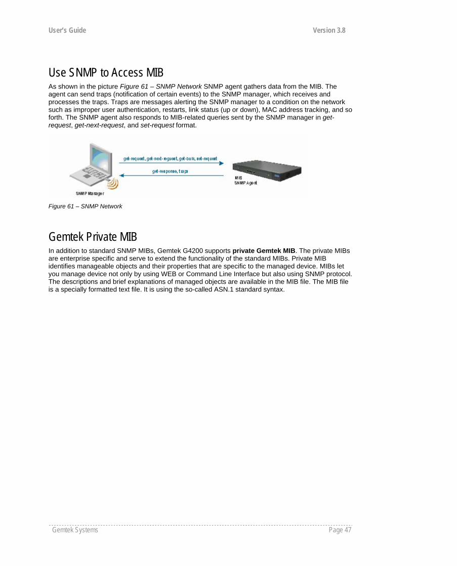
Use SNMP to Access MIB As shown in the picture Figure 61 – SNMP Network SNMP agent gathers data from the MIB. The agent can send traps (notification of certain events) to the SNMP manager, which receives and processes the traps. Traps are messages alerting the SNMP manager to a condition on the network such as improper user authentication, restarts, link status (up or down), MAC address tracking, and so forth. The SNMP agent also responds to MIB-related queries sent by the SNMP manager in get-request, get-next-request, and set-request format.
Figure 61 – SNMP Network
Gemtek Private MIB In addition to standard SNMP MIBs, Gemtek G4200 supports private Gemtek MIB. The private MIBs are enterprise specific and serve to extend the functionality of the standard MIBs. Private MIB identifies manageable objects and their properties that are specific to the managed device. MIBs let you manage device not only by using WEB or Command Line Interface but also using SNMP protocol. The descriptions and brief explanations of managed objects are available in the MIB file. The MIB file is a specially formatted text file. It is using the so-called ASN.1 standard syntax.

User’s Guide Version 3.8
Gemtek Systems Page 48
This chapter contains Hotspot-in-a-Box web management reference information.
The web management main menu consists of the following sub menus:
Network Interface – device configuration settings affecting networking. User Interface – device configuration settings affecting the user interface. System – device system configuration settings directly applicable to the controller. Connection– device settings related to user’s connection with the G-4200. Built-In AAA – Built-in AAA system for web authentication and accounting. Exit – click exit and leave the web management then close your web-browser window.
Web Interface The main web management menu is displayed at the top of the page after successfully logging into the system (see the figure below). From this menu all essential configuration pages are accessed.
Figure 62 – Main Configuration Management Menu
By default the system | status menu is activated and the current AC system status is displayed. The active menu is displayed in a different color.
The web management menu has the following structure:
Network Interface
Configuration – configuration page for all controller network interfaces Interface configuration – network interfaces configuration VLAN – define VLAN on your controller Route – define new static route on the controller interface Port forwarding – port-forwarding rules DHCP Relay – DHCP relay server configuration User ACL – define packet filter rules Management subnet – access points (APs) management
DNS – define DNS server settings DHCP – Dynamic Host Configuration Protocol services configuration RADIUS – configuration set for RADIUS servers, includes menu:
RADIUS settings – NAS server ID, hotspot operator name and other settings RADIUS servers – accounting, authentication RADIUS servers IP, port and other settings WISP – add new WISP on the system. Proxy – configure the AC to act as RADIUS server proxy. Accounting backup – backup authentication logs in the remote or external server
Tunnels – set tunnels: PPPoE/ GRE for DSL – connect to ISP via the PPPoE or GRE tunnel GRE Client for VPN – set the GRE (Generic Routing Encapsulation) tunnels for the G-4200
User Interface
Configuration –Welcome/Login/Logout/Help page customization Pages – configure and upload user pages Upload – upload new internal user pages Headers – define http headers encoding and language Custom Uam – customized user login and logout page based by HTML page.
Administrator – administrator login and password change
Chapter 8 – Reference Manual
User’s Guide Version 3.8
Gemtek Systems Page 49
Start page – define start page URL Walled Garden – free web site list Web Proxy – web proxy settings for clients
System
Configuration – system configuration utilities: Syslog – specify address where to send system log file Trace system – trace such controller services as PPPoE ( will not appear on main menu, use URL: https://G-4200-ip/nas_tracesystem.rg to access directly ) Clock – system clock settings NTP – get time from network time protocol service Certificate– upload new certificates into the local controller memory Save and restore – save current device configuration for backup Domain Name – Configure G-4200 domain for uniform digital certificate. Share Username - setting user account shared status
Access – configure access to your controller: Access Control – set default access to your AC Telnet – enable/disable telnet connections AAA – define different AAA methods UAT – enable/disable universal address translation Isolation – restricts clients from communicating along Level 2 separation NAV – NAT, authentication and visitor access control SNMP – SNMP service and proxies Web Auth – Settings for auth methods of Built-in AAA MAC List -MAC ACL table. HTTPC -Configure if client use HTTPS or HTTP for web authentication.
Status – AC system status Reset – reset configuration to factory defaults values and/or reboot Update – find out current software version and update with new firmware
Connection
Users – connected users’ statistics list and log-out user function E-Mail Redirection – outgoing mail (SMTP) redirection settings Station Supervision – monitor station availability with ARP-pings settings
Built-in AAA
E-Billing – Post paid built-in AAA system User Control – management E-Billing (Built-in AAA) user account. Band Class – band width management for E-Billing account. Bill setting – configure the billing policy and price for E-Billing account Power cut protection – setting for power off protection
Pre-paid – per-paid built-in AAA system User Account – show current generated pre-paid account Price/unit – setting of price and unit Account life – setting of receipts available life Web Key and SSID – setting Web key and SSID printed on receipts Receipts – history of printed receipts and profit Account reminder – remind hot spot owner checking the income of prepaid account.
Configuration - Billing Backup and restore; Receipt Language and title configuration. Language – setting language of printed receipts Backup and Restore – Backup and restore Built-in AAA account and billing records. Title – setting of venue name
In the following sections, short references for all menu items are presented.
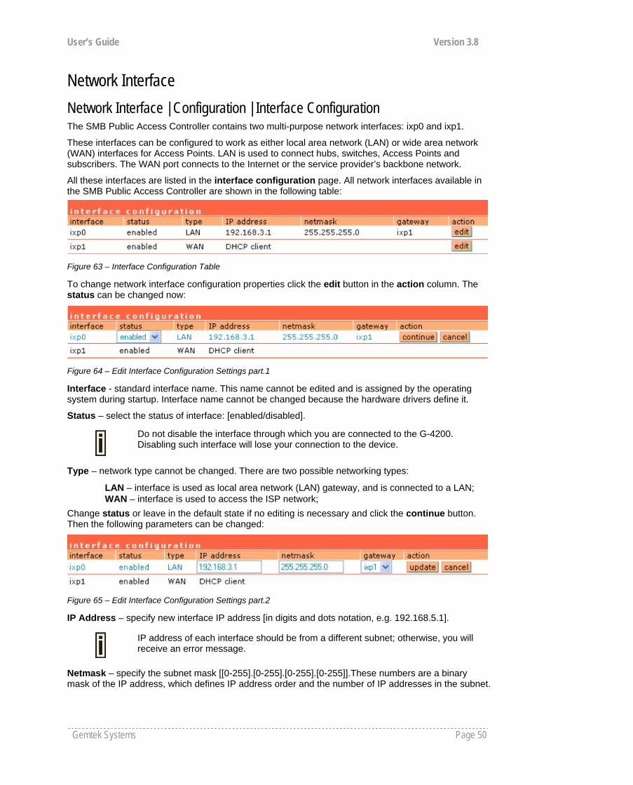
User’s Guide Version 3.8
Gemtek Systems Page 50
Network Interface Network Interface | Configuration | Interface Configuration The SMB Public Access Controller contains two multi-purpose network interfaces: ixp0 and ixp1.
These interfaces can be configured to work as either local area network (LAN) or wide area network (WAN) interfaces for Access Points. LAN is used to connect hubs, switches, Access Points and subscribers. The WAN port connects to the Internet or the service provider’s backbone network.
All these interfaces are listed in the interface configuration page. All network interfaces available in the SMB Public Access Controller are shown in the following table:
Figure 63 – Interface Configuration Table
To change network interface configuration properties click the edit button in the action column. The status can be changed now:
Figure 64 – Edit Interface Configuration Settings part.1
Interface - standard interface name. This name cannot be edited and is assigned by the operating system during startup. Interface name cannot be changed because the hardware drivers define it.
Status – select the status of interface: [enabled/disabled].
Do not disable the interface through which you are connected to the G-4200. Disabling such interface will lose your connection to the device.
Type – network type cannot be changed. There are two possible networking types:
LAN – interface is used as local area network (LAN) gateway, and is connected to a LAN; WAN – interface is used to access the ISP network;
Change status or leave in the default state if no editing is necessary and click the continue button. Then the following parameters can be changed:
Figure 65 – Edit Interface Configuration Settings part.2
IP Address – specify new interface IP address [in digits and dots notation, e.g. 192.168.5.1].
IP address of each interface should be from a different subnet; otherwise, you will receive an error message.
Netmask – specify the subnet mask [[0-255].[0-255].[0-255].[0-255]].These numbers are a binary mask of the IP address, which defines IP address order and the number of IP addresses in the subnet.

User’s Guide Version 3.8
Gemtek Systems Page 51
Gateway – interface gateway. For LAN type interfaces, the gateway can only be defined as WAN interface gateway. The gateway of the WAN interface is usually the gateway router of the ISP or other WAN network. [Default gateway is marked with ‘*’].
Update – update old values with entered ones.
The DHCP server settings will be automatically adjusted to match the new network settings.
Figure 66 – Apply or Discard Interface Configuration Changes
Apply changes – to save all changes made in the interface configuration table at once.
Discard changes – restore all previous values.
For such general changes as interface settings change, the Hotspot-in-a-Box server needs to be restarted. Request for restart server appears:
Figure 67 – Restart Server
Restart – Click the button to restart the server and apply the changes.
Network Interface | Configuration | VLAN
Up to 4094 VLANs can be created in the system.
Virtual Local Area Networks (VLANs) are logical groupings of network resources. You can create your own VLANs on your AC using the network interface | configuration | VLAN menu. By default no VLANS are defined on the system:
Figure 68 – VLAN
To create a VLAN on the AC click the new button and enter following parameters:
Figure 69 – Create New VLAN

User’s Guide Version 3.8
Gemtek Systems Page 52
Interface – select interface for your VLAN network [ixp0]. Cannot create VLAN on the bridge.
Status – non-editable, by default is disabled.
ID – assign ID for your VLAN network [1 to 4094]. Client devices that associate using the ID are grouped into this VLAN.
Other VLAN settings cannot be changed. Click on the disabled link to continue specifying settings for your VLAN. The network interface configuration page is opened and VLAN settings are ready for editing:
Figure 70 – Configure VLAN
Status – enable/disable your VLAN network. Select [enable] and click the continue button to configure the VLAN settings:
Figure 71 – Configure VLAN
Type – cannot be edited, depends on selected interface for VLAN [ixp0].
IP Address – enter the network address of your VLAN [format: digits and dots].
Netmask – enter the netmask for your VLAN network [format: digits and dots].
Gateway – select gateway for VLAN network [default: ixp1].
Click the update and restart and apply changes to save your new VLAN. Check the interface | configuration | VLAN menu for new created VLAN:
Figure 72 – Enable New VLAN
Network Interface | Configuration | Route Under the network interface | configuration | route menu, static routes for the Ethernet interfaces can be set. By default no static routes are defined on the system:
Figure 73 – Route
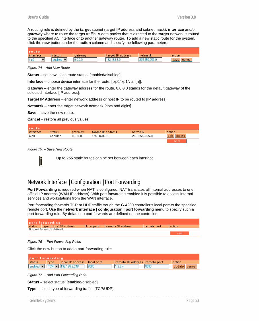
User’s Guide Version 3.8
Gemtek Systems Page 53
A routing rule is defined by the target subnet (target IP address and subnet mask), interface and/or gateway where to route the target traffic. A data packet that is directed to the target network is routed to the specified AC interface or to another gateway router. To add a new static route for the system, click the new button under the action column and specify the following parameters:
Figure 74 – Add New Route
Status – set new static route status: [enabled/disabled].
Interface – choose device interface for the route: [ixp0/ixp1/vlan[n]].
Gateway – enter the gateway address for the route. 0.0.0.0 stands for the default gateway of the selected interface [IP address].
Target IP Address – enter network address or host IP to be routed to [IP address].
Netmask – enter the target network netmask [dots and digits].
Save – save the new route.
Cancel – restore all previous values.
Figure 75 – Save New Route
Up to 255 static routes can be set between each interface.
Network Interface | Configuration | Port Forwarding Port Forwarding is required when NAT is configured. NAT translates all internal addresses to one official IP address (WAN IP address). With port forwarding enabled it is possible to access internal services and workstations from the WAN interface.
Port forwarding forwards TCP or UDP traffic trough the G-4200 controller’s local port to the specified remote port. Use the network interface | configuration | port forwarding menu to specify such a port forwarding rule. By default no port forwards are defined on the controller:
Figure 76 – Port Forwarding Rules
Click the new button to add a port-forwarding rule:
Figure 77 – Add Port Forwarding Rule.
Status – select status: [enabled/disabled].
Type – select type of forwarding traffic: [TCP/UDP].
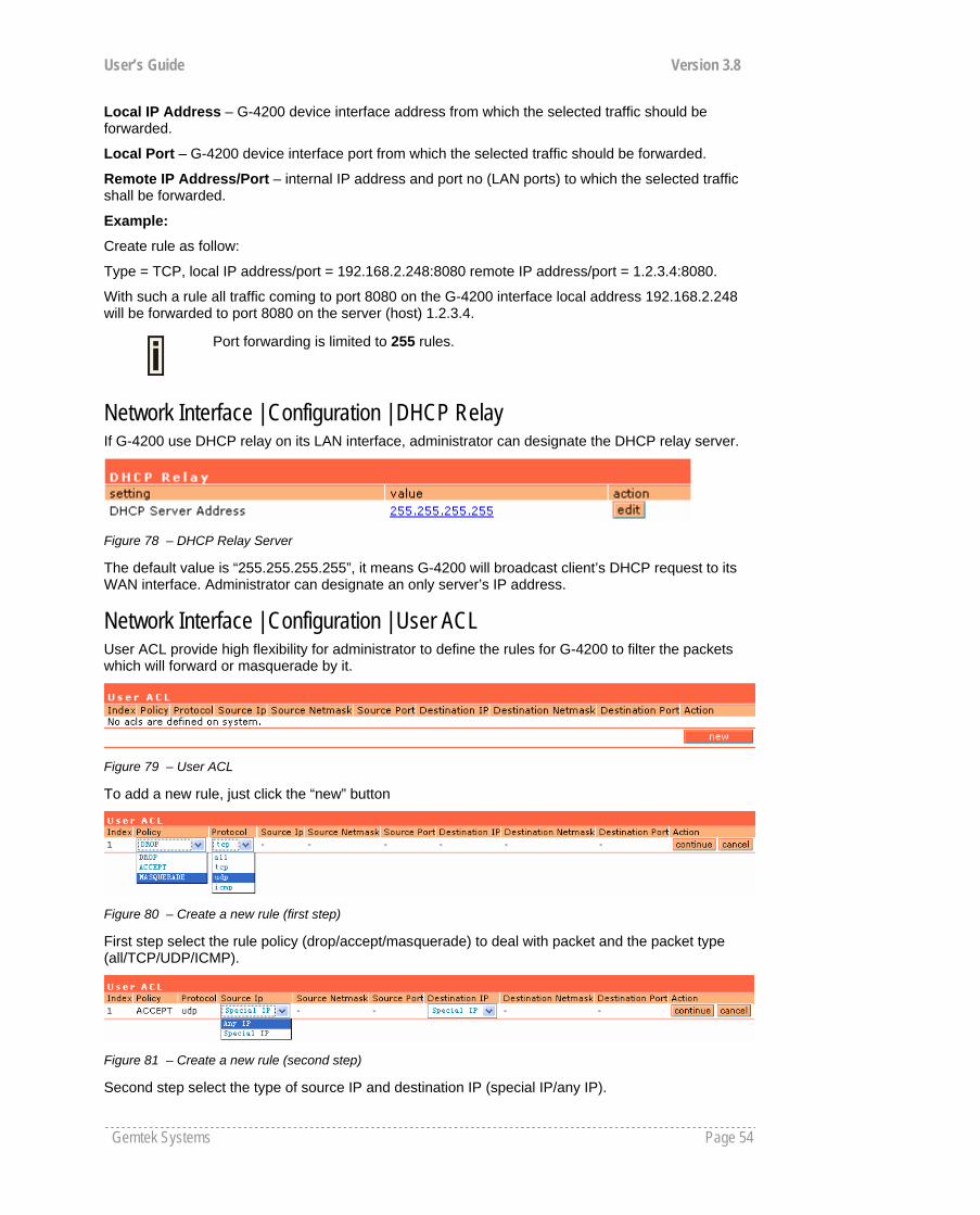
User’s Guide Version 3.8
Gemtek Systems Page 54
Local IP Address – G-4200 device interface address from which the selected traffic should be forwarded.
Local Port – G-4200 device interface port from which the selected traffic should be forwarded.
Remote IP Address/Port – internal IP address and port no (LAN ports) to which the selected traffic shall be forwarded.
Example:
Create rule as follow:
Type = TCP, local IP address/port = 192.168.2.248:8080 remote IP address/port = 1.2.3.4:8080.
With such a rule all traffic coming to port 8080 on the G-4200 interface local address 192.168.2.248 will be forwarded to port 8080 on the server (host) 1.2.3.4.
Port forwarding is limited to 255 rules.
Network Interface | Configuration | DHCP Relay If G-4200 use DHCP relay on its LAN interface, administrator can designate the DHCP relay server.
Figure 78 – DHCP Relay Server
The default value is “255.255.255.255”, it means G-4200 will broadcast client’s DHCP request to its WAN interface. Administrator can designate an only server’s IP address.
Network Interface | Configuration | User ACL User ACL provide high flexibility for administrator to define the rules for G-4200 to filter the packets which will forward or masquerade by it.
Figure 79 – User ACL
To add a new rule, just click the “new” button
Figure 80 – Create a new rule (first step)
First step select the rule policy (drop/accept/masquerade) to deal with packet and the packet type (all/TCP/UDP/ICMP).
Figure 81 – Create a new rule (second step)
Second step select the type of source IP and destination IP (special IP/any IP).
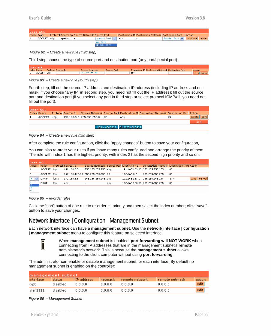
User’s Guide Version 3.8
Gemtek Systems Page 55
Figure 82 – Create a new rule (third step)
Third step choose the type of source port and destination port (any port/special port).
Figure 83 – Create a new rule (fourth step)
Fourth step, fill out the source IP address and destination IP address (including IP address and net mask, if you choose “any IP” in second step, you need not fill out the IP address); fill out the source port and destination port (if you select any port in third step or select protocol ICMP/all, you need not fill out the port).
Figure 84 – Create a new rule (fifth step)
After complete the rule configuration, click the “apply changes” button to save your configuration,
You can also re-order your rules if you have many rules configured and arrange the priority of them. The rule with index 1 has the highest priority; with index 2 has the second high priority and so on.
Figure 85 – re-order rules
Click the “sort” button of one rule to re-order its priority and then select the index number; click “save” button to save your changes.
Network Interface | Configuration | Management Subnet Each network interface can have a management subnet. Use the network interface | configuration | management subnet menu to configure this feature on selected interface.
When management subnet is enabled, port forwarding will NOT WORK when connecting from IP addresses that are in the management subnet's remote administrator's network. This is because the management subnet allows connecting to the client computer without using port forwarding.
The administrator can enable or disable management subnet for each interface. By default no management subnet is enabled on the controller:
Figure 86 – Management Subnet

User’s Guide Version 3.8
Gemtek Systems Page 56
To specify new subnet management click the edit button on the selected interface:
Figure 87 – Add Management Subnet
IP Address and Netmask – specify the IP address and netmask of the management subnet. IP address will be set on the network interface as an alias, so you can connect to the G-4200 using this address. This IP address should be used on access points as the gateway address.
Remote Network and Netmask –specify the remote network that is allowed to access the local management subnet. Only addresses that are from the remote network will be accepted [dots and digits].
If you do not specify any remote network all stations with IP addresses from the management LAN are routed to the WAN port even without being authenticated.
Clients using an IP address from the management subnet can browse the Internet without authorization, and no accounting will be done. Thus, it is strongly recommended to allow traffic only from the administrative remote network (no 0.0.0.0/0.0.0.0 in remote specification).
Example:
Interface configuration for ixp0:
type: LAN IP address: 192.168.3.1 netmask: 255.255.255.0 gateway: ixp1
Management subnet on ixp0:
IP address: 10.0.0.1 netmask: 255.255.255.0 remote network: 10.10.0.1 remote netmask: 255.255.255.0
With these settings applied, the administrator will be able to connect to devices behind the G-4200 on interface ixp0, if these devices use address in the range: 10.0.0.2 ... 10.0.0.254. The administrator is connecting via the Internet (from ixp1 interface).
The administrator’s computer can have an address from 10.10.0.1 to 10.10.0.254.
Please note that devices which are using 10.0.0.2. – 10.0.0.254 addresses have access to the administrative network too!
In this example, the administrative network uses the reserved IP address (10.x.x.x) – they are not routed in the Internet, so the administrator should setup routers in a path between the G-4200 and the administrator's computer to recognize 10.x.x.x addresses and route them correctly. This is not comfortable and sometimes it is impossible. There is a solution – the administrator can use GRE tunnel(see: Network Interface | Tunnels) to setup a tunnel between the administrator's computer and the G-4200. The only addresses visible on the Internet will be the G-4200 WAN IP address and the administrator's computer (or router) IP address.
Network Interface | DNS DNS (Domain Name Service) service allows AC subscribers to enter URLs instead of IP addresses into their browser to reach the desired web site.

User’s Guide Version 3.8
Gemtek Systems Page 57
Figure 88 –- DNS Settings Configuration
You can enter the primary and secondary DNS servers settings under the network interface | DNS menu:
Figure 89 – DNS Redirection Settings
The DNS server or DNS address can be obtained dynamically if DHCP, PPPoE (for DSL) service is enabled. To add DNS server manually click the edit button in the action column and type in the DNS server’s IP address:
Figure 90 – Edit DNS Redirection Settings
IP address – enter the primary or secondary DNS server’s IP address [in digits and dots notation].
Save – click to save the new DNS server’s settings.
Network Interface | DHCP The G-4200 controller can act as a DHCP server and/or as a DHCP relay gateway. The DHCP (Dynamic Host Configuration Protocol) service is supported on the LAN interfaces [ixp0/vlan[n]]. This service enables clients on the LAN to request configuration information, such as an IP address, from a server. This service can be viewed in the following table:
Figure 91 – DHCP Configuration
By default the AC is configured to act as a DHCP server.
Each LAN interface runs a different instance of the DHCP service. This service is configured by defining an IP address range and WINS address for client workstations. Other settings, such as the default gateway and DNS server address are configured automatically according to the interface settings.
To see the complete DHCP service configuration, click the details button in the action column:

User’s Guide Version 3.8
Gemtek Systems Page 58
Figure 92 – DHCP Settings Details
To edit the DHCP service configuration [DHCP server/DHCP relay], click the edit button in the action column:
Figure 93 – Edit DHCP Configuration Settings
Status – select status from drop-down menu:
Disabled – disable the DHCP service on the selected interface DHCP Server – enabled by default DHCP Relay – to route DHCP through the external server, enable relay service
Case 1 Configure the DHCP server
Select the interface on which you want to configure the DHCP service [ixp0/vlan[n]]. Select the DHCP server and click the update button specify the DHCP server parameters:
Figure 94 – Edit DHCP Server Settings
IP Address from/IP Address to – specify the IP address range supported for the DHCP service [mandatory fields].
WINS Address (Windows Internet Naming Service) – specify service IP address if it is available on the network [dots and digits].
Lease Time – specify the IP address renewal in seconds [1-1000000].

User’s Guide Version 3.8
Gemtek Systems Page 59
Domain – specify DHCP domain name [optional, 1-128 sting].
DNS address – specify the DNS server’s IP address [in digits and dots notation].
DNS secondary address – specify the secondary DNS server’s IP address [in digits and dots notation].
Case 2 Configure the DHCP relay
Select the interface on which you want to configure the DHCP service [ixp0/vlan[n]]. Select the DHCP relay and click the update button specify the DHCP relay parameters:
Figure 95 – Edit DHCP Relay Settings
Circuit ID – the unique DHCP relay parameter [optional, by default the MAC address of the device WAN interface is used].
If want designate the DHCP relay server, please refer to network configuration | DHCP relay.
Update – to update entered values, the following screen appears:
Figure 96 – Apply or Discard DHCP Server Settings
Apply Changes – to save entered new DHCP settings.
Discard Changes – to restore previous values.
Network Interface | RADIUS RADIUS is an authentication and accounting system used by many Internet Service Providers (ISP). RADIUS enables ISPs to maintain a very large database of users. By using RADIUS, service providers can implement policy-based management of their subscribers’ base. RADIUS also helps ISPs to collect statistical data about their subscribers (e.g. amount of time, amount of transferred bytes, and session time).
Use the RADIUS (Remote Authentication Dial In User Service) menu to set-up the following RADIUS settings:
RADIUS Settings – general RADIUS settings configuration (e.g. NAS server ID, servers timeouts) RADIUS Servers – up to 32 different RADIUS servers’ configuration (accounting and
authentication servers) WISP (Wireless Internet Service Provider) – specify WISP domain for RADIUS server Proxy – configure the G-4200 to act as RADIUS proxy server. Accounting Backup – backup the RADIUS subscribers accounting information.
If DHCP relay service is selected, the default WAN gateway is used automatically.

User’s Guide Version 3.8
Gemtek Systems Page 60
In the Appendix tables: E) Standard RADIUS Attributes and Vendor Specific Attributes Hotspot operators will find the required standard RADIUS attributes for setting up the RADIUS system.
Network Interface | RADIUS | RADIUS Settings General RADIUS settings are configured using the RADIUS settings menu under the network interface:
Figure 97 – RADIUS Settings Configuration
RADIUS Retries – retry count of sending RADIUS packets before giving up.
RADIUS Timeout – maximum amount of time before retrying RADIUS packets [sec].
NAS Server ID – name of the RADIUS client.
User Session Timeout - amount of time from the user side (no network carrier) before closing the connection [sec].
User Accounting Update - period after which server should update accounting information [sec].
User Accounting Update Retry – retry time period in which server should try to update accounting information before giving up [sec].
User Idle Timeout - amount of user inactivity time, before automatically disconnecting user from the network [sec].
Location ISO Country code – location ID attribute, country code according ISO standards [string].
Location E.164 Country code – location ID attribute, country code according E.164 specification.
Location E.164 Area code – location ID attribute, area code according E.164 specification.
See the Location ID and ISO Country codes for your country in the Appendix: F) Location ID and ISO Country Codes.
Location Network – location ID attribute, network name [string].
Hotspot Operator Name – location name attribute, operator’s name [string].
Location – location name attribute, textual description of the location [string].
Bandwidth Up – maximum bandwidth up at which corresponding user is allowed to transmit [bps].
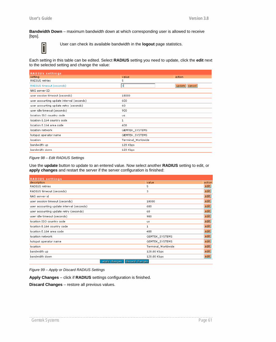
User’s Guide Version 3.8
Gemtek Systems Page 61
Bandwidth Down – maximum bandwidth down at which corresponding user is allowed to receive [bps].
User can check its available bandwidth in the logout page statistics.
Each setting in this table can be edited. Select RADIUS setting you need to update, click the edit next to the selected setting and change the value:
Figure 98 – Edit RADIUS Settings
Use the update button to update to an entered value. Now select another RADIUS setting to edit, or apply changes and restart the server if the server configuration is finished:
Figure 99 – Apply or Discard RADIUS Settings
Apply Changes – click if RADIUS settings configuration is finished.
Discard Changes – restore all previous values.

User’s Guide Version 3.8
Gemtek Systems Page 62
Network Interface | RADIUS | RADIUS Servers
Up to 32 different RADIUS servers can be configured under the RADIUS servers menu.
By default, one RADIUS server is specified for the system:
Figure 100 – RADIUS Servers Settings
New – add new RADIUS server.
Details – click on details to get more information about RADIUS server settings.
Edit – edit selected RADIUS server settings.
Delete – remove selected RADIUS server.
To view complete RADIUS server settings, click the details button in the action column:
Figure 101 – RADIUS Server's Details
To edit RADIUS server click the edit button:

User’s Guide Version 3.8
Gemtek Systems Page 63
Figure 102 – Add New RADIUS Server
Name – specify the new RADIUS server name.
Default – check the check box to make the selected RADIUS the default server.
Authentication IP – authentication RADIUS server IP address [dots and digits].
Authentication Port – specify the network port used to communicate with RADIUS [1-65535].
The port default value of 1812 is based on RFC 2138 "Remote Authentication Dial-in User Service (RADIUS)".
Authentication Secret – shared secret string that is used to encrypt data frames used for authentication server.
Accounting IP – accounting RADIUS server IP address [dots and digits].
Accounting Port – specify the network port used to communicate with RADIUS [1-65535].
Accounting Secret – shared secret string that is used to encrypt data frames used for accounting server.
Backup IP – backup RADIUS server IP address [dots and digits].
Backup Port – specify the network port used to communicate with RADIUS [1-65535].
Backup Secret – shared secret string that is used to encrypt data frames used for backup server.
Shared secret must be the same on RADIUS server and RADIUS client.
Reverse Accounting – [enabled/disabled]. The RADIUS accounting request contains Acc-Input-Octets and Acc-Output-Octets attributes. The interpretation of these attributes according the RFC2866 is relative to the point of view. If this point is at the AC - Acct-Input* attributes should contain the bytes/packets received at AC port from the client and Acct-Output* attributes should contain bytes/packets sent from AC port to the client. If we move this point to the client - we will get the reversing of Acct-Input* and Acct-Output* attributes values. The Acct-Input* then should contain bytes/packets received from AC, what is bytes/packets that AC sent to the user in AC point of view and what was Acct-Output*.
The AC implementation of RADIUS accounting request is at the client point of view (reverse accounting is disabled).
The value "disabled" means that Acct-Input* RADIUS attributes will contain bytes/packets sent to the client and Acct-Output* RADIUS attributes will contain bytes/packets received from the client during the curse of service being provided.
The value "enabled" means that info in the Acct-Input* and Acct-Output* RADIUS attributes will be swapped (reversed). That is the Acct-Input* will contain bytes/packets received from the client and the Acct-Output* will contain bytes/packets sent to the client.
Strip WISP – [enabled/disabled] select ‘enabled' if you want to strip WISP domain name before sending it to the RADIUS server. Stripping means removing everything before the “/” character including character itself for such user name login format like: “WISPdomain/username”.
Select “disabled” if you need to send the user login name to RADIUS server unmodified. Some RADIUS servers can be configured in such way that requires full-unmodified user name to be sent.
UAM authentication method – select authentication method from drop-down menu:
PAP – Password Authentication Protocol CHAP – Challenge Handshake Authentication Protocol MSCHAP1 – Microsoft Challenge Handshake Authentication Protocol version 1 MSCHAP2 – Microsoft Challenge Handshake Authentication Protocol version 2

User’s Guide Version 3.8
Gemtek Systems Page 64
Update – add new specified RADIUS server.
Cancel – restore all previous values.
After adding a new RADIUS server or editing an existing one, the following controls appears:
Apply Changes – save changed configuration.
Discard Changes – discard all changes.
Restart – after applying changes to the system, you should restart the controller to make applied changes work.
Network Interface | RADIUS | WISP
Up to 32 WISP entries can be defined using the network interface | RADIUS | WISP menu.
Different WISPs (Wireless Internet Service Providers) can be associated with appropriate RADIUS servers and device interfaces using the network interface | RADIUS | WISP menu:
Figure 103 – WISP Menu
Domain policy means G-4200 use which policy to fetch WISP name from user name then to judge user belong which domain.
Hotspot owner can use three policy to judge the WISP name from user name:
1. username follow the format: username@WISPdomain
2. username follow the format: WISPdomain/username
3. use prefix of username as wisp name, the range of prefix length is from 2 to 6.
Figure 104 – Domain Policy
New – click to define WISP for RADIUS server.
Figure 105 – Define New WISP
Name – new WISP domain name [string, up to 256 symbols, no space, dot or dash allowed].
RADIUS Name – select RADIUS for new WISP from list box [non editable].
Bound To – select the WISP binder interface [none/ixp0//vlan[n]]. The WISP can be associated with appropriate device interface.
Update – system with new WISP.
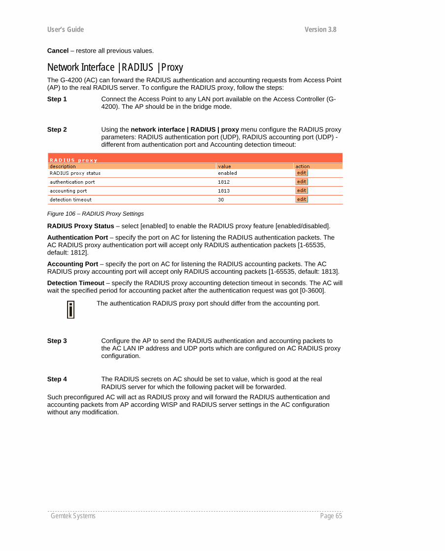
User’s Guide Version 3.8
Gemtek Systems Page 65
Cancel – restore all previous values.
Network Interface | RADIUS | Proxy The G-4200 (AC) can forward the RADIUS authentication and accounting requests from Access Point (AP) to the real RADIUS server. To configure the RADIUS proxy, follow the steps:
Step 1 Connect the Access Point to any LAN port available on the Access Controller (G-4200). The AP should be in the bridge mode.
Step 2 Using the network interface | RADIUS | proxy menu configure the RADIUS proxy parameters: RADIUS authentication port (UDP), RADIUS accounting port (UDP) - different from authentication port and Accounting detection timeout:
Figure 106 – RADIUS Proxy Settings
RADIUS Proxy Status – select [enabled] to enable the RADIUS proxy feature [enabled/disabled].
Authentication Port – specify the port on AC for listening the RADIUS authentication packets. The AC RADIUS proxy authentication port will accept only RADIUS authentication packets [1-65535, default: 1812].
Accounting Port – specify the port on AC for listening the RADIUS accounting packets. The AC RADIUS proxy accounting port will accept only RADIUS accounting packets [1-65535, default: 1813].
Detection Timeout – specify the RADIUS proxy accounting detection timeout in seconds. The AC will wait the specified period for accounting packet after the authentication request was got [0-3600].
The authentication RADIUS proxy port should differ from the accounting port.
Step 3 Configure the AP to send the RADIUS authentication and accounting packets to the AC LAN IP address and UDP ports which are configured on AC RADIUS proxy configuration.
Step 4 The RADIUS secrets on AC should be set to value, which is good at the real RADIUS server for which the following packet will be forwarded.
Such preconfigured AC will act as RADIUS proxy and will forward the RADIUS authentication and accounting packets from AP according WISP and RADIUS server settings in the AC configuration without any modification.

User’s Guide Version 3.8
Gemtek Systems Page 66
Network Interface | RADIUS | Accounting Backup The administrator can backup the hotspot subscribers’ RADIUS accounting information in two ways:
Via syslog protocol to the specified host Download to the selected location (e.g. on your PC)
Use the network interface | RADIUS | accounting backup menu:
Figure 107 – Accounting Backup
Backup via syslog – enable this type to send the RADIUS accounting information via syslog protocol to the specified host [enable/disable] and note that the Host IP specification is obligatory.
Host – enter host IP address where to send accounting backup messages.
Backup to local file – enable this option, and the download button appears:
Figure 108 – Accounting Backup enable
Download – click the button to download the accounting information file to your selected location.
Both types of accounting backup can be enabled.
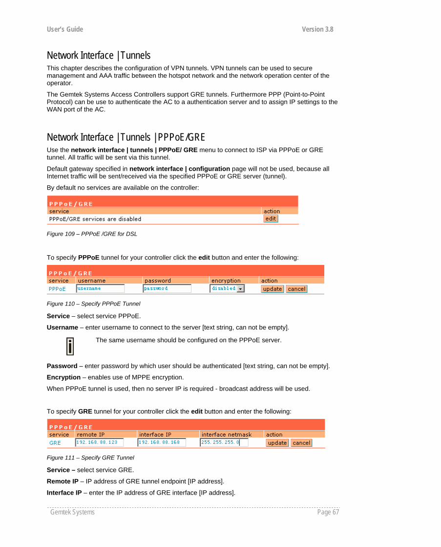
User’s Guide Version 3.8
Gemtek Systems Page 67
Network Interface | Tunnels This chapter describes the configuration of VPN tunnels. VPN tunnels can be used to secure management and AAA traffic between the hotspot network and the network operation center of the operator.
The Gemtek Systems Access Controllers support GRE tunnels. Furthermore PPP (Point-to-Point Protocol) can be use to authenticate the AC to a authentication server and to assign IP settings to the WAN port of the AC.
Network Interface | Tunnels | PPPoE/GRE Use the network interface | tunnels | PPPoE/ GRE menu to connect to ISP via PPPoE or GRE tunnel. All traffic will be sent via this tunnel.
Default gateway specified in network interface | configuration page will not be used, because all Internet traffic will be sent/received via the specified PPPoE or GRE server (tunnel).
By default no services are available on the controller:
Figure 109 – PPPoE /GRE for DSL
To specify PPPoE tunnel for your controller click the edit button and enter the following:
Figure 110 – Specify PPPoE Tunnel
Service – select service PPPoE.
Username – enter username to connect to the server [text string, can not be empty].
The same username should be configured on the PPPoE server.
Password – enter password by which user should be authenticated [text string, can not be empty].
Encryption – enables use of MPPE encryption.
When PPPoE tunnel is used, then no server IP is required - broadcast address will be used.
To specify GRE tunnel for your controller click the edit button and enter the following:
Figure 111 – Specify GRE Tunnel
Service – select service GRE.
Remote IP – IP address of GRE tunnel endpoint [IP address].
Interface IP – enter the IP address of GRE interface [IP address].

User’s Guide Version 3.8
Gemtek Systems Page 68
Interface Netmask – enter the netmask of GRE interface [netmask].
Network Interface | Tunnels | GRE Client for VPN
Up to 16 GRE tunnels can be created in the system.
GRE (Generic Routing Encapsulation) tunnel is one of the solutions for tunneling private network over the TCP/IP connection (e.g. PPTP, L2TP, PPPoE). GRE tunnel does not use encryption. It only encapsulates data and sends it over the Internet. So the administrator should take care that no unencrypted private information is going through the GRE tunnel. By default there is no GRE tunnels on the AC:
Figure 112 – GRE Tunnel
To specify new GRE tunnel for your AC, click the new button:
See the following example to understand GRE settings.
Example:
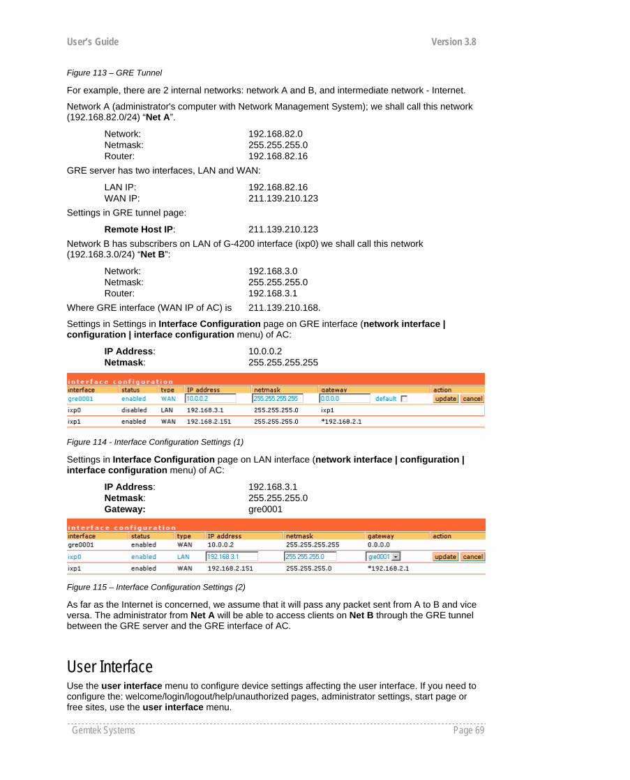
User’s Guide Version 3.8
Gemtek Systems Page 69
Figure 113 – GRE Tunnel
For example, there are 2 internal networks: network A and B, and intermediate network - Internet.
Network A (administrator's computer with Network Management System); we shall call this network (192.168.82.0/24) “Net A”.
Network: 192.168.82.0 Netmask: 255.255.255.0 Router: 192.168.82.16
GRE server has two interfaces, LAN and WAN:
LAN IP: 192.168.82.16 WAN IP: 211.139.210.123
Settings in GRE tunnel page:
Remote Host IP: 211.139.210.123 Network B has subscribers on LAN of G-4200 interface (ixp0) we shall call this network (192.168.3.0/24) “Net B”:
Network: 192.168.3.0 Netmask: 255.255.255.0 Router: 192.168.3.1
Where GRE interface (WAN IP of AC) is 211.139.210.168.
Settings in Settings in Interface Configuration page on GRE interface (network interface | configuration | interface configuration menu) of AC:
IP Address: 10.0.0.2 Netmask: 255.255.255.255
Figure 114 - Interface Configuration Settings (1)
Settings in Interface Configuration page on LAN interface (network interface | configuration | interface configuration menu) of AC:
IP Address: 192.168.3.1 Netmask: 255.255.255.0 Gateway: gre0001
Figure 115 – Interface Configuration Settings (2)
As far as the Internet is concerned, we assume that it will pass any packet sent from A to B and vice versa. The administrator from Net A will be able to access clients on Net B through the GRE tunnel between the GRE server and the GRE interface of AC.
User Interface Use the user interface menu to configure device settings affecting the user interface. If you need to configure the: welcome/login/logout/help/unauthorized pages, administrator settings, start page or free sites, use the user interface menu.
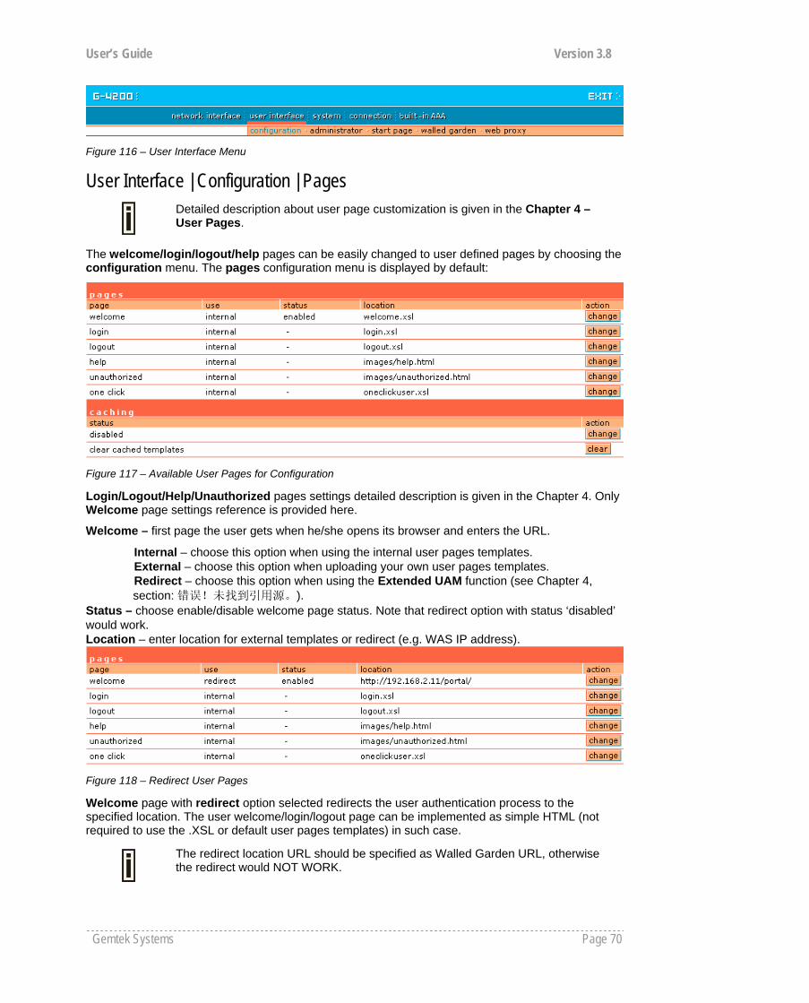
User’s Guide Version 3.8
Gemtek Systems Page 70
Figure 116 – User Interface Menu
User Interface | Configuration | Pages
Detailed description about user page customization is given in the Chapter 4 – User Pages.
The welcome/login/logout/help pages can be easily changed to user defined pages by choosing the configuration menu. The pages configuration menu is displayed by default:
Figure 117 – Available User Pages for Configuration
Login/Logout/Help/Unauthorized pages settings detailed description is given in the Chapter 4. Only Welcome page settings reference is provided here.
Welcome – first page the user gets when he/she opens its browser and enters the URL.
Internal – choose this option when using the internal user pages templates. External – choose this option when uploading your own user pages templates. Redirect – choose this option when using the Extended UAM function (see Chapter 4, section: 错误!未找到引用源。).
Status – choose enable/disable welcome page status. Note that redirect option with status ‘disabled’ would work. Location – enter location for external templates or redirect (e.g. WAS IP address).
Figure 118 – Redirect User Pages
Welcome page with redirect option selected redirects the user authentication process to the specified location. The user welcome/login/logout page can be implemented as simple HTML (not required to use the .XSL or default user pages templates) in such case.
The redirect location URL should be specified as Walled Garden URL, otherwise the redirect would NOT WORK.

User’s Guide Version 3.8
Gemtek Systems Page 71
Figure 119 – Caching Option
Caching option can be used for caching the external uploaded user pages (available choice: enabled/disabled)
Clear – click the button to clear cached user pages.
Controller cache is also cleared after device reboot/reset.
User Interface | Configuration | Upload
Look for the user pages template samples in the Installation CD delivered to you with the product.
Figure 120 – Upload Page
Delete – click the button to delete earlier uploaded files from Hotspot-in-a-Box memory.
Upload – click the button to select and upload new user pages.
How to upload user pages see in the Chapter 4 – User Pages.
User Interface | Configuration | Headers System administrator can set HTML headers encoding and language settings for AC web management interface and new uploaded user pages. Select user interface | configuration | headers menu:
Figure 121 – HTTP Headers Settings
G-4200 device supports some http META tags. Syntax of such META tags: <META HTTP-EQUIV="name" CONTENT="content">
Currently G-4200 supports Content-Type and Content-Language tags:
Content-Type is used to define document char set (used, when text has non-Latin letters, like language letters).
Content-Language may be used to declare the natural language of the document.
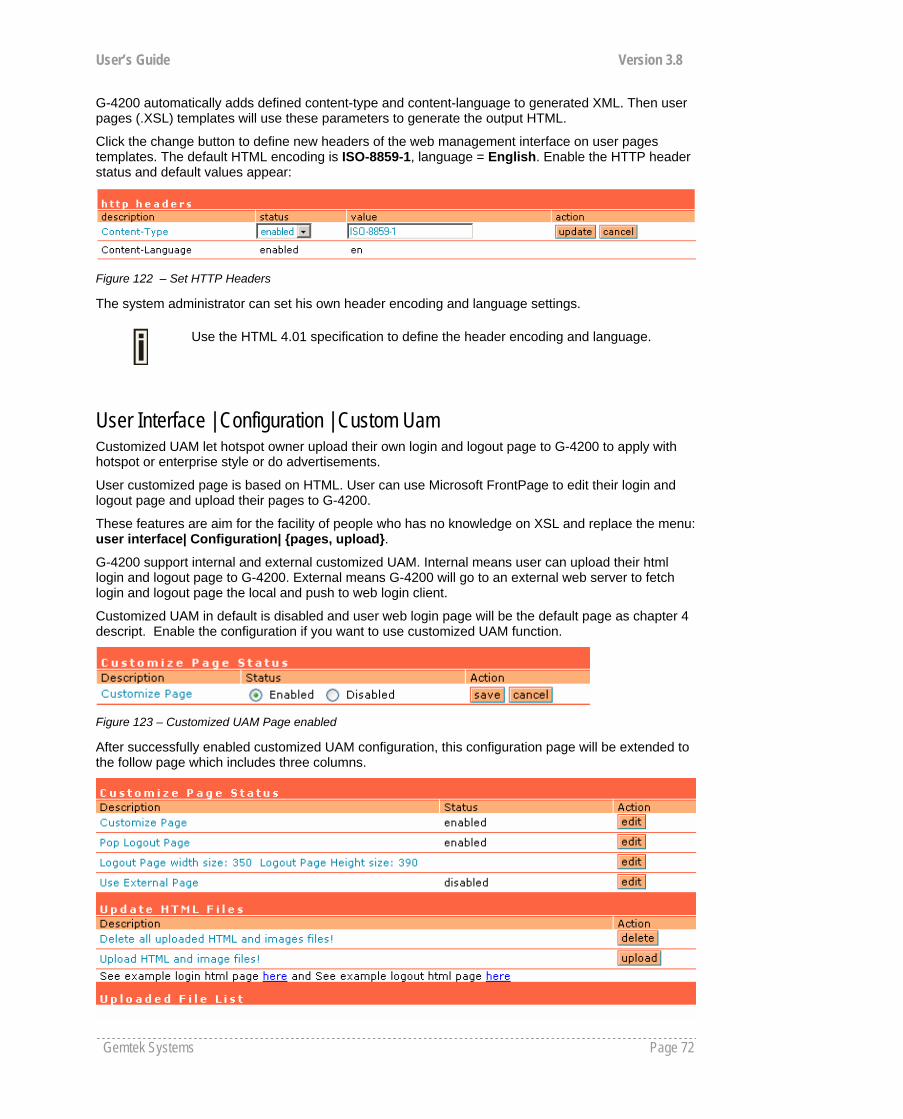
User’s Guide Version 3.8
Gemtek Systems Page 72
G-4200 automatically adds defined content-type and content-language to generated XML. Then user pages (.XSL) templates will use these parameters to generate the output HTML.
Click the change button to define new headers of the web management interface on user pages templates. The default HTML encoding is ISO-8859-1, language = English. Enable the HTTP header status and default values appear:
Figure 122 – Set HTTP Headers
The system administrator can set his own header encoding and language settings.
User Interface | Configuration | Custom Uam Customized UAM let hotspot owner upload their own login and logout page to G-4200 to apply with hotspot or enterprise style or do advertisements.
User customized page is based on HTML. User can use Microsoft FrontPage to edit their login and logout page and upload their pages to G-4200.
These features are aim for the facility of people who has no knowledge on XSL and replace the menu: user interface| Configuration| {pages, upload}.
G-4200 support internal and external customized UAM. Internal means user can upload their html login and logout page to G-4200. External means G-4200 will go to an external web server to fetch login and logout page the local and push to web login client.
Customized UAM in default is disabled and user web login page will be the default page as chapter 4 descript. Enable the configuration if you want to use customized UAM function.
Figure 123 – Customized UAM Page enabled
After successfully enabled customized UAM configuration, this configuration page will be extended to the follow page which includes three columns.
Use the HTML 4.01 specification to define the header encoding and language.
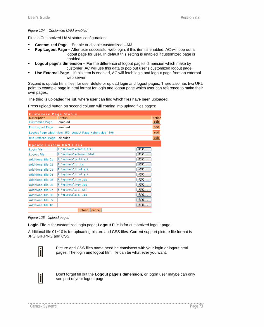
User’s Guide Version 3.8
Gemtek Systems Page 73
Figure 124 – Customize UAM enabled
First is Customized UAM status configuration:
Customized Page – Enable or disable customized UAM Pop Logout Page – After user successful web login, if this item is enabled, AC will pop out a
logout page for user. In default this setting is enabled if customized page is enabled.
Logout page’s dimension – For the difference of logout page’s dimension which make by customer, AC will use this data to pop out user’s customized logout page.
Use External Page – If this item is enabled, AC will fetch login and logout page from an external web server.
Second is update html files, for user delete or upload login and logout pages. There also has two URL point to example page in html format for login and logout page which user can reference to make their own pages.
The third is uploaded file list, where user can find which files have been uploaded.
Press upload button on second column will coming into upload files pages:
Figure 125 –Upload pages
Login File is for customized login page; Logout File is for customized logout page.
Additional file 01~10 is for uploading picture and CSS files. Current support picture file format is JPG,GIF,PNG and CSS.
Picture and CSS files name need be consistent with your login or logout html pages. The login and logout html file can be what ever you want.
Don’t forget fill out the Logout page’s dimension, or logon user maybe can only see part of your logout page.
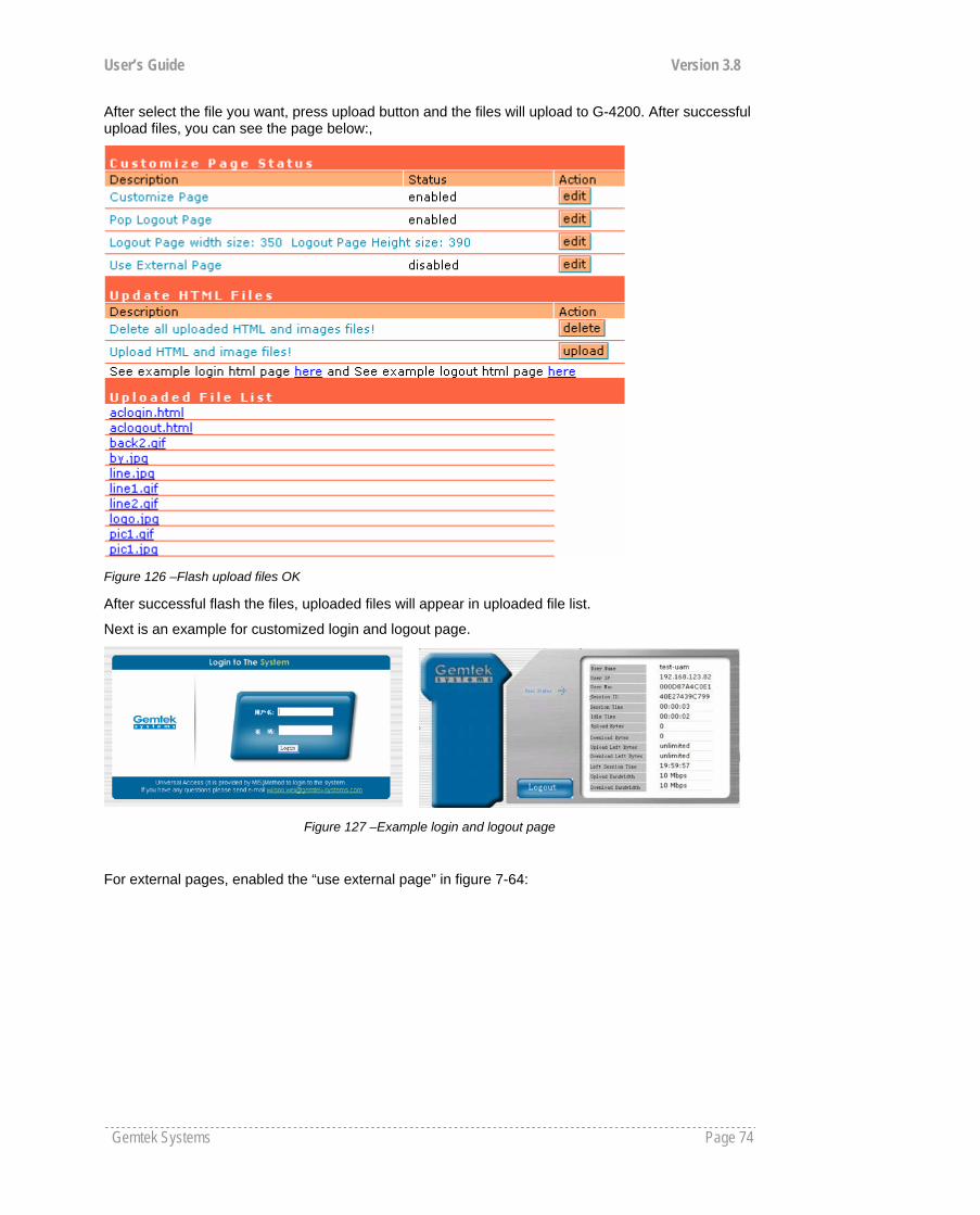
User’s Guide Version 3.8
Gemtek Systems Page 74
After select the file you want, press upload button and the files will upload to G-4200. After successful upload files, you can see the page below:,
Figure 126 –Flash upload files OK
After successful flash the files, uploaded files will appear in uploaded file list.
Next is an example for customized login and logout page.
Figure 127 –Example login and logout page
For external pages, enabled the “use external page” in figure 7-64:
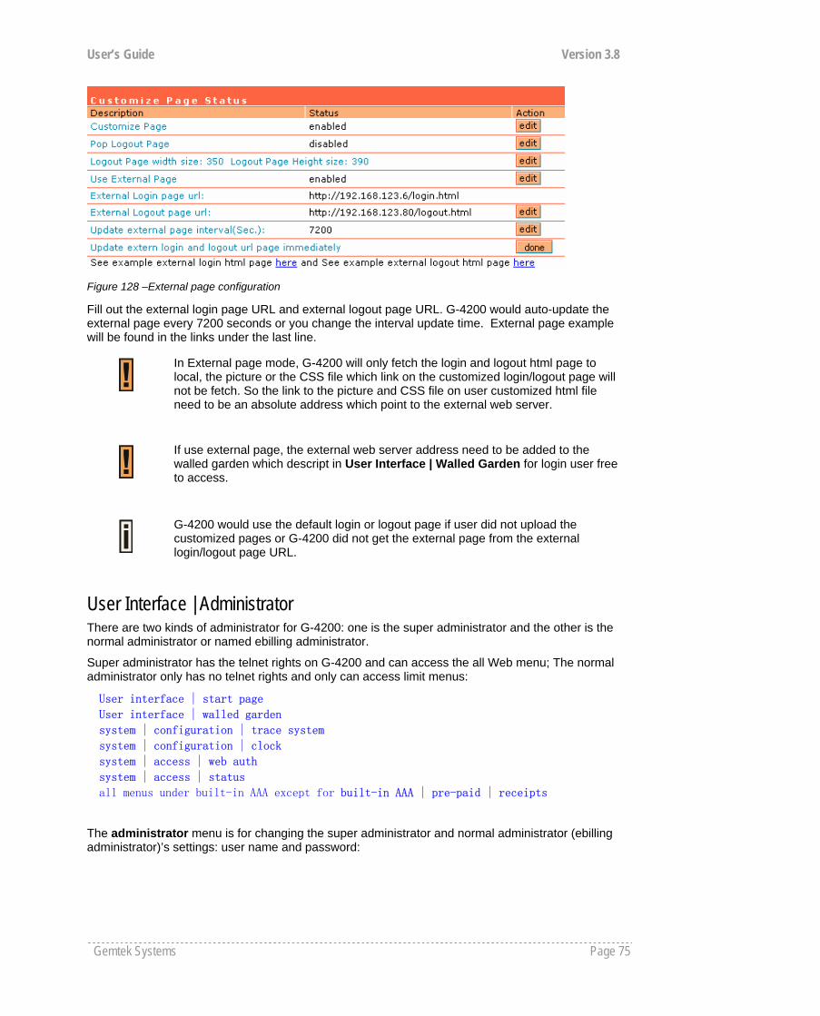
User’s Guide Version 3.8
Gemtek Systems Page 75
Figure 128 –External page configuration
Fill out the external login page URL and external logout page URL. G-4200 would auto-update the external page every 7200 seconds or you change the interval update time. External page example will be found in the links under the last line.
User Interface | Administrator There are two kinds of administrator for G-4200: one is the super administrator and the other is the normal administrator or named ebilling administrator.
Super administrator has the telnet rights on G-4200 and can access the all Web menu; The normal administrator only has no telnet rights and only can access limit menus:
User interface | start page User interface | walled garden system | configuration | trace system system | configuration | clock system | access | web auth system | access | status all menus under built-in AAA except for built-in AAA | pre-paid | receipts
The administrator menu is for changing the super administrator and normal administrator (ebilling administrator)’s settings: user name and password:
In External page mode, G-4200 will only fetch the login and logout html page to local, the picture or the CSS file which link on the customized login/logout page will not be fetch. So the link to the picture and CSS file on user customized html file need to be an absolute address which point to the external web server.
If use external page, the external web server address need to be added to the walled garden which descript in User Interface | Walled Garden for login user free to access.
G-4200 would use the default login or logout page if user did not upload the customized pages or G-4200 did not get the external page from the external login/logout page URL.
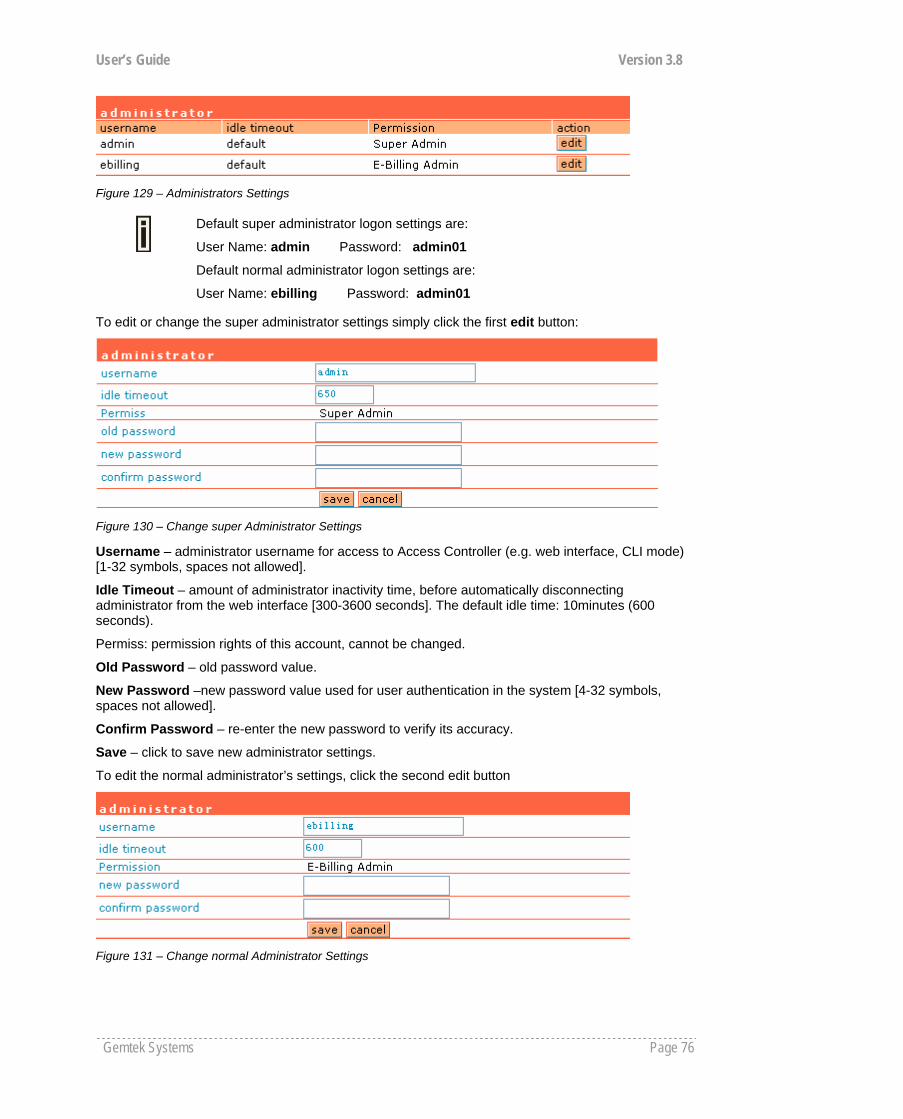
User’s Guide Version 3.8
Gemtek Systems Page 76
Figure 129 – Administrators Settings
Default super administrator logon settings are:
User Name: admin Password: admin01
Default normal administrator logon settings are:
User Name: ebilling Password: admin01
To edit or change the super administrator settings simply click the first edit button:
Figure 130 – Change super Administrator Settings
Username – administrator username for access to Access Controller (e.g. web interface, CLI mode) [1-32 symbols, spaces not allowed].
Idle Timeout – amount of administrator inactivity time, before automatically disconnecting administrator from the web interface [300-3600 seconds]. The default idle time: 10minutes (600 seconds).
Permiss: permission rights of this account, cannot be changed.
Old Password – old password value.
New Password –new password value used for user authentication in the system [4-32 symbols, spaces not allowed].
Confirm Password – re-enter the new password to verify its accuracy.
Save – click to save new administrator settings.
To edit the normal administrator’s settings, click the second edit button
Figure 131 – Change normal Administrator Settings
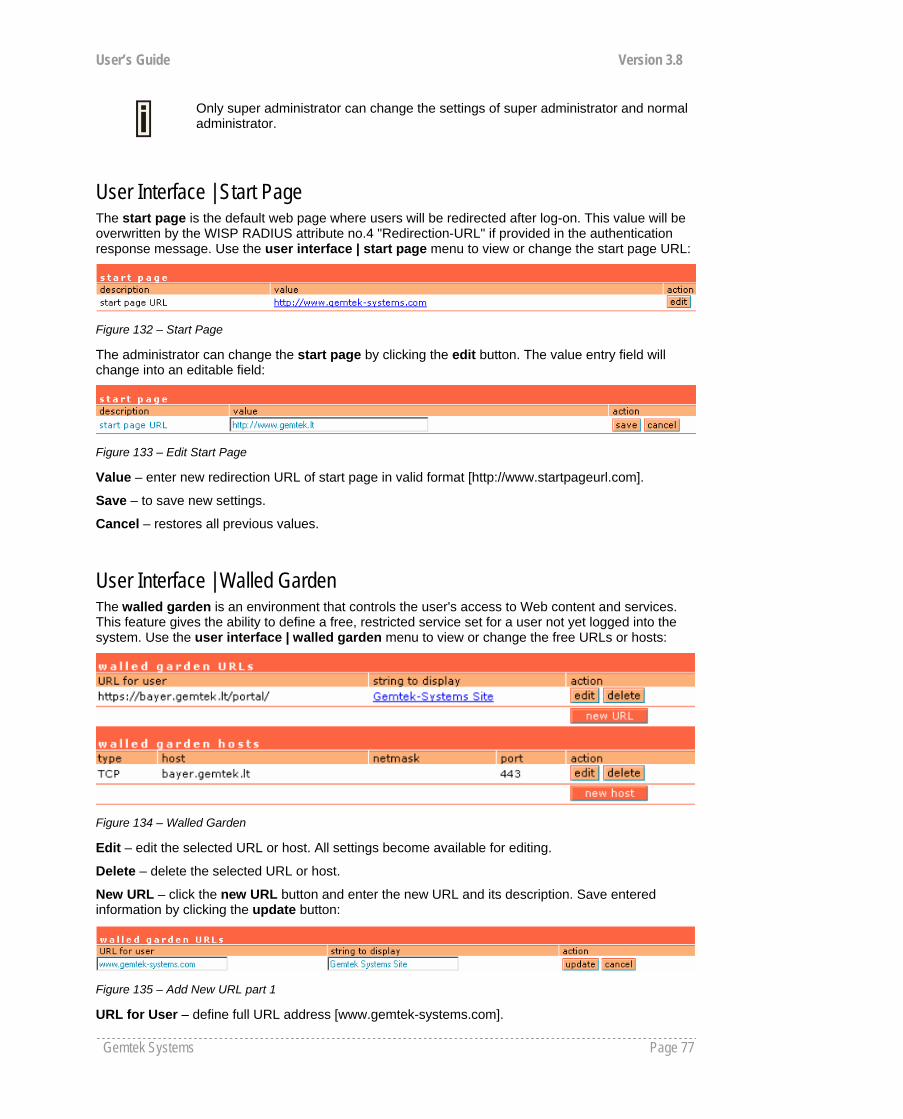
User’s Guide Version 3.8
Gemtek Systems Page 77
Only super administrator can change the settings of super administrator and normal administrator.
User Interface | Start Page The start page is the default web page where users will be redirected after log-on. This value will be overwritten by the WISP RADIUS attribute no.4 "Redirection-URL" if provided in the authentication response message. Use the user interface | start page menu to view or change the start page URL:
Figure 132 – Start Page
The administrator can change the start page by clicking the edit button. The value entry field will change into an editable field:
Figure 133 – Edit Start Page
Value – enter new redirection URL of start page in valid format [http://www.startpageurl.com].
Save – to save new settings.
Cancel – restores all previous values.
User Interface | Walled Garden The walled garden is an environment that controls the user's access to Web content and services. This feature gives the ability to define a free, restricted service set for a user not yet logged into the system. Use the user interface | walled garden menu to view or change the free URLs or hosts:
Figure 134 – Walled Garden
Edit – edit the selected URL or host. All settings become available for editing.
Delete – delete the selected URL or host.
New URL – click the new URL button and enter the new URL and its description. Save entered information by clicking the update button:
Figure 135 – Add New URL part 1
URL for User – define full URL address [www.gemtek-systems.com].

User’s Guide Version 3.8
Gemtek Systems Page 78
String to Display – site description visible to user as link on the welcome and login page:
Figure 136 – Walled Garden link in the Welcome Page
New Host – If you need to define hosts (web servers) for walled garden, specify hosts by clicking the new host button and click the update button:
Figure 137 – Walled Garden Host
Type –select the data traffic protocol for host server [TCP/UDP].
Host – Web server address [IP address or host name].
Netmask – enter the network mask to specify the host servers network.
Port – network port, which is used to reach the host [1-65535]. For standard protocols use the default ports:
Protocol Port HTTP 80 HTTPS 443 FTP 21
User Interface | Web Proxy The enabled web proxy allows any clients’ connections with configured proxy settings on their browsers. The AC accepts any client proxy configurations and grants the access to the Internet. The system administrator should list only ports the AC is listening on for proxy requests.
Figure 138 – Web Proxy
Web proxy is enabled by default and the port numbers are: 3128 and 8080.
To add more port number for web proxy, click the new button:
Figure 139 – Add Web Proxy Port
Port – add port number for web proxy to listen to [1-65535].
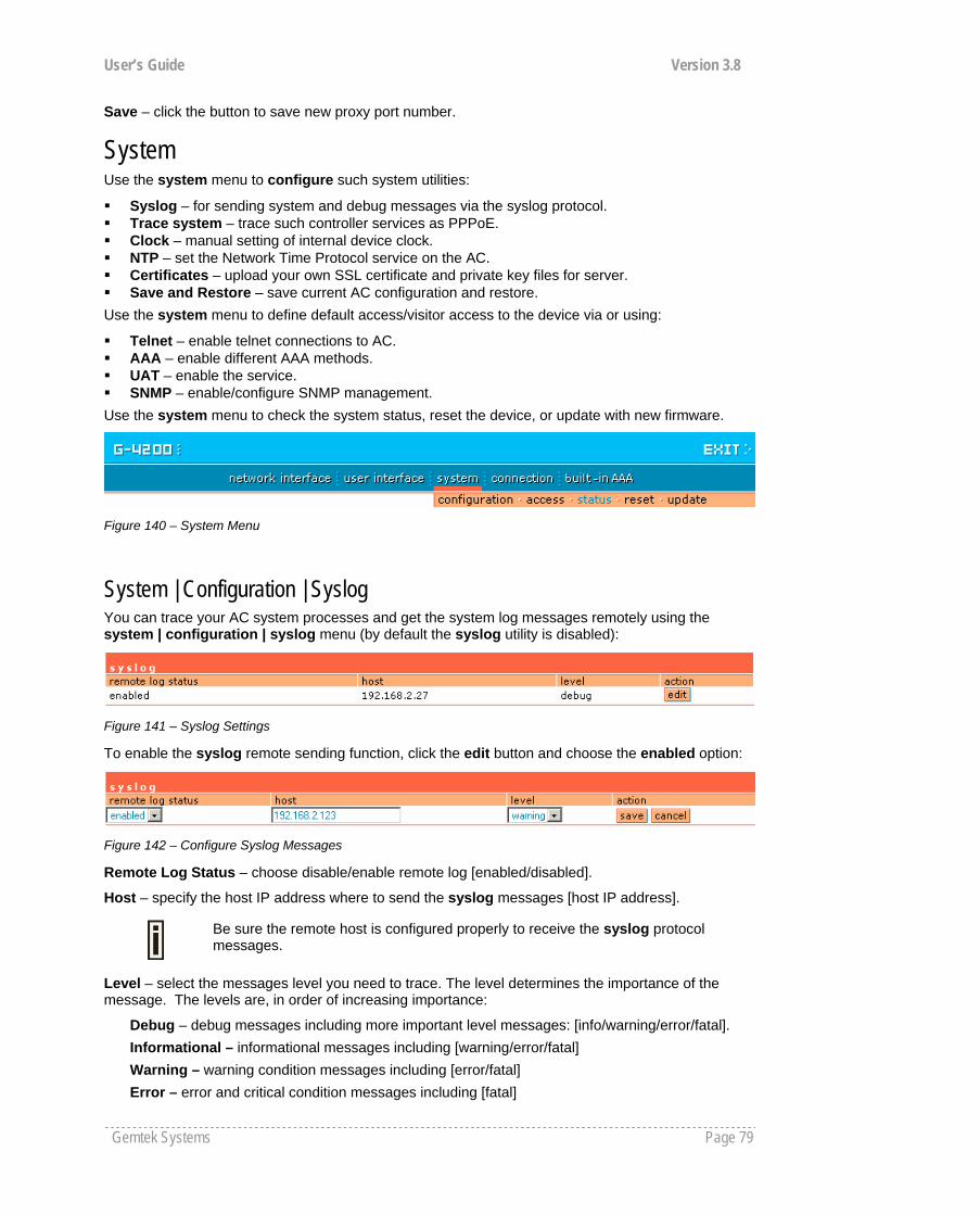
User’s Guide Version 3.8
Gemtek Systems Page 79
Save – click the button to save new proxy port number.
System
Use the system menu to configure such system utilities:
Syslog – for sending system and debug messages via the syslog protocol. Trace system – trace such controller services as PPPoE. Clock – manual setting of internal device clock. NTP – set the Network Time Protocol service on the AC. Certificates – upload your own SSL certificate and private key files for server. Save and Restore – save current AC configuration and restore.
Use the system menu to define default access/visitor access to the device via or using:
Telnet – enable telnet connections to AC. AAA – enable different AAA methods. UAT – enable the service. SNMP – enable/configure SNMP management.
Use the system menu to check the system status, reset the device, or update with new firmware.
Figure 140 – System Menu
System | Configuration | Syslog You can trace your AC system processes and get the system log messages remotely using the system | configuration | syslog menu (by default the syslog utility is disabled):
Figure 141 – Syslog Settings
To enable the syslog remote sending function, click the edit button and choose the enabled option:
Figure 142 – Configure Syslog Messages
Remote Log Status – choose disable/enable remote log [enabled/disabled].
Host – specify the host IP address where to send the syslog messages [host IP address].
Be sure the remote host is configured properly to receive the syslog protocol messages.
Level – select the messages level you need to trace. The level determines the importance of the message. The levels are, in order of increasing importance:
Debug – debug messages including more important level messages: [info/warning/error/fatal]. Informational – informational messages including [warning/error/fatal] Warning – warning condition messages including [error/fatal] Error – error and critical condition messages including [fatal]
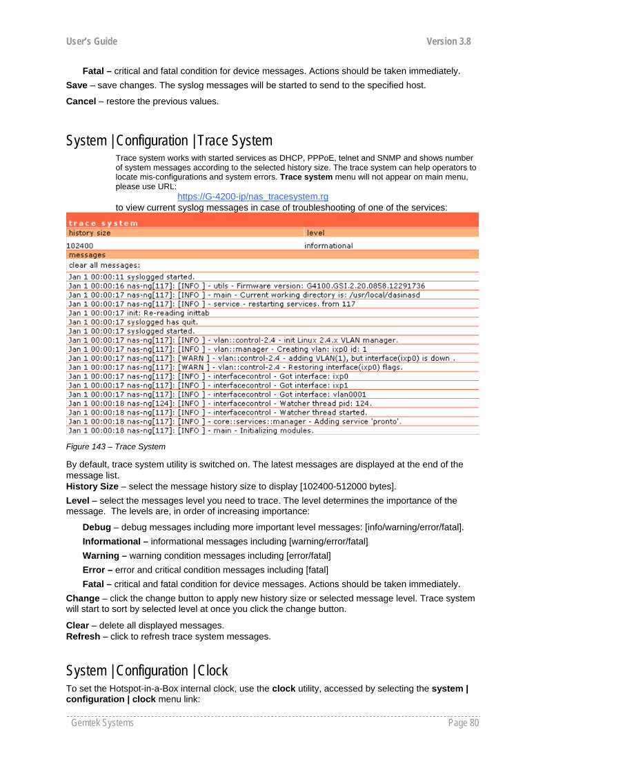
User’s Guide Version 3.8
Gemtek Systems Page 80
Fatal – critical and fatal condition for device messages. Actions should be taken immediately. Save – save changes. The syslog messages will be started to send to the specified host.
Cancel – restore the previous values.
System | Configuration | Trace System Trace system works with started services as DHCP, PPPoE, telnet and SNMP and shows number of system messages according to the selected history size. The trace system can help operators to locate mis-configurations and system errors. Trace system menu will not appear on main menu, please use URL: https://G-4200-ip/nas_tracesystem.rg to view current syslog messages in case of troubleshooting of one of the services:
Figure 143 – Trace System
By default, trace system utility is switched on. The latest messages are displayed at the end of the message list. History Size – select the message history size to display [102400-512000 bytes]. Level – select the messages level you need to trace. The level determines the importance of the message. The levels are, in order of increasing importance:
Debug – debug messages including more important level messages: [info/warning/error/fatal]. Informational – informational messages including [warning/error/fatal] Warning – warning condition messages including [error/fatal] Error – error and critical condition messages including [fatal] Fatal – critical and fatal condition for device messages. Actions should be taken immediately.
Change – click the change button to apply new history size or selected message level. Trace system will start to sort by selected level at once you click the change button.
Clear – delete all displayed messages. Refresh – click to refresh trace system messages.
System | Configuration | Clock To set the Hotspot-in-a-Box internal clock, use the clock utility, accessed by selecting the system | configuration | clock menu link:
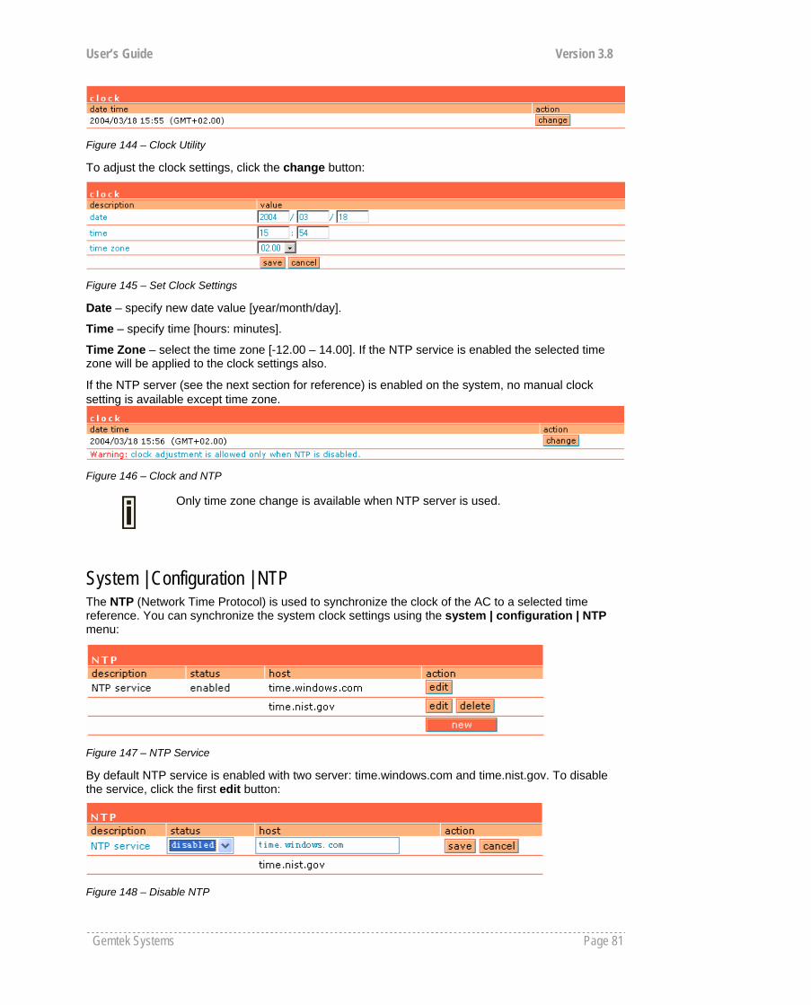
User’s Guide Version 3.8
Gemtek Systems Page 81
Figure 144 – Clock Utility
To adjust the clock settings, click the change button:
Figure 145 – Set Clock Settings
Date – specify new date value [year/month/day].
Time – specify time [hours: minutes].
Time Zone – select the time zone [-12.00 – 14.00]. If the NTP service is enabled the selected time zone will be applied to the clock settings also.
If the NTP server (see the next section for reference) is enabled on the system, no manual clock setting is available except time zone.
Figure 146 – Clock and NTP
Only time zone change is available when NTP server is used.
System | Configuration | NTP The NTP (Network Time Protocol) is used to synchronize the clock of the AC to a selected time reference. You can synchronize the system clock settings using the system | configuration | NTP menu:
Figure 147 – NTP Service
By default NTP service is enabled with two server: time.windows.com and time.nist.gov. To disable the service, click the first edit button:
Figure 148 – Disable NTP
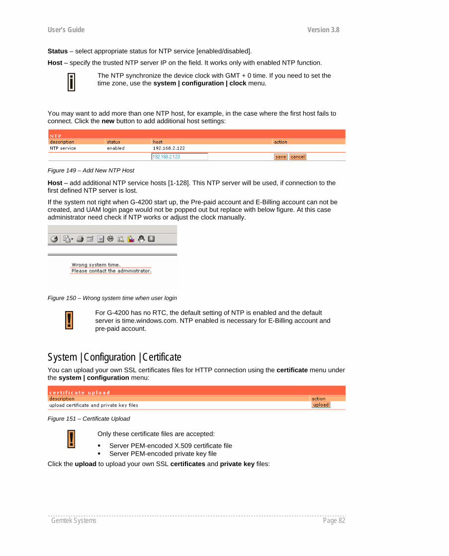
User’s Guide Version 3.8
Gemtek Systems Page 82
Status – select appropriate status for NTP service [enabled/disabled].
Host – specify the trusted NTP server IP on the field. It works only with enabled NTP function.
The NTP synchronize the device clock with GMT + 0 time. If you need to set the time zone, use the system | configuration | clock menu.
You may want to add more than one NTP host, for example, in the case where the first host fails to connect. Click the new button to add additional host settings:
Figure 149 – Add New NTP Host
Host – add additional NTP service hosts [1-128]. This NTP server will be used, if connection to the first defined NTP server is lost.
If the system not right when G-4200 start up, the Pre-paid account and E-Billing account can not be created, and UAM login page would not be popped out but replace with below figure. At this case administrator need check if NTP works or adjust the clock manually.
Figure 150 – Wrong system time when user login
System | Configuration | Certificate You can upload your own SSL certificates files for HTTP connection using the certificate menu under the system | configuration menu:
Figure 151 – Certificate Upload
Only these certificate files are accepted:
Server PEM-encoded X.509 certificate file Server PEM-encoded private key file
Click the upload to upload your own SSL certificates and private key files:
For G-4200 has no RTC, the default setting of NTP is enabled and the default server is time.windows.com. NTP enabled is necessary for E-Billing account and pre-paid account.
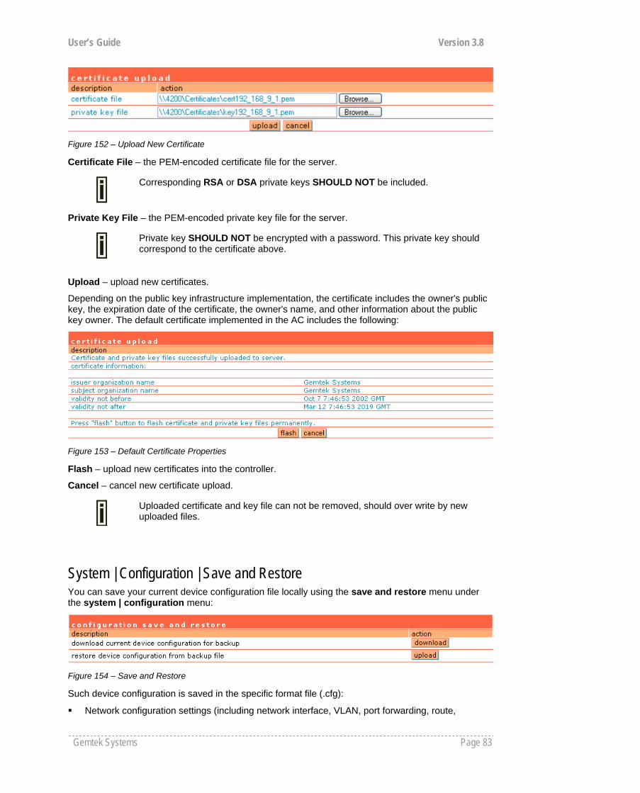
User’s Guide Version 3.8
Gemtek Systems Page 83
Figure 152 – Upload New Certificate
Certificate File – the PEM-encoded certificate file for the server.
Corresponding RSA or DSA private keys SHOULD NOT be included.
Private Key File – the PEM-encoded private key file for the server.
Private key SHOULD NOT be encrypted with a password. This private key should correspond to the certificate above.
Upload – upload new certificates.
Depending on the public key infrastructure implementation, the certificate includes the owner's public key, the expiration date of the certificate, the owner's name, and other information about the public key owner. The default certificate implemented in the AC includes the following:
Figure 153 – Default Certificate Properties
Flash – upload new certificates into the controller.
Cancel – cancel new certificate upload.
Uploaded certificate and key file can not be removed, should over write by new uploaded files.
System | Configuration | Save and Restore You can save your current device configuration file locally using the save and restore menu under the system | configuration menu:
Figure 154 – Save and Restore
Such device configuration is saved in the specific format file (.cfg):
Network configuration settings (including network interface, VLAN, port forwarding, route,
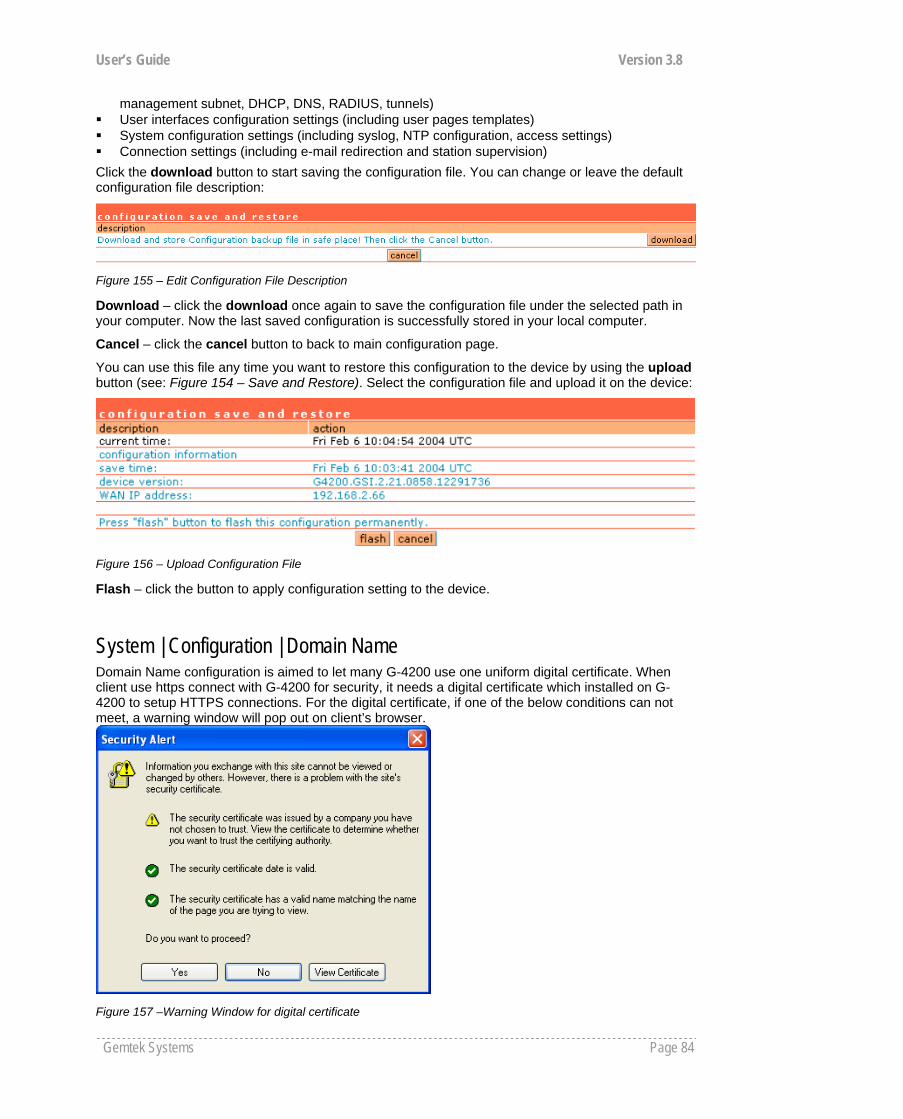
User’s Guide Version 3.8
Gemtek Systems Page 84
management subnet, DHCP, DNS, RADIUS, tunnels) User interfaces configuration settings (including user pages templates) System configuration settings (including syslog, NTP configuration, access settings) Connection settings (including e-mail redirection and station supervision)
Click the download button to start saving the configuration file. You can change or leave the default configuration file description:
Figure 155 – Edit Configuration File Description
Download – click the download once again to save the configuration file under the selected path in your computer. Now the last saved configuration is successfully stored in your local computer.
Cancel – click the cancel button to back to main configuration page.
You can use this file any time you want to restore this configuration to the device by using the upload button (see: Figure 154 – Save and Restore). Select the configuration file and upload it on the device:
Figure 156 – Upload Configuration File
Flash – click the button to apply configuration setting to the device.
System | Configuration | Domain Name Domain Name configuration is aimed to let many G-4200 use one uniform digital certificate. When client use https connect with G-4200 for security, it needs a digital certificate which installed on G-4200 to setup HTTPS connections. For the digital certificate, if one of the below conditions can not meet, a warning window will pop out on client’s browser.
Figure 157 –Warning Window for digital certificate

User’s Guide Version 3.8
Gemtek Systems Page 85
1) Certificate is not issued by a trusted site; 2) Certificate is not expired; 3) Host name match with what is on Certificate.
Condition 1 and 2 can be met if operator applies a right certificate. We use Domain configuration on G-4200 to meet the condition 3. Please fill-out the domain name use the format such as a URL, for example: www.gsi.com, which will be the same with the “host name” on the digital certificate. Create a new certificate with hostname = www.gsi.com and then install on G-4200.
Figure 158 –Domain Name configuration
And after that, the third item which “the security certificate has a valid name matching the name of page you are trying to view” will be OK.
System | Configuration | Share Username Use the Share Username menu to control the status (disabled/enabled) of if one user account can be shared with more than one client.
Figure 159 – Share user name
if the share user name setting is “disable”, it means that one user account only can be used by one client simultaneously; In another hand, if the setting is “enable”, it means multi-clients can share one user account simultaneously.
System | Access | Access Control Use the access control menu to control the access management to your AC and to specific services. Access control to your device includes access to these services:
Telnet SSH SNMP
Thus, the administrator can control the access of a single or every user to the controller via telnet, SSH or SNMP. This can be done by creating the access control list in the AC and checking the incoming user’s IP address.
Default access status is used to deny all connections except the SNMP service to the controller. SNMP service is used to access your device via the KickStart utility.
“Share User” enable is using is the scenario that venue owner allow two or three client use only one account simultaneously. The default setting is disabled.

User’s Guide Version 3.8
Gemtek Systems Page 86
Figure 160 – Access Control
Edit – click to edit the default access status [allow/deny].
New – click to create new access control rule for specific network to specific service(s) [all/ /ssh/telnet/snmp].
To configure the access control, click the edit button and specify the network address and select services to allow/deny:
Figure 161 –Modify Access Control
Service – select services that access you need to control [all/ssh/telnet/snmp].
Telnet service should be also enabled in the system | access | telnet to allow the telnet access to the controller. Otherwise, the client or network will not get telnet access.
G-4200 will first match the allow rules, then match the deny rules. In another words, allow rules has the higher priority than the deny rules.
The default access rule has the lowest priority to other rules whenever its status is allow or deny.
Network Address – specify the network or host address with netmask in bit format separated by dash.
The /N stands for the number of bits that are in the network address. There are 32 bits, so we have 32-N bits left that are part of the network. The first N bits of x.x.x.x correspond to x.0.0.0 when N=8, our network address, and the netmask is 255.0.0.0 (when N=8). bits netmask /32 255.255.255.255 /31 255.255.255.252 /30 255.255.255.248 … … /26 255.255.255.192 /25 255.255.255.128 /24 255.255.255.0 … … /16 255.255.0.0 … … /8 255.0.0.0 … … /0 0.0.0.0
Access – select the access policy: [allow/deny].
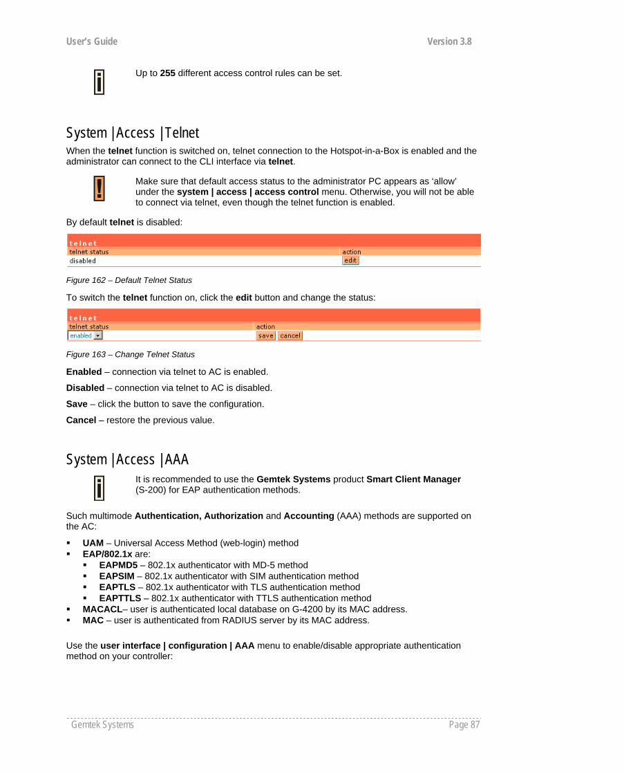
User’s Guide Version 3.8
Gemtek Systems Page 87
Up to 255 different access control rules can be set.
System | Access | Telnet When the telnet function is switched on, telnet connection to the Hotspot-in-a-Box is enabled and the administrator can connect to the CLI interface via telnet.
Make sure that default access status to the administrator PC appears as ‘allow’ under the system | access | access control menu. Otherwise, you will not be able to connect via telnet, even though the telnet function is enabled.
By default telnet is disabled:
Figure 162 – Default Telnet Status
To switch the telnet function on, click the edit button and change the status:
Figure 163 – Change Telnet Status
Enabled – connection via telnet to AC is enabled.
Disabled – connection via telnet to AC is disabled.
Save – click the button to save the configuration.
Cancel – restore the previous value.
System | Access | AAA
It is recommended to use the Gemtek Systems product Smart Client Manager (S-200) for EAP authentication methods.
Such multimode Authentication, Authorization and Accounting (AAA) methods are supported on the AC:
UAM – Universal Access Method (web-login) method EAP/802.1x are:
EAPMD5 – 802.1x authenticator with MD-5 method EAPSIM – 802.1x authenticator with SIM authentication method EAPTLS – 802.1x authenticator with TLS authentication method EAPTTLS – 802.1x authenticator with TTLS authentication method
MACACL– user is authenticated local database on G-4200 by its MAC address. MAC – user is authenticated from RADIUS server by its MAC address.
Use the user interface | configuration | AAA menu to enable/disable appropriate authentication method on your controller:

User’s Guide Version 3.8
Gemtek Systems Page 88
Figure 164 – AAA Settings
If UAM (web-login) method is disabled the subscriber will not be able to login through the web interface.
Status – change status of selected AAA method [enabled/disabled].
For MAC-RADIUS authentication the following settings are required:
Figure 165 – MAC-RADIUS Authentication
Use Password – select [RADIUS secret] or [User defined] password for user authenticating by its MAC address.
Password – enter password with user-defined option selected. Password will be one for all users authenticated by MAC address [string, 4-32 characters, no spaces allowed].
Current RADIUS secret value is only displayed and CANNOT be changed under the AAA menu. To change the RADIUS secret value use the network interface | RADIUS | servers menu.
For MAC-ACL authentication, G-4200 will use the local MAC address database, which can be configured on system | Access | MAC List.
System | Access | UAT With Universal Address Translation (UAT) enabled, the Hotspot-in-a-Box will automatically and transparently translate fixed IP settings (IP address, gateway, DNS, proxy server) on a user’s PC so that he can connect to the broadband Internet service. There is no need for end-users to reset their corporate IP or web settings. Also outgoing subscriber e-mails can be redirected to the operator's e-mail server in order to facilitate e-mail forwarding for foreign subscribers.
Universal address translation works only on LAN and VLAN interfaces with authentication setting enabled (see more about these settings in the System | Access | NAV).
The Universal Address Translation (UAT) function can be enabled using the system | access | UAT menu.
Figure 166 – Universal Address Translation Settings
To change UAT settings on interface click the edit button in the action column. The status can be changed now:

User’s Guide Version 3.8
Gemtek Systems Page 89
Figure 167 – Change Universal Address Translation Status
G-4200 current support 50 UAT clients simultaneously.
System | Access | Isolation Isolation mechanism under the system | access | isolation menu increases the security of the AC users.
Figure 168 – Isolation
Bindmac – with bindmac function enabled, the AC binds the user’s MAC and IP addresses together after a successful logon by the wireless client and thereby preventing Internet access to a new user who uses the same client IP address, although be it with a different MAC address [enabled/disabled]. Isolation – enable this function to prevent users on the same LAN to communicate with each other. Users can communicate only through the AC [enabled/disabled].
System | Access | NAV To change visitor access on different LANs or VLANs, authentication or NAT attributes for AC users, go to the system | access | NAV menu:
Figure 169 – NAT, Authentication and Visitor Access
Interface – interface on which the changes will be done [ixp0, non editable].
IP Address – IP address of interface [non editable].
NAT – network address translation service status [enabled/disabled]. If enabled, users can access the Internet under its network gateway address.
Authentication – with disabled authentication, the user from his LAN gets access to the Internet without any authentication. If enabled, authentication for Internet access is required for all users [enabled/disabled].
This setting is important when configuring the UAT. See section: System | Access | UAT for more details.
Visitor Access – client with specific WISPr attribute can reach the LAN with enabled visitor access [enabled/disabled] (see more details about visitor access below).
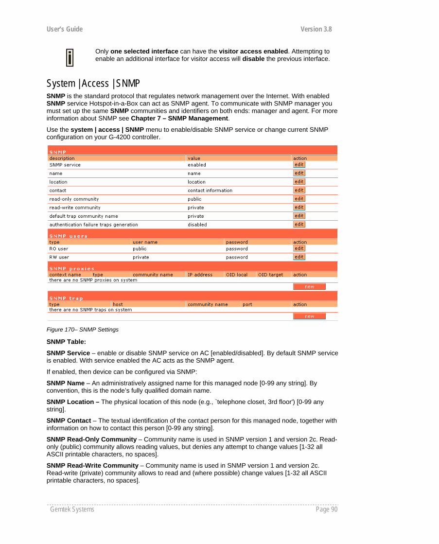
User’s Guide Version 3.8
Gemtek Systems Page 90
Only one selected interface can have the visitor access enabled. Attempting to enable an additional interface for visitor access will disable the previous interface.
System | Access | SNMP SNMP is the standard protocol that regulates network management over the Internet. With enabled SNMP service Hotspot-in-a-Box can act as SNMP agent. To communicate with SNMP manager you must set up the same SNMP communities and identifiers on both ends: manager and agent. For more information about SNMP see Chapter 7 – SNMP Management.
Use the system | access | SNMP menu to enable/disable SNMP service or change current SNMP configuration on your G-4200 controller.
Figure 170– SNMP Settings
SNMP Table:
SNMP Service – enable or disable SNMP service on AC [enabled/disabled]. By default SNMP service is enabled. With service enabled the AC acts as the SNMP agent.
If enabled, then device can be configured via SNMP:
SNMP Name – An administratively assigned name for this managed node [0-99 any string]. By convention, this is the node’s fully qualified domain name.
SNMP Location – The physical location of this node (e.g., `telephone closet, 3rd floor') [0-99 any string].
SNMP Contact – The textual identification of the contact person for this managed node, together with information on how to contact this person [0-99 any string].
SNMP Read-Only Community – Community name is used in SNMP version 1 and version 2c. Read-only (public) community allows reading values, but denies any attempt to change values [1-32 all ASCII printable characters, no spaces].
SNMP Read-Write Community – Community name is used in SNMP version 1 and version 2c. Read-write (private) community allows to read and (where possible) change values [1-32 all ASCII printable characters, no spaces].
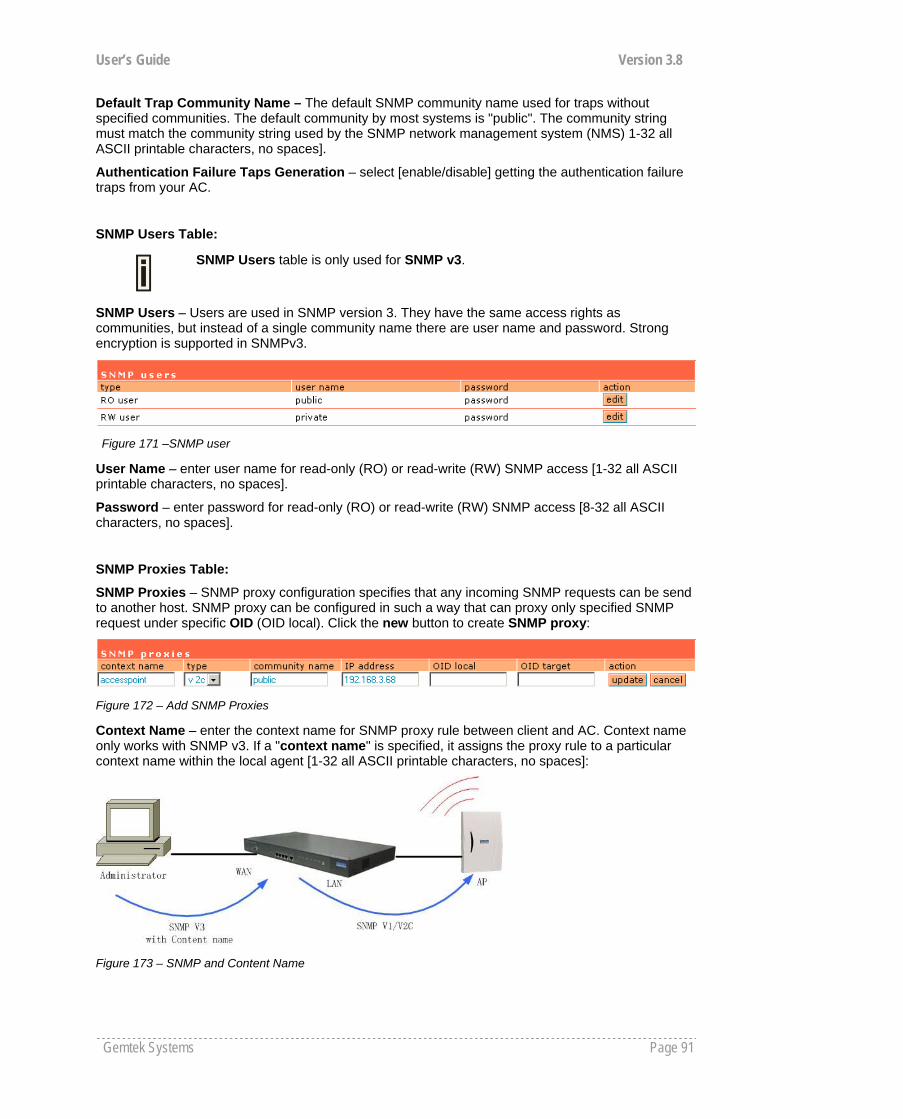
User’s Guide Version 3.8
Gemtek Systems Page 91
Default Trap Community Name – The default SNMP community name used for traps without specified communities. The default community by most systems is "public". The community string must match the community string used by the SNMP network management system (NMS) 1-32 all ASCII printable characters, no spaces].
Authentication Failure Taps Generation – select [enable/disable] getting the authentication failure traps from your AC.
SNMP Users Table:
SNMP Users table is only used for SNMP v3.
SNMP Users – Users are used in SNMP version 3. They have the same access rights as communities, but instead of a single community name there are user name and password. Strong encryption is supported in SNMPv3.
Figure 171 –SNMP user
User Name – enter user name for read-only (RO) or read-write (RW) SNMP access [1-32 all ASCII printable characters, no spaces].
Password – enter password for read-only (RO) or read-write (RW) SNMP access [8-32 all ASCII characters, no spaces].
SNMP Proxies Table:
SNMP Proxies – SNMP proxy configuration specifies that any incoming SNMP requests can be send to another host. SNMP proxy can be configured in such a way that can proxy only specified SNMP request under specific OID (OID local). Click the new button to create SNMP proxy:
Figure 172 – Add SNMP Proxies
Context Name – enter the context name for SNMP proxy rule between client and AC. Context name only works with SNMP v3. If a "context name" is specified, it assigns the proxy rule to a particular context name within the local agent [1-32 all ASCII printable characters, no spaces]:
Figure 173 – SNMP and Content Name

User’s Guide Version 3.8
Gemtek Systems Page 92
This is the proper way to query multiple SNMP agents through a single proxy. Assign each remote agent to a different context name. Then you can use "snmpwalk -n contextname1" to walk one remote proxied agent and "snmpwalk -n contextname2" to walk another, assuming you are using SNMPv3 to talk to the proxy (snmpv1 and snmpv2c context mappings aren’t currently supported but might be in the future) (see the Figure 173 – SNMP and Content Name).
Type – select SNMP version for SNMP proxy rule between AP and AC [v1/v2c].
Community Name – enter community name for communicating with the host (see Figure 173 – SNMP and Content Name, the host is AP in this case) [1-32 all ASCII printable characters, no spaces].
IP Address – specify the host address (AP in our case) to which any incoming requests should be re-sent [dots and digits].
OID Local – enter Object Identifier (OID) of MIB tree if you want to proxy only the specified SNMP requests under the specific OID in the MIB tree. That part is specified by OID local tree [optional, number and dots].
OID Target – Optionally, you can relocate the "OID local” tree to the new location at the "OID target"
If no OID is specified all SNMP request to the controller will be redirected to a specific host.
SNMP Trap Table:
You can configure your SNMP agent to send SNMP Traps (and/or inform notifications) under the defined host (SNMP manager) and community name (optional).
Figure 174 – SNMP Trap Table
Type – select trap message type [v1/v2/inform].
Host – enter SNMP manager IP address [dots and digits].
Community Name – specify the community name at a SNMP trap message. This community will be used in trap messages to authenticate the SNMP manager. If not defined, the default trap community name will be used (specified in the SNMP table) [1-32 all ASCII printable characters, no spaces].
Port – enter the port number the trap messages should be send through [number].
System | Access | Web Auth Web auth controls all the built-in AAA web authentication method.
Figure 175 – Web Authentication methods
IP: IP authentication method. it means every client who has an IP address can be authenticated. Before client authentication, its first web access of client will be redirected to a confirm/login page, Need not any username or password, user just press confirm or OK button then client will be automatically authenticated and client‘s MAC address will be act as the username of login session.
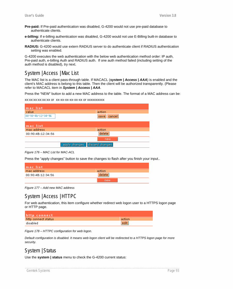
User’s Guide Version 3.8
Gemtek Systems Page 93
Pre-paid: If Pre-paid authentication was disabled, G-4200 would not use pre-paid database to authenticate clients.
e-billing: If e-billing authentication was disabled, G-4200 would not use E-Billing built-in database to authenticate clients.
RADIUS: G-4200 would use extern RADIUS server to do authenticate client if RADIUS authentication setting was enabled.
G-4200 executes the web authentication with the below web authentication method order: IP auth, Pre-paid auth, e-billing Auth and RADIUS auth. If one auth method failed (including setting of the auth method is disabled), try next.
System | Access | Mac List The MAC list is a client pass-through table. If MACACL (system | Access | AAA) is enabled and the client’s MAC address is belong to this table. Then the client will be authorized transparently. (Please refer to MACACL item in System | Access | AAA.
Press the “NEW” button to add a new MAC address to the table. The format of a MAC address can be:
xx:xx:xx:xx:xx:xx or xx-xx-xx-xx-xx-xx or xxxxxxxxxx
Figure 176 – MAC List for MAC-ACL
Press the “apply changes” button to save the changes to flash after you finish your input..
Figure 177 – Add new MAC address
System | Access | HTTPC For web authentication, this item configure whether redirect web logon user to a HTTPS logon page or HTTP page.
Figure 178 – HTTPC configuration for web logon.
Default configuration is disabled. It means web logon client will be redirected to a HTTPS logon page for more security.
System | Status Use the system | status menu to check the G-4200 current status:

User’s Guide Version 3.8
Gemtek Systems Page 94
Device statistics (including device name, model, firmware version, status, logged administrators, general uptime, memory, load, connected clients)
Figure 179 – Device Statistics
Device Name – full device name and model.
Firmware Version – the current version of the firmware.
Device Status – current device status: running/warning.
Currently Connected Administrators – logged administrators list in format: [administrator name, IP address, and idling time in hours/minutes/seconds].
Uptime – indicates the time, expressed in days, hours and minutes since the system was last rebooted [days/hours/minutes/seconds].
Software Runtime – indicates the time, expressed in days, hours and minutes since the software reboot. The system itself can restart the software without rebooting the device [days/hours/minutes/seconds].
Total Memory – total operational memory of your G-4200 [kB].
Free Memory – indicates the memory currently available in the controller [kB].
Average Load – indicates the average load of the G-4200 processor in the period of the last 1minute, 5 minutes and 15 minutes (a larger value means a larger average load on the processor).
Minimum load – 0.0 Normal load – should not exceed 1.0 (including) Processor is busy – more than 1.00.
Connected Clients Number – total number of current connected clients on LAN interface. Click on the settings and get detailed connected clients list (clients page under the connection | user):
Figure 180 – Connected Clients Detailed List
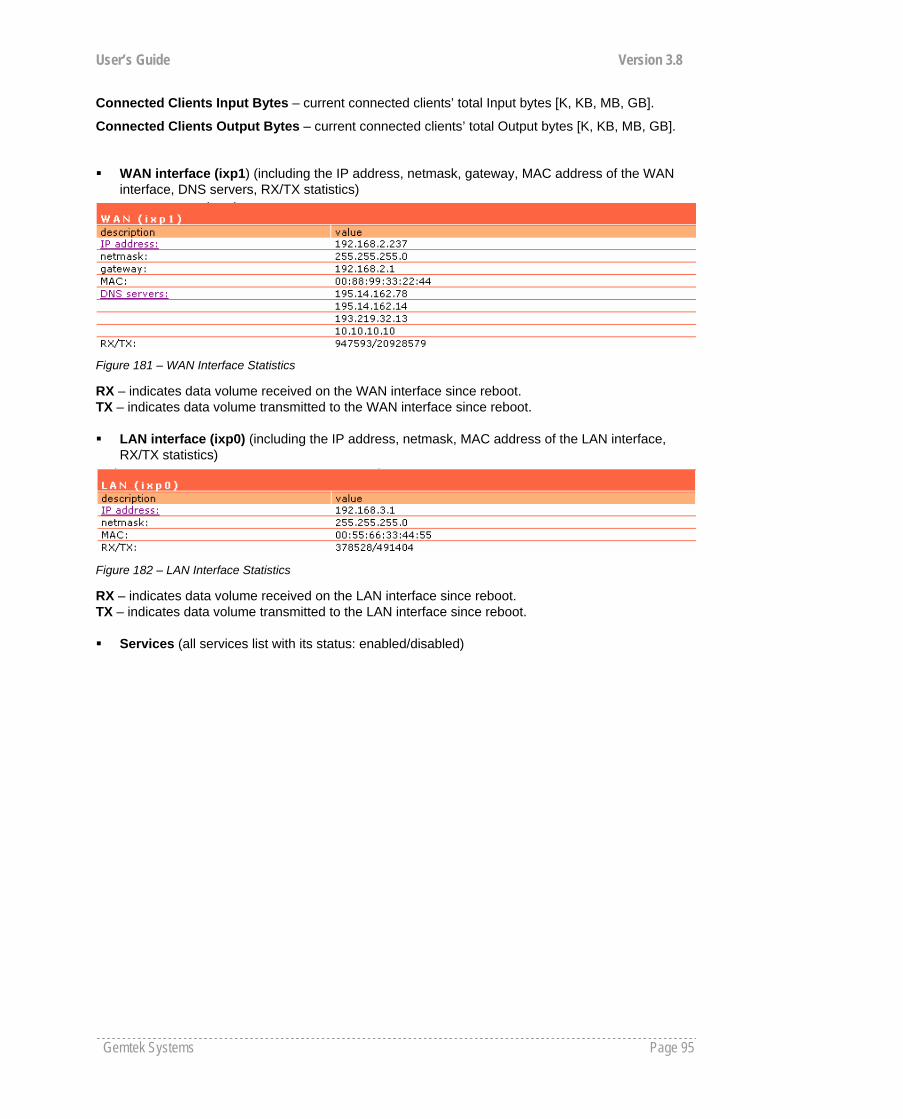
User’s Guide Version 3.8
Gemtek Systems Page 95
Connected Clients Input Bytes – current connected clients’ total Input bytes [K, KB, MB, GB].
Connected Clients Output Bytes – current connected clients’ total Output bytes [K, KB, MB, GB].
WAN interface (ixp1) (including the IP address, netmask, gateway, MAC address of the WAN interface, DNS servers, RX/TX statistics)
Figure 181 – WAN Interface Statistics
RX – indicates data volume received on the WAN interface since reboot. TX – indicates data volume transmitted to the WAN interface since reboot. LAN interface (ixp0) (including the IP address, netmask, MAC address of the LAN interface,
RX/TX statistics)
Figure 182 – LAN Interface Statistics
RX – indicates data volume received on the LAN interface since reboot. TX – indicates data volume transmitted to the LAN interface since reboot. Services (all services list with its status: enabled/disabled)
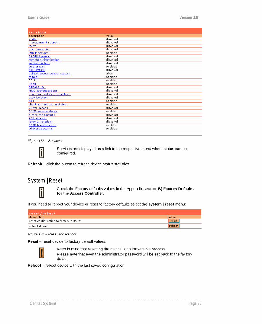
User’s Guide Version 3.8
Gemtek Systems Page 96
Figure 183 – Services
Services are displayed as a link to the respective menu where status can be configured.
Refresh – click the button to refresh device status statistics.
System | Reset
Check the Factory defaults values in the Appendix section: B) Factory Defaults for the Access Controller.
If you need to reboot your device or reset to factory defaults select the system | reset menu:
Figure 184 – Reset and Reboot
Reset – reset device to factory default values.
Keep in mind that resetting the device is an irreversible process. Please note that even the administrator password will be set back to the factory default.
Reboot – reboot device with the last saved configuration.
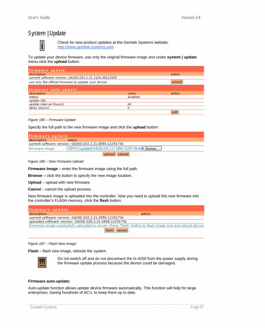
User’s Guide Version 3.8
Gemtek Systems Page 97
System | Update
Check for new product updates at the Gemtek Systems website: http://www.gemtek-systems.com
To update your device firmware, use only the original firmware image and under system | update menu click the upload button:
Figure 185 – Firmware Update
Specify the full path to the new firmware image and click the upload button:
Figure 186 – New Firmware Upload
Firmware Image – enter the firmware image using the full path.
Browse – click the button to specify the new image location.
Upload – upload with new firmware.
Cancel – cancel the upload process.
New firmware image is uploaded into the controller. Now you need to upload this new firmware into the controller’s FLASH memory, click the flash button:
Figure 187 – Flash New Image
Flash – flash new image, reboots the system.
Do not switch off and do not disconnect the G-4200 from the power supply during the firmware update process because the device could be damaged.
Firmware auto-update:
Auto-update function allows update device firmware automatically. This function will help for large enterprises, having hundreds of AC's, to keep them up to date.
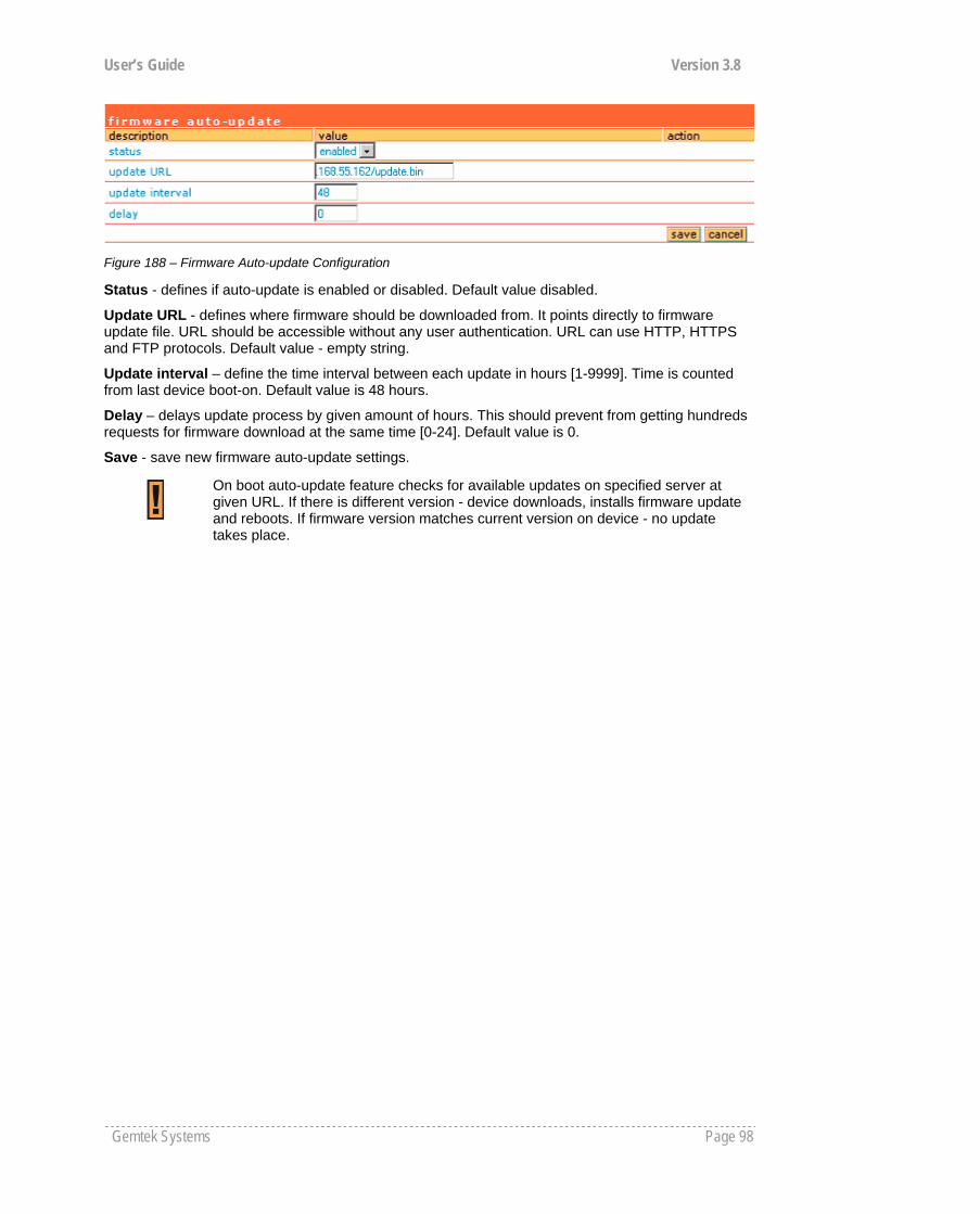
User’s Guide Version 3.8
Gemtek Systems Page 98
Figure 188 – Firmware Auto-update Configuration
Status - defines if auto-update is enabled or disabled. Default value disabled.
Update URL - defines where firmware should be downloaded from. It points directly to firmware update file. URL should be accessible without any user authentication. URL can use HTTP, HTTPS and FTP protocols. Default value - empty string.
Update interval – define the time interval between each update in hours [1-9999]. Time is counted from last device boot-on. Default value is 48 hours.
Delay – delays update process by given amount of hours. This should prevent from getting hundreds requests for firmware download at the same time [0-24]. Default value is 0.
Save - save new firmware auto-update settings.
On boot auto-update feature checks for available updates on specified server at given URL. If there is different version - device downloads, installs firmware update and reboots. If firmware version matches current version on device - no update takes place.
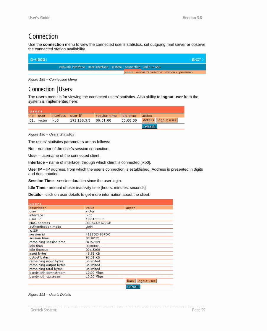
User’s Guide Version 3.8
Gemtek Systems Page 99
Connection Use the connection menu to view the connected user’s statistics, set outgoing mail server or observe the connected station availability.
Figure 189 – Connection Menu
Connection | Users The users menu is for viewing the connected users’ statistics. Also ability to logout user from the system is implemented here:
Figure 190 – Users’ Statistics
The users’ statistics parameters are as follows:
No – number of the user’s session connection.
User – username of the connected client.
Interface – name of interface, through which client is connected [ixp0].
User IP – IP address, from which the user’s connection is established. Address is presented in digits and dots notation.
Session Time - session duration since the user login.
Idle Time - amount of user inactivity time [hours: minutes: seconds].
Details – click on user details to get more information about the client:
Figure 191 – User’s Details
User’s Guide Version 3.8
Gemtek Systems Page 100
User – the username of the connected client.
Interface – name of interface, through which client is connected.
User IP – IP address, from which the user’s connection is established. Address is presented in digits and dots notation.
MAC Address – hardware address of the network device from which the user is connected.
Authentication mode – authentication method which user uses to connect.
WISP – WISP domain name where the user belongs.
Session ID – the unique user’s session ID number. This can be used for troubleshooting purposes.
Session Time – session time duration since user login [hours: minutes: seconds/unlimited].
Remaining Time – remaining user’s session time [hours: minutes: seconds/unlimited]. Session time for user is defined in the RADIUS server.
Idle Time - amount of user inactivity time [hours: minutes: seconds].
Input Bytes - amount of data in bytes, which the user network device has received [Bytes].
Output Bytes - amount of data in bytes, transmitted by the user network device [Bytes].
Remaining input/output/total bytes – user session remaining input/output bytes. WISP Operator can define the user session in bytes. Remaining bytes is received from RADIUS [Bytes/unlimited].
Bandwidth downstream/upstream – user upstream and downstream bandwidth [in bps].
Back – returns to connected client’s statistics list.
Logout User – click this button to explicitly logout user from the network.
Refresh – click the button to refresh users’ statistics.
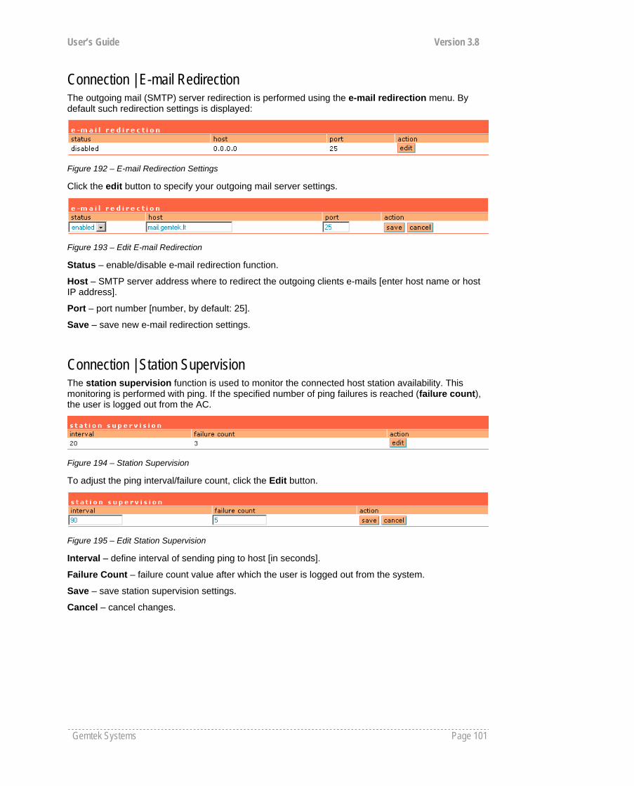
User’s Guide Version 3.8
Gemtek Systems Page 101
Connection | E-mail Redirection The outgoing mail (SMTP) server redirection is performed using the e-mail redirection menu. By default such redirection settings is displayed:
Figure 192 – E-mail Redirection Settings
Click the edit button to specify your outgoing mail server settings.
Figure 193 – Edit E-mail Redirection
Status – enable/disable e-mail redirection function.
Host – SMTP server address where to redirect the outgoing clients e-mails [enter host name or host IP address].
Port – port number [number, by default: 25].
Save – save new e-mail redirection settings.
Connection | Station Supervision The station supervision function is used to monitor the connected host station availability. This monitoring is performed with ping. If the specified number of ping failures is reached (failure count), the user is logged out from the AC.
Figure 194 – Station Supervision
To adjust the ping interval/failure count, click the Edit button.
Figure 195 – Edit Station Supervision
Interval – define interval of sending ping to host [in seconds].
Failure Count – failure count value after which the user is logged out from the system.
Save – save station supervision settings.
Cancel – cancel changes.
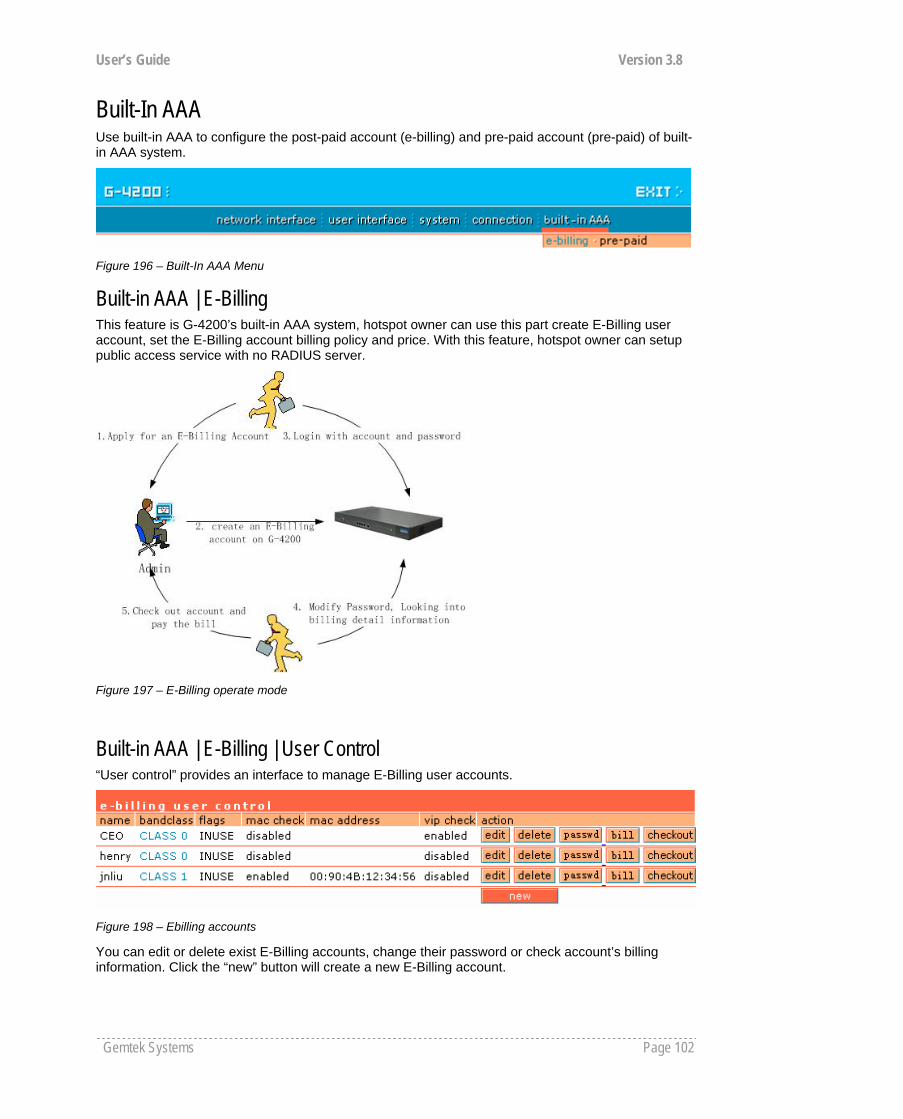
User’s Guide Version 3.8
Gemtek Systems Page 102
Built-In AAA Use built-in AAA to configure the post-paid account (e-billing) and pre-paid account (pre-paid) of built-in AAA system.
Figure 196 – Built-In AAA Menu
Built-in AAA | E-Billing This feature is G-4200’s built-in AAA system, hotspot owner can use this part create E-Billing user account, set the E-Billing account billing policy and price. With this feature, hotspot owner can setup public access service with no RADIUS server.
Figure 197 – E-Billing operate mode
Built-in AAA | E-Billing | User Control “User control” provides an interface to manage E-Billing user accounts.
Figure 198 – Ebilling accounts
You can edit or delete exist E-Billing accounts, change their password or check account’s billing information. Click the “new” button will create a new E-Billing account.
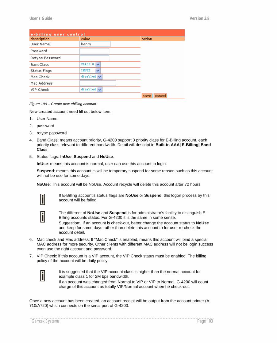
User’s Guide Version 3.8
Gemtek Systems Page 103
Figure 199 – Create new ebilling account
New created account need fill out below item:
1. User Name
2. password
3. retype password
4. Band Class: means account priority, G-4200 support 3 priority class for E-Billing account, each priority class relevant to different bandwidth. Detail will descript in Built-in AAA| E-Billing| Band Class
5. Status flags: InUse, Suspend and NoUse.
InUse: means this account is normal, user can use this account to login.
Suspend: means this account is will be temporary suspend for some reason such as this account will not be use for some days.
NoUse: This account will be NoUse. Account recycle will delete this account after 72 hours.
6. Mac check and Mac address: If “Mac Check” is enabled, means this account will bind a special MAC address for more security. Other clients with different MAC address will not be login success even use the right account and password.
7. VIP Check: if this account is a VIP account, the VIP Check status must be enabled. The billing policy of the account will be daily policy.
Once a new account has been created, an account receipt will be output from the account printer (A-710/A720) which connects on the serial port of G-4200.
The different of NoUse and Suspend is for administrator’s facility to distinguish E-Billing accounts status. For G-4200 it is the same in some sense. Suggestion: If an account is check-out, better change the account status to NoUse and keep for some days rather than delete this account to for user re-check the account detail.
If E-Billing account’s status flags are NoUse or Suspend, this logon process by this account will be failed.
It is suggested that the VIP account class is higher than the normal account for example class 1 for 2M bps bandwidth. If an account was changed from Normal to VIP or VIP to Normal, G-4200 will count charge of this account as totally VIP/Normal account when he check-out.
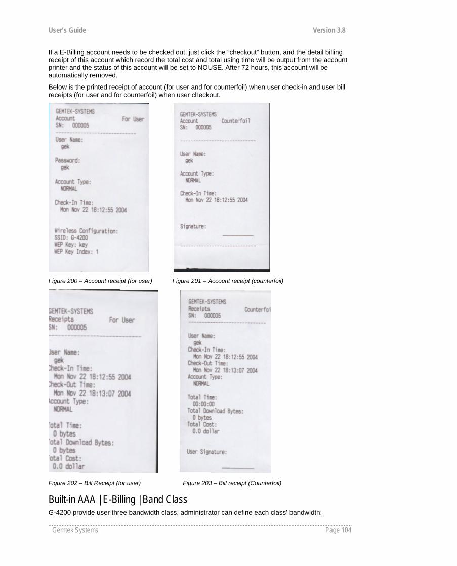
User’s Guide Version 3.8
Gemtek Systems Page 104
If a E-Billing account needs to be checked out, just click the “checkout” button, and the detail billing receipt of this account which record the total cost and total using time will be output from the account printer and the status of this account will be set to NOUSE. After 72 hours, this account will be automatically removed.
Below is the printed receipt of account (for user and for counterfoil) when user check-in and user bill receipts (for user and for counterfoil) when user checkout.
Figure 200 – Account receipt (for user) Figure 201 – Account receipt (counterfoil)
Figure 202 – Bill Receipt (for user) Figure 203 – Bill receipt (Counterfoil)
Built-in AAA | E-Billing | Band Class G-4200 provide user three bandwidth class, administrator can define each class’ bandwidth:

User’s Guide Version 3.8
Gemtek Systems Page 105
Figure 204 – Bandwidth class
As the figure 195 descript, E-Billing account with class 0 will has only 1M bandwidth for download and upload while class 2 account will has 4M bandwidth for both download and upload.
Built-in AAA | E-Billing | Bill setting Administrator set the E-Billing billing policy through this sub-menu:
Figure 205 – Bill setting
G-4200 supports billing policy of billing by Hour, by Data flow and by hour with ceiling policy. Administrator need fill a price of each billing unit; the price can be accuracy to two places of decimals. For time the unit is hour and for data it is Mbytes.
If the “By hour with ceiling” policy is selected, the daily cost of an account will be limit to the ceiling cost, (PM12:00 as the start time and ending time of one day).
In “Charge Unit” administrator need fill out the currency unit of the local country.
Administrator and logon user can look into user’s detail billing list:
Figure 206 – Bill detail of an ebilling account
“Start time” means the time when user start this session.
“Session time” means the total time of this session.
“Download bytes” and “upload bytes” means the flow of this session.
G-4200 will only compute the download data flow if the policy is billing by data flow.
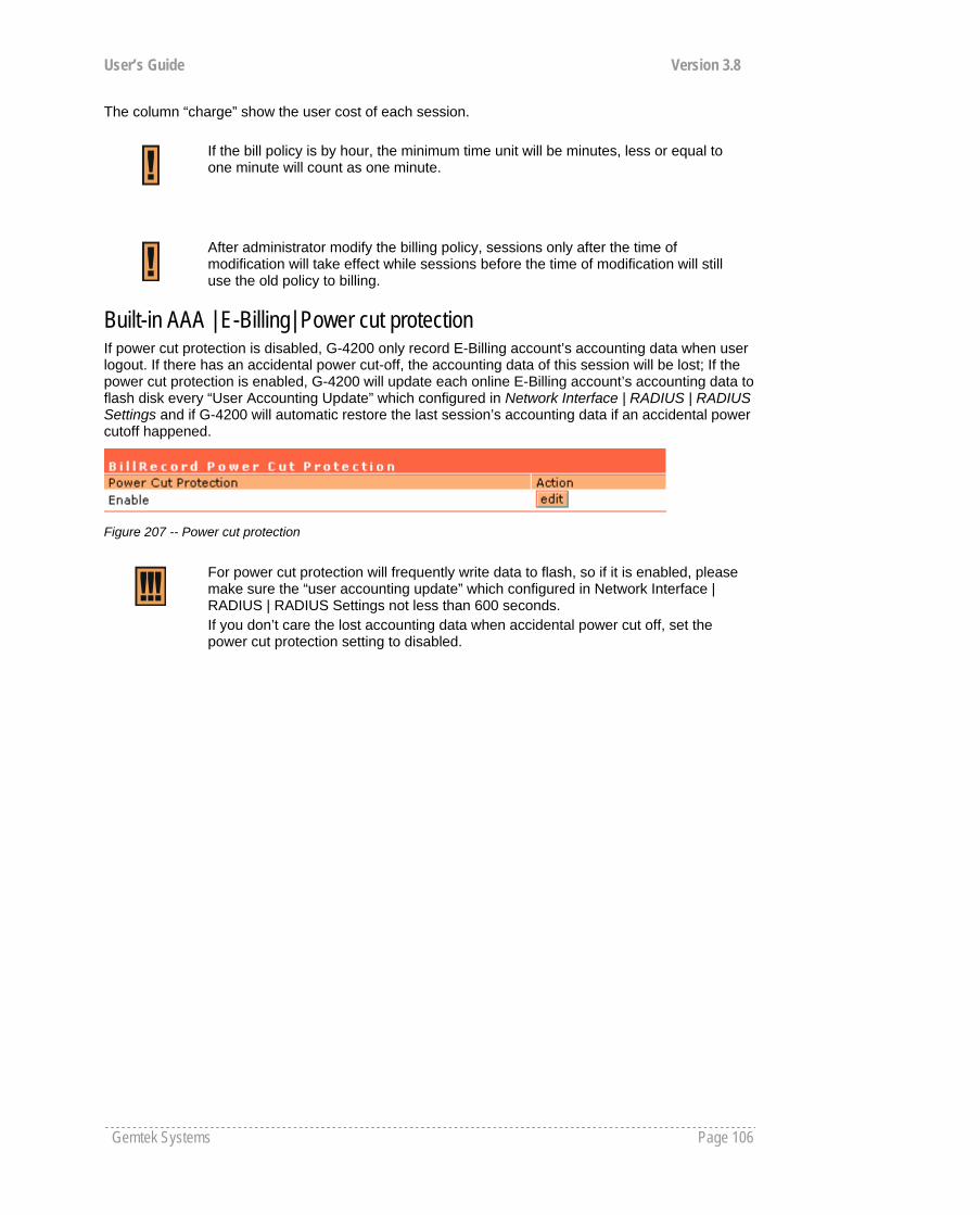
User’s Guide Version 3.8
Gemtek Systems Page 106
The column “charge” show the user cost of each session.
Built-in AAA | E-Billing| Power cut protection If power cut protection is disabled, G-4200 only record E-Billing account’s accounting data when user logout. If there has an accidental power cut-off, the accounting data of this session will be lost; If the power cut protection is enabled, G-4200 will update each online E-Billing account’s accounting data to flash disk every “User Accounting Update” which configured in Network Interface | RADIUS | RADIUS Settings and if G-4200 will automatic restore the last session’s accounting data if an accidental power cutoff happened.
Figure 207 -- Power cut protection
If the bill policy is by hour, the minimum time unit will be minutes, less or equal to one minute will count as one minute.
After administrator modify the billing policy, sessions only after the time of modification will take effect while sessions before the time of modification will still use the old policy to billing.
For power cut protection will frequently write data to flash, so if it is enabled, please make sure the “user accounting update” which configured in Network Interface | RADIUS | RADIUS Settings not less than 600 seconds. If you don’t care the lost accounting data when accidental power cut off, set the power cut protection setting to disabled.
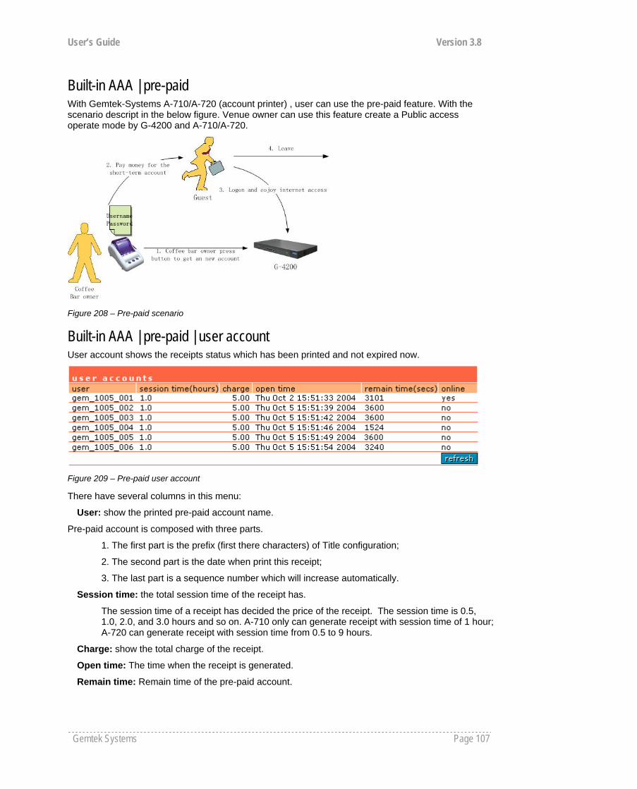
User’s Guide Version 3.8
Gemtek Systems Page 107
Built-in AAA | pre-paid With Gemtek-Systems A-710/A-720 (account printer) , user can use the pre-paid feature. With the scenario descript in the below figure. Venue owner can use this feature create a Public access operate mode by G-4200 and A-710/A-720.
Figure 208 – Pre-paid scenario
Built-in AAA | pre-paid | user account User account shows the receipts status which has been printed and not expired now.
Figure 209 – Pre-paid user account
There have several columns in this menu:
User: show the printed pre-paid account name.
Pre-paid account is composed with three parts.
1. The first part is the prefix (first there characters) of Title configuration;
2. The second part is the date when print this receipt;
3. The last part is a sequence number which will increase automatically.
Session time: the total session time of the receipt has.
The session time of a receipt has decided the price of the receipt. The session time is 0.5, 1.0, 2.0, and 3.0 hours and so on. A-710 only can generate receipt with session time of 1 hour; A-720 can generate receipt with session time from 0.5 to 9 hours.
Charge: show the total charge of the receipt.
Open time: The time when the receipt is generated.
Remain time: Remain time of the pre-paid account.
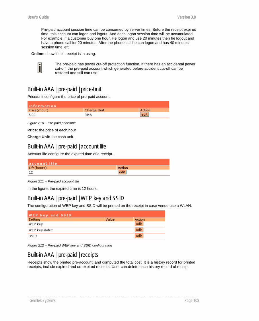
User’s Guide Version 3.8
Gemtek Systems Page 108
Pre-paid account session time can be consumed by server times. Before the receipt expired time, this account can logon and logout. And each logon session time will be accumulated. For example, if a customer buy one hour. He logon and use 20 minutes then he logout and have a phone call for 20 minutes. After the phone call he can logon and has 40 minutes session time left.
Online: show if this receipt is in using.
Built-in AAA | pre-paid | price/unit Price/unit configure the price of pre-paid account.
Figure 210 – Pre-paid price/unit
Price: the price of each hour
Charge Unit: the cash unit.
Built-in AAA | pre-paid | account life Account life configure the expired time of a receipt.
Figure 211 – Pre-paid account life
In the figure, the expired time is 12 hours.
Built-in AAA | pre-paid | WEP key and SSID The configuration of WEP key and SSID will be printed on the receipt in case venue use a WLAN.
Figure 212 – Pre-paid WEP key and SSID configuration
Built-in AAA | pre-paid | receipts Receipts show the printed pre-account, and computed the total cost. It is a history record for printed receipts, include expired and un-expired receipts. User can delete each history record of receipt.
The pre-paid has power cut-off protection function. If there has an accidental power cut-off, the pre-paid account which generated before accident cut-off can be restored and still can use.
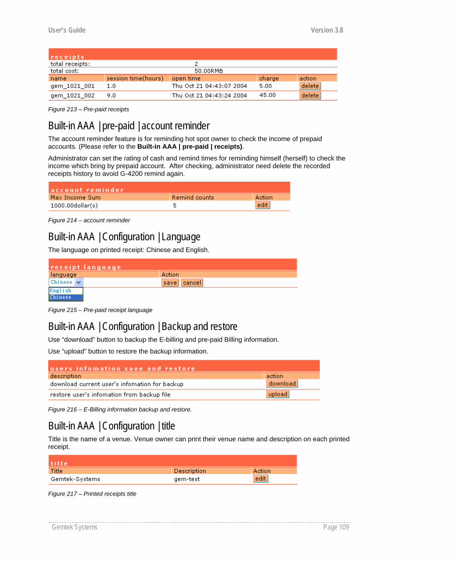
User’s Guide Version 3.8
Gemtek Systems Page 109
Figure 213 – Pre-paid receipts
Built-in AAA | pre-paid | account reminder The account reminder feature is for reminding hot spot owner to check the income of prepaid accounts. (Please refer to the Built-in AAA | pre-paid | receipts).
Administrator can set the rating of cash and remind times for reminding himself (herself) to check the income which bring by prepaid account. After checking, administrator need delete the recorded receipts history to avoid G-4200 remind again.
Figure 214 – account reminder
Built-in AAA | Configuration | Language The language on printed receipt: Chinese and English.
Figure 215 – Pre-paid receipt language
Built-in AAA | Configuration | Backup and restore Use “download” button to backup the E-billing and pre-paid Billing information.
Use “upload” button to restore the backup information.
Figure 216 – E-Billing information backup and restore.
Built-in AAA | Configuration | title Title is the name of a venue. Venue owner can print their venue name and description on each printed receipt.
Figure 217 – Printed receipts title
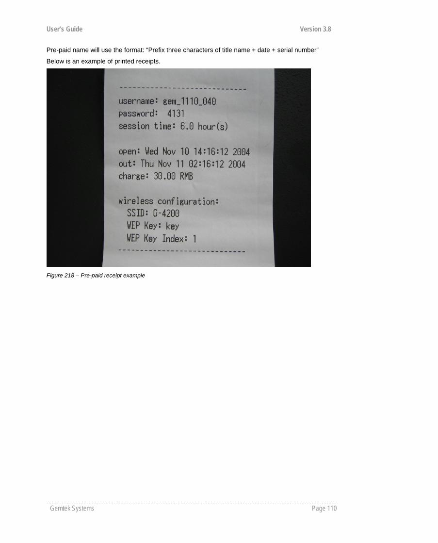
User’s Guide Version 3.8
Gemtek Systems Page 110
Pre-paid name will use the format: “Prefix three characters of title name + date + serial number”
Below is an example of printed receipts.
Figure 218 – Pre-paid receipt example

User’s Guide Version 3.8
Gemtek Systems Page 111
A) Access Controller Specification Technical Data Network and Hotspot Access Control IP Router with NAT/PAT, firewall filters Hotspot access controller with web browser log-
on (UAM) and 802.1x/EAP support, Smart Client support, MAC authentication, WISPr compliant (Wi-Fi alliance)
AAA RADIUS client and proxy server with EAP support
Universal access method (web browser log-on) with XML support and walled garden (free web sites)
Universal address translation and web proxy support (any client configuration is accepted)
WISPr compatible log-on via web browser, SSL/TLS support UAT
VPN client (GRE) IEEE 802.1x authenticator with EAP-SIM, MD-5, TLS, TTLS, PEAP
WPA support DHCP server, DHCP relay gateway, DHCP client VPN pass-through Layer 2 user isolation E-mail redirection Bandwidth management via RADIUS
Interface WAN 10/100Mb Ethernet, auto sensing, RJ-45 LAN Four 10/100Mb Ethernet port switched, auto sensing, RJ-45, 802.1q
VLAN support Management
Interfaces HTTPs, Telnet, SNMP (MIB II, Ethernet MIB, bridge MIB, private MIB), Terminal
Software Update Remote software update via HTTPs Reset Remote reset / Manufacturing reset Physical Specification Dimension 436 mm x 260 mm x 44 mm Weight - Environment Specification Temperature Humidity Operating 0 to 45°C 10 % to 90%, non-condensing Power Supply Input 100-230V AC, 50/60Hz LEDs 7 LEDs Power, Online, WAN link, 4x LAN-link Warranty 2 years Package Contents G-4200 SMB Public Access Controller Mounting Kit
Appendix
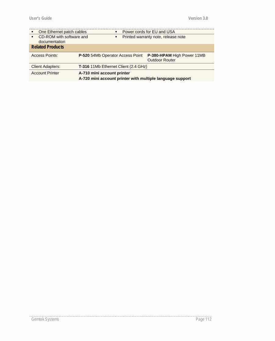
User’s Guide Version 3.8
Gemtek Systems Page 112
One Ethernet patch cables Power cords for EU and USA CD-ROM with software and
documentation Printed warranty note, release note
Related Products Access Points: P-520 54Mb Operator Access Point P-380-HPAM High Power 11MB
Outdoor Router Client Adapters: T-316 11Mb Ethernet Client (2.4 GHz) Account Printer A-710 mini account printer
A-720 mini account printer with multiple language support
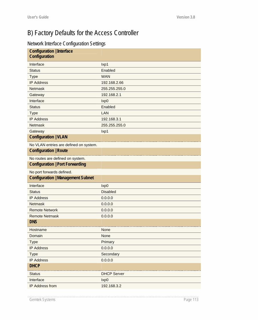
User’s Guide Version 3.8
Gemtek Systems Page 113
B) Factory Defaults for the Access Controller Network Interface Configuration Settings Configuration | Interface Configuration
Interface Ixp1 Status Enabled Type WAN IP Address 192.168.2.66 Netmask 255.255.255.0 Gateway 192.168.2.1 Interface Ixp0 Status Enabled Type LAN IP Address 192.168.3.1 Netmask 255.255.255.0 Gateway Ixp1 Configuration | VLAN No VLAN entries are defined on system. Configuration | Route No routes are defined on system. Configuration | Port Forwarding No port forwards defined. Configuration | Management Subnet Interface Ixp0 Status Disabled IP Address 0.0.0.0 Netmask 0.0.0.0 Remote Network 0.0.0.0 Remote Netmask 0.0.0.0 DNS
Hostname None Domain None Type Primary IP Address 0.0.0.0 Type Secondary IP Address 0.0.0.0 DHCP
Status DHCP Server Interface Ixp0 IP Address from 192.168.3.2
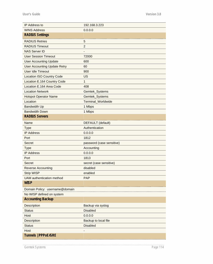
User’s Guide Version 3.8
Gemtek Systems Page 114
IP Address to 192.168.3.223 WINS Address 0.0.0.0 RADIUS Settings
RADIUS Retries 5 RADIUS Timeout 2 NAS Server ID - User Session Timeout 72000 User Accounting Update 600 User Accounting Update Retry 60 User Idle Timeout 900 Location ISO Country Code US Location E.164 Country Code 1 Location E.164 Area Code 408 Location Network Gemtek_Systems Hotspot Operator Name Gemtek_Systems Location Terminal_Worldwide Bandwidth Up 1 Mbps Bandwidth Down 1 Mbps RADIUS Servers
Name DEFAULT (default) Type Authentication IP Address 0.0.0.0 Port 1812 Secret password (case sensitive) Type Accounting IP Address 0.0.0.0 Port 1813 Secret secret (case sensitive) Reverse Accounting disabled Strip WISP enabled UAM authentication method PAP WISP
Domain Policy: username@domain No WISP defined on system Accounting Backup Description Backup via syslog Status Disabled Host 0.0.0.0 Description Backup to local file Status Disabled Host - Tunnels | PPPoE/GRE
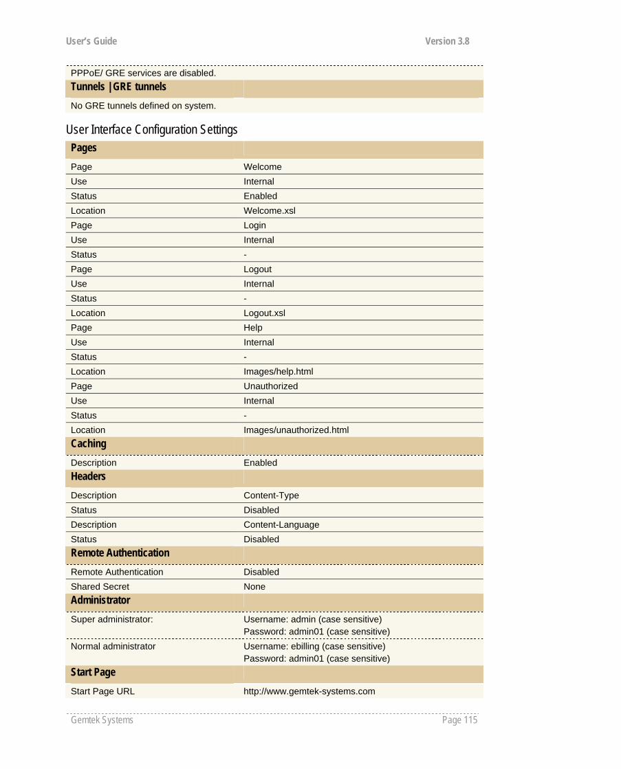
User’s Guide Version 3.8
Gemtek Systems Page 115
PPPoE/ GRE services are disabled. Tunnels | GRE tunnels No GRE tunnels defined on system.
User Interface Configuration Settings Pages
Page Welcome Use Internal Status Enabled Location Welcome.xsl Page Login Use Internal Status - Page Logout Use Internal Status - Location Logout.xsl Page Help Use Internal Status - Location Images/help.html Page Unauthorized Use Internal Status - Location Images/unauthorized.html Caching
Description Enabled Headers
Description Content-Type Status Disabled Description Content-Language Status Disabled Remote Authentication
Remote Authentication Disabled Shared Secret None Administrator
Super administrator: Username: admin (case sensitive) Password: admin01 (case sensitive)
Normal administrator Username: ebilling (case sensitive) Password: admin01 (case sensitive)
Start Page
Start Page URL http://www.gemtek-systems.com

User’s Guide Version 3.8
Gemtek Systems Page 116
Walled Garden
No free site (or walled garden) URL is specified. No free walled garden host is specified. Web Proxy
Web Proxy Enabled Port 3128, 8000, 8080
System Configuration Settings Configuration | Syslog Remote Log Status Disabled Host 0.0.0.0 Level Debug Configuration | Trace System History Size 102400 Level Information Configuration | Clock Date Time No further known parameter. Configuration | NTP NTP Service Enabled Host Time.windows.com
Time.nist.gov Configuration | Certificate By default Gemtek System certificate is uploaded in the system with following certificate information: Issuer Organization Name Gemtek Systems Subject Organization Name Gemtek Systems Validity Not Before Oct 7 7:46:53 2002 GMT Validity Not After Mar 12 7:46:53 2019 GMT Configuration | Save and Restore No further known parameters. Configuration | Pronto Gold Pronto Status Disabled HNS server URL 0.0.0.0:9989 Heartbeat interval Disabled Remote host 0.0.0.0 Remote port 7788 Configuration | Share Username Share User Name Disabled Access | Access Control Default Access Status Deny Network Address All SNMP Service Allow Network Address All

User’s Guide Version 3.8
Gemtek Systems Page 117
Access | Telnet Telnet Status Disabled Access | AAA
UAM Enabled EAP802.1x Disabled MAC Disabled Use Password RADIUS secret Password password (case sensitive) Access | UAT Interface Ixp0 UAT Status Enabled IP Address 192.168.3.224 Netmask 192.168.3.224 Access | Isolation Bindmac Disabled Isolation Disabled Access | NAV Interface Ixp0 IP Address 192.168.3.1 NAT Enabled Authentication Enabled Visitor Access Disabled Access | SNMP SNMP Service Enabled Name Name Location Location Contact Contact information Public Community Name Public Private Community Name Private Default Trap Community Name Private Authentication Failure Traps Generation Disabled Type RO User User Name public (case sensitive) Password password (case sensitive) Type RW User User Name private (case sensitive) Password password (case sensitive) There are no SNMP proxies on system. There are no SNMP traps on system. Access | Web Auth IP Disabled
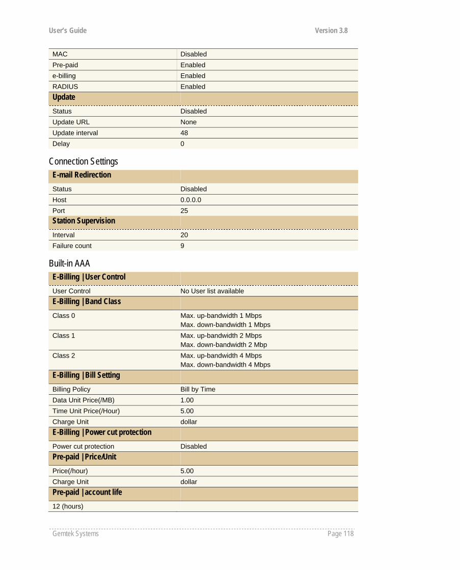
User’s Guide Version 3.8
Gemtek Systems Page 118
MAC Disabled Pre-paid Enabled e-billing Enabled RADIUS Enabled Update
Status Disabled Update URL None Update interval 48 Delay 0
Connection Settings E-mail Redirection
Status Disabled Host 0.0.0.0 Port 25 Station Supervision
Interval 20 Failure count 9
Built-in AAA E-Billing | User Control User Control No User list available E-Billing | Band Class Class 0 Max. up-bandwidth 1 Mbps
Max. down-bandwidth 1 Mbps Class 1 Max. up-bandwidth 2 Mbps
Max. down-bandwidth 2 Mbp Class 2 Max. up-bandwidth 4 Mbps
Max. down-bandwidth 4 Mbps E-Billing | Bill Setting Billing Policy Bill by Time Data Unit Price(/MB) 1.00 Time Unit Price(/Hour) 5.00 Charge Unit dollar E-Billing | Power cut protection Power cut protection Disabled Pre-paid | Price/Unit Price(/hour) 5.00 Charge Unit dollar Pre-paid | account life 12 (hours)
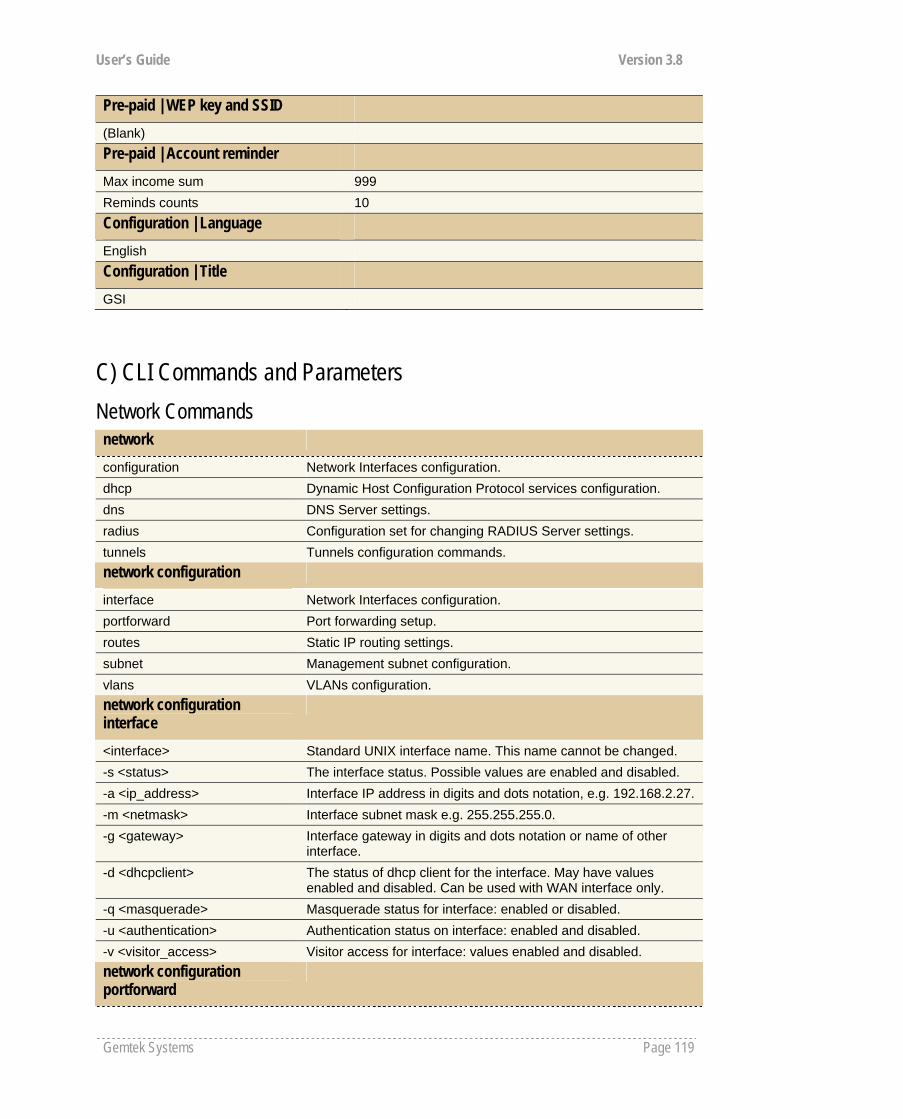
User’s Guide Version 3.8
Gemtek Systems Page 119
Pre-paid | WEP key and SSID (Blank) Pre-paid | Account reminder Max income sum 999 Reminds counts 10 Configuration | Language English Configuration | Title GSI
C) CLI Commands and Parameters Network Commands network
configuration Network Interfaces configuration. dhcp Dynamic Host Configuration Protocol services configuration. dns DNS Server settings. radius Configuration set for changing RADIUS Server settings. tunnels Tunnels configuration commands. network configuration
interface Network Interfaces configuration. portforward Port forwarding setup. routes Static IP routing settings. subnet Management subnet configuration. vlans VLANs configuration. network configuration interface
<interface> Standard UNIX interface name. This name cannot be changed. -s <status> The interface status. Possible values are enabled and disabled. -a <ip_address> Interface IP address in digits and dots notation, e.g. 192.168.2.27.-m <netmask> Interface subnet mask e.g. 255.255.255.0. -g <gateway> Interface gateway in digits and dots notation or name of other
interface. -d <dhcpclient> The status of dhcp client for the interface. May have values
enabled and disabled. Can be used with WAN interface only. -q <masquerade> Masquerade status for interface: enabled or disabled. -u <authentication> Authentication status on interface: enabled and disabled. -v <visitor_access> Visitor access for interface: values enabled and disabled. network configuration portforward
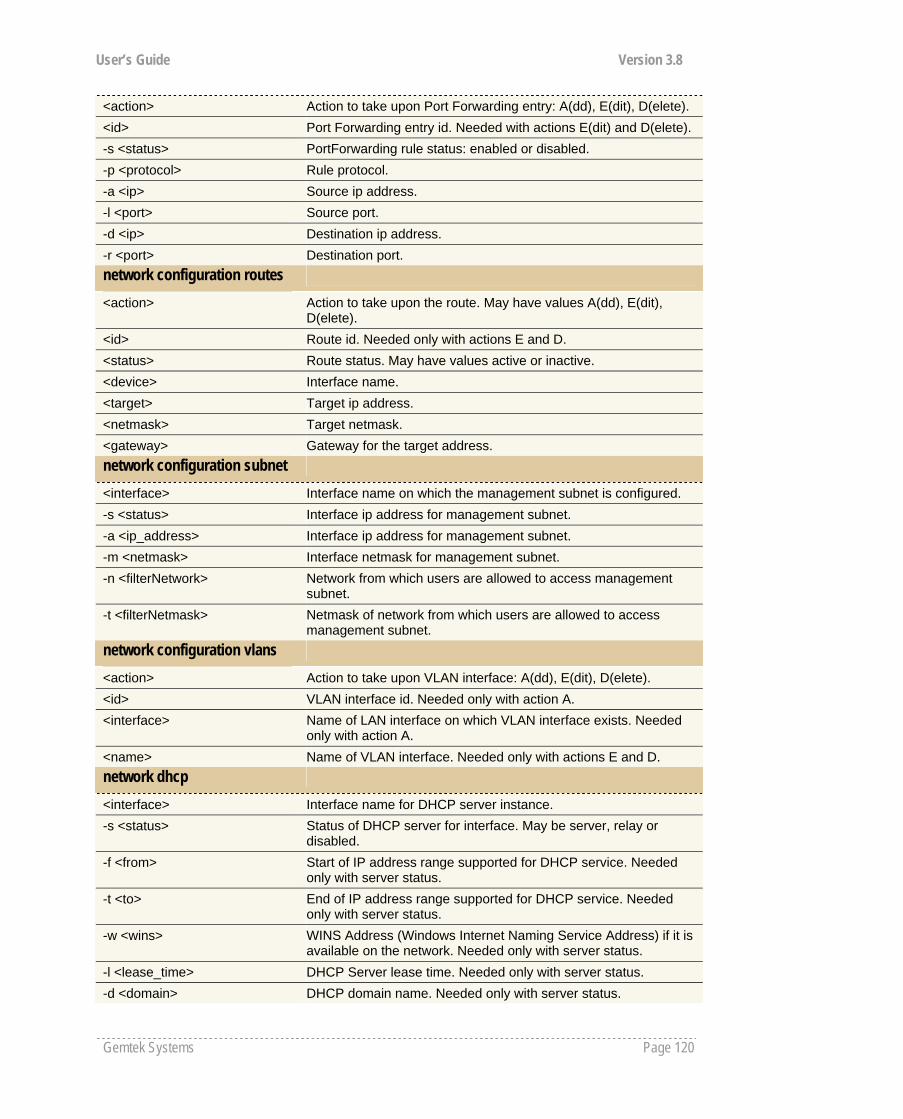
User’s Guide Version 3.8
Gemtek Systems Page 120
<action> Action to take upon Port Forwarding entry: A(dd), E(dit), D(elete). <id> Port Forwarding entry id. Needed with actions E(dit) and D(elete).-s <status> PortForwarding rule status: enabled or disabled. -p <protocol> Rule protocol. -a <ip> Source ip address. -l <port> Source port. -d <ip> Destination ip address. -r <port> Destination port. network configuration routes
<action> Action to take upon the route. May have values A(dd), E(dit), D(elete).
<id> Route id. Needed only with actions E and D. <status> Route status. May have values active or inactive. <device> Interface name. <target> Target ip address. <netmask> Target netmask. <gateway> Gateway for the target address. network configuration subnet
<interface> Interface name on which the management subnet is configured. -s <status> Interface ip address for management subnet. -a <ip_address> Interface ip address for management subnet. -m <netmask> Interface netmask for management subnet. -n <filterNetwork> Network from which users are allowed to access management
subnet. -t <filterNetmask> Netmask of network from which users are allowed to access
management subnet. network configuration vlans
<action> Action to take upon VLAN interface: A(dd), E(dit), D(elete). <id> VLAN interface id. Needed only with action A. <interface> Name of LAN interface on which VLAN interface exists. Needed
only with action A. <name> Name of VLAN interface. Needed only with actions E and D. network dhcp
<interface> Interface name for DHCP server instance. -s <status> Status of DHCP server for interface. May be server, relay or
disabled. -f <from> Start of IP address range supported for DHCP service. Needed
only with server status. -t <to> End of IP address range supported for DHCP service. Needed
only with server status. -w <wins> WINS Address (Windows Internet Naming Service Address) if it is
available on the network. Needed only with server status. -l <lease_time> DHCP Server lease time. Needed only with server status. -d <domain> DHCP domain name. Needed only with server status.

User’s Guide Version 3.8
Gemtek Systems Page 121
-c <circuit_id> Circuit ID - a unique NAS identifier. MAC address will be used by default. Needed only with relay status.
-n <dns_list> List of up to two DNS servers IP addresses. network dns
<type> DNS Server type. May be primary or secondary. <nameserver> DNS Server IP address in digits and dots notation, e.g.
192.168.2.27.
Network Radius Commands network radius
accounting_log For sending RADIUS accounting via syslog. proxy RADIUS Proxy configuration. servers Up to 32 different RADIUS servers' configuration. settings General RADIUS settings configuration. wisp WISP information and setup. network accounting_log
-l <status> Local accounting log status. Possible values are enabled or disabled.
-r <status> Remote accounting log status. Possible values are enabled or disabled.
-a <host> The host IP address where to send the accounting information. network radius servers
accounting Accounting RADIUS servers' configuration. authentication Authentication RADIUS servers' configuration. backup Accounting information backup servers configuration. network radius servers accounting
<id> RADIUS server id. -a <ip_address> RADIUS server IP address used for Radius accounting. -p <port> RADIUS server port used for Radius accounting. -s <secret> Shared secret key for accounting (must be the same on RADIUS
server and RADIUS client). network radius servers authentication
<action> Action to take uppon radius server. May have values A(dd), E(dit), D(elete).
<id> RADIUS server id. -n <name> RADIUS server name. -a <ip_address> RADIUS server IP address. -p <port> RADIUS server port. -s <secret> Shared secret key (must be the same on RADIUS server and
RADIUS client). -d <default> Sets the server as default. Possible values: yes. Note: there can
be only one default Radius server.

User’s Guide Version 3.8
Gemtek Systems Page 122
-r <status> Reverse accounting. May have values enabled or disabled. -w <status> Strip WISP name before sending to RADIUS. May have values
enabled or disabled. -u <method> UAM authentication method for RADIUS server. May have values
pap, chap, mschap1 and mschap2. network radius servers backup
<id> RADIUS server id. -b <status> If RADIUS Backup Server feature is on. May have values enabled
or disabled.
-a <ip_address> Backup RADIUS server IP address used for Radius accounting. -p <port> Backup RADIUS server port used for Radius accounting. -s <secret> Shared secret key for backup server(must be the same on
RADIUS server and RADIUS client). network radius settings -r <retries> Retry count of sending RADIUS packets before giving up. -t <timeout> Maximal amount of time before retrying RADIUS packets (in
seconds). -n <nas> NAS Server identification string. -o <user_timeout> Amount of time from user side (no network carrier) before closing
the connection (in seconds). -a <acct_update> Period after which server should update accounting information
(in seconds). -c <acct_retry> Retry time period in which server should try to update accounting
information before giving up (in seconds). -i <idle> Amount of user inactivity time, before automatically disconnecting
user from the network (in seconds). -u <bandwidth> Default Radius user upload bandwidth. -d <bandwidth> Default Radius user download bandwidth. network radius wisp
<action> A(dd), D(elete) <id> WISP Id. Usable only with D action. <name> WISP name. Usable only with A action. <radius_id> WISP Radius server id (from Radius authentication server list).
Usable only with A action. <interface> Interface name to which the WISP should be bound or none.
Usable only with A action.
Network Tunnels Commands network tunnels gre GRE client setup. ppp PPTP, PPPoE and GRE setup. pptp4vpn PPTP for VPN setup. network tunnels gre <action Action to take upon GRE tunnel: A(dd), E(dit), D(elete).
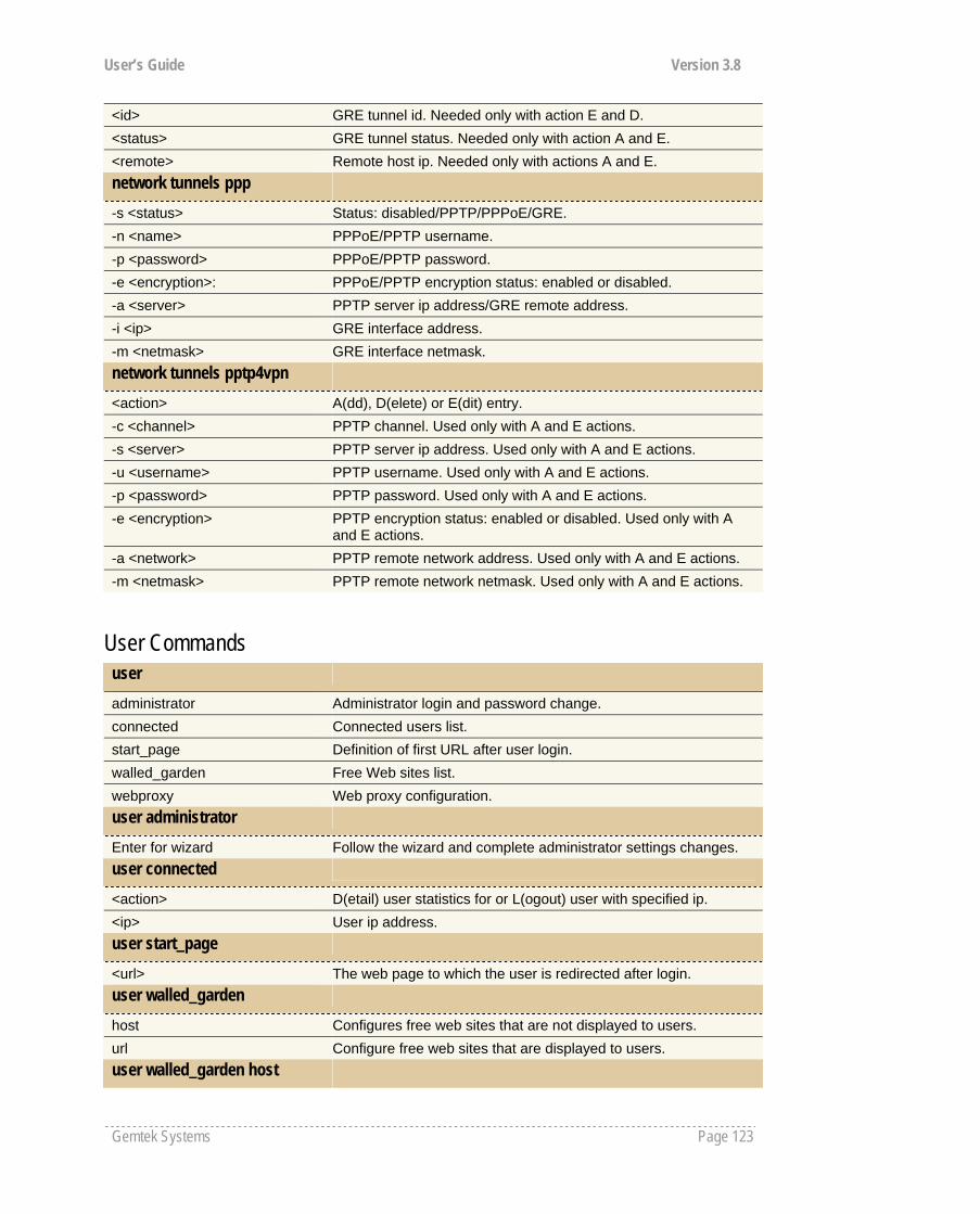
User’s Guide Version 3.8
Gemtek Systems Page 123
<id> GRE tunnel id. Needed only with action E and D. <status> GRE tunnel status. Needed only with action A and E. <remote> Remote host ip. Needed only with actions A and E. network tunnels ppp -s <status> Status: disabled/PPTP/PPPoE/GRE. -n <name> PPPoE/PPTP username. -p <password> PPPoE/PPTP password. -e <encryption>: PPPoE/PPTP encryption status: enabled or disabled. -a <server> PPTP server ip address/GRE remote address. -i <ip> GRE interface address. -m <netmask> GRE interface netmask. network tunnels pptp4vpn <action> A(dd), D(elete) or E(dit) entry. -c <channel> PPTP channel. Used only with A and E actions. -s <server> PPTP server ip address. Used only with A and E actions. -u <username> PPTP username. Used only with A and E actions. -p <password> PPTP password. Used only with A and E actions. -e <encryption> PPTP encryption status: enabled or disabled. Used only with A
and E actions. -a <network> PPTP remote network address. Used only with A and E actions. -m <netmask> PPTP remote network netmask. Used only with A and E actions.
User Commands user
administrator Administrator login and password change. connected Connected users list. start_page Definition of first URL after user login. walled_garden Free Web sites list. webproxy Web proxy configuration. user administrator
Enter for wizard Follow the wizard and complete administrator settings changes. user connected
<action> D(etail) user statistics for or L(ogout) user with specified ip. <ip> User ip address. user start_page
<url> The web page to which the user is redirected after login. user walled_garden
host Configures free web sites that are not displayed to users. url Configure free web sites that are displayed to users. user walled_garden host
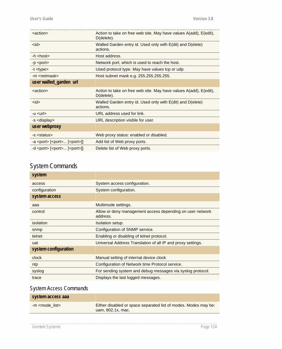
User’s Guide Version 3.8
Gemtek Systems Page 124
<action> Action to take on free web site. May have values A(add), E(edit), D(delete).
<id> Walled Garden entry id. Used only with E(dit) and D(elete) actions.
-h <host> Host address. -p <port> Network port, which is used to reach the host. -t <type> Used protocol type. May have values tcp or udp. -m <netmask> Host subnet mask e.g. 255.255.255.255. user walled_garden url
<action> Action to take on free web site. May have values A(add), E(edit), D(delete).
<id> Walled Garden entry id. Used only with E(dit) and D(elete) actions.
-u <url> URL address used for link. -s <display> URL description visible for user. user webproxy
-s <status> Web proxy status: enabled or disabled. -a <port> [<port>... [<port>]] Add list of Web proxy ports. -d <port> [<port>... [<port>]] Delete list of Web proxy ports.
System Commands system access System access configuration. configuration System configuration. system access aaa Multimode settings. control Allow or deny management access depending on user network
address. isolation Isolation setup. snmp Configuration of SNMP service. telnet Enabling or disabling of telnet protocol. uat Universal Address Translation of all IP and proxy settings. system configuration clock Manual setting of internal device clock ntp Configuration of Network time Protocol service. syslog For sending system and debug messages via syslog protocol. trace Displays the last logged messages.
System Access Commands system access aaa -m <mode_list> Either disabled or space separated list of modes. Modes may be:
uam, 802.1x, mac.

User’s Guide Version 3.8
Gemtek Systems Page 125
-u <use_password> Mac authentication mode password usage: 'radius' - use radius shared secret key, 'user' - use of user-defined password.
-p <password> User defined mac authentication password. system access control <action> Action to take upon management access entry: A(dd), E(dit),
D(elete) or default. <id> Management access entry id. Needed only when editing or
deleting entry. -s <service> Services for which the policy should be set: ssh, snmp, telnet or
all. -a <ip/bitmask> 'all' or network ip address and bitmask to (dis)allow service to. -p <policy> Management access policy: allow or deny(default is deny). system access isolation -b <status> Mac binding status: enabled or disabled. -i <status> Isolation status: enabled or disabled. system access snmp proxies SNMP proxies settings. settings SNMP service settings. traps SNMP traps settings. users SNMP users settings. system access snmp proxies <action> Action to take upon SNMP proxy entry: A(dd), E(dit) or D(elete). <id> Entry id. Needed only with Edit and Delete actions. -t <type> Proxy type. May have values v1, v2c. Can be used only when
adding or editing proxy. -a <ip_address> Proxy ip address. -c <community_name> Proxy community name. -l <oid_local> Proxy local OID. -r <oid_target> Proxy target OID. system access snmp settings -s <status> Status of SNMP service. -n <name> System name. -l <location> Location of the device. -c <contact> Contact information. -b <public_name> Public name of SNMP service. -r <private_name>: Private name of SNMP service. system access snmp traps <action> Action to take upon SNMP trap entry: A(dd), E(dit) or D(elete) <id> Entry id. Needed only with Edit and Delete actions. -c <community> SNMP community string. -a <ip_address> SNMP trap host address. -p <port> SNMP trap port. -t <type> SNMP trap type: v1, v2 or inform.
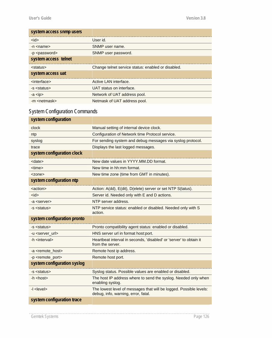
User’s Guide Version 3.8
Gemtek Systems Page 126
system access snmp users <id> User id. -n <name> SNMP user name. -p <password> SNMP user password. system access telnet <status> Change telnet service status: enabled or disabled. system access uat <interface> Active LAN interface. -s <status> UAT status on interface. -a <ip> Network of UAT address pool. -m <netmask> Netmask of UAT address pool.
System Configuration Commands system configuration clock Manual setting of internal device clock. ntp Configuration of Network time Protocol service. syslog For sending system and debug messages via syslog protocol. trace Displays the last logged messages. system configuration clock <date> New date values in YYYY.MM.DD format. <time> New time in hh:mm format. <zone> New time zone (time from GMT in minutes). system configuration ntp <action> Action: A(dd), E(dit), D(elete) server or set NTP S(tatus). <id> Server id. Needed only with E and D actions. -a <server> NTP server address. -s <status> NTP service status: enabled or disabled. Needed only with S
action. system configuration pronto -s <status> Pronto compatibility agent status: enabled or disabled. -u <server_url> HNS server url in format host:port. -h <interval> Heartbeat interval in seconds, 'disabled' or 'server' to obtain it
from the server. -a <remote_host> Remote host ip address. -p <remote_port> Remote host port. system configuration syslog -s <status> Syslog status. Possible values are enabled or disabled. -h <host> The host IP address where to send the syslog. Needed only when
enabling syslog. -l <level> The lowest level of messages that will be logged. Possible levels:
debug, info, warning, error, fatal. system configuration trace
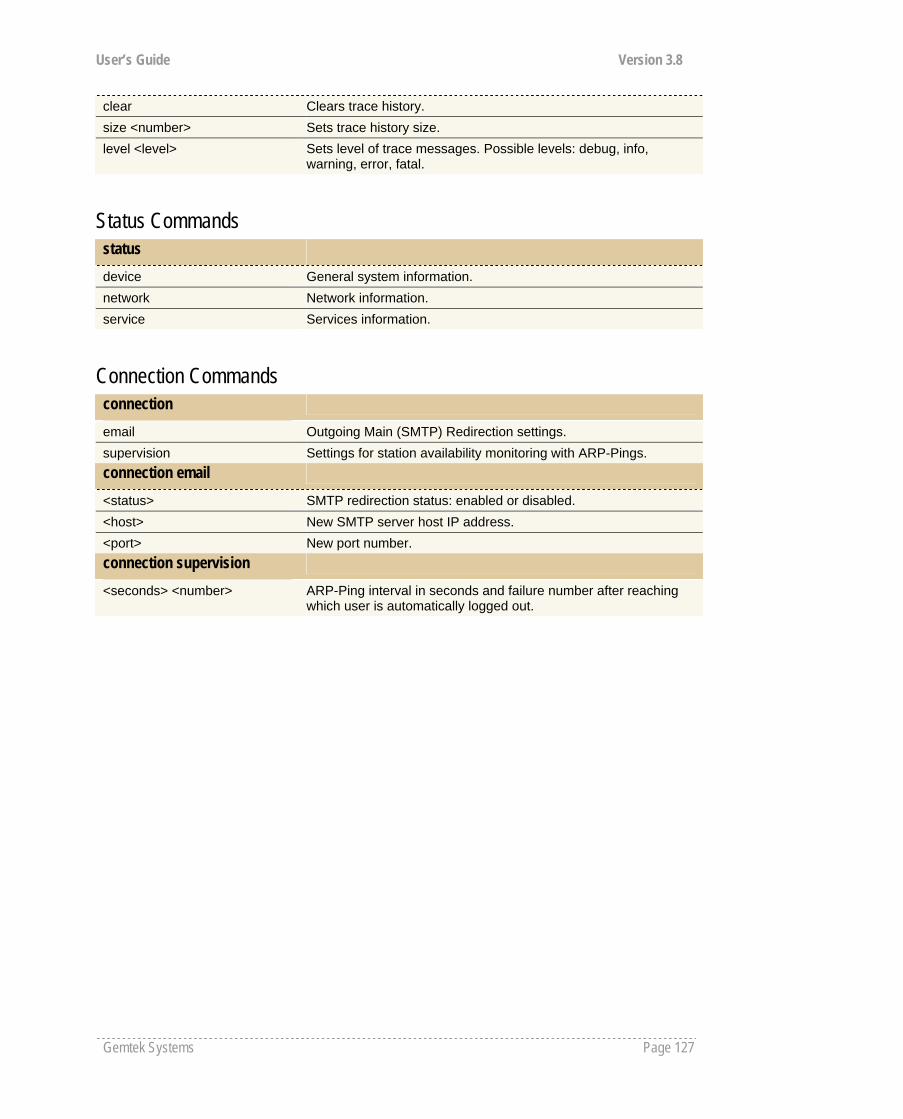
User’s Guide Version 3.8
Gemtek Systems Page 127
clear Clears trace history. size <number> Sets trace history size. level <level> Sets level of trace messages. Possible levels: debug, info,
warning, error, fatal.
Status Commands status device General system information. network Network information. service Services information.
Connection Commands connection
email Outgoing Main (SMTP) Redirection settings. supervision Settings for station availability monitoring with ARP-Pings. connection email
<status> SMTP redirection status: enabled or disabled. <host> New SMTP server host IP address. <port> New port number. connection supervision
<seconds> <number> ARP-Ping interval in seconds and failure number after reaching which user is automatically logged out.
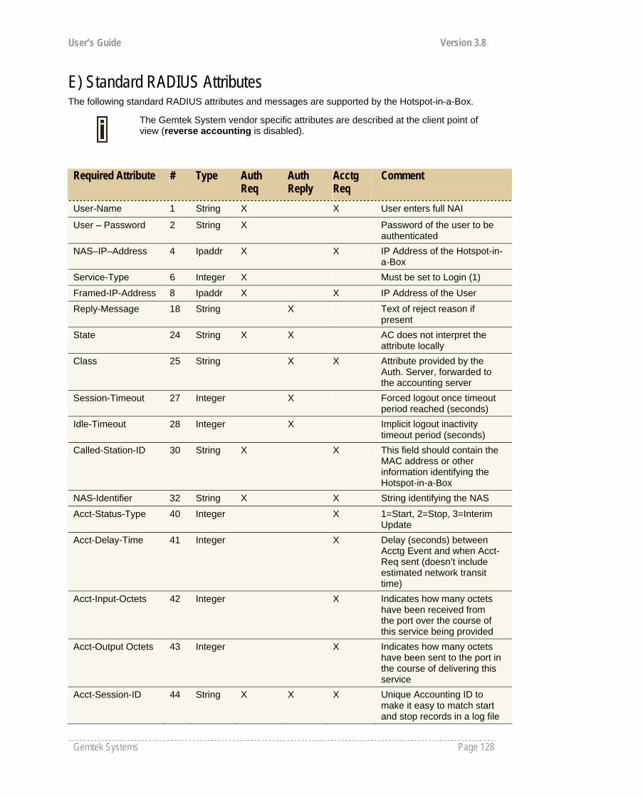
User’s Guide Version 3.8
Gemtek Systems Page 128
E) Standard RADIUS Attributes The following standard RADIUS attributes and messages are supported by the Hotspot-in-a-Box.
The Gemtek System vendor specific attributes are described at the client point of view (reverse accounting is disabled).
Required Attribute # Type Auth Req
Auth Reply
Acctg Req
Comment
User-Name 1 String X X User enters full NAI
User – Password 2 String X Password of the user to be authenticated
NAS–IP–Address 4 Ipaddr X X IP Address of the Hotspot-in-a-Box
Service-Type 6 Integer X Must be set to Login (1)
Framed-IP-Address 8 Ipaddr X X IP Address of the User
Reply-Message 18 String X Text of reject reason if present
State 24 String X X AC does not interpret the attribute locally
Class 25 String X X Attribute provided by the Auth. Server, forwarded to the accounting server
Session-Timeout 27 Integer X Forced logout once timeout period reached (seconds)
Idle-Timeout 28 Integer X Implicit logout inactivity timeout period (seconds)
Called-Station-ID 30 String X X This field should contain the MAC address or other information identifying the Hotspot-in-a-Box
NAS-Identifier 32 String X X String identifying the NAS
Acct-Status-Type 40 Integer X 1=Start, 2=Stop, 3=Interim Update
Acct-Delay-Time 41 Integer X Delay (seconds) between Acctg Event and when Acct-Req sent (doesn’t include estimated network transit time)
Acct-Input-Octets 42 Integer X Indicates how many octets have been received from the port over the course of this service being provided
Acct-Output Octets 43 Integer X Indicates how many octets have been sent to the port in the course of delivering this service
Acct-Session-ID 44 String X X X Unique Accounting ID to make it easy to match start and stop records in a log file

User’s Guide Version 3.8
Gemtek Systems Page 129
Acct-Session-Time 46 Integer X Call duration in seconds (already compensated for idle timeout)
Acct-Input-Packets 47 Integer X Indicates how many packets have been received from the port over the course of this service being provided
Acct-Output Packets
48 Integer X Indicates how many packets have been sent to the port in the course of delivering this service
Acct-Terminate-Cause
49 Integer X 1=Explicit Logoff, 4=Idle Timeout, 5=Session Timeout, 6=Admin Reset, 9=NAS Error, 10=NAS Request, 11=NAS Reboot
Acct-Input-Gigawords
52 Integer X This attribute indicates how many times the Acct-Input-Octets counter has wrapped around 232 over the course of this service being provided
Acct-Output-Gigawords
53 Integer X This attribute indicates how many times the Acct-Output-Octets counter has wrapped around 232 in the course of delivering this service
NAS-Port-Type 61 Integer X X 15=Ethernet, 19=802.11
Acct-Interim-Interval 85 Integer X Interval (seconds) to send accounting updates
Vendor Specific Attributes The Wi-Fi Alliance recommends a list of certain Vendor Specific Attributes (VSA). The VSA values are intended to provide location information to the backend processing system or to deliver service type information back to the Hotspot-in-a-Box.
The Wi-Fi Alliance has registered an IANA Private Enterprise Number (PEN) of 14122, which can be used to pass Vendor-Specific attributes to international roaming partners.
WISPr Vendor Specific Atributes
# Type Auth Req
Auth Reply
Acctg Req
Comment
Location-ID 1 String X X Hotspot Location Identifier
Location-Name 2 String X X Hotspot Location and Operator’s Name
Logoff-URL 3 String X URL for user to perform explicit logoff
Redirection-URL 4 String X URL of Start Page
Bandwidth-Min-Up 5 Integer X Minimum Transmit Rate (bps)Bandwidth-Min-Down
6 Integer X Minimum Receive Rate (bps)
Bandwidth-Max-Up 7 Integer X Maximum Transmit Rate (bps)
Bandwidth-Max-Down
8 Integer X Maximum Receive Rate (bps)
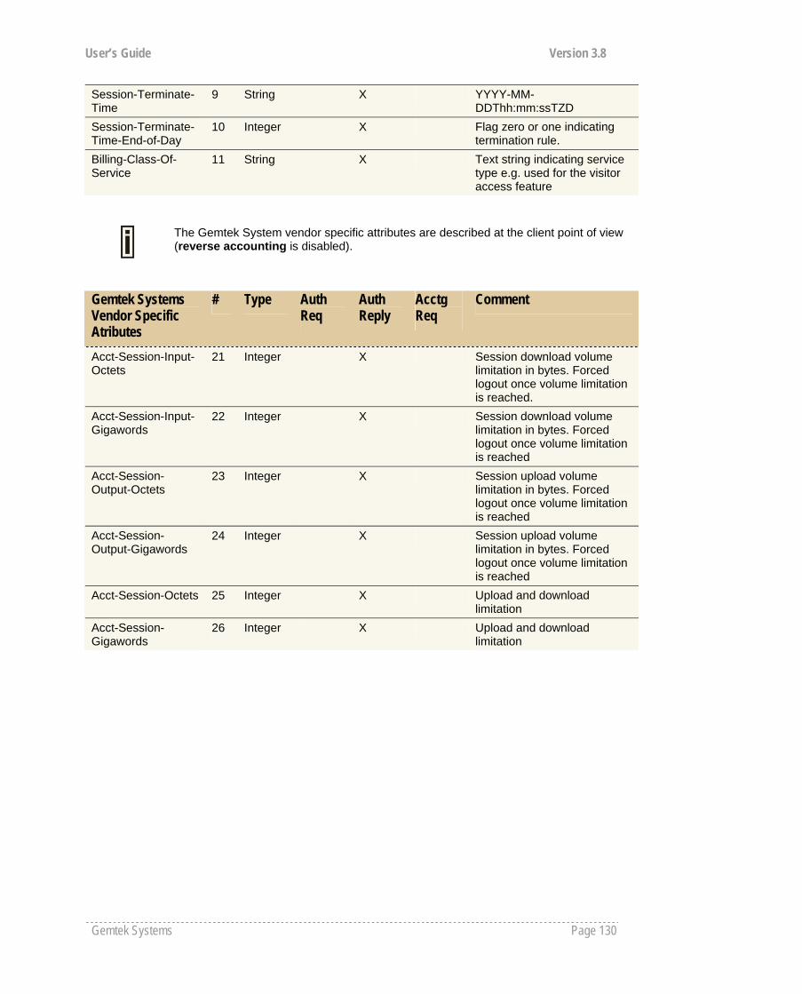
User’s Guide Version 3.8
Gemtek Systems Page 130
Session-Terminate-Time
9 String X YYYY-MM-DDThh:mm:ssTZD
Session-Terminate-Time-End-of-Day
10 Integer X Flag zero or one indicating termination rule.
Billing-Class-Of-Service
11 String X Text string indicating service type e.g. used for the visitor access feature
The Gemtek System vendor specific attributes are described at the client point of view (reverse accounting is disabled).
Gemtek Systems Vendor Specific Atributes
# Type Auth Req
Auth Reply
Acctg Req
Comment
Acct-Session-Input-Octets
21 Integer X Session download volume limitation in bytes. Forced logout once volume limitation is reached.
Acct-Session-Input-Gigawords
22 Integer X Session download volume limitation in bytes. Forced logout once volume limitation is reached
Acct-Session-Output-Octets
23 Integer X Session upload volume limitation in bytes. Forced logout once volume limitation is reached
Acct-Session-Output-Gigawords
24 Integer X Session upload volume limitation in bytes. Forced logout once volume limitation is reached
Acct-Session-Octets 25 Integer X Upload and download limitation
Acct-Session-Gigawords
26 Integer X Upload and download limitation
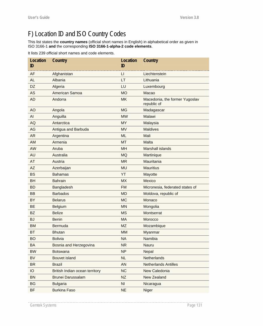
User’s Guide Version 3.8
Gemtek Systems Page 131
F) Location ID and ISO Country Codes This list states the country names (official short names in English) in alphabetical order as given in ISO 3166-1 and the corresponding ISO 3166-1-alpha-2 code elements.
It lists 239 official short names and code elements.
Location ID
Country Location ID
Country
AF Afghanistan LI Liechtenstein AL Albania LT Lithuania
DZ Algeria LU Luxembourg AS American Samoa MO Macao AD Andorra MK Macedonia, the former Yugoslav
republic of AO Angola MG Madagascar AI Anguilla MW Malawi AQ Antarctica MY Malaysia AG Antigua and Barbuda MV Maldives AR Argentina ML Mali AM Armenia MT Malta AW Aruba MH Marshall islands AU Australia MQ Martinique AT Austria MR Mauritania AZ Azerbaijan MU Mauritius BS Bahamas YT Mayotte BH Bahrain MX Mexico BD Bangladesh FM Micronesia, federated states of BB Barbados MD Moldova, republic of BY Belarus MC Monaco BE Belgium MN Mongolia BZ Belize MS Montserrat BJ Benin MA Morocco BM Bermuda MZ Mozambique BT Bhutan MM Myanmar BO Bolivia NA Namibia BA Bosnia and Herzegovina NR Nauru BW Botswana NP Nepal BV Bouvet island NL Netherlands BR Brazil AN Netherlands Antilles IO British Indian ocean territory NC New Caledonia BN Brunei Darussalam NZ New Zealand BG Bulgaria NI Nicaragua BF Burkina Faso NE Niger
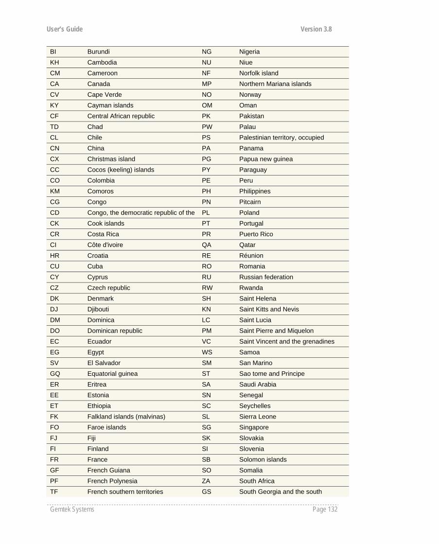
User’s Guide Version 3.8
Gemtek Systems Page 132
BI Burundi NG Nigeria KH Cambodia NU Niue CM Cameroon NF Norfolk island CA Canada MP Northern Mariana islands CV Cape Verde NO Norway KY Cayman islands OM Oman CF Central African republic PK Pakistan TD Chad PW Palau CL Chile PS Palestinian territory, occupied CN China PA Panama CX Christmas island PG Papua new guinea CC Cocos (keeling) islands PY Paraguay CO Colombia PE Peru KM Comoros PH Philippines CG Congo PN Pitcairn CD Congo, the democratic republic of the PL Poland CK Cook islands PT Portugal CR Costa Rica PR Puerto Rico CI Côte d'ivoire QA Qatar HR Croatia RE Réunion CU Cuba RO Romania CY Cyprus RU Russian federation CZ Czech republic RW Rwanda DK Denmark SH Saint Helena DJ Djibouti KN Saint Kitts and Nevis DM Dominica LC Saint Lucia DO Dominican republic PM Saint Pierre and Miquelon EC Ecuador VC Saint Vincent and the grenadines EG Egypt WS Samoa SV El Salvador SM San Marino GQ Equatorial guinea ST Sao tome and Principe ER Eritrea SA Saudi Arabia EE Estonia SN Senegal ET Ethiopia SC Seychelles FK Falkland islands (malvinas) SL Sierra Leone FO Faroe islands SG Singapore FJ Fiji SK Slovakia FI Finland SI Slovenia FR France SB Solomon islands GF French Guiana SO Somalia PF French Polynesia ZA South Africa TF French southern territories GS South Georgia and the south
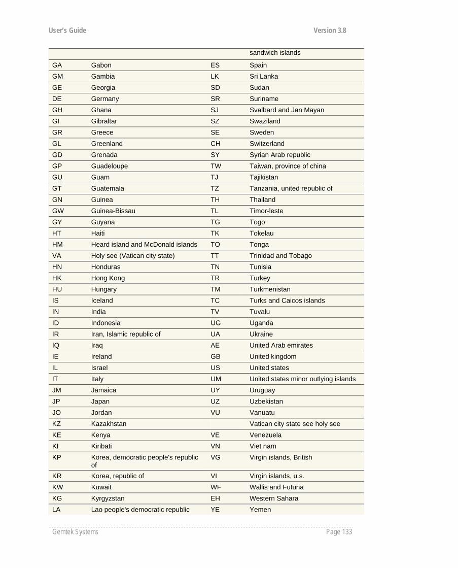
User’s Guide Version 3.8
Gemtek Systems Page 133
sandwich islands
GA Gabon ES Spain GM Gambia LK Sri Lanka GE Georgia SD Sudan DE Germany SR Suriname GH Ghana SJ Svalbard and Jan Mayan GI Gibraltar SZ Swaziland GR Greece SE Sweden GL Greenland CH Switzerland GD Grenada SY Syrian Arab republic GP Guadeloupe TW Taiwan, province of china GU Guam TJ Tajikistan GT Guatemala TZ Tanzania, united republic of GN Guinea TH Thailand GW Guinea-Bissau TL Timor-leste GY Guyana TG Togo HT Haiti TK Tokelau HM Heard island and McDonald islands TO Tonga VA Holy see (Vatican city state) TT Trinidad and Tobago HN Honduras TN Tunisia HK Hong Kong TR Turkey HU Hungary TM Turkmenistan IS Iceland TC Turks and Caicos islands IN India TV Tuvalu ID Indonesia UG Uganda IR Iran, Islamic republic of UA Ukraine IQ Iraq AE United Arab emirates IE Ireland GB United kingdom IL Israel US United states IT Italy UM United states minor outlying islands JM Jamaica UY Uruguay JP Japan UZ Uzbekistan JO Jordan VU Vanuatu KZ Kazakhstan Vatican city state see holy see KE Kenya VE Venezuela KI Kiribati VN Viet nam KP Korea, democratic people's republic
of VG Virgin islands, British
KR Korea, republic of VI Virgin islands, u.s. KW Kuwait WF Wallis and Futuna KG Kyrgyzstan EH Western Sahara LA Lao people's democratic republic YE Yemen

User’s Guide Version 3.8
Gemtek Systems Page 134
LV Latvia YU Yugoslavia LB Lebanon
Zaire see Congo, the democratic republic of the
LS Lesotho ZM Zambia LR Liberia ZW Zimbabwe LY Libyan Arab Jamahiriya
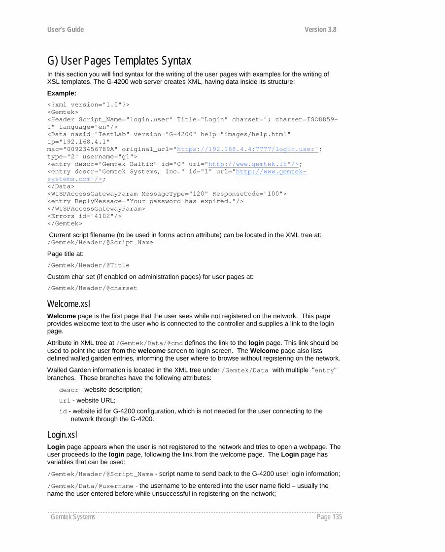
User’s Guide Version 3.8
Gemtek Systems Page 135
G) User Pages Templates Syntax In this section you will find syntax for the writing of the user pages with examples for the writing of XSL templates. The G-4200 web server creates XML, having data inside its structure:
Example: <?xml version="1.0"?> <Gemtek> <Header Script_Name="login.user" Title="Login" charset="; charset=ISO8859-1" language="en"/> <Data nasid="TestLab" version="G-4200" help="images/help.html" ip="192.168.4.1" mac="00923456789A" original_url="https://192.168.4.4:7777/login.user"; type="2" username="g1"> <entry descr="Gemtek Baltic" id="0" url="http://www.gemtek.lt"/>; <entry descr="Gemtek Systems, Inc." id="1" url="http://www.gemtek-systems.com"/>; </Data> <WISPAccessGatewayParam MessageType="120" ResponseCode="100"> <entry ReplyMessage="Your password has expired."/> </WISPAccessGatewayParam> <Errors id="4102"/> </Gemtek>
Current script filename (to be used in forms action attribute) can be located in the XML tree at: /Gemtek/Header/@Script_Name
Page title at:
/Gemtek/Header/@Title
Custom char set (if enabled on administration pages) for user pages at:
/Gemtek/Header/@charset
Welcome.xsl Welcome page is the first page that the user sees while not registered on the network. This page provides welcome text to the user who is connected to the controller and supplies a link to the login page.
Attribute in XML tree at /Gemtek/Data/@cmd defines the link to the login page. This link should be used to point the user from the welcome screen to login screen. The Welcome page also lists defined walled garden entries, informing the user where to browse without registering on the network.
Walled Garden information is located in the XML tree under /Gemtek/Data with multiple "entry" branches. These branches have the following attributes:
descr - website description; url - website URL; id - website id for G-4200 configuration, which is not needed for the user connecting to the
network through the G-4200.
Login.xsl Login page appears when the user is not registered to the network and tries to open a webpage. The user proceeds to the login page, following the link from the welcome page. The Login page has variables that can be used:
/Gemtek/Header/@Script_Name - script name to send back to the G-4200 user login information;
/Gemtek/Data/@username - the username to be entered into the user name field – usually the name the user entered before while unsuccessful in registering on the network;

User’s Guide Version 3.8
Gemtek Systems Page 136
/Gemtek/Data/@ip - detected user IP from which he/she tries to register on the network;
/Gemtek/Data/@mac - detected users MAC address;
/Gemtek/Errors/@id - returned error code, which can be as follows:
error description 4101 Failed to authorize. 4102 Login or/and password incorrect. 4103 Network connection failed. 4104 Accounting error. 4105 Unknown authorization error. 4106 Could not get redirection URL. 4107 Already logged in.
/Gemtek/Data/@type - returns to G-4200 response for login request. Type values are as follows:
error description 0 Ok - logged in, redirect user to start page 1 Failed to authorize 2 Login or/and password incorrect 3 Network connection failed 4 Accounting error 5 User already logged in
It is advisable to first check the error codes, because they return more precise information. Branch "Type" returns RADIUS server response, which gives additional information about the user status. This can help in detecting whether the user is just logged in or has come to this page while already logged-in.
/Gemtek/WISPAccessGatewayParam/entry/@ReplyMessage - the RADIUS server response message on user logon [optional]. This parameter supports multiple messages.
This optional RADIUS Reply-Message's could provide more detailed information, why user logon failed.
/Gemtek/Data/@cmd - link to logout page. The logout page displays network usage statistics and provides the logout from the network function.
/Gemtek/Data/@url - the URL of start page to where the user is redirected after successful login. Usually it can be the website of the company or organization providing the G-4200 controller and configuring the users to visit their website.
/Gemtek/Data/@help - link to help page regarding how the user should register on the network.
When the user clicks the login button, information is sent to: /Gemtek/Header/@Script_Name location with following information:
username - user name to register to network; password - user password.
When the form is submitted, user information is checked and indication of success or failure is returned.
Logout.xsl The logout page displays network usage statistics and the user ability to logout from the network. The Logout page is displayed after the successful login and with usage statistics which are automatically refreshed after a defined time period.
Logout page has variables:
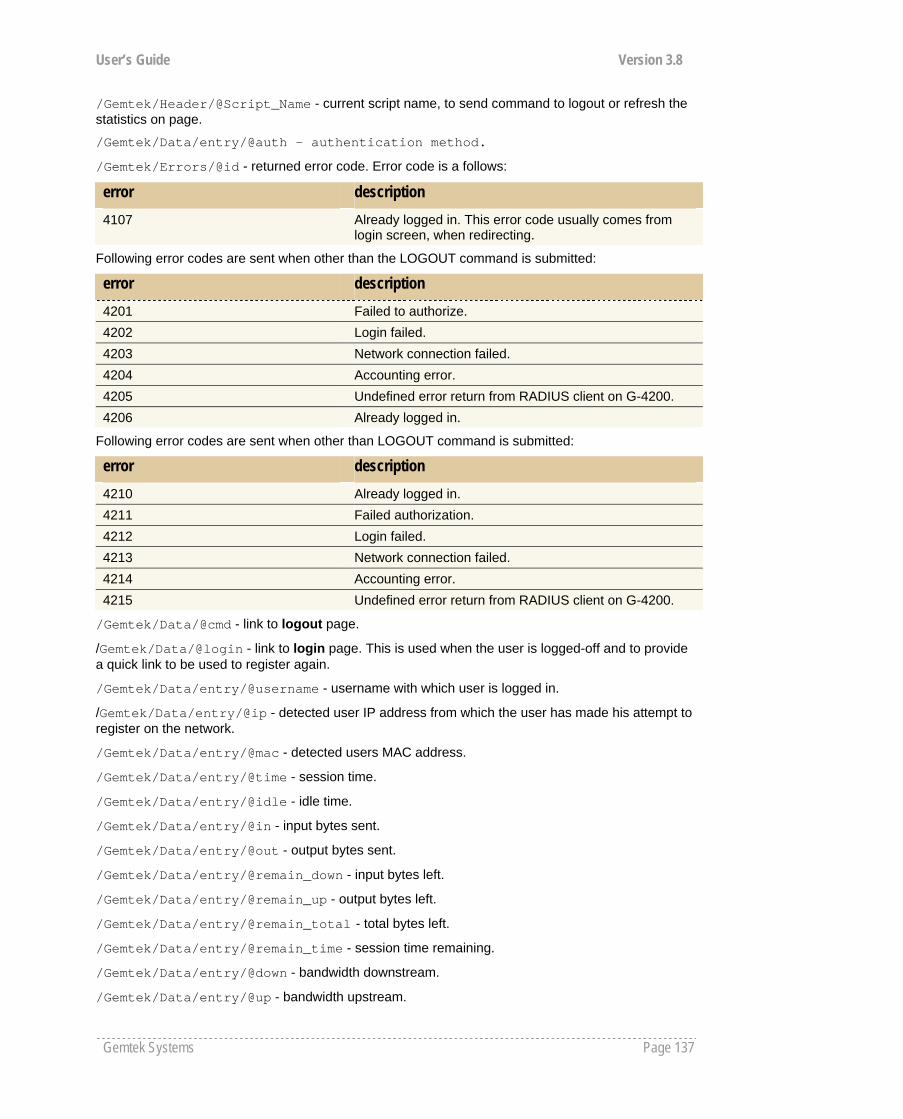
User’s Guide Version 3.8
Gemtek Systems Page 137
/Gemtek/Header/@Script_Name - current script name, to send command to logout or refresh the statistics on page.
/Gemtek/Data/entry/@auth - authentication method.
/Gemtek/Errors/@id - returned error code. Error code is a follows:
error description 4107 Already logged in. This error code usually comes from
login screen, when redirecting.
Following error codes are sent when other than the LOGOUT command is submitted:
error description 4201 Failed to authorize. 4202 Login failed. 4203 Network connection failed. 4204 Accounting error. 4205 Undefined error return from RADIUS client on G-4200. 4206 Already logged in.
Following error codes are sent when other than LOGOUT command is submitted:
error description 4210 Already logged in. 4211 Failed authorization. 4212 Login failed. 4213 Network connection failed. 4214 Accounting error. 4215 Undefined error return from RADIUS client on G-4200.
/Gemtek/Data/@cmd - link to logout page.
/Gemtek/Data/@login - link to login page. This is used when the user is logged-off and to provide a quick link to be used to register again.
/Gemtek/Data/entry/@username - username with which user is logged in.
/Gemtek/Data/entry/@ip - detected user IP address from which the user has made his attempt to register on the network.
/Gemtek/Data/entry/@mac - detected users MAC address.
/Gemtek/Data/entry/@time - session time.
/Gemtek/Data/entry/@idle - idle time.
/Gemtek/Data/entry/@in - input bytes sent.
/Gemtek/Data/entry/@out - output bytes sent.
/Gemtek/Data/entry/@remain_down - input bytes left.
/Gemtek/Data/entry/@remain_up - output bytes left.
/Gemtek/Data/entry/@remain_total - total bytes left.
/Gemtek/Data/entry/@remain_time - session time remaining.
/Gemtek/Data/entry/@down - bandwidth downstream.
/Gemtek/Data/entry/@up - bandwidth upstream.

User’s Guide Version 3.8
Gemtek Systems Page 138
If there is no /Gemtek/Data/entry in XML tree, it indicates that the user is not logged in.
Logout page has two purposes:
Log off the user Show the user usage statistics.
To log off the user, call the script defined in /Gemtek/Header/@Script_Name with variable cmd set to logout. This could be done trough POST or simply GET methods supplying simple link with parameters:
<a href="/logout.user?cmd=logout">.
To get user usage statistics, simply refresh the script defined in /Gemtek/Header/@Script_Name with no variables set. This could be done by defining the simple link:
<a href="/logout.user">.
Help.html This is a HTML file with no embedded cgi prepared. It is advisable to write instructions for the user on how to register to the network or what to do in the case of troubleshooting.
Unauthorized.html This page appears if the user is not registered on the network or the web authentication is not provided on the AC. It is recommended to include information on how to contact the network administrator (e.g. phone number).
Smart Client The G-4200 cannot only be used with a browser, but with a smart client connected to the G-4200 through HTTPS connection; thus, retrieving information given as XML in the same login.user output. To support a smart client, the following lines should be included in all user XSL templates:
<xsl:import href="xml-in-comments.xsl"/>
<xsl:apply-templates select="Gemtek/WISPAccessGatewayParam"/>
Commands for User Pages A user who is not logged in and trying to browse the Internet will be redirected to the welcome page automatically.
The welcome page address is:
https://G-4200_ip_address/welcome.user
The login page address is:
https://G-4200_ip_address/login.user
The logout and session information page address is:
https://G-4200_ip_address/logout.user
For the user who is logged in, the form should be posted to /login.user address and the form should have the following parameters:
username - username to log on; password - user password; 'cmd' with value 'login'.
To receive connected user session information, the following address should be used:
https://G-4200_ip_address/logout.user
To disconnect a user who is currently connected, the following address should be used:
https://G-4200_ip_address/logout.user with parameter 'cmd' with value 'logout'.
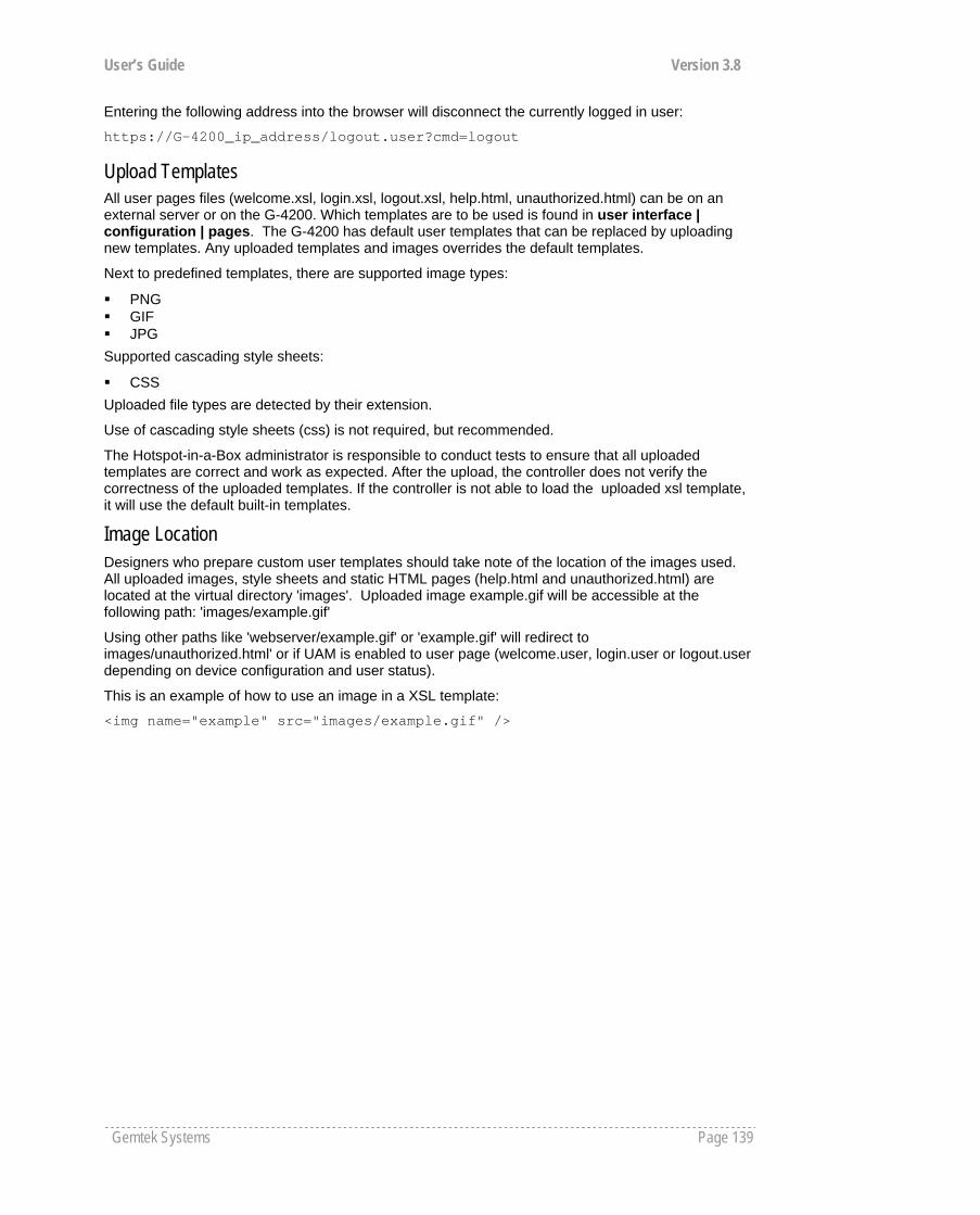
User’s Guide Version 3.8
Gemtek Systems Page 139
Entering the following address into the browser will disconnect the currently logged in user:
https://G-4200_ip_address/logout.user?cmd=logout
Upload Templates All user pages files (welcome.xsl, login.xsl, logout.xsl, help.html, unauthorized.html) can be on an external server or on the G-4200. Which templates are to be used is found in user interface | configuration | pages. The G-4200 has default user templates that can be replaced by uploading new templates. Any uploaded templates and images overrides the default templates.
Next to predefined templates, there are supported image types:
PNG GIF JPG
Supported cascading style sheets:
CSS Uploaded file types are detected by their extension.
Use of cascading style sheets (css) is not required, but recommended.
The Hotspot-in-a-Box administrator is responsible to conduct tests to ensure that all uploaded templates are correct and work as expected. After the upload, the controller does not verify the correctness of the uploaded templates. If the controller is not able to load the uploaded xsl template, it will use the default built-in templates.
Image Location Designers who prepare custom user templates should take note of the location of the images used. All uploaded images, style sheets and static HTML pages (help.html and unauthorized.html) are located at the virtual directory 'images'. Uploaded image example.gif will be accessible at the following path: 'images/example.gif'
Using other paths like 'webserver/example.gif' or 'example.gif' will redirect to images/unauthorized.html' or if UAM is enabled to user page (welcome.user, login.user or logout.user depending on device configuration and user status).
This is an example of how to use an image in a XSL template:
<img name="example" src="images/example.gif" />
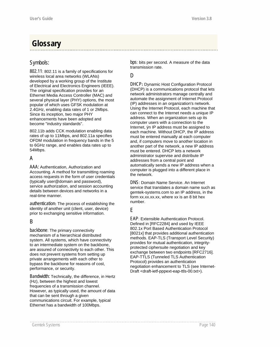
User’s Guide Version 3.8
Gemtek Systems Page 140
Symbols: 802.11: 802.11 is a family of specifications for wireless local area networks (WLANs) developed by a working group of the Institute of Electrical and Electronics Engineers (IEEE). The original specification provides for an Ethernet Media Access Controller (MAC) and several physical layer (PHY) options, the most popular of which uses GFSK modulation at 2.4GHz, enabling data rates of 1 or 2Mbps. Since its inception, two major PHY enhancements have been adopted and become "industry standards".
802.11b adds CCK modulation enabling data rates of up to 11Mbps, and 802.11a specifies OFDM modulation in frequency bands in the 5 to 6GHz range, and enables data rates up to 54Mbps.
A AAA: Authentication, Authorization and Accounting. A method for transmitting roaming access requests in the form of user credentials (typically user@domain and password), service authorization, and session accounting details between devices and networks in a real-time manner.
authentication: The process of establishing the identity of another unit (client, user, device) prior to exchanging sensitive information.
B backbone: The primary connectivity mechanism of a hierarchical distributed system. All systems, which have connectivity to an intermediate system on the backbone, are assured of connectivity to each other. This does not prevent systems from setting up private arrangements with each other to bypass the backbone for reasons of cost, performance, or security.
Bandwidth: Technically, the difference, in Hertz (Hz), between the highest and lowest frequencies of a transmission channel. However, as typically used, the amount of data that can be sent through a given communications circuit. For example, typical Ethernet has a bandwidth of 100Mbps.
bps: bits per second. A measure of the data transmission rate.
D DHCP: Dynamic Host Configuration Protocol (DHCP) is a communications protocol that lets network administrators manage centrally and automate the assignment of Internet Protocol (IP) addresses in an organization's network. Using the Internet Protocol, each machine that can connect to the Internet needs a unique IP address. When an organization sets up its computer users with a connection to the Internet, ÿn IP address must be assigned to each machine. Without DHCP, the IP address must be entered manually at each computer and, if computers move to another location in another part of the network, a new IP address must be entered. DHCP lets a network administrator supervise and distribute IP addresses from a central point and automatically sends a new IP address when a computer is plugged into a different place in the network.
DNS: Domain Name Service. An Internet service that translates a domain name such as gemtek-systems.com to an IP address, in the form xx.xx.xx.xx, where xx is an 8 bit hex number.
E EAP: Extensible Authentication Protocol. Defined in [RFC2284] and used by IEEE 802.1x Port Based Authentication Protocol [8021x] that provides additional authentication methods. EAP-TLS (Transport Level Security) provides for mutual authentication, integrity-protected ciphersuite negotiation and key exchange between two endpoints [RFC2716]. EAP-TTLS (Tunneled TLS Authentication Protocol) provides an authentication negotiation enhancement to TLS (see Internet-Draft <draft-ietf-pppext-eap-ttls-00.txt>).
Glossary

User’s Guide Version 3.8
Gemtek Systems Page 141
G gateway: A gateway is a network point that acts as an entrance to another network. On the Internet, a node or stopping point can be either a gateway node or a host (end-point) node. Both the computers of Internet users and the computers that serve pages to users are host nodes. The computers that control traffic within your company's network or at your local Internet service provider (ISP) are gateway nodes.
H hotspot: A hotspot is wireless public access system that allows subscribers to be connected to a wireless network in order to access the Internet or other devices, such as printers. Hot-spots are created by WLAN access points, installed in public venues. Common locations for public access are hotels, airport lounges, railway stations or coffee shops.
hotspot operator: An entity that operates a facility consisting of a Wi-Fi public access network and participates in the authentication.
HTTP: The Hypertext Transfer Protocol (HTTP) is the set of rules for exchanging files (text, graphic images, sound, video, and other multimedia files) on the World Wide Web. Relative to the TCP/IP suite of protocols (which are the basis for information exchange on the Internet), HTTP is an application protocol.
HTTPS: HTTPS (Hypertext Transfer Protocol over Secure Socket Layer, or HTTP over SSL) is a Web protocol developed by Netscape and built into its browser that encrypts and decrypts user page requests as well as the pages that are returned by the Web server. HTTPS is really just the use of Netscape's Secure Socket Layer (SSL) as a sublayer under its regular HTTP application layering.
I ICMP: ICMP (Internet Control Message Protocol) is a message control and error-reporting protocol between a host server and a gateway to the Internet. ICMP uses Internet Protocol (IP) datagrams, but the messages are processed by the IP software and are not directly apparent to the application user.
IEEE: Institute of Electrical and Electronics Engineers. The IEEE describes itself as the world's largest professional society. The IEEE fosters the development of standards that often become national and international standards, such as 802.11.
IP: The Internet Protocol (IP) is the method or protocol by which data is sent from one computer to another on the Internet. Each computer (known as a host) on the Internet has at least one IP address that uniquely identifies it from all other computers on the Internet. When you send or receive data (for example, an e-mail note or a Web page), the message gets divided into little chunks called packets. Each of these packets contains both the sender's Internet address and the receiver's address. Any packet is sent first to a gateway computer that understands a small part of the Internet. The gateway computer reads the destination address and forwards the packet to an adjacent gateway that in turn reads the destination address and so forth across the Internet until one gateway recognizes the packet as belonging to a computer within its immediate neighborhood or domain. That gateway then forwards the packet directly to the computer whose address is specified.
IPsec: IPsec (Internet Protocol Security) is a developing standard for security at the network or packet processing layer of network communication. Earlier security approaches have inserted security at the application layer of the communications model. IPsec will be especially useful for implementing virtual private networks and for remote user access through dial-up connection to private networks. A big advantage of IPsec is that security arrangements can be handled without requiring changes to individual user computers. Cisco has been a leader in proposing IPsec as a standard (or combination of standards and technologies) and has included support for it in its network routers.
IPsec provides two choices of security service: Authentication Header (AH), which essentially allows authentication of the sender of data, and Encapsulating Security Payload (ESP), which supports both authentication of the sender and encryption of data as well. The specific information associated with each of these services is inserted into the packet in a header that follows the IP packet header. Separate key protocols can be selected, such as the ISAKMP/Oakley protocol.

User’s Guide Version 3.8
Gemtek Systems Page 142
ISP: An ISP (Internet Service Provider) is a company that provides individuals and other companies access to the Internet and other related services such as Web site building and virtual hosting. An ISP has the equipment and the telecommunication line access required to have a point-of-presence on the Internet for the geographic area served.
L LAN: A local area network (LAN) is a group of computers and associated devices that share a common communications line and typically share the resources of a single processor or server within a small geographic area (for example, within an office building). Usually, the server has applications and data storage that are shared in common by multiple computer users. A local area network may serve as few as two or three users (for example, in a home network) or many as thousands of users (for example, in an FDDI network).
M MAC: Medium Access Control. In a WLAN network card, the MAC is the radio controller protocol. It corresponds to the ISO Network Model's level 2 Data Link layer. The IEEE 802.11 standard specifies the MAC protocol for medium sharing, packet formatting and addressing, and error detection.
N NAT: NAT (Network Address Translation) is the translation of an Internet Protocol address (IP address) used within one network to a different IP address known within another network. One network is designated the inside network and the other is the outside. Typically, a company maps its local inside network addresses to one or more global outside IP addresses and unmaps the global IP addresses on incoming packets back into local IP addresses.
NAT is included as part of a router and is often part of a corporate firewall.
P POP3: POP3 (Post Office Protocol 3) is the most recent version of a standard protocol for receiving e-mail. POP3 is a client/server protocol in which e-mail is received and held for you by your Internet server. Periodically, you (or your client e-mail receiver) check your mail-box on the server and download any mail. POP3 is built into the Netmanage suite of Internet products and one of the most popular e-mail products, Eudora. It's also built into the Netscape and Microsoft Internet Explorer browsers.
PPP: PPP (Point-to-Point Protocol) is a protocol for communication between two computers using a serial interface, typically a personal computer connected by phone line to a server. PPP uses the Internet protocol (IP) (and is designed to handle others). It is sometimes considered a member of the TCP/IP suite of protocols. Relative to the Open Systems Interconnection (OSI) reference model, PPP provides layer 2 (data-link layer) service. Essentially, it packages your computer's TCP/IP packets and forwards them to the server where they can actually be put on the Internet.
PPP is a full-duplex protocol that can be used on various physical media, including twisted pair or fiber optic lines or satellite transmission. It uses a variation of High Speed Data Link Control (HDLC) for packet encapsulation.
PPP is usually preferred over the earlier de facto standard Serial Line Internet Protocol (SLIP) because it can handle synchronous as well as asynchronous communication. PPP can share a line with other users and it has error detection that SLIP lacks. Where a choice is possible, PPP is preferred.
PPPoE: PPPoE (Point-to-Point Protocol over Ethernet) is a specification for connecting multiple computer users on an Ethernet local area network to a remote site through common customer premises equipment, which is the telephone company's term for a modem and similar devices. PPPoE can be used to have an office or building-full of users share a common Digital Subscriber Line (DSL), cable modem, or wireless connection to the Internet. PPPoE combines the Point-to-Point Protocol (PPP), commonly used in dialup connections, with the Ethernet protocol, which supports multiple users in a local area network. The PPP protocol information is encapsulated within an Ethernet frame.
User’s Guide Version 3.8
Gemtek Systems Page 143
PPPoE has the advantage that neither the telephone company nor the Internet service provider (ISP) needs to provide any special support. Unlike dialup connections, DSL and cable modem connections are "always on." Since a number of different users are sharing the same physical connection to the remote service provider, a way is needed to keep track of which user traffic should go to and which user should be billed. PPPoE provides for each user-remote site session to learn each other's network addresses (during an initial exchange called "discovery"). Once a session is established between an individual user and the remote site (for example, an Internet service provider), the session can be monitored for billing purposes.
PPTP: Point-to-Point Tunneling Protocol (PPTP) is a protocol (set of communication rules) that allows corporations to extend their own corporate network through private "tunnels" over the public Internet. Effectively, a corporation uses a wide-area network as a single large local area network. This kind of interconnection is known as a virtual private network (VPN).
R RADIUS: RADIUS (Remote Authentication Dial-In User Service) is a client/server protocol and software that enables remote access servers to communicate with a central server to authenticate dial-in users and authorize their access to the requested system or service. RADIUS allows a company to maintain user profiles in a central database that all remote servers can share. It provides better security, allowing a company to set up a policy that can be applied at a single administered network point. Having a central service also means that it's easier to track usage for billing and for keeping network statistics.
S SNMP: Simple Network Management Protocol (SNMP) is the protocol governing network management and the monitoring of network devices and their functions. It is not necessarily limited to TCP/IP networks.
SNMP is described formally in the Internet Engineering Task Force (IETF) Request for Comment (RFC) 1157 and in a number of other related RFCs.
SSL: The Secure Sockets Layer (SSL) is a commonly-used protocol for managing the security of a message transmission on the Internet. SSL has recently been succeeded by Transport Layer Security (TLS), which is based on SSL. SSL uses a program layer located between the Internet's Hypertext Transfer Protocol (HTTP) and Transport Control Protocol (TCP) layers. The "sockets" part of the term refers to the sockets method of passing data back and forth between a client and a server program in a network or between program layers in the same computer. SSL uses the public-and-private key encryption system from RSA, which also includes the use of a digital certificate.
T TCP: TCP (Transmission Control Protocol) is a set of rules (protocol) used along with the Internet Protocol (IP) to send data in the form of message units between computers over the Internet. While IP takes care of handling the actual delivery of the data, TCP takes care of keeping track of the individual units of data (called packets) that a message is divided into for efficient routing through the Internet.
TCP is a connection-oriented protocol, which means that a connection is established and maintained until such time as the message or messages to be exchanged by the application programs at each end have been exchanged. TCP is responsible for ensuring that a message is divided into the packets that IP manages and for reassembling the packets back into the complete message at the other end. In the Open Systems Interconnection (OSI) communication model, TCP is in layer 4, the Transport Layer.
TCP/IP: TCP/IP (Transmission Control Protocol/Internet Protocol) is the basic communication language or protocol of the Internet. It can also be used as a communications protocol in a private network (either an intranet or an extranet). When you are set up with direct access to the Internet, your computer is provided with a copy of the TCP/IP program just as every other computer that you may send messages to or get information from also has a copy of TCP/IP.
User’s Guide Version 3.8
Gemtek Systems Page 144
TCP/IP is a two-layer program. The higher layer, Transmission Control Protocol, manages the assembling of a message or file into smaller packets that are transmitted over the Internet and received by a TCP layer that reassembles the packets into the original message. The lower layer, Internet Protocol, handles the address part of each packet so that it gets to the right destination.
Telnet: Telnet is the way to access someone else's computer, assuming they have given permission. (Such a computer is frequently called a host computer.) More technically, Telnet is a user command and an underlying TCP/IP protocol for accessing remote computers. On the Web, HTTP and FTP protocols allow to request specific files from remote computers, but not to actually be logged on as a user of that computer.
U UAM: Universal Access Method is the current recommended methodology for providing secure web-based service presentment, authentication, authorization and accounting of users is a WISP network. This methodology enables any standard Wi-Fi enabled TCP/IP device with a browser to gain access to the WISP network.
W WAN: A wide area network (WAN) is a geographically dispersed telecommunications network. The term distinguishes a broader telecommunication structure from a local area network (LAN). A wide area network may be privately owned or rented, but the term usually connotes the inclusion of public (shared user) networks. An intermediate form of network in terms of geography is a metropolitan area network (MAN).
X XSL (Extensible Style sheet Language), formerly called Extensible Style Language, is a language for creating a style sheet that describes how data sent over the Web using the Extensible Markup Language (XML) is to be presented to the user.
A AAA, 7
configuration, 87 AC specification, 111 access AC
using KickStart utility, 13 using Web-browser, 12
access control on device, 85 administrator, 75 authentication, 89
B back pannel, 9
C certificates upload, 82 CLI, 39
connection commands, 127 network commands, 119
network RADIUS commands, 121 network tunnels commands, 122 status commands, 127 system commands, 124 system configuration commands, 126 user commands, 123
CLI commands connection, 39 exit, 44 login, 39 network, 40 reboot, 44 reset, 44 status, 43 system, 43 telnet, 44 user, 42
clock, 80 command line interface, 38 connect
to CLI, 38 connect the access controller, 11
Index

Gemtek Systems Page 145
connectors, 10 create log-on, 17
D DHCP, 57 DNS, 56
E e-mail redirection, 101
F factory defaults values, 113 Features list, 7
H hardware introduction, 9 headers, 71 help page, 24, 70
I initilization, 12 installation
connecting the controller, 8 package content, 8
introduction kickstart, 12
IP router, 7 ISO country codes, 131
L LAN switch, 7 LED's, 9 location ID, 131 login, 17, 22, 70 logout, 23, 70
M Management, 7 management subnet, 55
N NAT, 89 NTP, 81
P port forwarding, 53 PPPoE/PPPTP for DSL, 67 Product overview, 6 proxy
configuration, 65
R RADIUS
WISP, 64 RADIUS, 59
servers, 62 settings, 60
RADIUS accounting backup, 66
RADIUS attributes, 128
RADIUS attributes, 129
redirection URL, 77 restore settings, 83 route
configuration, 52
S save settings, 83 SNMP, 45, 90, 92 start up
administrator password, 18 e-mail redirection, 18
start-up create welcome, 17 DNS set-up, 16 IP address management, 16 RADIUS set-up, 16
station supervision, 101 step by step, 16 support, 5 syslog, 79 system, 79 system reset, 96 system status, 93
T technical data, 111 telnet access, 87 trace system, 80 trace system levels, 80 tunnels, 67
U UAT, 19, 88 upgrade, 97 user isolation, 89 user pages
help, 24 logon, 22 logout, 23 unauthorized, 24 welcome, 22
user pages templates, 135 user pages upload, 71

Gemtek Systems Page 146
users statistics, 99
V visitor access, 89 VLAN
configuration, 51 VPN, 7
W walled garden, 77 web interface
connection, 99 menu, 48 user, 69
web proxy, 78 welcome, 22, 70


![Electricity Transfer Access Contract · 2014-05-05 · Access Contract – Electricity Transfer [User] 5 24.3 Notification of Curtailment 38 24.4 User must comply with Curtailment](https://img.pdfslide.us/doc/110x75/5e6e54a1a9177c09ac18a59a/electricity-transfer-access-contract-2014-05-05-access-contract-a-electricity.jpg)