Embed Size (px)
Citation preview
Router Commands
Configure CBAC audit trails and alerts (logging)
Router(config)# logging on
Router(config)# logging 10.0.1.3
Router(config)# ip inspect audit-trail
Router(config)# no ip inspect alert-off
Router# show ip inspect config
Router(config)# ip inspect tcp synwait-time<60>
Router(config)# ip inspect tcp finwait-time<60>
Router(config)# ip inspect tcp idle-time<60>
Router(config)# ip inspect udp idle-time<60>
Router(config)# ip inspect dns-timeout <60>
Router(config)# ip inspect max-incomplete high <500> (# of existing half-open sessions—incomplete 3way shake)
Router(config)# ip inspect max-incomplete low <400> (# of halp open sessions allowed—not deleted)
Router(config)# ip inspect one-minute high <500> (# of new half-open sessions)
Router(config)# ip inspect one-minute low <400> (# not deleted if under)
Router(config)# ip inspect tcp max-incomplete host <50> block-time<0>
Config NAT:
1 To make pool of addresses Router(config)#ip nat pool name start-ip end-ip netmask netmask |prefix-length /? 2 To make static translation- inside local to inside global: Router(config)#ip nat inside source static local-ip global-ip 3 To create st access list Router(config)#access-list acl# permit source [scr wcm] 4 Use access list for translation Router(config)#ip nat inside source list 1 pool nat-pool 5 Specify the inside interface Router(config)#int type 6 Connect to inside Router(config-if)#ip nat inside. Router (config-if)#exit 7 Specify outside int Router(config)#int type # 8 Connect to outside Router(config-if)#ip nat outside
Config PAT:
1 Make acl permitting add to be translated Router(config)#access-list acl # source [scr wcm] 2a Specify acl in step 1 Router(config)#ip nat inside source list acl# int int overload 2b Specify global address as pool for overloading Router(config)#ip nat pool name start-ip end ip netmask mask | prefix-length /? 2c Establish overload translation Router(config)#ip nat inside source list acl# pool name overload 3 Specify inside int Router(config)#int type# Router(config-if)#ip nat inside Router(config-if)#exit 4 Specify ouside int Router(config)#int type# Router(config-if)#ip nat outside Router(config-if)#exit
Config DHCP:
To exclude an individual address Router(config)#ip dhcp excluded-address To define a pool of addresses, set the default gateway , dns-server , WINS server, netbios Router(config)#ip dhcp pool name of pool Router(dhcp-config)#network ip add Router(dhcp-config)#default-router ip add Router(dhcp-config)#dns-server ip add Router(dhcp-config)#netbios-name-server ipadd Router(dhcp-config)#domain-name name Router(dhcp-config)#lease {days [hours] [minutes] | infinite} To disable DHCP Router(config)#no service dhcp command service dhcp to re-enable
Config SNMP:
To set the read-only community string used by the agent-default = public Router(config)#snmp-server community string ro|rw (default rw =private) To specify location of the managed device and the main system contact for the device Router(config)#snmp-server location text
Router(config)#snmp-server contact text To enable logging to all supported destinations: Router(config)#logging on To send log messages to a syslog server host, such as CiscoWorks2000: Router(config)#logging hostname | ip address To set logging severity level to level 6, informational: Router(config)#logging trap informational To include timestamp with syslog message: Router(config)#service timestamps log datetime
Show Commands:
to verify proper configuration of HDLC or PPP show interfaces serial displays the authentication show interfaces display LMI traffic statistics
AAA setup w/ACS Step by Step
Install Cisco Secure ACS on 2000 server
Cisco Secure ACS Network Access Server Details:
Authenticate users using= TACACS+
Access Server Name= Routers hostname
Access Server IP Add= Routers IP add
Windows Server IP Add= IP add of PC w/ACS installed
TACACS+ or RADIUS Key= password (must match pwd on router)
Select which advanced options to be displayed in the CiscoSecure ACS interface= Check all
Setup can help you configure a single network access server….= NOT
Setup has finished installing…= Only check yes to start the service now
Open the shortcut on the desktop for ACS Admin
Go to Interface configuration
Go to TACACS+(cisco IOS)
Scroll down to Advanced Options
Check the box next to Advanced TACACS+ Features (displays enable feature in user settings)
Click Submit
Click on usersetup
Add name of user in user box
give Real Name and description (this is the name to log into cisco with now.)
enter password
Scroll down to TACACS+ Enable Control: Max Privilege-Level 15
Scroll down to TACACS+ Enable Password: select Use CiscoSecure PAP password
Hit submit
search for name to confirm
(DO NOT CHANGE NIC/SETTINGS ON SERVER AFTER INSTALL)
Router(config)#username admin password cisco
Router(config)#aaa new-model
Router(config)#aaa authentication login default group tacacs+
Router(config)#aaa authentication login vty-in group tacas+ local
Router(config)#aaa authentication login console-in group tacacs+ local
Router(config)#aaa authentication enable default group tacacs+ enable
Router(config)#tacacs-server host 192.168.1.5
Router(config)#tacacs-server key secretkey
Router(config)#line console 0
Router(config-line)#login authentication console-in
Router(config-line)#exit
Router(config)#line vty 0 4
Router(config-line)#login authentication vty-in
To enable Authentication Proxy using HTTP or HTTPS
Router(config)# aaa new-model (to enable the AAA. After AAA is enabled, TACACS commands are no longer available.
Router(config)# aaa authentication login default group tacacs+/radius(To set AAA authentication)
Router(config)# aaa authorization auth-proxy default group tacacs+/radius(To set AAA authentication)
Router(config)# tacacs-server host (To specify the IP address of a TACACS+ server)
Router(config)# tacacs-server key (To set the authentication encryption key used for all TACACS+)
or
Router(config)# radius-server host (To specify the IP address of a RADIUS server)
Router(config)# radius-server key (set the authentication encryption key used for all RADIUS)
The key entered for either the tacacs-server key or the radius-server key command must match the key used on the AAA server
router(config)# ip http server
router(config)# ip http authentication aaa
To set the global authentication proxy inactivity timeout value
router(config)#ip auth-proxy inactivity-timer
router(config)# ip auth-proxy name overrides the absolute timeout value
router(config)# ip auth-proxy inactivity-timer 120(To set the global auth proxy inactivity timeout)
router(config)# absolute-timer min (allows administrators to configure a window during which the auth proxy on the enabled interface is active.. turned off by
default)
To Allow AAA traffic to a router should be applied to the inbound direction
router(config)# access-list 111 permit tcp host 10.0.0.3 eq tacacs host 10.0.0.1
router(config)# accss-list 111 permit icmp any any
router(config)#access-list 111 deny ip any any
router(config)# interface ethernet 0/0
router(config-if)# ip access-group 111 in
Passwords
Logins may be completely prevented on any line by configuring the router with the login and no password commands
router(config)# line console line-number
router(config)# login
router(config)# password password
To configure users
to on local asynchronous terminals to log in before using the system
router(config)# line aux line-number
router(config-line)# login
router(config-line)# password password
To configure a VTY user-level password
router(config)# line vty start-line-number end-line-number
router(config-line)# login
router(config-line)# password password
To set timeouts for router lines
router(config)# line vty start-line-number end-line-number
router(config-line)# exec-timeout mins[secs]
vty lines accept only ssh
router(config)# line vty start-line-number end-line-number
router(config-line)# transport input telnet ssh
vty / console access list
router(config)# line con 0/ line vty 0 4
router(config-line)# access-list 1 permit 192.168.1.0
router(config-line)#lline con 0/line vty 0 4
router(config-line)#access-class 1 in
router(config-line)#login local
To enable TCP keepalives
on incoming connections (guard against both attacks and orphaned sessions caused by remote system crashes)
router(config-line)# service tcp-keepalives-in
To Configure SSH access
router(config)# hostname hostname
router(config)# ip domain-name domainname
router(config)#crypto key generate rsa
How many bits: 1024 is recommended. 768 minimum
router(config)# ip ssh time-out 90
router(config)# ip ssh authentication-retries 4
router(config)# username cisco password class
router(config)# line vty 0 4
router(config-line)# transport input ssh (configs all vty lines w/ssh)
router(config-line)#login local
To troubleshoot ssh:
Router# show crypto key mypubkey rsa (rsa key info)
Router# debug ip ssh (debug msgs for ssh)
Router# show ssh (ssh server connections status)
Router# show ip ssh (ver and config data for ssh)
To disable SSH server
and delete the rsa key pair
router(config)# crypto key zeroize rsa
To enable passwords
router(config)# enable secret secret
router(config)# no enable password
router(config)# service password-encryption
router(config)#security passwords min-length 10
router(config)#no service password-recovery (disables rommon)
To create user accounts for auditing:
router(config)# username name password password
router(config)# username name privilege 1
router(config)# no username name
To set privilege level of different commands.
(user exec commands are L1 + privileged exec are 15 by default)
router(config)# privilege exec level 15 connect
router(config)# privilege exec level 15 telnet
router(config)# privilege exec level 15 show ip access-list
router(config)# privilege exec level 1 show ip
To disable services on router:
router# show proc
router(config)# no ip bootp server
router(config)# no ip source-route
router(config)# no ip proxy-arp (ad-hoc routing)
router(config)# no service tcp-small-servers (disables tcp servers)
router(config)# no service udp-small-servers (disables udp servers)
router(config)# no ip finger
router(config)# no service finger
router(config)# no ip http server
router(config)# no cdp run
router(config)# no boot network (disables bootp)
router(config)# no service config (disables network boot)
router(config)# no ip classless
router(config)# no ip name-server
router(config)# no ip unreachable (stops icmp msgs)
router(config-if)# no ip redirect (disables icmp redirect msgs)
router(config-if)# no ip mask-reply (stops reply’s in response to icmp mask req)
router(config-if)# no ip directed-broadcast (stops smurfs)
To protect routing table integrity (eigrp):
Use only static routes
router(config)# ip route [from ip] [snm].[to ip add]
or authenticate route table updates by using routing protocols with authentication.
router(config)# router eigrp 10
router(config)# network 192.168.1.0
router(config)# network 10.1.1.0
router(config)# no auto-summary
router(config)# eigrp log-neighbor-changes
router(config)# key chain routername
router(config)# key 1
router(config)# key-string cisco
router(config)# int fa0/1
router(config-if)# ip authen mode eigrp 10 md5
router(config-if)# ip authen key-chain eigrp 10 routername
The passive-interface command is used to prevent other routers on the network from learning about routes dynamically
To enable MD5 for RIP
router(config)# router rip
router(config)# version 2
router(config)# network 10.0.0.0
router(config)# network 172.30.0.0
router(config)# no auto-summary (f you have disconnected subnets, disable automatic route summarization to advertise the subnets. When route summarization is
disabled, the software transmits subnet and host routing information across classful network boundaries)
router(config-if)# ip rip authentication mode md5.
router(config-if)# ip rip authentication key-chain routername
(Configure Key Chain)
router(config)# key chain routername
router(config)# key 1
router(config)# key-string 123456789
To control networks a router will accept updates from.
a combination of an access list and a distribute list applied in the inbound direction is used.
router(config-if)# access-list 10 permit 172.30.0.0 0.0.255.255
To tie the access list to the interface in the correct direction.
router(config-if)# router rip distribute-list 10 in fa0/1
To stop routing updates from being sent by the inside interface.
router(config-if)# passive-interface fa0/0
To disable NTP
if NTP hierarchy is not available:
router(config)# int e0/0
router(config-if)# ntp disable
(To disable all NTP msgs use access list)
To disable SNMP if there is an absence of a deployed SNMP scheme
Erase existing community strings, and set a hard-to-guess, read-only community string.
Apply a simple IP access list to SNMP denying all traffic.
Disable SNMP system shutdown and trap features.
router(config)# no snmp-server community public ro
router(config)# no snmp-server community config rw
router(config)# no access-list 60
router(config)# access-list 60 deny any
router(config)# snmp-server community dj1973 ro 60
router(config)# no snmp-server enable traps
router(config)# no snmp-server system-shutdown
router(config)# no snmp-server
To set the name server addresses
router(config)#ip name-server addresses. (Otherwise, turn off DNS)
router(config)#no ip domain-lookup
To configure SDM for the first time:
Step 1--Connect a PC to the lowest number LAN Ethernet port of the router using a cross-over cable.
Step 2--Assign a static IP address to the PC. It is recommended to use 10.10.10.2 with a 255.255.255.0 subnet mask.
Step 3--Launch a supported web browser.
Step 4--Use the URL https://10.10.10.1. A login prompt will appear.
Step 5--Log in using the default user account:
Username: sdm
Password: sdm
Once the WAN interface is configured, SDM is accessible through a LAN or WAN interface.
Troubleshooting SDM Access
1. First determine if there is a web browser problem.
2. Are Java and JavaScript enabled on the browser? Enable them.
3. Are popup windows being blocked? Disable popup blockers on the PC, since SDM requires popup windows.
4. Are there any unsupported Java plug-ins installed and running? Disable them using the Windows Control Panel.
5. Is the router preventing access? Remember that certain configuration settings are required for SDM to work. Check the following:
1. Is one of the default configurations being used, or is an existing router configuration being used? Sometimes new configurations disable
SDM access.
2. Is HTTP server enabled on the router?
3. Did SDM access work before, but now its not? Ensure that the PC is not being blocked by a new ACL.
4. Is SDM installed? The quickest way to determine this is to access it using the appropriate HTTP or HTTPS method https://<router IP
address>/flash/sdm.shtml.
5. Use the show flash command to view the flash file system and make sure that the required SDM files are present.
Router IDS-IPS
Install IOS IPS on Router
to load the default, built-in signatures or the attack-drop.sdf file, but not both
router(config)# ip ips sdf location url
OR
router(config)# ip ips sdf location disk2:attack-drop.sdf (specify’s location of SDF)
router(config)# ip ips name ips-name [list acl] (creates an ips rule that will be applied to an int.)
router(config)# ip ips signature signature-id sig-#-ie:1000 disable (attaches policy to a sig(optional.)
router(config-if)# ip ips ips-name [in | out]
specify syslog:
ip audit notify
logging (ip add)
start audit service:
ip audit po local
how many events to monitor:
ip audit max-events #
specify protected networks:
ip audit protected (ip) to (ip)
define what to do with info and attacks:
ip audit name (name) info action (alarm,reset,drop)
ip audit name (name) attack action (alarm,reset,drop)
appy the config to interface:
interface X
ip audit (name) (in,out)
config router to ignore certain sigs:
ip audit signature # disable
ip audit signature # list #
define netword to not be protected:
access-list # deny (trusted network)
access-list # permit any
verify config:
show ip audit statistics
show ip audit config
show ip audit interface
show ip audit debug
Clear commands:
clear ip audit stats
clear ip audit config (removes all ids)
To shun
shun (network or IP) (dest IP) (src port) (dst port) protocol)
Pix commands:
help? is entered, all commands that are available in the current privilege level and mode are displayed
To save config
Hostname(config)#write terminal
To erase the running configuration, enter the following command:
hostname(config)# write erase
In order to Ping:
pixfirewall(config)# conduit permit icmp any any
To enable / view passwords:
pixfirewall(config)# enable secret password
pixfirewall(config)# show enable password
To apply hostname:
pixfirewall(config)# hostname fw1
Fw1(config)# default names: PIX-pixfirewall…ASA-ciscoasa
To config interfaces:
Pixfirewall# config t
pixfirewall(config)# conduit permit icmp any any
pixfirewall(config)# hostname Pix2
Pix2(config)ip address inside 192.168.1.1 255.255.255.0
Pix2(config)# interface eth1 10baset
Pix2(config)# ip address outside 1.1.2.1 255.255.255.0
Pix2(config)# int e1 10baset
Pix2(config)# static (inside,outside) 1.1.1.3 192.168.2.2 netmask 255.255.255.255
Pix2(config)# route outside 0.0.0.0 0.0.0.0 1.1.1.2
pixfirewall(config)nameif assigns description/name to interface.
pixfirewall(config)security-level 0-100 The inside int has a default of 100 and the outside int has a default of 0. As other interfaces are named, the system assigns a
To configure dynamic NAT
Pix (config)#nat-control –makes all packets require a NAT rule
After adding, changing, or removing a global statement, use the clear xlate command to make the IP addresses available in the translation table.
Pix(config)# nat (inside) 1 10.0.0.0 255.255.255.0
Pix(config)# nat (inside) 2 10.2.0.0 255.255.255.0 (for 2 interfaces)
Pix(config)# nat (dmz) 1 172.16.0.0 255.255.255.0 (for dmz zone)
Pix(config)# global (outside) 1 192.168.0.1 - 192.168.0.14 netmask 255.255.255.0
Pix(config)# global (outside) 2 192.168.0.17 - 192.168.0.30 netmask 255.255.255.0
Pix(config)# global (dmz) 1 172.16.0.20 - 172.16.0.254 netmask 255.255.255.0
To enable telnet:
Pix (config)# telnet netadd netmask inside
Pix (config)# password cisco
Pix (config)# telnet timeout 5
To enable ssh
Pix (config)# ssh netadd netmask inside (netadd is add that is allowed to connect/ inside is the int that is allowed to connect)
Pix (config)# ssh timout 5
Pix (config)# passwd cisco
Pix (config)\# domain-name cisco.com
Pix (config)# ca zeroize rsa
Pix (config)# ca generate rsa key 512
Pix (config)# ca save all
Pix(config)#aaa authentication ssh console LOCAL
Static routes:
Pix (config)# route inside 10.0.1.0 255.255.255.0 10.0.0.102 1.
Pix (config)# route outside 0.0.0.0 0.0.0.0 1.1.1.1 (no wcm on pix)
Setting the clock
Pix (config)# clock set hh:mm:ss {md|dm}year
Pix (config)# logging timestamp adds time to syslog event msgs
Pix (config)# show clock
Pix (config)# clear configure clock
Pix (config)# clock summer-time zone recurring (only displays time zones)
Pix (config)# clock timezone zone hours [mins] (to display zone)
Pix (config)# ntp server ip_add [auth_key number] source if-name [prefer] (takes time from a server)
Pix (config)# show run ntp shows current config
Pix (config)# show ntp status shows ntp clock info
Pix (config)# clear configure ntp removes config
To config message output logging
Use Kiwi logging software to monitor
Pix (config)# logging on
Pix (config)# logging host inside 10.0.1.11
Pix (config)# logging trap warnings
Pix (config)# logging timestamp
Pix (config)# logging device-id pix6
Pix (config)# show logging/clear logging buffer
To configure ASDM
enable password password [encrypted]
clock set hh:mm:ss day month year
ip address ip_address [netmask]
hostname newname
domain-name name
http ip_address [netmask] [if_name] IP address of the host running ASDM
http server enable.
To view commands ignored by ASDM—Options > View Unparsed Commands.
To configure VLAN Tagging on PIX
VLANs are not supported on the PIX Security Appliance 501 and 506/ 506E models.
Pix(config)# interface ethernet3
Pix(config-if)# speed auto
Pix(config-if)#duplex auto
Pix(config-if)#no nameif
Pix(config-if)#no security-level
Pix(config-if)#no ip address
Pix(config)# interface ethernet3.1
Pix(config-subif)# vlan 10
Pix(config-subif)# nameif dmz1
Pix(config-subif)# security-level 10
Pix(config-subif)# ip address 172.16.10.1
Pix(config)# interface ethernet3.2
Pix(config-subif)# vlan 20
Pix(config-subif)# nameif dmz2
Pix(config-subif)# security-level 20
Pix(config-subif)# ip address 172.16.20.1
Pix(config)# interface ethernet3.3
Pix(config-subif)# vlan 30
Pix(config-subif)# nameif dmz3
Pix(config-subif)# security-level 30
Pix(config-subif)# ip address 172.16.30.1
To enter a default route,
Pix2(config)# route outside 0.0.0.0 0.0.0.0 1.1.1.2
show run route
routes can be cleared by using the clear configure route
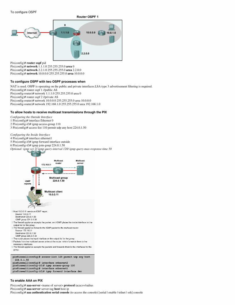
To configure OSPF
Pix(config)# router ospf pid
Pix(config)# network 1.1.1.0 255.255.255.0 area 0
Pix(config)# network 2.2.1.0 255.255.255.0 area 2.2.0.0
Pix(config)# network 10.0.0.0 255.255.255.0 area 10.0.0.0
To configure OSPF with two OSPF processes when
NAT is used. OSPF is operating on the public and private interfaces.LSA type 3 advertisement filtering is required.
Pix(config)# router ospf 1 //public AS
Pix(config-router)# network 1.1.1.0 255.255.255.0 area 0
Pix(config)# router ospf 2 //private AS
Pix(config-router)# network 10.0.0.0 255.255.255.0 area 10.0.0.0
Pix(config-router)# network 192.168.1.0 255.255.255.0 area 192.168.1.0
To allow hosts to receive multicast transmissions through the PIX
Configuring the Outside Interface
1 Pix(config)# interface Ethernet 0
2 Pix(config-if)# igmp access-group 110
3 Pix(config)# access-list 110 permit udp any host 224.0.1.50
Configuring the Inside Interface
4 Pix(config)# interface ethernet1
5 Pix(config-if)# igmp forward interface outside
6 Pix(config-if)# igmp join-goup 224.0.1.50
Optional: igmp ver 2/ igmp query-interval 120/ igmp query-max-response-time 50
To enable AAA on PIX
Pix(config)# aaa-server <name of server> protocol tacacs+/radius
Pix(config)# aaa-server server-tag host host ip
Pix(config)# aaa authentication serial console (to access the console) [serial | enable | telnet | ssh] console
Pix(config)# username admin password cisco
Pix(config)# aaa authentication telnet console local
Pix(config)# aaa local authentication attempts max-fail # of tries
Pix(config)# auth-prompt prompt Please Authenticate
Pix(config)# auth-prompt reject Authentication Failed
Pix(config)# auth-prompt accept Login successful
Pix(config)# timeout uauth 3:00:00 absolute (from time at login)
Pix(config)# timeout uauth 0:30:00 inactivity (when traffic stops)
Pix(config)# radius-server key string (specifys aaa group)
Block Active X / Java
Pix(config)# filter activex 80 0.0.0.0 0.0.0.0. 0.0.0.0. 0.0.0.0.
Pix(config)# filter java 80 0.0.0.0 0.0.0.0. 0.0.0.0. 0.0.0.0.
URL filtering
Pix(config)# url-server (interface) host [ip of websense server] timeout 10 protocol TCP version 4
Pix(config)# filter url http 0 0 0 0 allow (the allow says if websense server goes down, allow…if not
Filtering http/https/ftp 6.3 and later
Pix(config)# filter https 0 0 0 0 allow
Pix ACL’s
Pix(config)# access-list DMZ1 deny tcp 192.168.1.0 255.255.255.0 host 192.168.0.1 lt 1025
(denies access from the 1.0 network to tcp ports less than 1025 to DMZ host 0.1)
Pix(config)# access-group DMZ1 in interface dmz
(binds ACL DMZ1 to interface dmz)
Pix(config)# Access-list NONAT permit ip host 10.0.0.11 host 10.2.1.3
Pix(config)# nat (inside) 0 access-list NONAT
(allows the ACL to define traffic that is to be excluded from the NAT process)
Pix(config)# show access-list
Pix(config)# clear access-list
Pix(config)# no access-list
Pix(config)# access-list mode auto-commit|manual-commit
(auto= any acl entered will take effect immediately…. Manual= any acl entered will take effect when the access-list commit command is used.)
Pix(config)# access-list DMZ1 line 2 permit tcp any host 192.168.0.1 eq www
(inserts a new line into exsisting acl. This line will now be 2 and line 2 in the list will now be 3)
In order to Ping:
pixfirewall(config)# conduit permit icmp any any
or
pixfirewall(config)# icmp deny any echo outside (all pings denied at outside int)
pixfirewall(config)# icmp permit any unreachable outside (all unreachable allowed at outside int)
VPN ACL’s
pixfirewall(config)# access-list [name of acl] permit ip [source/snm] [destination/snm]
pixfirewall(config)# nat (inside) 0 access-list [name of acl for vpn]
Turbo ACL
Sorts acl’s over 19 entries long into table for faster processing
pixfirewall(config)# access-list compiled (all acl’s will be scanned)
pixfirewall(config)# access-list [acl name] (only that acl will be compiled)
Configure Groups for ACLs
Usage: [no] object-group protocol | network | icmp-type <obj_grp_id>
[no] object-group service <obj_grp_id> tcp|udp|tcp-udp
show object-group [protocol | service | icmp-type | network]
show object-group id <obj_grp_id>
clear object-group [protocol | service | icmp-type | network]
Contexts
pixfirewall(config)# show mode ( mult or single. Flash mode is the same as running mode)
pixfirewall(config)# mode {single | multiple} [noconfirm] (noconfirm sets mode w/o promting, wr mem first)
pixfirewall(config)# context name (adds the context)
pixfirewall(config-ctx)# allocate-interface gigabitethernet 0/1 (must enable interface in config first. Initial context has no int’s)
pixfirewall(config-ctx)# config-url [disk0/flash (stored in flash), disk1 (stored on compact flash card), tftp (tftp server), ftp, http(s) (webserver-read only)
example: pixfirewall(config-ctx)# config-url disk0:/context3.cfg (wr mem saves to the config url specified now.)
pixfirewall(config)# no context nameofcontext (removes the context)
pixfirewall(config)# clear configure context (removes all context including admin)
pixfirewall(config)# admin-context name (sets any context to the admin)
pixfirewall(config)# changeto {system | context name} (changes environment)
pixfirewall(config)# show context name [detail]
Failover-Serial cable-Active/Standby
Step 1 Attach a network cable for each network interface that is planned to be used.
Step 2 Connect the failover cable between the primary PIX Security Appliance and the secondary PIX.
Step 3 Configure the following failover parameters on the PIX Security Appliance. When this configuration is finished, save it to the Flash memory of the primary
unit.
1. Failover
2. Standby IP addresses
3. Stateful failover interface. This is optional, for use with stateful failover.
4. Failover poll time (optional).
Step 4 Power on the secondary PIX Security Appliance.
Failover-Lan based
Step 1 Install a LAN-based failover connection between the two PIX Security Appliances. Verify that any switch port that connects to a PIX interface is configured
to support LAN-based failover. Disconnect the secondary PIX.
Step 2 Configure the primary PIX Security Appliance for failover.
Step 3 Save the configuration of the primary unit to Flash memory.
Step 4 Power on the secondary PIX Security Appliance.
Step 5 Configure the secondary PIX Security Appliance with the LAN-based failover command set.
Step 6 Save the configuration of the secondary unit to Flash memory.
Step 7 Connect the PIX Security Appliance LAN-based failover interface to the network.
Step 8 Reboot the secondary unit.
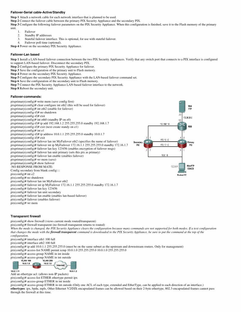
Failover-commands:
pixprimary(config)# write mem (save config first)
pixprimary(config)# clear configure int eth2 (this will be used for failover)
pixprimary(config)# int eth2 (enable for failover)
pixprimary(config-if)# no shutdown
pixprimary(config-if)# exit
pixprimary(config)# int eth0 (standby IP on e0)
pixprimary(config-if)# ip add 192.168.1.2 255.255.255.0 standby 192.168.1.7
pixprimary(config-if)# exit (next create standy on e1)
pixprimary(config)# int e1
pixprimary(config-if)# ip address 10.0.1.1 255.255.255.0 standby 10.0.1.7
pixprimary(config-if)# exit
pixprimary(config)# failover lan int MyFailover eth2 (specifies the name of failover)
pixprimary(config)# failover int ip MyFailover 172.16.1.1 255.255.255.0 standby 172.16.1.7
pixprimary(config)# failover lan key 123456 (enables encryption of failover msgs)
pixprimary(config)# failover lan unit primary (sets this pix as primary)
pixprimary(config)# failover lan enable (enables failover)
pixprimary(config)# wr mem (save)
pixprimary(config)# show failover
:NO RESPONSE FROM MATE:
Config secondary from blank config::::
pix(config)# int e2
pix(config)# no shutdown
pix(config)# failover lan int MyFailover eth2
pix(config)# failover int ip MyFailover 172.16.1.1 255.255.255.0 standby 172.16.1.7
pix(config)# failover lan key 123456
pix(config)# failover lan unit secondary
pix(config)# failover lan enable (enables lan-based failover)
pix(config)# failover (enables failover)
pix(config)# wr mem
Transparent firewall
pix(config)# show firewall (views current mode routed/transparent)
pix(config)# firewall transparent (no firewall transparent returns to routed) When the mode is changed, the PIX Security Appliance clears the configuration because many commands are not supported for both modes. If a text configuration
that changes the mode with the firewall transparent command is downloaded to the PIX Security Appliance, be sure to put the command at the top of the
configuration.
pix(config)# interface eth1 100 full
pix(config)# interface eth2 100 full
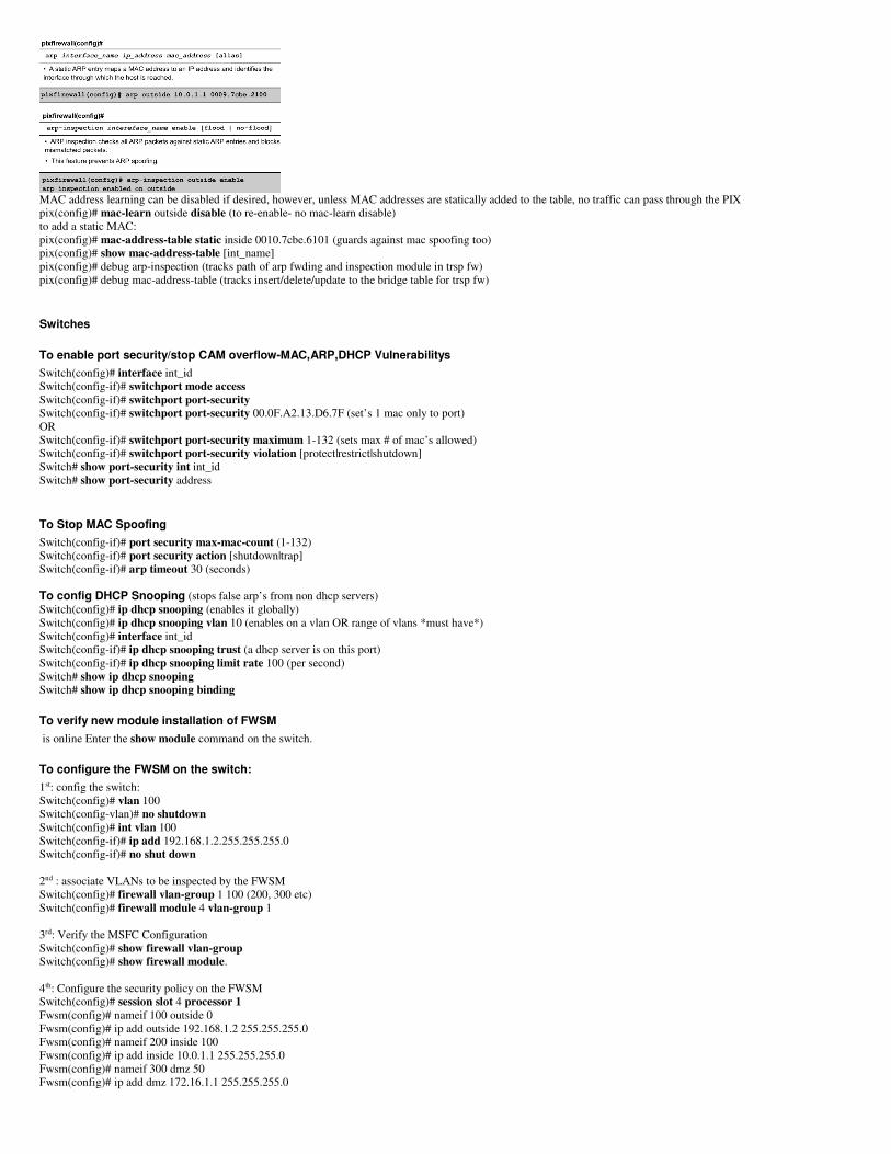
pix(config)# ip add 10.0.1.1 255.255.255.0 (must be on the same subnet as the upstream and downstream routers. Only for management)
pix(config)# access-list NAME permit icmp 10.0.1.0 255.255.255.0 10.0.1.0 255.255.255.0
pix(config)# access-group NAME in int inside
pix(config)# access-group NAME in int outside
Add an ethertype acl: (allows non-IP packets)
pix(config)# access-list ETHER ethertype permit ipx
pix(config)# access-group ETHER in int inside
pix(config)# access-group ETHER in int outside (Only one ACL of each type, extended and EtherType, can be applied to each direction of an interface.)
ethertypes: ipx, bpdu, mpls, Other Ethernet V2/DIX-encapsulated frames can be allowed based on their 2-byte ethertype, 802.3-encapsulated frames cannot pass
through the firewall at this time.
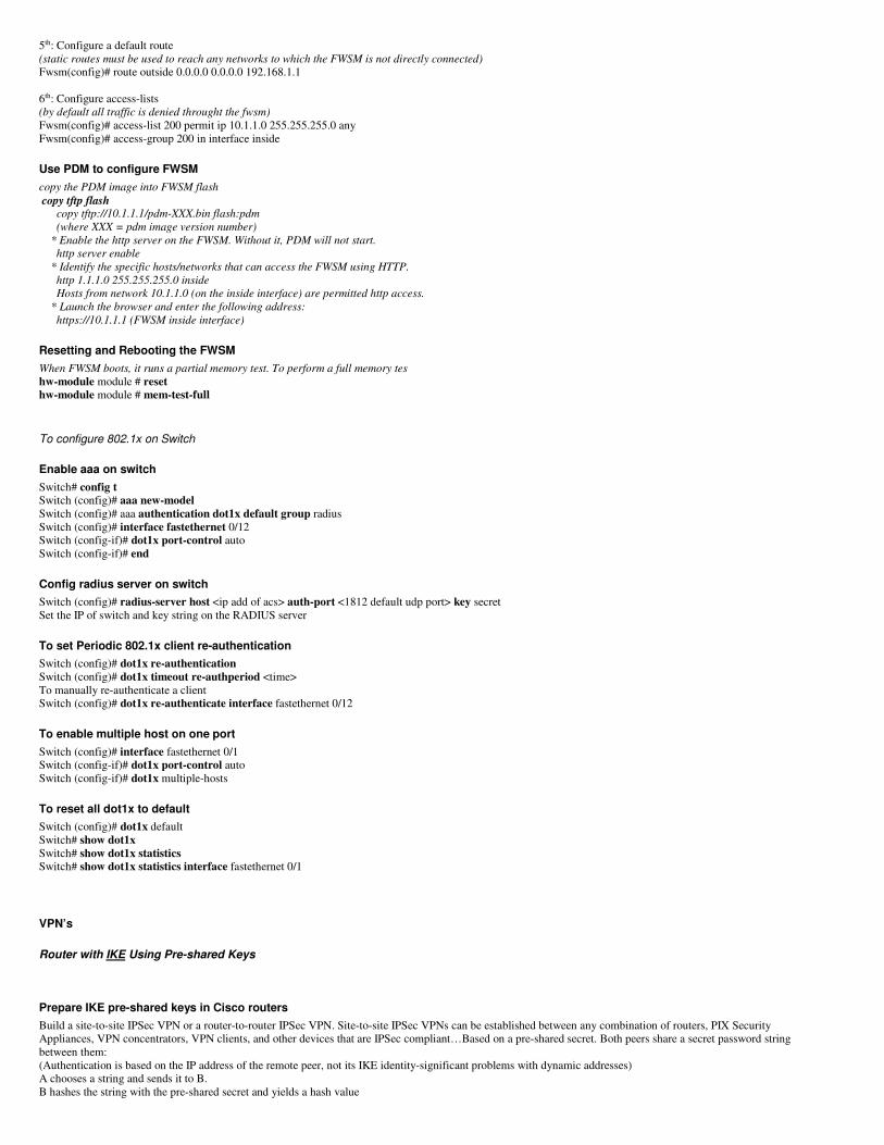
MAC address learning can be disabled if desired, however, unless MAC addresses are statically added to the table, no traffic can pass through the PIX
pix(config)# mac-learn outside disable (to re-enable- no mac-learn disable)
to add a static MAC:
pix(config)# mac-address-table static inside 0010.7cbe.6101 (guards against mac spoofing too)
pix(config)# show mac-address-table [int_name]
pix(config)# debug arp-inspection (tracks path of arp fwding and inspection module in trsp fw)
pix(config)# debug mac-address-table (tracks insert/delete/update to the bridge table for trsp fw)
Switches
To enable port security/stop CAM overflow-MAC,ARP,DHCP Vulnerabilitys
Switch(config)# interface int_id
Switch(config-if)# switchport mode access
Switch(config-if)# switchport port-security
Switch(config-if)# switchport port-security 00.0F.A2.13.D6.7F (set’s 1 mac only to port)
OR
Switch(config-if)# switchport port-security maximum 1-132 (sets max # of mac’s allowed)
Switch(config-if)# switchport port-security violation [protect|restrict|shutdown]
Switch# show port-security int int_id
Switch# show port-security address
To Stop MAC Spoofing
Switch(config-if)# port security max-mac-count (1-132)
Switch(config-if)# port security action [shutdown|trap]
Switch(config-if)# arp timeout 30 (seconds)
To config DHCP Snooping (stops false arp’s from non dhcp servers)
Switch(config)# ip dhcp snooping (enables it globally)
Switch(config)# ip dhcp snooping vlan 10 (enables on a vlan OR range of vlans *must have*)
Switch(config)# interface int_id
Switch(config-if)# ip dhcp snooping trust (a dhcp server is on this port)
Switch(config-if)# ip dhcp snooping limit rate 100 (per second)
Switch# show ip dhcp snooping
Switch# show ip dhcp snooping binding
To verify new module installation of FWSM
is online Enter the show module command on the switch.
To configure the FWSM on the switch:
1st: config the switch:
Switch(config)# vlan 100
Switch(config-vlan)# no shutdown
Switch(config)# int vlan 100
Switch(config-if)# ip add 192.168.1.2.255.255.255.0
Switch(config-if)# no shut down
2nd : associate VLANs to be inspected by the FWSM
Switch(config)# firewall vlan-group 1 100 (200, 300 etc)
Switch(config)# firewall module 4 vlan-group 1
3rd: Verify the MSFC Configuration
Switch(config)# show firewall vlan-group
Switch(config)# show firewall module.
4th: Configure the security policy on the FWSM
Switch(config)# session slot 4 processor 1
Fwsm(config)# nameif 100 outside 0
Fwsm(config)# ip add outside 192.168.1.2 255.255.255.0
Fwsm(config)# nameif 200 inside 100
Fwsm(config)# ip add inside 10.0.1.1 255.255.255.0
Fwsm(config)# nameif 300 dmz 50
Fwsm(config)# ip add dmz 172.16.1.1 255.255.255.0
5th: Configure a default route
(static routes must be used to reach any networks to which the FWSM is not directly connected)
Fwsm(config)# route outside 0.0.0.0 0.0.0.0 192.168.1.1
6th: Configure access-lists
(by default all traffic is denied throught the fwsm)
Fwsm(config)# access-list 200 permit ip 10.1.1.0 255.255.255.0 any
Fwsm(config)# access-group 200 in interface inside
Use PDM to configure FWSM
copy the PDM image into FWSM flash
copy tftp flash copy tftp://10.1.1.1/pdm-XXX.bin flash:pdm
(where XXX = pdm image version number)
* Enable the http server on the FWSM. Without it, PDM will not start.
http server enable
* Identify the specific hosts/networks that can access the FWSM using HTTP.
http 1.1.1.0 255.255.255.0 inside
Hosts from network 10.1.1.0 (on the inside interface) are permitted http access.
* Launch the browser and enter the following address:
https://10.1.1.1 (FWSM inside interface)
Resetting and Rebooting the FWSM
When FWSM boots, it runs a partial memory test. To perform a full memory tes
hw-module module # reset
hw-module module # mem-test-full
To configure 802.1x on Switch
Enable aaa on switch
Switch# config t
Switch (config)# aaa new-model
Switch (config)# aaa authentication dot1x default group radius
Switch (config)# interface fastethernet 0/12
Switch (config-if)# dot1x port-control auto
Switch (config-if)# end
Config radius server on switch
Switch (config)# radius-server host <ip add of acs> auth-port <1812 default udp port> key secret
Set the IP of switch and key string on the RADIUS server
To set Periodic 802.1x client re-authentication
Switch (config)# dot1x re-authentication
Switch (config)# dot1x timeout re-authperiod <time>
To manually re-authenticate a client
Switch (config)# dot1x re-authenticate interface fastethernet 0/12
To enable multiple host on one port
Switch (config)# interface fastethernet 0/1
Switch (config-if)# dot1x port-control auto
Switch (config-if)# dot1x multiple-hosts
To reset all dot1x to default
Switch (config)# dot1x default
Switch# show dot1x
Switch# show dot1x statistics
Switch# show dot1x statistics interface fastethernet 0/1
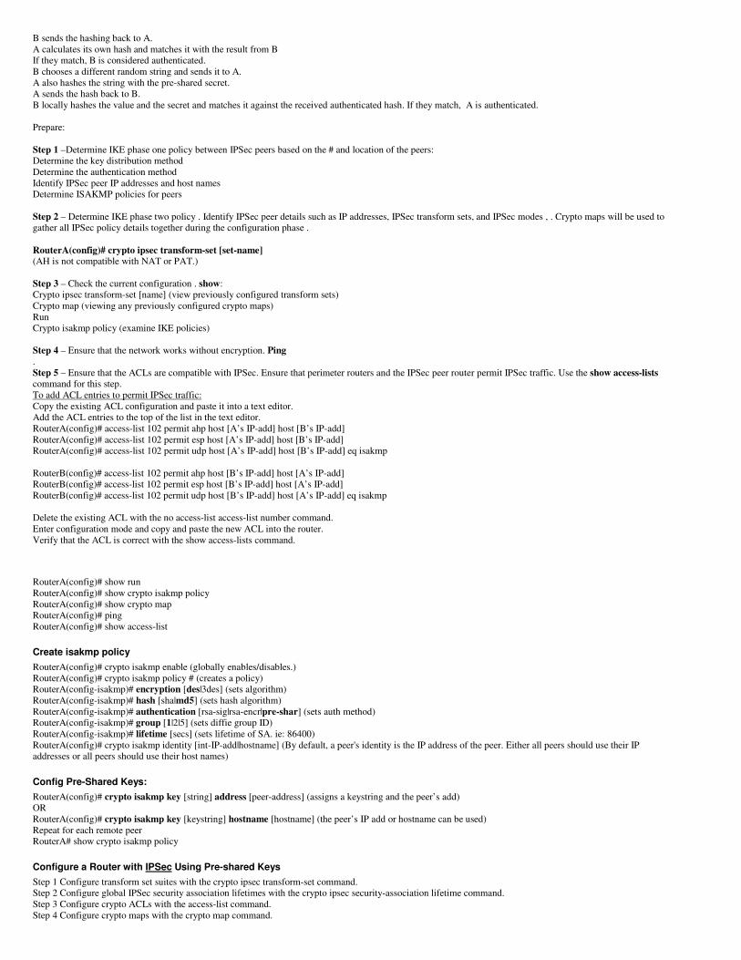
VPN’s
Router with IKE Using Pre-shared Keys
Prepare IKE pre-shared keys in Cisco routers
Build a site-to-site IPSec VPN or a router-to-router IPSec VPN. Site-to-site IPSec VPNs can be established between any combination of routers, PIX Security
Appliances, VPN concentrators, VPN clients, and other devices that are IPSec compliant…Based on a pre-shared secret. Both peers share a secret password string
between them:
(Authentication is based on the IP address of the remote peer, not its IKE identity-significant problems with dynamic addresses)
A chooses a string and sends it to B.
B hashes the string with the pre-shared secret and yields a hash value
B sends the hashing back to A.
A calculates its own hash and matches it with the result from B
If they match, B is considered authenticated.
B chooses a different random string and sends it to A.
A also hashes the string with the pre-shared secret.
A sends the hash back to B.
B locally hashes the value and the secret and matches it against the received authenticated hash. If they match, A is authenticated.
Prepare:
Step 1 –Determine IKE phase one policy between IPSec peers based on the # and location of the peers:
Determine the key distribution method
Determine the authentication method
Identify IPSec peer IP addresses and host names
Determine ISAKMP policies for peers
Step 2 – Determine IKE phase two policy . Identify IPSec peer details such as IP addresses, IPSec transform sets, and IPSec modes , . Crypto maps will be used to
gather all IPSec policy details together during the configuration phase .
RouterA(config)# crypto ipsec transform-set [set-name] (AH is not compatible with NAT or PAT.)
Step 3 – Check the current configuration . show:
Crypto ipsec transform-set [name] (view previously configured transform sets)
Crypto map (viewing any previously configured crypto maps)
Run
Crypto isakmp policy (examine IKE policies)
Step 4 – Ensure that the network works without encryption. Ping
.
Step 5 – Ensure that the ACLs are compatible with IPSec. Ensure that perimeter routers and the IPSec peer router permit IPSec traffic. Use the show access-lists
command for this step.
To add ACL entries to permit IPSec traffic:
Copy the existing ACL configuration and paste it into a text editor.
Add the ACL entries to the top of the list in the text editor.
RouterA(config)# access-list 102 permit ahp host [A’s IP-add] host [B’s IP-add]
RouterA(config)# access-list 102 permit esp host [A’s IP-add] host [B’s IP-add]
RouterA(config)# access-list 102 permit udp host [A’s IP-add] host [B’s IP-add] eq isakmp
RouterB(config)# access-list 102 permit ahp host [B’s IP-add] host [A’s IP-add]
RouterB(config)# access-list 102 permit esp host [B’s IP-add] host [A’s IP-add]
RouterB(config)# access-list 102 permit udp host [B’s IP-add] host [A’s IP-add] eq isakmp
Delete the existing ACL with the no access-list access-list number command.
Enter configuration mode and copy and paste the new ACL into the router.
Verify that the ACL is correct with the show access-lists command.
RouterA(config)# show run
RouterA(config)# show crypto isakmp policy
RouterA(config)# show crypto map
RouterA(config)# ping
RouterA(config)# show access-list
Create isakmp policy
RouterA(config)# crypto isakmp enable (globally enables/disables.)
RouterA(config)# crypto isakmp policy # (creates a policy)
RouterA(config-isakmp)# encryption [des|3des] (sets algorithm)
RouterA(config-isakmp)# hash [sha|md5] (sets hash algorithm)
RouterA(config-isakmp)# authentication [rsa-sig|rsa-encr|pre-shar] (sets auth method)
RouterA(config-isakmp)# group [1|2|5] (sets diffie group ID)
RouterA(config-isakmp)# lifetime [secs] (sets lifetime of SA. ie: 86400)
RouterA(config)# crypto isakmp identity [int-IP-add|hostname] (By default, a peer's identity is the IP address of the peer. Either all peers should use their IP
addresses or all peers should use their host names)
Config Pre-Shared Keys:
RouterA(config)# crypto isakmp key [string] address [peer-address] (assigns a keystring and the peer’s add)
OR
RouterA(config)# crypto isakmp key [keystring] hostname [hostname] (the peer’s IP add or hostname can be used)
Repeat for each remote peer
RouterA# show crypto isakmp policy
Configure a Router with IPSec Using Pre-shared Keys
Step 1 Configure transform set suites with the crypto ipsec transform-set command.
Step 2 Configure global IPSec security association lifetimes with the crypto ipsec security-association lifetime command.
Step 3 Configure crypto ACLs with the access-list command.
Step 4 Configure crypto maps with the crypto map command.
Step 5 Apply the crypto maps to the terminating/originating interface with the interface and crypto map commands.
Configure transform set suites
During IPSec security association negotiations with IKE, the peers search for a transform set that is the same at both peers.
RouterA(config)# crypto ipsec transform-set [name] [transoform1|trans2|trans3] (defines set.)
RouterA(cfg-crypto-trans)# mode [tunnel | transport] (optional: changes mode of trans set only applicable to traffic whose src and dst are the IPSec peer add.)
To edit a Transform Set:
Config trans set suites
Delete the trans set from crypto map
Delete trans set from global config
Reenter the trans set
Assign the set to a crypto map
Clear SA DB
To force the new settings to take effect
RouterA(config)# clear crypto sa
Configure global IPSec SA lifetimes
only apply to security associations established via IKE-- default -3,600 seconds, and 4,608,000 kilobytes per/hour.
routerA(config)# crypto ipsec security-association lifetime [secs|kilobytes bytes]( configs global SA lifetime. Crypto maps lifetimes will override these)
To use the new values immediately
routerA(config)# clear crypto sa (Associations established manually, marked as ipsec-manual, have an infinite lifetime.)
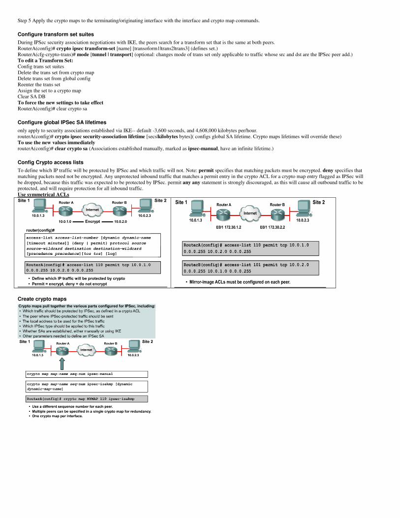
Config Crypto access lists
To define which IP traffic will be protected by IPSec and which traffic will not. Note: permit specifies that matching packets must be encrypted. deny specifies that
matching packets need not be encrypted. Any unprotected inbound traffic that matches a permit entry in the crypto ACL for a crypto map entry flagged as IPSec will
be dropped, because this traffic was expected to be protected by IPSec. permit any any statement is strongly discouraged, as this will cause all outbound traffic to be
protected, and will require protection for all inbound traffic.
Use symmetrical ACLs
Create crypto maps
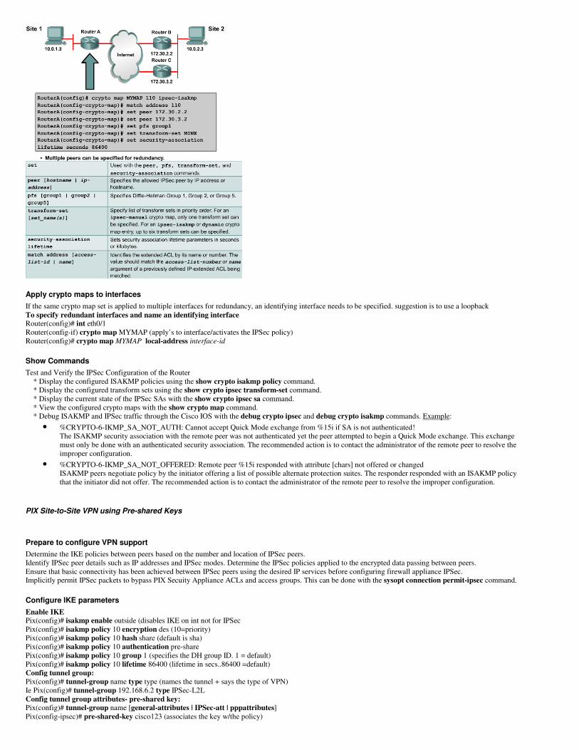
Apply crypto maps to interfaces
If the same crypto map set is applied to multiple interfaces for redundancy, an identifying interface needs to be specified. suggestion is to use a loopback
To specify redundant interfaces and name an identifying interface Router(config)# int eth0/1
Router(config-if) crypto map MYMAP (apply’s to interface/activates the IPSec policy)
Router(config)# crypto map MYMAP local-address interface-id
Show Commands
Test and Verify the IPSec Configuration of the Router
* Display the configured ISAKMP policies using the show crypto isakmp policy command.
* Display the configured transform sets using the show crypto ipsec transform-set command.
* Display the current state of the IPSec SAs with the show crypto ipsec sa command.
* View the configured crypto maps with the show crypto map command.
* Debug ISAKMP and IPSec traffic through the Cisco IOS with the debug crypto ipsec and debug crypto isakmp commands. Example:
• %CRYPTO-6-IKMP_SA_NOT_AUTH: Cannot accept Quick Mode exchange from %15i if SA is not authenticated!
The ISAKMP security association with the remote peer was not authenticated yet the peer attempted to begin a Quick Mode exchange. This exchange
must only be done with an authenticated security association. The recommended action is to contact the administrator of the remote peer to resolve the
improper configuration.
• %CRYPTO-6-IKMP_SA_NOT_OFFERED: Remote peer %15i responded with attribute [chars] not offered or changed
ISAKMP peers negotiate policy by the initiator offering a list of possible alternate protection suites. The responder responded with an ISAKMP policy
that the initiator did not offer. The recommended action is to contact the administrator of the remote peer to resolve the improper configuration.
PIX Site-to-Site VPN using Pre-shared Keys
Prepare to configure VPN support
Determine the IKE policies between peers based on the number and location of IPSec peers.
Identify IPSec peer details such as IP addresses and IPSec modes. Determine the IPSec policies applied to the encrypted data passing between peers.
Ensure that basic connectivity has been achieved between IPSec peers using the desired IP services before configuring firewall appliance IPSec.
Implicitly permit IPSec packets to bypass PIX Secuity Appliance ACLs and access groups. This can be done with the sysopt connection permit-ipsec command.
Configure IKE parameters
Enable IKE Pix(config)# isakmp enable outside (disables IKE on int not for IPSec
Pix(config)# isakmp policy 10 encryption des (10=priority)
Pix(config)# isakmp policy 10 hash share (default is sha)
Pix(config)# isakmp policy 10 authentication pre-share
Pix(config)# isakmp policy 10 group 1 (specifies the DH group ID. 1 = default)
Pix(config)# isakmp policy 10 lifetime 86400 (lifetime in secs..86400 =default)
Config tunnel group:
Pix(config)# tunnel-group name type type (names the tunnel + says the type of VPN)
Ie Pix(config)# tunnel-group 192.168.6.2 type IPSec-L2L
Config tunnel group attributes- pre-shared key:
Pix(config)# tunnel-group name [general-attributes | IPSec-att | pppattributes]
Pix(config-ipsec)# pre-shared-key cisco123 (associates the key w/the policy)
Verify IKE policies
Pix# show run crypto isakmp (displays configured and default policies)
Pix# show run tunnel-group (displays tunnel group information about all or a specified tunnel group and tunnel group attributes)
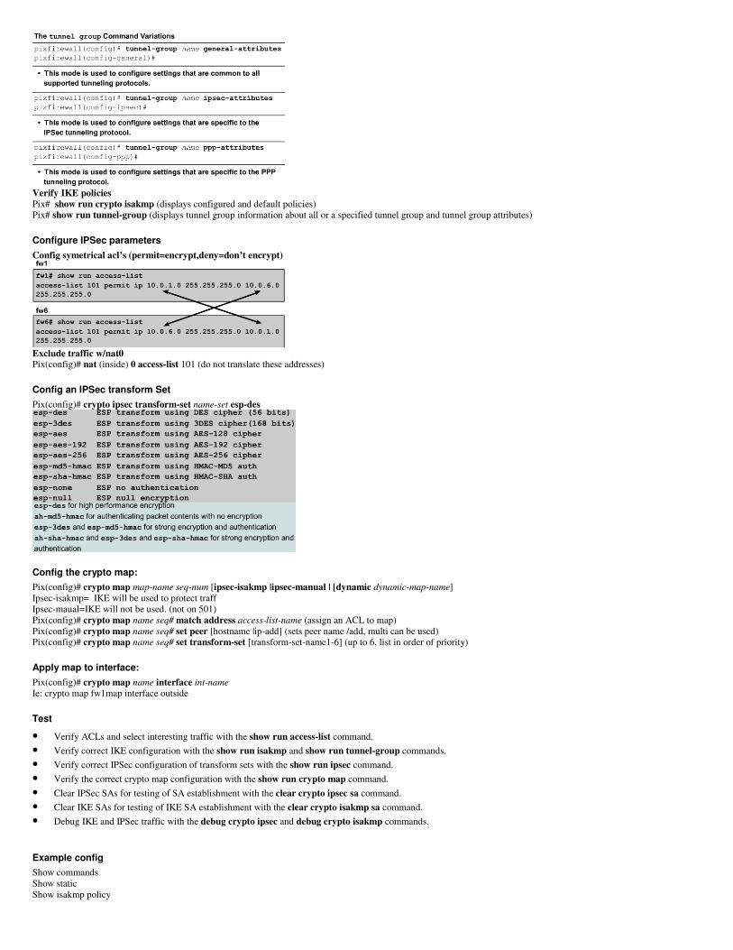
Configure IPSec parameters
Config symetrical acl’s (permit=encrypt,deny=don’t encrypt)
Exclude traffic w/nat0 Pix(config)# nat (inside) 0 access-list 101 (do not translate these addresses)
Config an IPSec transform Set
Pix(config)# crypto ipsec transform-set name-set esp-des
Config the crypto map:
Pix(config)# crypto map map-name seq-num [ipsec-isakmp |ipsec-manual | [dynamic dynamic-map-name]
Ipsec-isakmp= IKE will be used to protect traff
Ipsec-maual=IKE will not be used. (not on 501)
Pix(config)# crypto map name seq# match address access-list-name (assign an ACL to map)
Pix(config)# crypto map name seq# set peer [hostname |ip-add] (sets peer name /add, multi can be used)
Pix(config)# crypto map name seq# set transform-set [transform-set-name1-6] (up to 6, list in order of priority)
Apply map to interface:
Pix(config)# crypto map name interface int-name
Ie: crypto map fw1map interface outside
Test
• Verify ACLs and select interesting traffic with the show run access-list command.
• Verify correct IKE configuration with the show run isakmp and show run tunnel-group commands.
• Verify correct IPSec configuration of transform sets with the show run ipsec command.
• Verify the correct crypto map configuration with the show run crypto map command.
• Clear IPSec SAs for testing of SA establishment with the clear crypto ipsec sa command.
• Clear IKE SAs for testing of IKE SA establishment with the clear crypto isakmp sa command.
• Debug IKE and IPSec traffic with the debug crypto ipsec and debug crypto isakmp commands.
Example config
Show commands
Show static
Show isakmp policy
Pix2(config)# access-list 102 permit ah host 1.1.1.1 host 1.1.1.2
Pix2(config)# access-list 102 permit esp host 1.1.1.1 host 1.1.1.2
Pix2(config)# access-list 102 permit udp host 1.1.1.1 host 1.1.1.2 eq isakmp
Pix2(config)# sysopt connection permit-ipsec
Pix2(config)# isakmp enable outside
Pix2(config)# isakmp policy 10 authentication pre-share
Pix2(config)# isakmp policy 10 encrypt des
Pix2(config)# isakmp policy 10 hash md5
Pix2(config)# isakmp policy 10 group 1
Pix2(config)# isakmp policy 10 lifetime 86400
Pix2(config)# isakmp identity address
Pix2(config)# name 1.1.1.1 Pix1
Pix2(config)# isakmp key cisco123 address 1.1.1.1 netmask 255.255.255.255
Pix2(config)# crypto ipsec transform-set MYIPSEC esp-des
Pix2(config)# static (inside,outside) 1.1.1.5 192.168.2.5 netmask 255.255.255.255
Pix2(config)# access-list 102 permit ip host 1.1.1.5 host 1.1.1.5
Pix2(config)# crypto map MYMAP 10 ipsec-isakmp
Pix2(config)# crypto map MYMAP 10 match address 102
WARNING: access-list has port selectors may have performance impact
Pix2(config)# crypto map MYMAP 10 set peer 1.1.1.1
Pix2(config)# crypto map MYMAP 10 set transform-set MYIPSEC
Pix2(config)# crypto map MYMAP interface outside
Router Site to Site VPN using Digital Certificates
Basic steps:
manage NVRAM (date/time)
set router time and date
a. router(config)#clock timezone zone hours [mins]
b. router(config)#clock set hh:mm:ss day month year or
c. router(config)#clock set hh:mm:ss month day year
The router can optionally be set to automatically update the calendar and time from a Network Time Protocol (NTP) server with the ntp series of
commands.
config hostname and domain name
d. router(config)#hostname name
e. router(config)#ip domain-name name
f. router(config)#ip host name ip-add-of-CAserver (if domain name is not resolvable)
To define a default domain name that the Cisco IOS software uses to complete unqualified hostnames use the ip domain-name global configuration
command. Unqualified names are names without a dotted-decimal domain name
generate RSA key pair
g. router(config)#crypto key generate rsa [general-keys | usage-keys]
using the keyword ‘usage-keys’ generates two sets of rsa keys. Use on set for rsa signatures and rsa encrypted nonces. 512 = default bits 1024=
recommended.
Declare a CA
Note that in 12.3(7)T, crypto pki trustpoint replaces the crypto ca trustpoint command from previous Cisco IOS software releases. The crypto ca
trustpoint command can be entered, but the command will be written in the configuration as crypto pki trustpoint.
h. Router(config)# crypto pki trustpoint name (will allow the router to re-enroll to the CA server automatically when its certificates expire)
i. Router(ca-trustpoint)# enrollment url http://vpnca/certsrv/mscep/mscep.dll
j. Router(ca-trustpoint)# enrollment mode ra
k. Router(ca-trustpoint)# crl optional
This example declares an Entrust CA and identifies characteristics of the CA. In this example, the name vpnca is created for the CA, which is
located at http://vpnca. The example also declares a CA using an RA. The scripts for the CA are stored in the default location, and the CA uses
SCEP instead of LDAP. This is the minimum possible configuration required to declare a CA that uses an RA. Note that the enrollment URL points
to the MSCEP DLL.
Authenticate the CA
To get the public key of the CA, use the crypto pki authenticatename command in global configuration mode. Use the same name that was used when
declaring the CA with the crypto pki trustpoint command in step 5.
l. Router(config)# crypto pki authenticate name
Request a certificate for the router.
m. Router(config)# crypto pki enroll name (request signed certificates from the CA)
Save the config
n. Router# wr
Use the copy system:running-config nvram:startup-config command to save the configuration. This command includes saving RSA keys to
private NVRAM. RSA keys are not saved with the configuration when a copy system:running-config rcp: or copy system:running-config tftp:
command is issued.
optional: monitor and maintain CA interoperability
o. crypto pki trustpoint name
Verify config
p. Show crypto pki certificates
q. Show crypto key mypubkey | pubkey-chain
To specify that certificates and CRLs should not be stored locally on the router, but should be retrieved when required, turn on query mode by using the crypto ca
certificate query If query mode is turned on initially, it can turned off later. If query mode is turned off later, the copy system:running-config nvram:startup-config command can
be issued beforehand to save all current certificates and CRLs to NVRAM.
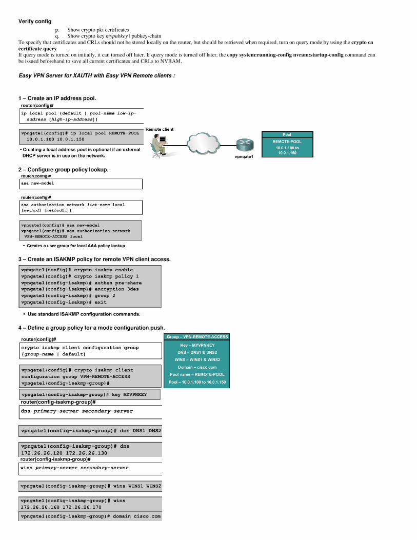
Easy VPN Server for XAUTH with Easy VPN Remote clients :
1 – Create an IP address pool.
2 – Configure group policy lookup.
3 – Create an ISAKMP policy for remote VPN client access.
4 – Define a group policy for a mode configuration push.
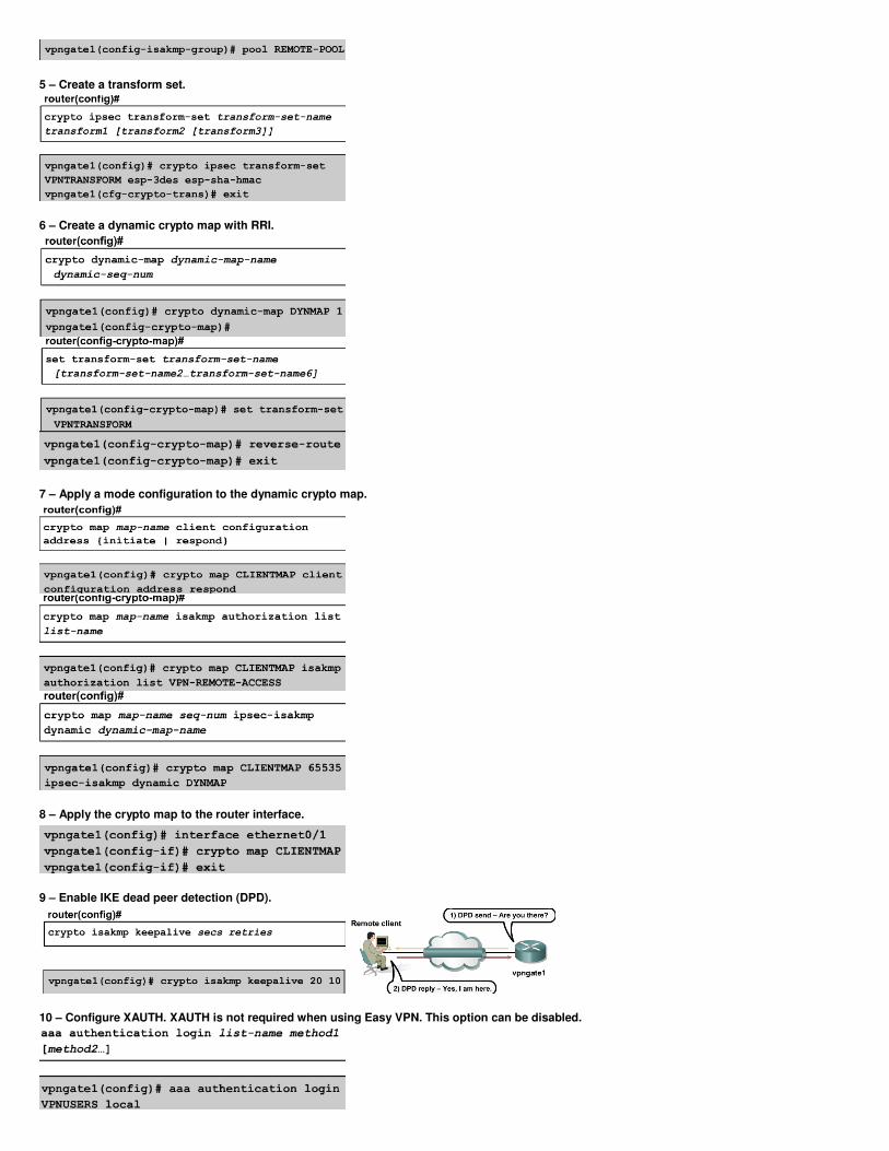
5 – Create a transform set.
6 – Create a dynamic crypto map with RRI.
7 – Apply a mode configuration to the dynamic crypto map.
8 – Apply the crypto map to the router interface.
9 – Enable IKE dead peer detection (DPD).
10 – Configure XAUTH. XAUTH is not required when using Easy VPN. This option can be disabled.
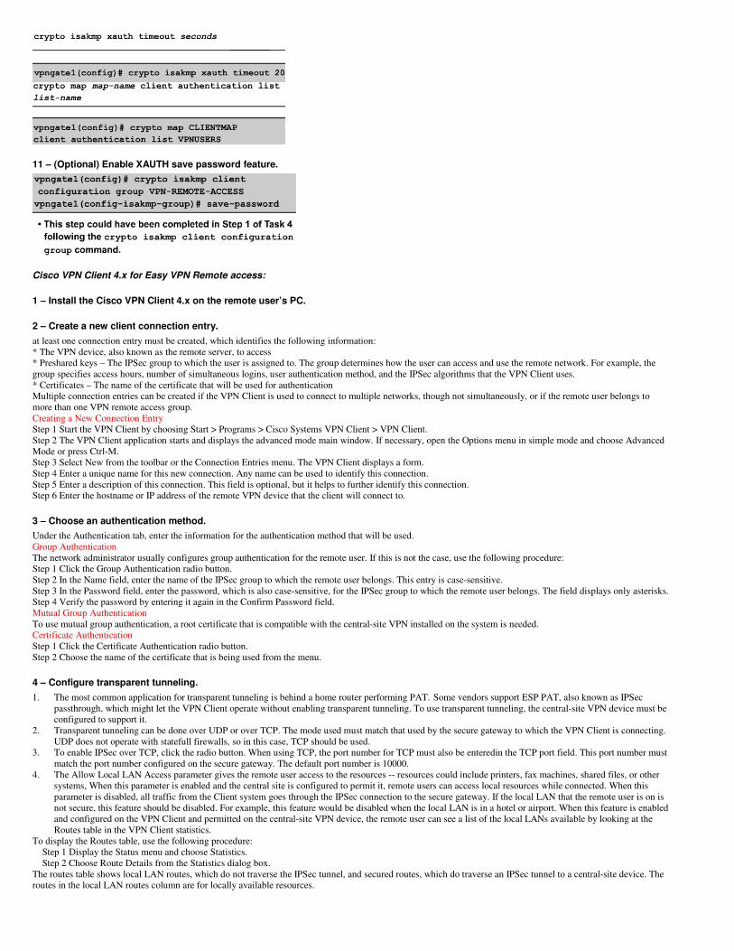
11 – (Optional) Enable XAUTH save password feature.
Cisco VPN Client 4.x for Easy VPN Remote access:
1 – Install the Cisco VPN Client 4.x on the remote user’s PC.
2 – Create a new client connection entry.
at least one connection entry must be created, which identifies the following information:
* The VPN device, also known as the remote server, to access
* Preshared keys – The IPSec group to which the user is assigned to. The group determines how the user can access and use the remote network. For example, the
group specifies access hours, number of simultaneous logins, user authentication method, and the IPSec algorithms that the VPN Client uses.
* Certificates – The name of the certificate that will be used for authentication
Multiple connection entries can be created if the VPN Client is used to connect to multiple networks, though not simultaneously, or if the remote user belongs to
more than one VPN remote access group.
Creating a New Connection Entry
Step 1 Start the VPN Client by choosing Start > Programs > Cisco Systems VPN Client > VPN Client.
Step 2 The VPN Client application starts and displays the advanced mode main window. If necessary, open the Options menu in simple mode and choose Advanced
Mode or press Ctrl-M.
Step 3 Select New from the toolbar or the Connection Entries menu. The VPN Client displays a form.
Step 4 Enter a unique name for this new connection. Any name can be used to identify this connection.
Step 5 Enter a description of this connection. This field is optional, but it helps to further identify this connection.
Step 6 Enter the hostname or IP address of the remote VPN device that the client will connect to.
3 – Choose an authentication method.
Under the Authentication tab, enter the information for the authentication method that will be used.
Group Authentication
The network administrator usually configures group authentication for the remote user. If this is not the case, use the following procedure:
Step 1 Click the Group Authentication radio button.
Step 2 In the Name field, enter the name of the IPSec group to which the remote user belongs. This entry is case-sensitive.
Step 3 In the Password field, enter the password, which is also case-sensitive, for the IPSec group to which the remote user belongs. The field displays only asterisks.
Step 4 Verify the password by entering it again in the Confirm Password field.
Mutual Group Authentication
To use mutual group authentication, a root certificate that is compatible with the central-site VPN installed on the system is needed.
Certificate Authentication
Step 1 Click the Certificate Authentication radio button.
Step 2 Choose the name of the certificate that is being used from the menu.
4 – Configure transparent tunneling.
1. The most common application for transparent tunneling is behind a home router performing PAT. Some vendors support ESP PAT, also known as IPSec
passthrough, which might let the VPN Client operate without enabling transparent tunneling. To use transparent tunneling, the central-site VPN device must be
configured to support it.
2. Transparent tunneling can be done over UDP or over TCP. The mode used must match that used by the secure gateway to which the VPN Client is connecting.
UDP does not operate with statefull firewalls, so in this case, TCP should be used.
3. To enable IPSec over TCP, click the radio button. When using TCP, the port number for TCP must also be enteredin the TCP port field. This port number must
match the port number configured on the secure gateway. The default port number is 10000.
4. The Allow Local LAN Access parameter gives the remote user access to the resources -- resources could include printers, fax machines, shared files, or other
systems, When this parameter is enabled and the central site is configured to permit it, remote users can access local resources while connected. When this
parameter is disabled, all traffic from the Client system goes through the IPSec connection to the secure gateway. If the local LAN that the remote user is on is
not secure, this feature should be disabled. For example, this feature would be disabled when the local LAN is in a hotel or airport. When this feature is enabled
and configured on the VPN Client and permitted on the central-site VPN device, the remote user can see a list of the local LANs available by looking at the
Routes table in the VPN Client statistics.
To display the Routes table, use the following procedure:
Step 1 Display the Status menu and choose Statistics.
Step 2 Choose Route Details from the Statistics dialog box.
The routes table shows local LAN routes, which do not traverse the IPSec tunnel, and secured routes, which do traverse an IPSec tunnel to a central-site device. The
routes in the local LAN routes column are for locally available resources.
5 – Enable and add backup servers.
The private network may include one or more backup VPN servers to use if the primary server is not available. The system administrator should tell the remote user
whether to enable backup servers. Information on backup servers can download automatically from the VPN Concentrator, or this information can be entered
manually.
To enable backup servers from the VPN Client, use the following procedure:
Step 1 Open the Backup Servers tab.
Step 2 Check Enable Backup Server(s). This is not checked by default.
Step 3 Click Add to enter the address of a backup server.
Step 4 Enter the hostname or IP address of the backup server. Use a maximum of 255 characters.
Step 5 To add more backup devices, repeat Steps 2, 3, and 4.
6– Configure a connection to the Internet through dial-up networking.
To connect to a private network using a dial-up connection, perform the following steps:
Step 1 Use a dial-up connection to an Internet service provider (ISP) to connect to the Internet.
Step 2 Use the VPN Client to connect to the private network through the Internet.
To enable and configure this feature, check the Connect to the Internet via dial-up check box. This feature is not checked by default.
Remote users can connect to the Internet using the VPN Client application in either of the following ways:
* Microsoft Dial-up Networking (DUN)
* Third party dial-up program
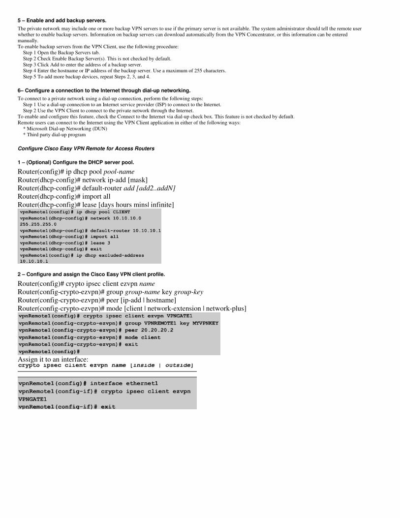
Configure Cisco Easy VPN Remote for Access Routers
1 – (Optional) Configure the DHCP server pool.
Router(config)# ip dhcp pool pool-name
Router(dhcp-config)# network ip-add [mask]
Router(dhcp-config)# default-router add [add2..addN]
Router(dhcp-config)# import all
Router(dhcp-config)# lease [days hours mins| infinite]
2 – Configure and assign the Cisco Easy VPN client profile.
Router(config)# crypto ipsec client ezvpn name
Router(config-crypto-ezvpn)# group group-name key group-key
Router(config-crypto-ezvpn)# peer [ip-add | hostname]
Router(config-crypto-ezvpn)# mode [client | network-extension | network-plus]
Assign it to an interface:
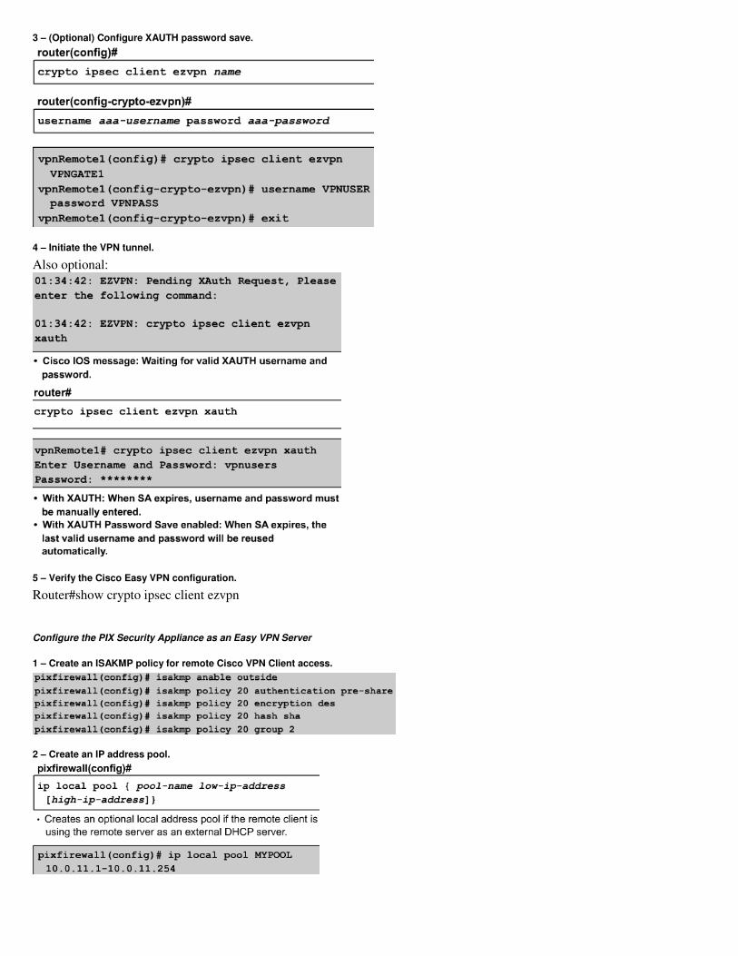
3 – (Optional) Configure XAUTH password save.
4 – Initiate the VPN tunnel.
Also optional:
5 – Verify the Cisco Easy VPN configuration.
Router#show crypto ipsec client ezvpn
Configure the PIX Security Appliance as an Easy VPN Server
1 – Create an ISAKMP policy for remote Cisco VPN Client access.
2 – Create an IP address pool.
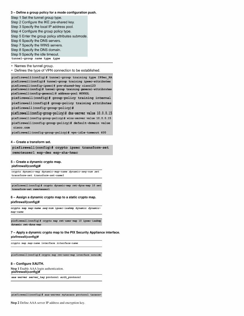
3 – Define a group policy for a mode configuration push.
4 – Create a transform set.
5 – Create a dynamic crypto map.
6 – Assign a dynamic crypto map to a static crypto map.
7 – Apply a dynamic crypto map to the PIX Security Appliance interface.
8 – Configure XAUTH.
Step 1 Enable AAA login authentication.
Step 2 Define AAA server IP address and encryption key.
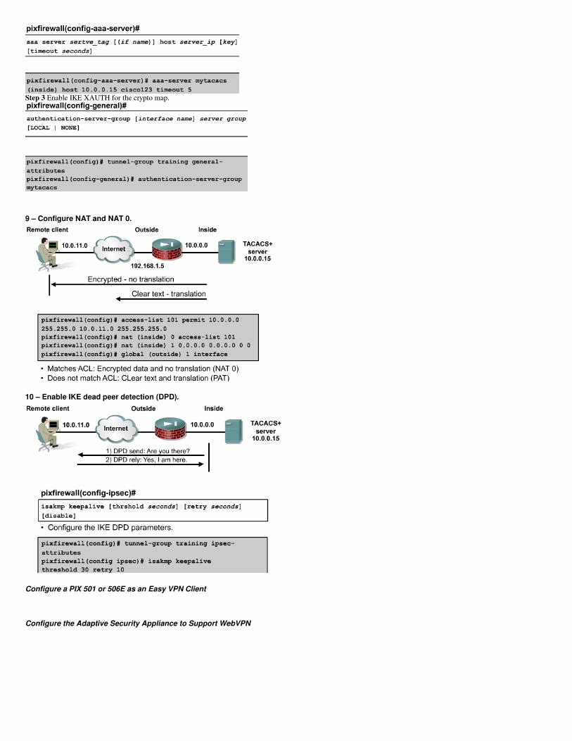
Step 3 Enable IKE XAUTH for the crypto map.
9 – Configure NAT and NAT 0.
10 – Enable IKE dead peer detection (DPD).
Configure a PIX 501 or 506E as an Easy VPN Client
Configure the Adaptive Security Appliance to Support WebVPN