Embed Size (px)
Citation preview
8/10/2019 FX85005-0132 -- FireworX Submittal Guide
http://slidepdf.com/reader/full/fx85005-0132-fireworx-submittal-guide 1/56
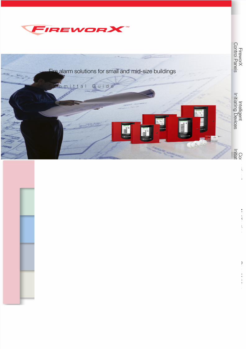
Fire alarm solutions for small and mid-size buildings
S u b m i t t a l G u i d e

8/10/2019 FX85005-0132 -- FireworX Submittal Guide
http://slidepdf.com/reader/full/fx85005-0132-fireworx-submittal-guide 2/56

8/10/2019 FX85005-0132 -- FireworX Submittal Guide
http://slidepdf.com/reader/full/fx85005-0132-fireworx-submittal-guide 3/56
Edwards offers total solutions that protect people and property with some of
the most innovative fire alarm technology ever developed. From integrated life
safety systems to intuitive programming and configuration, all of our products
undergo rigorous scrutiny throughout their development to make sure theylive up to the highest expectations of you, our customer. We invest this
extra-effort with one simple goal in mind, to earn the right for our life safety
solutions to be selected to maintain safe environments in some of the world’s
most important buildings – including yours.
When you invest in FireworX brand fire alarm products, you invest in a legacy
that spans 140 years of innovation, and a team of dedicated people focused
squarely on the future. We’re already at the forefront of emerging newtechnologies. And we’re investing heavily in fire alarm solutions that will make
your world safer.
FX Series
Submittal Guide:
Life Safety Systems

8/10/2019 FX85005-0132 -- FireworX Submittal Guide
http://slidepdf.com/reader/full/fx85005-0132-fireworx-submittal-guide 4/56
8/10/2019 FX85005-0132 -- FireworX Submittal Guide
http://slidepdf.com/reader/full/fx85005-0132-fireworx-submittal-guide 5/56vii
FX Series
Submittal Guide:
Life Safety Systems
Fire alarm solutions
for small to mid-sized
buildings.
8/10/2019 FX85005-0132 -- FireworX Submittal Guide
http://slidepdf.com/reader/full/fx85005-0132-fireworx-submittal-guide 6/56
FireworX Submittal Guide
Fire alarm solutions for small buildings
FireworX is an EDWARDS brand.
8985 Town Center Parkway, Bradenton, FL 34202
© 2013 UTC Fire & Security Americas Corporation, Inc. All rights reserved. Specifications subject to change without
notice. EDWARDS is part of UTC Climate, Controls & Security, a unit of United Technologies Corporation.
8985 Town Center Parkway, Bradenton, FL 34202
FX85005-0132, Issue 3
Wiring diagrams provided herein are for information and reference only and are not to be used for installation
purposes. Consult the appropriate installation documents for wiring and configuration details.
This guidebook is for information only and is not intended as a substitute for verbatim legislated requirements. For
authoritative specifications regarding the application of life safety, security, and access control systems, consult
current editions of applicable codes and standards. For authoritative interpretation of those codes and standards,
consult your local authority having jurisdiction.
While every effort has been made to ensure the accuracy and completeness of this guidebook, the authors and
publishers assume no responsibility for errors, inaccuracies, omissions, or any inconsistencies herein.
FireworX, and Genesis Series are trademarks of UTC Climate Controls and Security.
8/10/2019 FX85005-0132 -- FireworX Submittal Guide
http://slidepdf.com/reader/full/fx85005-0132-fireworx-submittal-guide 7/56
Intelligent Initiating Devices 13
FX Series Detectors ........................................................ 14
FX Series Detector Bases ............................................... 15
SuperDuct Duct Smoke Detectors .................................16
Manual Pull Stations .......................................................17
Input/Output Modules .................................................... 18
Related Equipment .........................................................20
Conventional Initiating Devices 21
500 Series Heat Detectors ............................................. 21
700 Series Heat Detectors ............................................. 22
Heat Detectors ...............................................................24
SuperDuct Smoke Detectors ..........................................26
Beam Smoke Detectors .................................................27
Carbon Monoxide Detector ............................................ 28
Fire Alarm Stations .........................................................29
Explosionproof Stations .................................................. 30
Notification Appliances 31
Wall Strobes, Horns and Chimes ....................................32
Ceiling Horns and Strobes ..............................................33
Wall Speakers and Speaker-strobes ...............................34
Ceiling Speakers and Speaker-strobes ...........................35
Outdoor Speakers and Speaker-Strobes ........................36
Outdoor Strobes and Horn-strobes ................................ 37 Audio Notification System...............................................38
Door Holders & Relays 40
Door Holders ..................................................................40
Relays ............................................................................ 41
FireworX Control Panels & Accessories 1
Specifications ..................................................................2
Intelligent Addressable Control Panels ..............................3
Option Cards for Intelligent Panels ....................................4
Remote Annunciators for Intelligent Panels .......................6
Conventional Control Panels .............................................8
Power Supplies .............................................................. 10
Control Panel Accessories .............................................. 12
ix
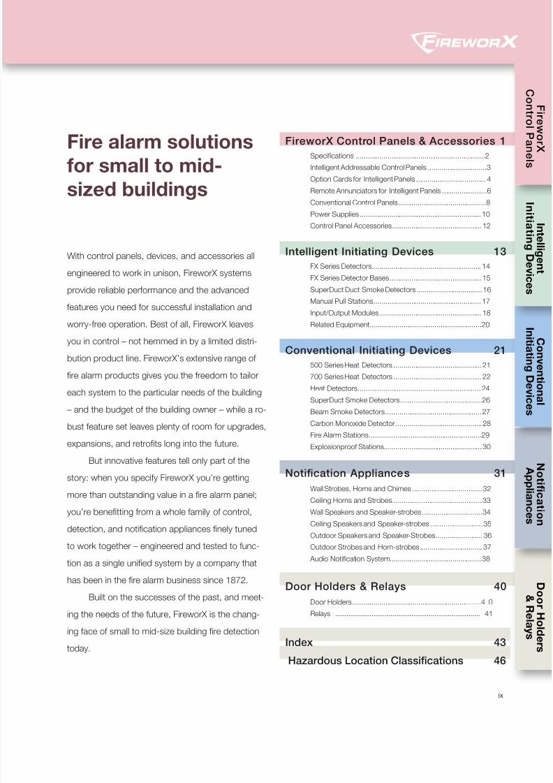
With control panels, devices, and accessories all
engineered to work in unison, FireworX systems
provide reliable performance and the advanced
features you need for successful installation and
worry-free operation. Best of all, FireworX leaves
you in control – not hemmed in by a limited distri-
bution product line. FireworX’s extensive range of
fire alarm products gives you the freedom to tailor
each system to the particular needs of the building
– and the budget of the building owner – while a ro-
bust feature set leaves plenty of room for upgrades,
expansions, and retrofits long into the future.
But innovative features tell only part of the
story: when you specify FireworX you’re getting
more than outstanding value in a fire alarm panel;
you’re benefitting from a whole family of control,
detection, and notification appliances finely tuned
to work together – engineered and tested to func-
tion as a single unified system by a company that
has been in the fire alarm business since 1872.
Built on the successes of the past, and meet-
ing the needs of the future, FireworX is the chang-
ing face of small to mid-size building fire detection
today.
Fire alarm solutionsfor small to mid-
sized buildings
Index 43
Hazardous Location Classifications 46

8/10/2019 FX85005-0132 -- FireworX Submittal Guide
http://slidepdf.com/reader/full/fx85005-0132-fireworx-submittal-guide 8/56
8/10/2019 FX85005-0132 -- FireworX Submittal Guide
http://slidepdf.com/reader/full/fx85005-0132-fireworx-submittal-guide 9/561
Fire Control Panels
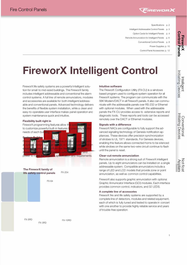
FireworX life safety systems are a powerful intelligent solu-
tion for small to mid-sized buildings. The FireworX family
includes intelligent addressable and conventional fire alarm
control systems. A full line of remote annunciators, modules
and accessories are available for both intelligent/address-
able and conventional panels. Advanced technology delivers
the benefits of flexible system installation, while a clean and
easy-to-operatate user interface makes panel operation and
system maintenance quick and intuitive.
Flexibility built right in
FireworX programming features allow the system designer
to customize powerful built-in features to precisely suit the
needs of each building.
System Builder
FireworX is the only non-proprietary fire alarm product with
a system design tool that virtually eliminates system design
errors. The program prompts the designer for possible
missed components and verifies sufficient capacity and
power to meet the project’s specification and requirements.
Intuitive software
The FireworX Configuration Utility (FX-CU) is a windows
based program used to configure system operation for all
FireworX systems. The program can communicate with the
56K Modem/DACT in all FireworX panels. It also can commu-
nicate with the addressable panels over RS-232 or Ethernet
with optional modules. When used with the addressable
panels the FX-CU provides access to extensive reports and
diagnostic tools. These reports and tools can be accessed
remotely over the DACT or Ethernet modules.
Signals with a difference
FireworX NACs are configurable to fully support the ad-
vanced signaling technology of Genesis notification ap-
pliances. These devices offer precision synchronization
of strobes to UL 1971 standards. For Genesis devices,enabling this feature allows connected horns to be si lenced
while strobes on the same two-wire circuit continue to flash
until the panel is reset.
Clear-cut remote annunciation
Remote annunciation is a strong suit of FireworX intelligent
panels. Up to eight annunciators can be installed on a single
addressable system. Compatible annunciators include a
range of LED and LCD models that provide zone or point
annunciation, as well as common control capabilities.
FireworX also supports graphic annunciation with optional
Graphic Annunicator Interface (GCI) modules. Each interface
provides common control, indicators, and 32 LEDS.
A complete line of accessories
FireworX fire and life safety systems are supported by a
complete line of detectors, modules and related equipment,
each of which is fully tuned and tested to operate in concert
with one another to provide highly reliable service and years
of trouble-free operation.
FireworX Intelligent Control
Specifications p. 2
Intelligent Addressable Control Panels p. 3
Option Cards for Intelligent Panels p. 4
Remote Annunciators for Intelligent Panels p. 6
Conventional Control Panels p. 8
Power Supplies p. 10
Control Panel Accessories p. 12
FX-10RDFX-3RD
FX-254
FX-64
FX-5RD
The FireworX family of
life safety control panels
8/10/2019 FX85005-0132 -- FireworX Submittal Guide
http://slidepdf.com/reader/full/fx85005-0132-fireworx-submittal-guide 10/56
C o n t r o l P a n e l s
SUBMIT
2
Fire Control Panels
U p t o 2 0 , 0
0 0 f e e t o f w i r i n g p e r d a t a l o o p
2
Ethernet
DACT/Dialer
RS-232
Relays: Two Form C, one Form A
Auxiliary Power, programmagle
Auxiliary Power, resettable or continuous
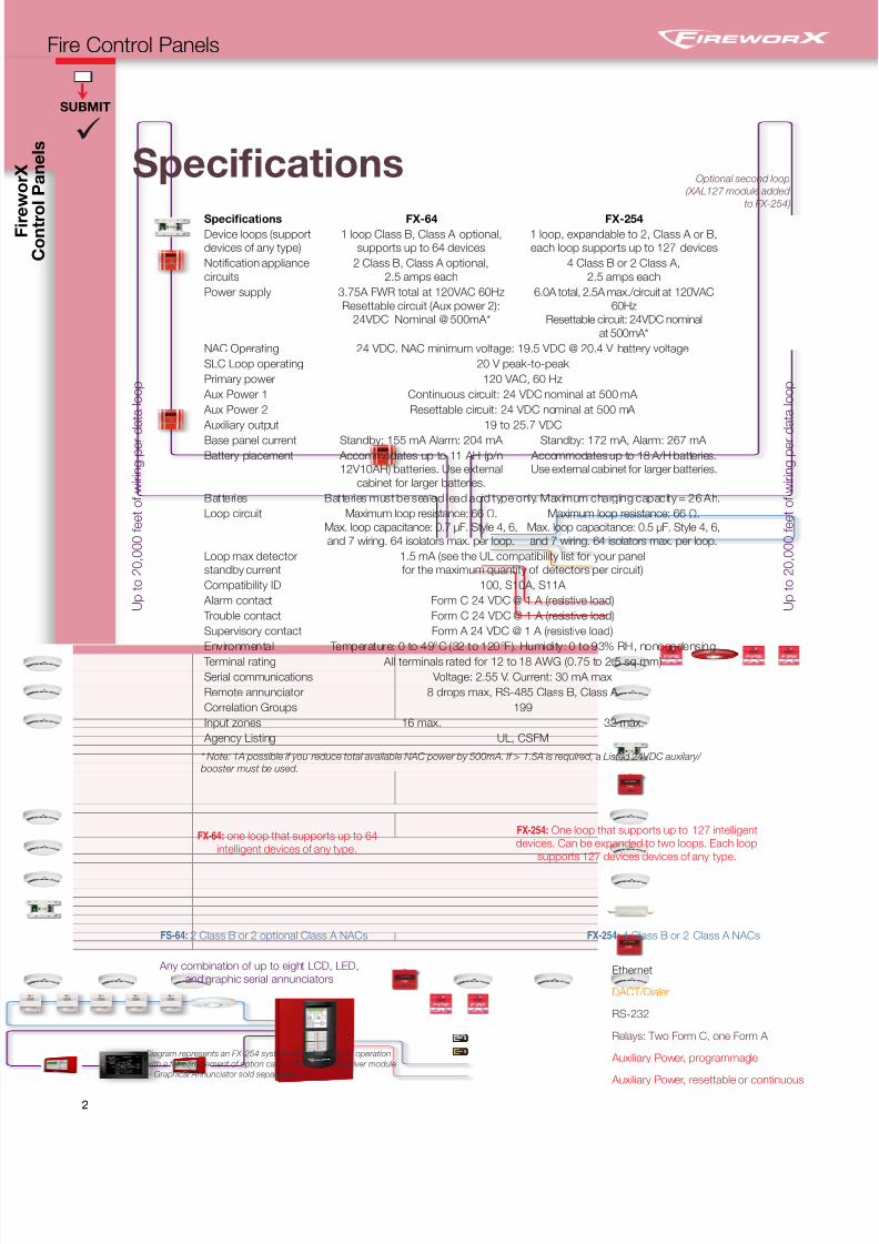
FS-64: 2 Class B or 2 optional Class A NACs
FX-254: One loop that supports up to 127 intelligent
devices. Can be expanded to two loops. Each loop
supports 127 devices devices of any type.
Diagram represents an FX-254 system wired for Class A operation
with a full complement of option cards. (Available GCI driver module
-- Graphical Annunciator sold separately)
Any combination of up to eight LCD, LED,
and graphic serial annunciators
FX-254: 4 Class B or 2 Class A NACs
Specifications FX-64 FX-254Device loops (support
devices of any type)
1 loop Class B, Class A optional,
supports up to 64 devices
1 loop, expandable to 2, Class A or B,
each loop supports up to 127 devices
Notification appliance
circuits
2 Class B, Class A optional,
2.5 amps each
4 Class B or 2 Class A,
2.5 amps each
Power supply 3.75A FWR total at 120VAC 60Hz
Resettable circuit (Aux power 2):
24VDC Nominal @ 500mA*
6.0A total, 2.5A max./circuit at 120VAC
60Hz
Resettable circuit: 24VDC nominal
at 500mA*
NAC Operating 24 VDC. NAC minimum voltage: 19.5 VDC @ 20.4 V battery voltage
SLC Loop operating 20 V peak-to-peak
Primary power 120 VAC, 60 Hz
Aux Power 1 Continuous circuit: 24 VDC nominal at 500 mA
Aux Power 2 Resettable circuit: 24 VDC nominal at 500 mA
Auxiliary output 19 to 25.7 VDC
Base panel current Standby: 155 mA Alarm: 204 mA Standby: 172 mA, Alarm: 267 mA
Battery placement Accommodates up to 11 AH (p/n
12V10AH) batteries. Use external
cabinet for larger batteries.
Accommodates up to 18 A/H batteries.
Use external cabinet for larger batteries.
Batteries Batteries must be sealed lead acid type only. Maximum charging capacity = 26 Ah.
Loop circuit Maximum loop resistance: 66 Ω.
Max. loop capacitance: 0.7 µF. Style 4, 6,
and 7 wiring. 64 isolators max. per loop.
Maximum loop resistance: 66 Ω.
Max. loop capacitance: 0.5 µF. Style 4, 6,
and 7 wiring. 64 isolators max. per loop.
Loop max detector
standby current
1.5 mA (see the UL compatibility list for your panel
for the maximum quantity of detectors per circuit)
Compatibility ID 100, S10A, S11A
Alarm contact Form C 24 VDC @ 1 A (resistive load)
Trouble contact Form C 24 VDC @ 1 A (resistive load)
Supervisory contact Form A 24 VDC @ 1 A (resistive load)
Environmental Temperature: 0 to 49°C (32 to 120°F). Humidity: 0 to 93% RH, noncondensing
Terminal rating All terminals rated for 12 to 18 AWG (0.75 to 2.5 sq mm)
Serial communications Voltage: 2.55 V. Current: 30 mA max
Remote annunciator 8 drops max, RS-485 Class B, Class A
Correlation Groups 199
Input zones 16 max. 32 max.
Agency Listing UL, CSFM
Optional second loop
(XAL127 module added
to FX-254)
Specifications
U p t o 2 0 , 0
0 0 f e e t o f w i r i n g p e r d a t a l o o p
FX-64: one loop that supports up to 64
intelligent devices of any type.
* Note: 1A possible if you reduce total available NAC power by 500mA. If > 1.5A is required, a Listed 24VDC auxilary/
booster must be used.
8/10/2019 FX85005-0132 -- FireworX Submittal Guide
http://slidepdf.com/reader/full/fx85005-0132-fireworx-submittal-guide 11/56
SUBMIT
3
Fire Control Panels
SUBMIT
3
Intelligent
AddressableControl Panels
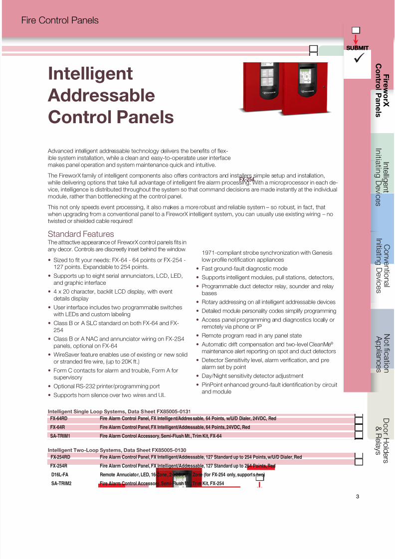
Intelligent Single Loop Systems, Data Sheet FX85005-0131
FX-64RD Fire Alarm Control Panel, FX Intelligent/Addressable, 64 Points, w/U/D Dialer, 24VDC, Red
FX-64R Fire Alarm Control Panel, FX Intelligent/Addressable, 64 Points, 24VDC, Red
SA-TRIM1 Fire Alarm Control Accessory, Semi-Flush Mt., Trim Kit, FX-64
Intelligent Two-Loop Systems, Data Sheet FX85005-0130
FX-254RD Fire Alarm Control Panel, FX Intelligent/Addressable, 127 Standard up to 254 Points, w/U/D Dialer, Red
FX-254R Fire Alarm Control Panel, FX Intelligent/Addressable, 127 Standard up to 254 Points, Red
D16L-FA Remote Annuciator, LED, 16-Zone, 2-LEDs per Zone (for FX-254 only, supports two)
SA-TRIM2 Fire Alarm Control Accessory, Semi-Flush Mt., Trim Kit, FX-254
Advanced intelligent addressable technology delivers the benefits of flex-
ible system installation, while a clean and easy-to-operatate user interface
makes panel operation and system maintenance quick and intuitive.
The FireworX family of intelligent components also offers contractors and installers simple setup and installation,
while delivering options that take full advantage of intelligent fire alarm processing. With a microprocessor in each de-
vice, intelligence is distributed throughout the system so that command decisions are made instantly at the individual
module, rather than bottlenecking at the control panel.
This not only speeds event processing, it also makes a more robust and reliable system – so robust, in fact, that
when upgrading from a conventional panel to a FireworX intelligent system, you can usually use existing wiring – no
twisted or shielded cable required!
Standard Features The attractive appearance of FireworX control panels fits in
any decor. Controls are discreetly inset behind the window.
• Sized to fit your needs: FX-64 - 64 points or FX-254 -
127 points. Expandable to 254 points.
• Supports up to eight serial annunciators, LCD, LED,
and graphic interface
• 4 x 20 character, backlit LCD display, with eventdetails display
• User interface includes two programmable switches
with LEDs and custom labeling
• Class B or A SLC standard on both FX-64 and FX-
254
• Class B or A NAC and annunciator wiring on FX-2S4
panels, optional on FX-64
• WireSaver feature enables use of existing or new solid
or stranded fire wire, (up to 20K ft.)
• Form C contacts for alarm and trouble, Form A for
supervisory
• Optional RS-232 printer/programming port
• Supports horn silence over two wires and UL
FX-64
FX-254
1971-compliant strobe synchronization with Genesis
low profile notification appliances
• Fast ground-fault diagnostic mode
• Supports intelligent modules, pull stations, detectors,
• Programmable duct detector relay, sounder and relay
bases• Rotary addressing on all intelligent addressable devices
• Detailed module personality codes simplify programming
• Access panel programming and diagnostics locally or
remotely via phone or IP
• Remote program read in any panel state
• Automatic drift compensation and two-level CleanMe®
maintenance alert reporting on spot and duct detectors
• Detector Sensitivity level, alarm verification, and pre
alarm set by point
• Day/Night sensitivity detector adjustment
• PinPoint enhanced ground-fault identification by circuit
and module
8/10/2019 FX85005-0132 -- FireworX Submittal Guide
http://slidepdf.com/reader/full/fx85005-0132-fireworx-submittal-guide 12/56
C o n t r o l P a n e l s
SUBMIT
4
Fire Control Panels
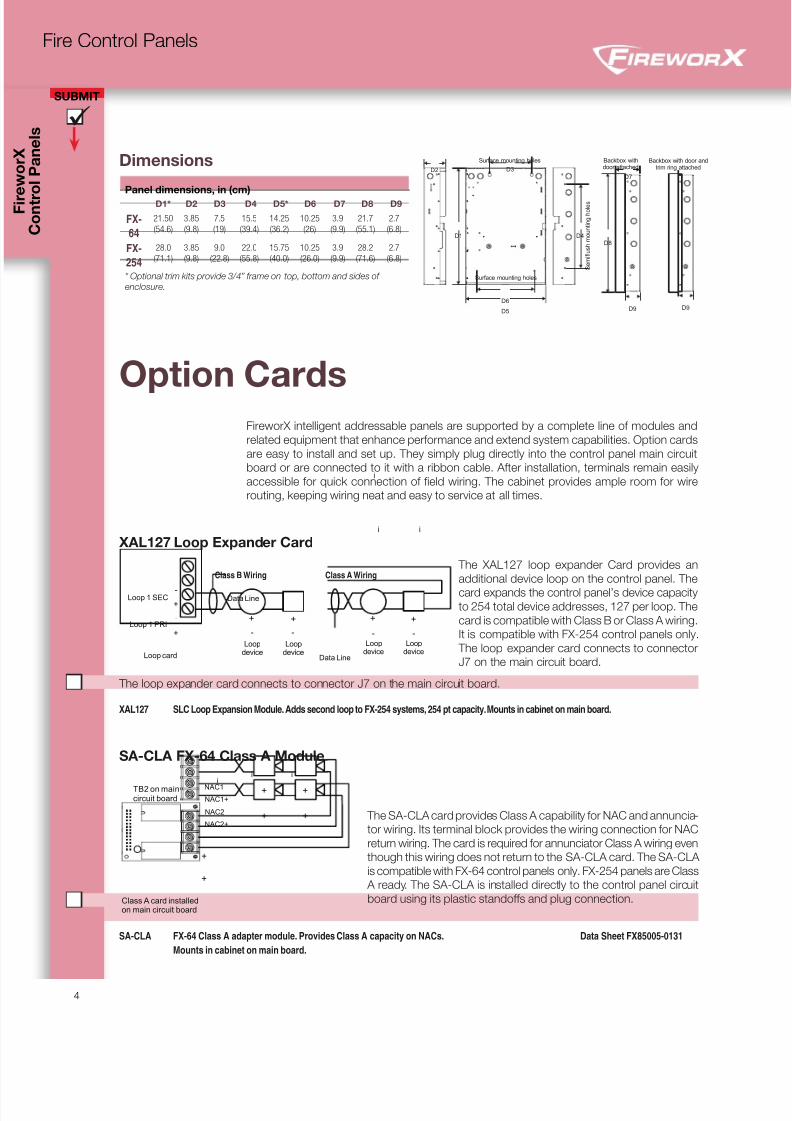
Option CardsFireworX intelligent addressable panels are supported by a complete line of modules and
related equipment that enhance performance and extend system capabilities. Option cards
are easy to install and set up. They simply plug directly into the control panel main circuit
board or are connected to it with a ribbon cable. After installation, terminals remain easily
accessible for quick connection of field wiring. The cabinet provides ample room for wire
routing, keeping wiring neat and easy to service at all times.
XAL127 Loop Expander Card
The XAL127 loop expander Card provides an
additional device loop on the control panel. The
card expands the control panel’s device capacityto 254 total device addresses, 127 per loop. The
card is compatible with Class B or Class A wiring.
It is compatible with FX-254 control panels only.
The loop expander card connects to connector
J7 on the main circuit board.
The loop expander card connects to connector J7 on the main circuit board.
XAL127 SLC Loop Expansion Module. Adds second loop to FX-254 systems, 254 pt capacity. Mounts in cabinet on main board.
SA-CLA FX-64 Class A Module
The SA-CLA card provides Class A capability for NAC and annuncia-
tor wiring. Its terminal block provides the wiring connection for NAC
return wiring. The card is required for annunciator Class A wiring even
though this wiring does not return to the SA-CLA card. The SA-CLA
is compatible with FX-64 control panels only. FX-254 panels are Class
A ready. The SA-CLA is installed directly to the control panel circuit
board using its plastic standoffs and plug connection.
SA-CLA FX-64 Class A adapter module. Provides Class A capacity on NACs. Data Sheet FX85005-0131
Mounts in cabinet on main board.
Dimensions
Panel dimensions, in (cm)
D1* D2 D3 D4 D5* D6 D7 D8 D9
FX-
64
21.50
(54.6)
3.85
(9.8)
7.5
(19)
15.5
(39.4)
14.25
(36.2)
10.25
(26)
3.9
(9.9)
21.7
(55.1)
2.7
(6.8)
FX-
254
28.0
(71.1)
3.85
(9.8)
9.0
(22.8)
22.0
(55.8)
15.75
(40.0)
10.25
(26.0)
3.9
(9.9)
28.2
(71.6)
2.7
(6.8)
* Optional trim kits provide 3/4” frame on top, bottom and sides ofenclosure.
D1
D2 D3
D4
D5
D6
Surface mounting holes
S e m i f l u s h m o u n t i n g h o l e s
Surface mounting holes
D8
D7
D9
Backbox withdoor attached
Backbox with door andtrim ring attached
D9
Loop 1 SEC
Loop card
+
Loop 1 PRI+
+ +
Loopdevice
Loopdevice
Data Line
i ii
-
-
- -
i i
i
+ +
Loopdevice
Loopdevice
Data Line
- -
Class B Wiring Class A Wiring
Class A card installed
on main circuit board
NAC1
NAC2+
NAC2
NAC1+
+ +
+ +
+
+
TB2 on main
circuit board
8/10/2019 FX85005-0132 -- FireworX Submittal Guide
http://slidepdf.com/reader/full/fx85005-0132-fireworx-submittal-guide 13/56
SUBMIT
5
Fire Control Panels
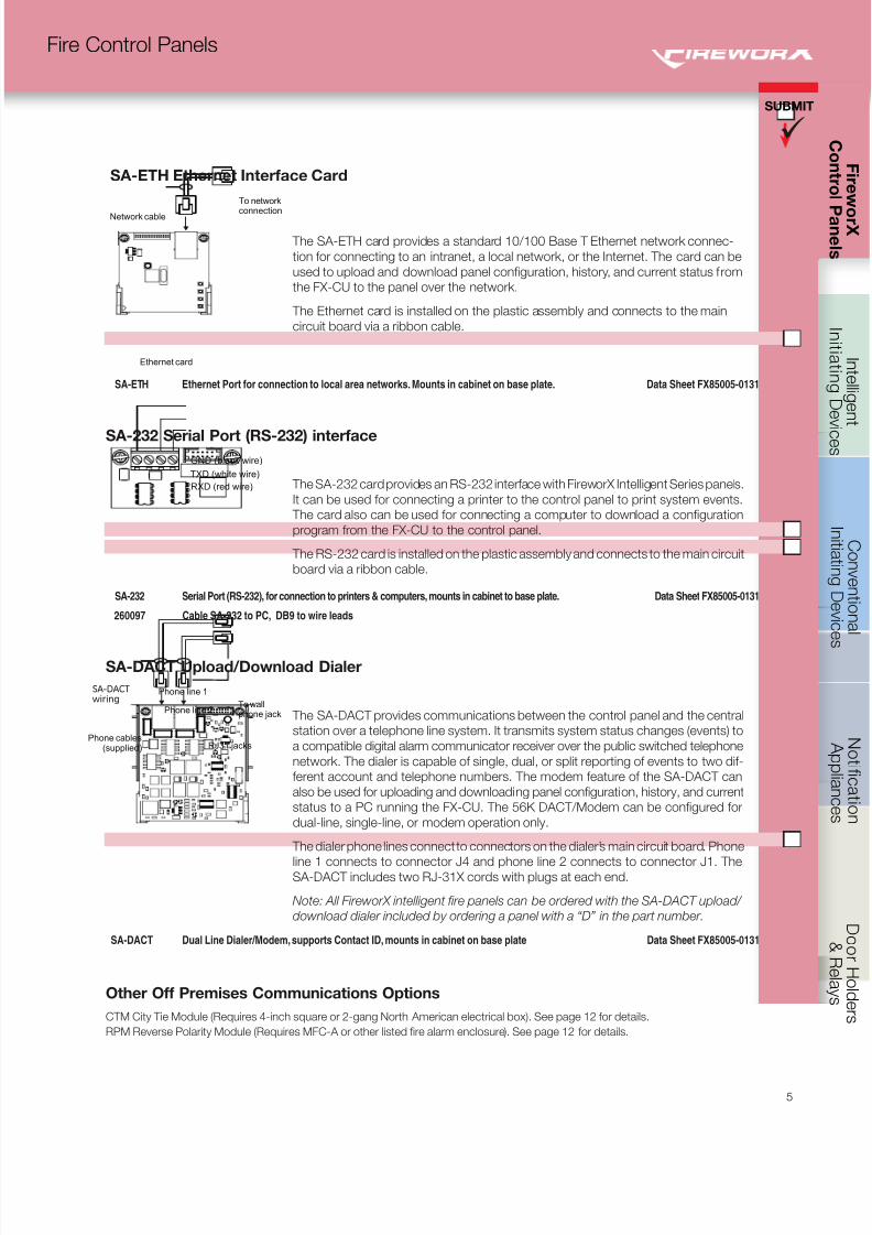
SA-ETH Ethernet Interface Card
The SA-ETH card provides a standard 10/100 Base T Ethernet network connec-
tion for connecting to an intranet, a local network, or the Internet. The card can be
used to upload and download panel configuration, history, and current status from
the FX-CU to the panel over the network.
The Ethernet card is installed on the plastic assembly and connects to the main
circuit board via a ribbon cable.
SA-ETH Ethernet Port for connection to local area networks. Mounts in cabinet on base plate. Data Sheet FX85005-0131
SA-232 Serial Port (RS-232) interface
The SA-232 card provides an RS-232 interface with FireworX Intelligent Series panels.
It can be used for connecting a printer to the control panel to print system events.
The card also can be used for connecting a computer to download a configuration
program from the FX-CU to the control panel.
The RS-232 card is installed on the plastic assembly and connects to the main circuit
board via a ribbon cable.
SA-232 Serial Port (RS-232), for connection to printers & computers, mounts in cabinet to base plate. Data Sheet FX85005-0131 260097 Cable SA-232 to PC, DB9 to wire leads
SA-DACT Upload/Download Dialer
The SA-DACT provides communications between the control panel and the central
station over a telephone line system. It transmits system status changes (events) to
a compatible digital alarm communicator receiver over the public switched telephone
network. The dialer is capable of single, dual, or split reporting of events to two dif-
ferent account and telephone numbers. The modem feature of the SA-DACT can
also be used for uploading and downloading panel configuration, history, and current
status to a PC running the FX-CU. The 56K DACT/Modem can be configured for
dual-line, single-line, or modem operation only.
The dialer phone lines connect to connectors on the dialer’s main circuit board. Phone
line 1 connects to connector J4 and phone line 2 connects to connector J1. TheSA-DACT includes two RJ-31X cords with plugs at each end.
Note: All FireworX intelligent fire panels can be ordered with the SA-DACT upload/
download dialer included by ordering a panel with a “D” in the part number.
SA-DACT Dual Line Dialer/Modem, supports Contact ID, mounts in cabinet on base plate Data Sheet FX85005-0131
Network cable
Ethernet card
To network
connection
GND (black wire)
TXD (white wire)
RXD (red wire)
Phone line 1
Phone line 2 To wall
phone jack
Phone cables(supplied) RJ31 jacks
SA-DACTwiring
Other Off Premises Communications Options
CTM City Tie Module (Requires 4-inch square or 2-gang North American electrical box). See page 12 for details.
RPM Reverse Polarity Module (Requires MFC-A or other listed fire alarm enclosure). See page 12 for details.
8/10/2019 FX85005-0132 -- FireworX Submittal Guide
http://slidepdf.com/reader/full/fx85005-0132-fireworx-submittal-guide 14/56
C o n t r o l P a n e l s
SUBMIT
6
Fire Control Panels
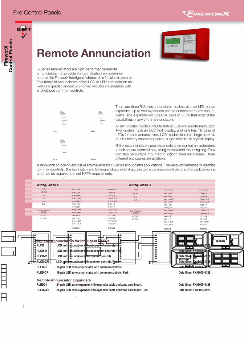
Remote Annunciation
R-Series Annunciators are high-performance remote
annunciators that provide status indication and common
controls for FireworX Intelligent Addressable fire alarm systems.
This family of annunciators offers LCD or LED annunciation as
well as a graphic annunciator driver. Models are available with
and without common controls.
Controls Enabled
Ack/Silence
Reset
Signal Silence
Drill
Lamp Test
Power FireAlarmSupervisoryGround FaultTrouble
RLCD-C
Controls Enabled
Ack/Silence
Lamp Test
Power FireAlarmSupervisoryGround FaultTrouble
RLCD
l l
il
i l il
ill
i li
ll
l l
il
i l il
ill
i li
ll
l l
il
i li
ll
Controls Enabled
Ack/Silence
Reset
Signal Silence
Drill
Lamp Test
Power FireAlarmSupervisoryGround FaultTrouble
RLED-C
RLED24
There are three R-Series annunciator models, plus an LED-based
expander. Up to two expanders can be connected to any annun-
ciator. The expander includes 24 pairs of LEDs that extend the
capabilities of any of the annunciators. All annunciator models include status LEDs and an internal buzzer.
Two models have an LCD text display, and one has 16 pairs of
LEDs for zone annunciation. LCD models feature a large back-lit,
four by twenty character per line, super-twist liquid crystal display.
R-Series annunciators and expanders are mounted on a standard
4-inch square electrical box, using the included mounting ring. They
can also be surface mounted in locking steel enclosures. Three
different enclosures are available.
A keyswitch or locking enclosure are available for R-Series annunciator applications. The keyswitch enables or disables
common controls. The key switch and locking enclosures limit access to the common controls to authorized personnel
and may be required to meet NFPA requirements.
Annunciator
CH2 (–) OUT
CH2 (+) OUT
CH2 ( ) IN –
CH2 (+) IN
CH1 ( ) OUT –
CH1 (+) OUT
CH1 ( ) IN –
CH1 (+) IN
24V (+) IN
24V ( ) IN –
GROUND
24V (+) OUT
24V ( ) OUT –
24 VDC +
LISTED 24 VDCSUPPLY
24 VDC –
Annunciator
CH2 (–) OUT
CH2 (+) OUT
CH2 ( ) IN –
CH2 (+) IN
CH1 ( ) OUT –
CH1 (+) OUT
CH1 ( ) IN –
CH1 (+) IN
24V (+) IN
24V ( ) IN –
GROUND
24V (+) OUT
24V ( ) OUT –
CH2 –
CH2 +
CH1 –
CH1 +
FACP
RS-485
I
I
I
I
I
I
I
I
I
I
I
I
I
I I
I
I
I
I
I
I
I
I
I
I
I
I
I
Annunciator
CH2 (–) OUT
CH2 (+) OUT
CH2 ( ) IN –
CH2 (+) IN
CH1 ( ) OUT –
CH1 (+) OUT
CH1 ( ) IN –
CH1 (+) IN
24V (+) IN
24V ( ) IN –
GROUND
24V (+) OUT
24V ( ) OUT –
24 VDC +
LISTED 24 VDCSUPPLY
24 VDC –
FACP Annunciator
CH2 (–) OUT
CH2 (+) OUT
CH2 ( ) IN –
CH2 (+) IN
CH1 ( ) OUT –
CH1 (+) OUT
CH1 ( ) IN –
CH1 (+) IN
24V (+) IN
24V ( ) IN –
GROUND
24V (+) OUT
24V ( ) OUT –
RS-485
CH1 +
CH1 –
I I
Wiring, Class A Wiring, Class B
Remote Annunciators for Intelligent Panels RLCD LCD text annunciator without common controls. Data Sheet FX85005-0128
RLCD-R LCD text annunciator without common controls. Red. Data Sheet FX85005-0128
RLCD-C LCD text annunciator with common controls. Data Sheet FX85005-0128
RLCD-CR LCD text annunciator with common controls. Red. Data Sheet FX85005-0128
RLED-C 16-pair LED zone annunciator with common controls. Data Sheet FX85005-0128
RLED-CR 16-pair LED zone annunciator with common controls. Red. Data Sheet FX85005-0128
Remote Annunciator Expanders
RLED24 24-pair LED zone expander with expander cable and zone card insert. Data Sheet FX85005-0128
RLED24R 24-pair LED zone expander with expander cable and zone card insert. Red. Data Sheet FX85005-0128
8/10/2019 FX85005-0132 -- FireworX Submittal Guide
http://slidepdf.com/reader/full/fx85005-0132-fireworx-submittal-guide 15/56
SUBMIT
7
Fire Control Panels
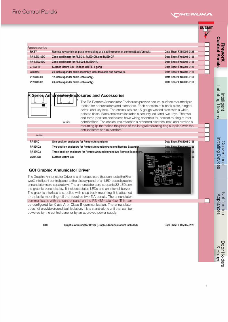
R Series Annunciator Enclosures and Accessories
RA-ENC2
The RA Remote Annunciator Enclosures provide secure, surface mounted pro-
tection for annunciators and extenders. Each consists of a back plate, hinged
cover, and key lock. The enclosures are 16-gauge welded steel with a white,
painted finish. Each enclosure includes a security lock and two keys. The two-and three-position enclosures have wiring channels for correct routing of inter-
connections. The enclosures attach to a standard electrical box, and provide a
mounting lip that takes the place of the integral mounting ring supplied with the
annunciators and expanders.
RA-ENC1 One-position enclosure for Remote Annunciator. Data Sheet FX85005-0128
RA-ENC2 Two-position enclosure for Remote Annunciator and one Remote Expander. Data Sheet FX85005-0128
RA-ENC3 Three-position enclosure for Remote Annunciator and two Remote Expanders. Data Sheet FX85005-0128
LSRA-SB Surface Mount Box Data Sheet FX85005-0128
GCI Graphic Annunicator Driver
The Graphic Annunciator Driver is an interface card that connects the Fire-
worX Intelligent control panel to the display panel of an LED-based graphic
annunciator (sold separately). The annunciator card supports 32 LEDs on
the graphic panel display. It includes status LEDs and an internal buzzer.
The graphic interface is supplied with snap track mounting. It is attached
to a plastic mounting rail that requires two EIA panels. The annunciator
communicates with the control panel on the RS-485 data riser. This can
be configured for Class A or Class B communication. The annunciator
does not provide ground fault isolation. It is a stand-alone unit that can be
powered by the control panel or by an approved power supply.
GCI Graphic Annunciator Driver (Graphic Annunciator not included) Data Sheet FX85005-0128
Accessories
RKEY Remote key switch on plate for enabling or disabling common controls (Lock/Unlock). Data Sheet FX85005-0128
RA-LED16ZC Zone card insert for RLED-C, RLED-CR, and RLED-CF. Data Sheet FX85008-0128
RA-LED24ZC Zone card insert for RLED24, RLED24R. Data Sheet FX85008-0128
27193-16 Surface Mount Box - Indoor, WHITE, 1-gang Data Sheet FX85008-0128
7300073 24-inch expander cable assembly, includes cable and hardware. Data Sheet FX85008-0128
7120313-01 12-inch expander cable (cable only). Data Sheet FX85008-0128
7120313-02 24-inch expander cable (cable only). Data Sheet FX85008-0128
RA-ENC1
8/10/2019 FX85005-0132 -- FireworX Submittal Guide
http://slidepdf.com/reader/full/fx85005-0132-fireworx-submittal-guide 16/56
C o n t r o l P a n e l s
SUBMIT
8
Fire Control Panels
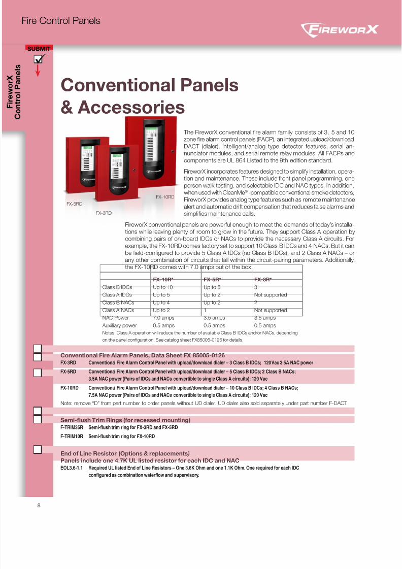
Conventional Panels
& Accessories The FireworX conventional fire alarm family consists of 3, 5 and 10
zone fire alarm control panels (FACP), an integrated upload/download
DACT (dialer), intelligent/analog type detector features, serial an-
nunciator modules, and serial remote relay modules. All FACPs and
components are UL 864 Listed to the 9th edition standard.
FireworX incorporates features designed to simplify installation, opera-
tion and maintenance. These include front panel programming, one
person walk testing, and selectable IDC and NAC types. In addition,
when used with CleanMe® -compatible conventional smoke detectors,
FireworX provides analog type features such as remote maintenancealert and automatic drift compensation that reduces false alarms and
simplifies maintenance calls.
FireworX conventional panels are powerful enough to meet the demands of today’s installa-
tions while leaving plenty of room to grow in the future. They support Class A operation by
combining pairs of on-board IDCs or NACs to provide the necessary Class A circuits. For
example, the FX-10RD comes factory set to support 10 Class B IDCs and 4 NACs. But it can
be field-configured to provide 5 Class A IDCs (no Class B IDCs), and 2 Class A NACs – or
any other combination of circuits that fall within the circuit-pairing parameters. Additionally,
the FX-10RD comes with 7.0 amps out of the box.
FX-10R* FX-5R* FX-3R*
Class B IDCs Up to 10 Up to 5 3
Class A IDCs Up to 5 Up to 2 Not supported
Class B NACs Up to 4 Up to 2 2
Class A NACs Up to 2 1 Not supported
NAC Power 7.0 amps 3.5 amps 3.5 amps
Auxiliary power 0.5 amps 0.5 amps 0.5 amps
Notes: Class A operation will reduce the number of available Class B IDCs and/or NACs, depending
on the panel configuration. See catalog sheet FX85005-0126 for details.
Conventional Fire Alarm Panels, Data Sheet FX 85005-0126
FX-3RD Conventional Fire Alarm Control Panel with upload/download dialer – 3 Class B IDCs; 120 Vac 3.5A NAC power
FX-5RD Conventional Fire Alarm Control Panel with upload/download dialer – 5 Class B IDCs; 2 Class B NACs;
3.5A NAC power (Pairs of IDCs and NACs convertible to single Class A circuits); 120 Vac
FX-10RD Conventional Fire Alarm Control Panel with upload/download dialer – 10 Class B IDCs; 4 Class B NACs;
7.5A NAC power (Pairs of IDCs and NACs convertible to single Class A circuits); 120 Vac
Note: remove “D” from part number to order panels without UD dialer. UD dialer also sold separately under part number F-DACT
Semi-flush Trim Rings (for recessed mounting)
F-TRIM35R Semi-flush trim ring for FX-3RD and FX-5RD
F-TRIM10R Semi-flush trim ring for FX-10RD
End of Line Resistor (Options & replacements )
Panels include one 4.7K UL listed resistor for each IDC and NAC
EOL3.6-1.1 Required UL listed End of Line Resistors – One 3.6K Ohm and one 1.1K Ohm. One required for each IDC
configured as combination waterflow and supervisory.
FX-5RDFX-10RD
FX-3RD
8/10/2019 FX85005-0132 -- FireworX Submittal Guide
http://slidepdf.com/reader/full/fx85005-0132-fireworx-submittal-guide 17/56
SUBMIT
9
Fire Control Panels
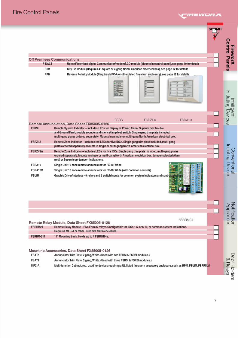
Off Premises Communications F-DACT Upload/download digital Communicator/modem/LCD module (Mounts in control panel), see page 10 for details
CTM City Tie Module (Requires 4” square or 2-gang North American electrical box), see page 12 for details
RPM Reverse Polarity Module (Requires MFC-A or other listed fire alarm enclosure), see page 12 for details
FSRSI FSRZI-A FSRA10
Remote Annunciation, Data Sheet FX85005-0126
FSRSI Remote System Indicator – Includes LEDs for display of Power, Alarm, Supervisory, Trouble
and Ground Fault, trouble sounder and silence/lamp test switch. Single gang trim plate included,
multi-gang plates ordered separately. Mounts in a single or multi-gang North American electrical box.
FSRZI-A Remote Zone Indicator – Includes red LEDs for five IDCs. Single gang trim plate included, multi-gang
plates ordered separately. Mounts in single or multi-gang North American electrical box.
FSRZI-SA Remote Zone Indicator – Includes LEDs for five IDCs. Single gang trim plate included, multi-gang plates
ordered separately. Mounts in single or multi-gang North American electrical box. Jumper selected Alarm
(red) or Supervisory (amber) indications.
FSRA10 Single Unit 10 zone remote annunciator for FX-10, White
FSRA10C Single Unit 10 zone remote annunciator for FX-10, White (with common controls)
FSUIM Graphic Driver/Interface - 9 relays and 5 switch inputs for common system indicators and control functions
FSRRM24Remote Relay Module, Data Sheet FX85005-0126
FSRRM24 Remote Relay Module – Five Form C relays. Configurable for IDCs 1-5, or 6-10, or common system indications.
Requires MFC-A or other listed fire alarm enclosure.
FSRRM-S11 11” Mounting track. Holds up to 4 FSRRM24s.
Mounting Accessories, Data Sheet FX85005-0126
FSAT2 Annunciator Trim Plate, 2 gang, White. (Used with two FSRSI & FSRZI modules.)
FSAT3 Annunciator Trim Plate, 3 gang, White. (Used with three FSRSI & FSRZI modules.)
MFC-A Multi-function Cabinet, red. Used for devices requiring a UL listed fire alarm accessory enclosure, such as RPM, FSUIM, FSRRM24
8/10/2019 FX85005-0132 -- FireworX Submittal Guide
http://slidepdf.com/reader/full/fx85005-0132-fireworx-submittal-guide 18/56
C o n t r o l P a n e l s
SUBMIT
10
Fire Control Panels
Power Supplies
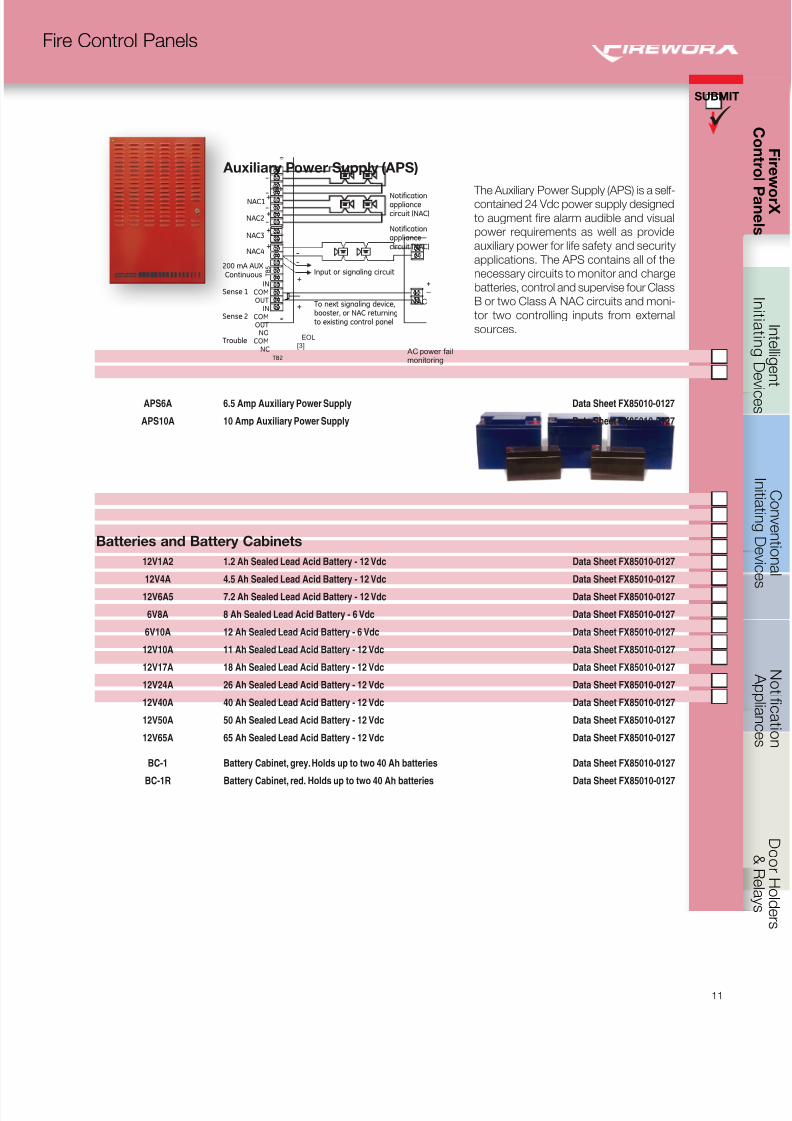
Remote Booster Power Supply The Remote Booster Power Supply is a self-contained 24 Vdc regulated power supply
designed to augment fire alarm audible and visual power requirements as well as provide
power for auxiliary, access control and security applications. The booster contains all of the
necessary circuits to monitor and charge batteries, control and supervise four Class B or
two Class A NAC circuits and monitor two controlling inputs from external sources.
Simple switch selection provides a wide variety of operational configurations. Each remote
booster power supply is supplied with its own enclosure providing ample space for additional
interface modules and battery compartment.
When used with Genesis Notification appliances, the booster provides the ability to syn-
chronize strobes as well as horn signals. The booster flexibility allows synchronization with
upstream devices, or, the booster may be used to synchronize downstream devices, as
well as other boosters and their connected devices. When used with the FX-NAC module
complete building synchronization is possible.
EBPS notification appliance circuits easily configure for either of two signaling rates: temporal 3
or continuous. This makes the EBPS ideal for applications requiring signaling rates not avail-
able from the main panel. It also allows independent setup of a notification appliance circuit
without interfering with the main panel and its initiating circuits. In addition to the generated
signal rates, the EBPS can also be configured to follow the signal rate of the main panel’s
notification appliance circuit. This allows seamless expansion of existing NACs.
EBPS6A 6.5 Amp Booster Power Supply Data Sheet FX85005-0125
EBPS10A 10 Amp Booster Power Supply Data Sheet FX85005-0125
Note: See FireworX intelligent addressable section for more information on the FX-NAC notification appliance circuit module.
Booster Power Supply
Sense NAC
Parallel ConnectionThe number of boosters
that can be connectedtogether is limited by wire
run length and available current
Booster Power Supply
Sense NAC
NACCircuit
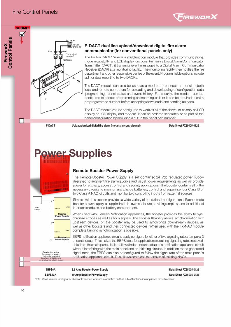
F-DACT dual line upload/download digital fire alarm
communicator (for conventional panels only)
The built-in DACT/Dialer is a multifunction module that provides communications,modem capability, and LCD display functions. Primarily a Digital Alarm Communicator
Transmitter (DACT), it transmits event messages to a Digital Alarm Communicator
Receiver (DACR) at a monitoring facility. The monitoring facility then notifies the fire
department and other responsible parties of the event. Programmable options include
split or dual reporting to two DACRs.
The DACT module can also be used as a modem to connect the panel to both
local and remote computers for uploading and downloading of configuration data
(programming), panel status and event history. For security, the modem can be
configured to accept programming on incoming calls or it can be required to call a
preprogrammed number before accepting downloads and sending uploads.
The DACT module can be configured to work as all of the above, or as only an LCD
display or LCD display and modem. It can be ordered separately or as part of thepanel configuration by including a “D” in the panel part number.
F-DACT Upload/dowload digital fire alarm (mounts in control panel) Data Sheet FX85005-0126
J2
Line 1 Line 2
To wallphone jack
Phone cables(supplied)
RJ31 jacks
RJ31 jacks
8/10/2019 FX85005-0132 -- FireworX Submittal Guide
http://slidepdf.com/reader/full/fx85005-0132-fireworx-submittal-guide 19/56
SUBMIT
11
Fire Control Panels
Batteries and Battery Cabinets
12V1A2 1.2 Ah Sealed Lead Acid Battery - 12 Vdc Data Sheet FX85010-0127 12V4A 4.5 Ah Sealed Lead Acid Battery - 12 Vdc Data Sheet FX85010-0127 12V6A5 7.2 Ah Sealed Lead Acid Battery - 12 Vdc Data Sheet FX85010-0127 6V8A 8 Ah Sealed Lead Acid Battery - 6 Vdc Data Sheet FX85010-0127 6V10A 12 Ah Sealed Lead Acid Battery - 6 Vdc Data Sheet FX85010-0127 12V10A 11 Ah Sealed Lead Acid Battery - 12 Vdc Data Sheet FX85010-0127 12V17A 18 Ah Sealed Lead Acid Battery - 12 Vdc Data Sheet FX85010-0127 12V24A 26 Ah Sealed Lead Acid Battery - 12 Vdc Data Sheet FX85010-0127 12V40A 40 Ah Sealed Lead Acid Battery - 12 Vdc Data Sheet FX85010-0127 12V50A 50 Ah Sealed Lead Acid Battery - 12 Vdc Data Sheet FX85010-0127 12V65A 65 Ah Sealed Lead Acid Battery - 12 Vdc Data Sheet FX85010-0127
BC-1 Battery Cabinet, grey. Holds up to two 40 Ah batteries Data Sheet FX85010-0127
BC-1R Battery Cabinet, red. Holds up to two 40 Ah batteries Data Sheet FX85010-0127
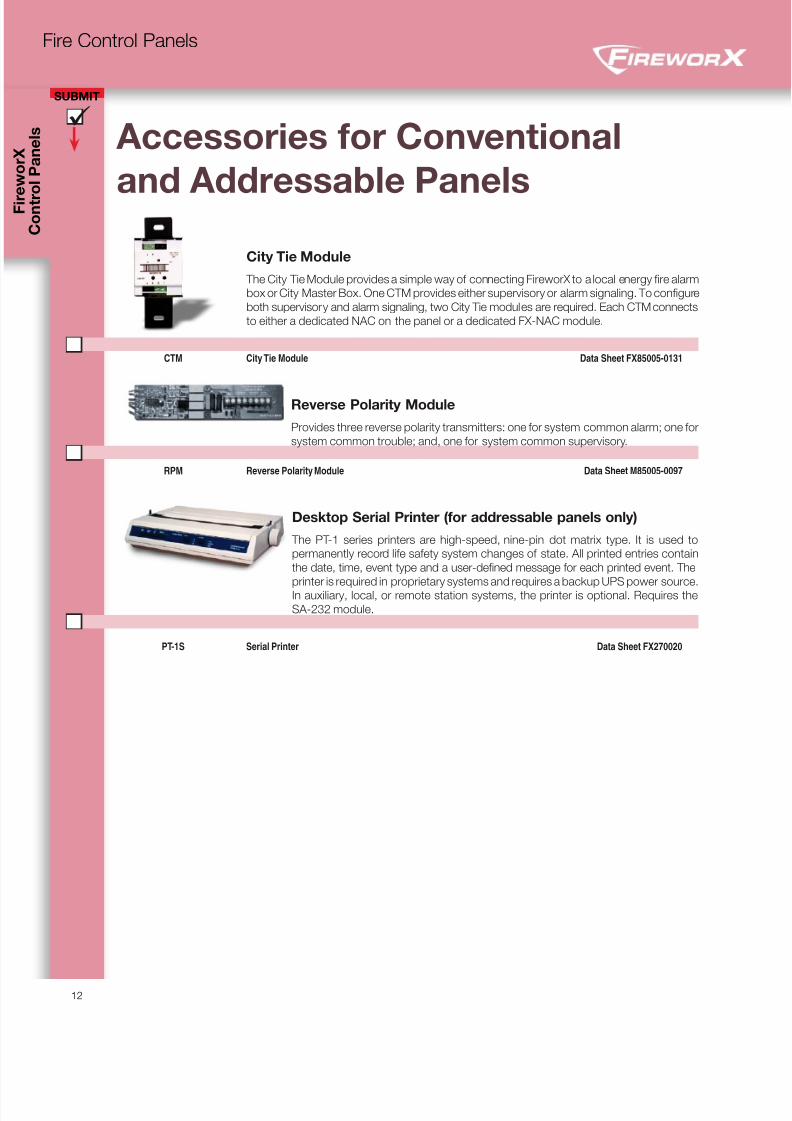
Auxiliary Power Supply (APS)
Notificationappliancecircuit (NAC)
Notificationappliancecircuit (NAC)
To next signaling device,booster, or NAC returningto existing control panel
+
+
OUT
OUT
NC
Sense 1
Sense 2
Trouble
COM
COM
COM
IN
IN
NO
NAC1
NAC2
NAC3
NAC4
+
+
+
+
TB2
TB1
T B 5 200 mA AUX
Continuous Input or signaling circuit
NAC
+
-
AC power failmonitoring
EOL
[3]
The Auxiliary Power Supply (APS) is a self-contained 24 Vdc power supply designed
to augment fire alarm audible and visual
power requirements as well as provide
auxiliary power for life safety and security
applications. The APS contains all of the
necessary circuits to monitor and charge
batteries, control and supervise four Class
B or two Class A NAC circuits and moni-
tor two controlling inputs from external
sources.
APS6A 6.5 Amp Auxiliary Power Supply Data Sheet FX85010-0127 APS10A 10 Amp Auxiliary Power Supply Data Sheet FX85010-0127
8/10/2019 FX85005-0132 -- FireworX Submittal Guide
http://slidepdf.com/reader/full/fx85005-0132-fireworx-submittal-guide 20/56
C o n t r o l P a n e l s
SUBMIT
12
Fire Control Panels
City Tie Module
The City Tie Module provides a simple way of connecting FireworX to a local energy fire alarm
box or City Master Box. One CTM provides either supervisory or alarm signaling. To configure
both supervisory and alarm signaling, two City Tie modules are required. Each CTM connects
to either a dedicated NAC on the panel or a dedicated FX-NAC module.
CTM City Tie Module Data Sheet FX85005-0131
Reverse Polarity Module
Provides three reverse polarity transmitters: one for system common alarm; one for
system common trouble; and, one for system common supervisory.
RPM Reverse Polarity Module Data Sheet M85005-0097
Desktop Serial Printer (for addressable panels only)
The PT-1 series printers are high-speed, nine-pin dot matrix type. It is used to
permanently record life safety system changes of state. All printed entries contain
the date, time, event type and a user-defined message for each printed event. The
printer is required in proprietary systems and requires a backup UPS power source.
In auxiliary, local, or remote station systems, the printer is optional. Requires the
SA-232 module.
PT-1S Serial Printer Data Sheet FX270020
Accessories for Conventional
and Addressable Panels
8/10/2019 FX85005-0132 -- FireworX Submittal Guide
http://slidepdf.com/reader/full/fx85005-0132-fireworx-submittal-guide 21/5613
Intelligent Addressable Initiating Devices
FX Series Detectors p. 14
FX Series Detector Bases p. 15
SuperDuct Duct Smoke Detectors p. 16
Manual Pull Stations p. 17
Input/Output Modules p. 18
Related Equipment p. 20
FireworX
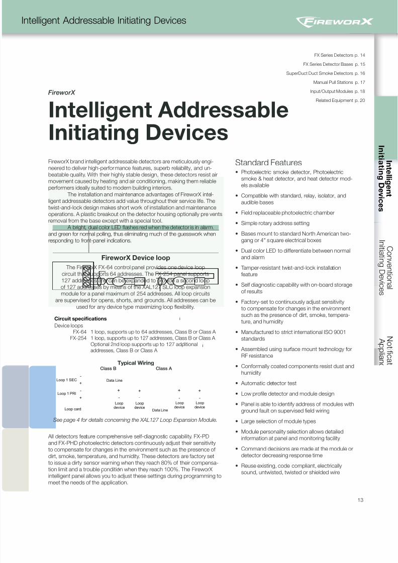
Intelligent AddressableInitiating DevicesFireworX brand intelligent addressable detectors are meticulously engi-
neered to deliver high-performance features, superb reliability, and un-
beatable quality. With their highly stable design, these detectors resist air
movement caused by heating and air conditioning, making them reliable
performers ideally suited to modern building interiors.
The installation and maintenance advantages of FireworX intel-ligent addressable detectors add value throughout their service life. The
twist-and-lock design makes short work of installation and maintenance
operations. A plastic breakout on the detector housing optionally prevents
removal from the base except with a special tool.
A bright, dual color LED flashes red when the detector is in alarm,
and green for normal polling, thus eliminating much of the guesswork when
responding to front-panel indications.
FireworX Device loop
The FireworX FX-64 control panel provides one device loop
circuit that supports 64 addresses. The FX-254 panel supports
127 addresses and can be expanded to provide a second loop
of 127 addresses by means of the XAL127 SLC loop expansion
module for a panel maximum of 254 addresses. All loop circuitsare supervised for opens, shorts, and grounds. All addresses can be
used for any device type maximizing loop flexibility.
Circuit specifications
Device loops
FX-64
FX-254
1 loop, supports up to 64 addresses, Class B or Class A
1 loop, supports up to 127 addresses, Class B or Class A
Optional 2nd loop supports up to 127 additional
addresses, Class B or Class A
Typical Wiring
Loop 1 SEC
Loop card
+
Loop 1 PRI +
+ +
Loopdevice
Loopdevice
Data Line
i ii
-
-
- -
i i
i
+ +
Loopdevice
Loopdevice
Data Line
- -
Class B Class A
See page 4 for details concerning the XAL127 Loop Expansion Module.
All detectors feature comprehensive self-diagnostic capability. FX-PD
and FX-PHD photoelectric detectors continuously adjust their sensitivity
to compensate for changes in the environment such as the presence of
dirt, smoke, temperature, and humidity. These detectors are factory set
to issue a dirty sensor warning when they reach 80% of their compensa-
tion limit and a trouble condition when they reach 100%. The FireworX
intelligent panel allows you to adjust these settings during programming to
meet the needs of the application.
Standard Features• Photoelectric smoke detector, Photoelectric
smoke & heat detector, and heat detector mod-
els available
• Compatible with standard, relay, isolator, andaudible bases
• Field replaceable photoelectric chamber
• Simple rotary address setting
• Bases mount to standard North American two-
gang or 4" square electrical boxes
• Dual color LED to differentiate between normal
and alarm
• Tamper-resistant twist-and-lock installation
feature
• Self diagnostic capability with on-board storage
of results
• Factory-set to continuously adjust sensitivity
to compensate for changes in the environment
such as the presence of dirt, smoke, tempera-
ture, and humidity
• Manufactured to strict international ISO 9001
standards
• Assembled using surface mount technology for
RF resistance
• Conformally coated components resist dust and
humidity
• Automatic detector test
• Low profile detector and module design
• Panel is able to identify address of modules with
ground fault on supervised field wiring
• Large selection of module types
• Module personality selection allows detailed
information at panel and monitoring facility
• Command decisions are made at the module or
detector decreasing response time
• Reuse existing, code compliant, electrically
sound, untwisted, twisted or shielded wire
8/10/2019 FX85005-0132 -- FireworX Submittal Guide
http://slidepdf.com/reader/full/fx85005-0132-fireworx-submittal-guide 22/56
I n i t i a t i n g
D e v i c e s
SUBMIT
C o n t r
o l P a n e l s
14
Intelligent Addressable Initiating Devices
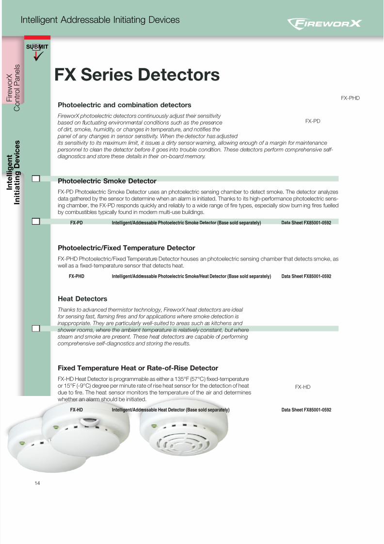
Photoelectric and combination detectors
FireworX photoelectric detectors continuously adjust their sensitivity
based on fluctuating environmental conditions such as the presence
of dirt, smoke, humidity, or changes in temperature, and notifies the
panel of any changes in sensor sensitivity. When the detector has adjusted
its sensitivity to its maximum limit, it issues a dirty sensor warning, allowing enough of a margin for maintenance
personnel to clean the detector before it goes into trouble condition. These detectors perform comprehensive self-
diagnostics and store these details in their on-board memory.
Photoelectric Smoke Detector
FX-PD Photoelectric Smoke Detector uses an photoelectric sensing chamber to detect smoke. The detector analyzesdata gathered by the sensor to determine when an alarm is initiated. Thanks to its high-performance photoelectric sens-
ing chamber, the FX-PD responds quickly and reliably to a wide range of fire types, especially slow burn ing fires fuelled
by combustibles typically found in modern multi-use buildings.
FX-PD Intelligent/Addressable Photoelectric Smoke Detector (Base sold separately) Data Sheet FX85001-0592
Photoelectric/Fixed Temperature Detector
FX-PHD Photoelectric/Fixed Temperature Detector houses an photoelectric sensing chamber that detects smoke, as
well as a fixed-temperature sensor that detects heat.
FX-PHD Intelligent/Addressable Photoelectric Smoke/Heat Detector (Base sold separately) Data Sheet FX85001-0592
Heat Detectors
Thanks to advanced thermistor technology, FireworX heat detectors are ideal
for sensing fast, flaming fires and for applications where smoke detection is
inappropriate. They are particularly well-suited to areas such as kitchens and
shower rooms, where the ambient temperature is relatively constant, but where
steam and smoke are present. These heat detectors are capable of performing
comprehensive self-diagnostics and storing the results.
Fixed Temperature Heat or Rate-of-Rise Detector
FX-HD Heat Detector is programmable as either a 135°F (57°C) fixed-temperatureor 15°F (-9°C) degree per minute rate of rise heat sensor for the detection of heat
due to fire. The heat sensor monitors the temperature of the air and determines
whether an alarm should be initiated.
FX-HD Intelligent/Addressable Heat Detector (Base sold separately) Data Sheet FX85001-0592
FX Series Detectors
FX-HD
FX-PD
FX-PHD
8/10/2019 FX85005-0132 -- FireworX Submittal Guide
http://slidepdf.com/reader/full/fx85005-0132-fireworx-submittal-guide 23/56
SUBMIT
15
Intelligent Addressable Initiating Devices
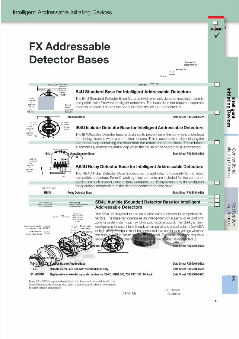
FX Addressable
Detector Bases
B4U Standard Base for Intelligent Addressable Detectors
The B4U Standard Detector Base features twist-and-lock detector installation and is
compatible with FireworX Intelligent detectors. The base does not require a separate
address because it shares the address of the device it is connected to.
B4U Standard Base Data Sheet FX85001-0592
Fromcontroller
orpreviousdevice
SLC n (-SLC in (+)
SLC out (-SLC out (+)
To nextdevice
TB2
IB4U Isolator Detector Base for Intelligent Addressable Detectors
The IB4U Isolator Detector Base is designed to prevent an entire communications loop
from being disabled when a short circuit occurs. This is accomplished by isolating the
part of the loop containing the short from the remainder of the circuit. These bases
automatically restore the entire loop when the cause of the short circuit is corrected.
IB4U Isolator Detector Base Data Sheet FX85001-0592
Fromcontroller
orpreviousdevice
SLC n (-SLC in (+)
SLC out (-SLC out (+)
To nextdevice
TB1
TB2
N/O COM N/C
RB4U Relay Detector Base for Intelligent Addressable Detectors
The RB4U Relay Detector Base is designed to add relay functionality to the listed
compatible detectors. Form C latching relay contacts are included for the control ofappliances such as door closers, fans, dampers, etc. Relay bases may be configured
for operation independent of the detector connected to the base.
RB4U Relay Detector Base Data Sheet FX85001-0592
Volume settingDefault = high volume
Cut for low volume
Tone settingDefault = temporal patternCut for steady tone
To configureoutput volume or
tone, cut thecircuit board as
shown
From power supplyor previous base
From controlleror previous device
To next baseor EOL relay
To next device
24 VDC (+)24 VDC (-)
24 VDC (+)24 VDC (-)
SLC out (-)SLC out (+)SLC in (-)
SLC in (+)
S IG + S IG - O UTI N I N/ OU T
DATA
SB4U Audible (Sounder) Detector Base for Intelligent
Addressable Detectors
The SB4U is designed to add an audible output function to compatible de-
tectors. The base can operate as an independent local alarm, or as part of a
zone or system alarm with synchronized audible output. The SB4U is field-
configurable for output tone (steady or temporal) and output volume (low dBA
or high dBA). The base must be connected to a continuous voltage whether
the output tone is set to steady or temporal. The base does not require a
separate address; it shares the address of the device it is connected to.
SB4U Audible (Sounder) Detector Base Data Sheet FX85001-0592
Accessories
AB4G-SB Surface Box for Audible Base Data Sheet FX85001-0592
R-LED Remote alarm LED. Use with standard base only. Data Sheet FX85001-0592
211-10PKG Replaceable smoke det. optical chamber for FX-PD, -PHD, 500, 700, TS7, FX7; 10-Pack Data Sheet FX85001-0592
Detector Trim ring
Gasket
6-32screws
Base plate
Compatibleelectrical box
- +
Maxmumresistanceper wiremust notexceed10 Ohms
Remote LED
SLC in (-)SLC in (+)
To nextdevice
SLC out (-)SLC out (+)
Fromcontroller
orpreviousdevice
AB4G-SB211 Optical
Chamber
Note: 211-10PKG replaceable optical chamber is not compatible with the
SuperDuct duct detector, optical beam detectors, and other smoke detec-
tors not listed in description
8/10/2019 FX85005-0132 -- FireworX Submittal Guide
http://slidepdf.com/reader/full/fx85005-0132-fireworx-submittal-guide 24/56
I n i t i a t i n g
D e v i c e s
SUBMIT
C o n t r
o l P a n e l s
16
Intelligent Addressable Initiating Devices
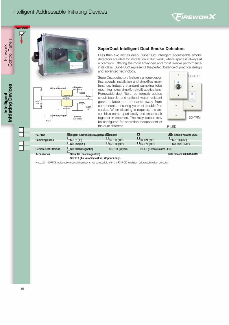
FX-PDD Intelligent Addressable SuperDuct Detector Data Sheet FX85001-0613
Sampling Tubes SD-T8 (8”) SD-T18 (18”) SD-T24 (24”) SD-T36 (36”)
SD-T42 (42”) SD-T60 (60”) SD-T78 (78”) SD-T120 (120”)
Remote Test Stations SD-TRM (magnetic) SD-TRK (keyed) R-LED (Remote alarm LED)
Accessories SD-MAG (Test magnet kit) Data Sheet FX85001-0613
SD-VTK (Air velocity test kit, stoppers only)
Note: 211-10PKG replaceable optical chamber is not compatible with the FX-PDD intelligent addressable duct detector
SuperDuct Intelligent Duct Smoke Detectors
Less than two inches deep, SuperDuct Intelligent addressable smokedetectors are ideal for installation in ductwork, where space is always at
a premium. Offering the most advanced and most reliable performance
in its class, SuperDuct represents the perfect balance of practical design
and advanced technology.
SuperDuct detectors feature a unique design
that speeds installation and simplifies main-
tenance. Industry standard sampling tube
mounting holes simplify retrofit applications.
Removable dust filters, conformally coated
circuit boards, and optional water-resistant
gaskets keep contaminants away from
components, ensuring years of trouble-free
service. When cleaning is required, the as-
semblies come apart easily and snap backtogether in seconds. The relay output may
be configured for operation independent of
the duct detector.
Returnair
Duct smokedetector
Supplyair
Duct smokedetector
Remotetest station
FACP
HVACunit
Alarm relay output
Alarm relay output
Remotetest station
SD-TRM
R-LED
SD-TRK
8/10/2019 FX85005-0132 -- FireworX Submittal Guide
http://slidepdf.com/reader/full/fx85005-0132-fireworx-submittal-guide 25/56
SUBMIT
17
Intelligent Addressable Initiating Devices
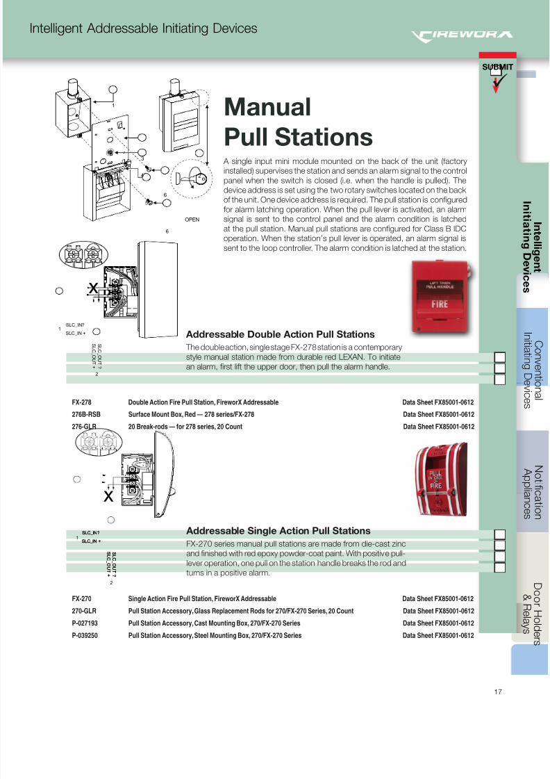
A single input mini module mounted on the back of the unit (factory
installed) supervises the station and sends an alarm signal to the control
panel when the switch is closed (i.e. when the handle is pulled). The
device address is set using the two rotary switches located on the back
of the unit. One device address is required. The pull station is configured
for alarm latching operation. When the pull lever is activated, an alarm
signal is sent to the control panel and the alarm condition is latched
at the pull station. Manual pull stations are configured for Class B IDC
operation. When the station’s pull lever is operated, an alarm signal is
sent to the loop controller. The alarm condition is latched at the station.
Addressable Double Action Pull Stations
The double action, single stage FX-278 station is a contemporary
style manual station made from durable red LEXAN. To initiate
an alarm, first lift the upper door, then pull the alarm handle.
FX-278 Double Action Fire Pull Station, FireworX Addressable Data Sheet FX85001-0612
276B-RSB Surface Mount Box, Red — 278 series/FX-278 Data Sheet FX85001-0612
276-GLR 20 Break-rods — for 278 series, 20 Count Data Sheet FX85001-0612
Addressable Single Action Pull Stations
FX-270 series manual pull stations are made from die-cast zincand finished with red epoxy powder-coat paint. With positive pull-
lever operation, one pull on the station handle breaks the rod and
turns in a positive alarm.
FX-270 Single Action Fire Pull Station, FireworX Addressable Data Sheet FX85001-0612
270-GLR Pull Station Accessory, Glass Replacement Rods for 270/FX-270 Series, 20 Count Data Sheet FX85001-0612
P-027193 Pull Station Accessory, Cast Mounting Box, 270/FX-270 Series Data Sheet FX85001-0612
P-039250 Pull Station Accessory, Steel Mounting Box, 270/FX-270 Series Data Sheet FX85001-0612
Manual
Pull Stations
SLC_IN?
SLC_IN +
S L C _ O UT ?
S L C _ O UT +
2
1
x
SLC_IN?
SLC_IN +
S L C _ O UT ?
S L C _ O UT +
SLC_IN?
SLC_IN +
S L C _ O UT ?
S L C _ O UT +
2
1
x
2
1
6
6
OPEN
3
4
5
8/10/2019 FX85005-0132 -- FireworX Submittal Guide
http://slidepdf.com/reader/full/fx85005-0132-fireworx-submittal-guide 26/56
I n i t i a t i n g
D e v i c e s
SUBMIT
C o n t r
o l P a n e l s
18
Intelligent Addressable Initiating Devices
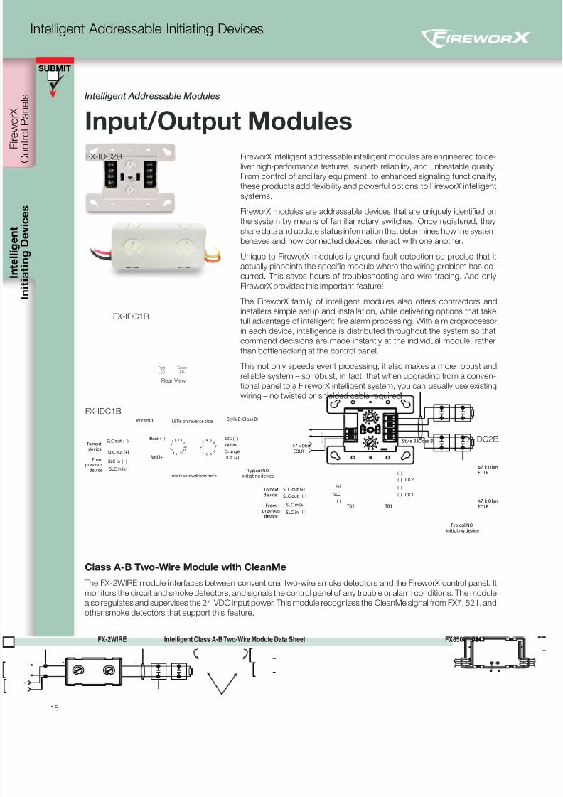
Intelligent Addressable Modules
Input/Output ModulesFireworX intelligent addressable intelligent modules are engineered to de-
liver high-performance features, superb reliability, and unbeatable quality.
From control of ancillary equipment, to enhanced signaling functionality,
these products add flexibility and powerful options to FireworX intelligent
systems.
FireworX modules are addressable devices that are uniquely identified on
the system by means of familiar rotary switches. Once registered, they
share data and update status information that determines how the system
behaves and how connected devices interact with one another.
Unique to FireworX modules is ground fault detection so precise that it
actually pinpoints the specific module where the wiring problem has oc-
curred. This saves hours of troubleshooting and wire tracing. And onlyFireworX provides this important feature!
The FireworX family of intelligent modules also offers contractors and
installers simple setup and installation, while delivering options that take
full advantage of intelligent fire alarm processing. With a microprocessor
in each device, intelligence is distributed throughout the system so that
command decisions are made instantly at the individual module, rather
than bottlenecking at the control panel.
This not only speeds event processing, it also makes a more robust and
reliable system – so robust, in fact, that when upgrading from a conven-
tional panel to a FireworX intelligent system, you can usually use existing
wiring – no twisted or shielded cable required!
FX-IDC1B
FX-IDC2B
47EOLR
k Ohm
47EOLR
k Ohm
IDC2
Style B (Class B)
IDC1
Typical NOinitiating device
TB2 TB1
(+)
(+)
SLC
(+)
( )
( )
( )
Frompreviousdevice
To nextdevice
SLC out (+)
SLC out
SLC in
SLC in (+)
( )
( )
Red (+) IDC (+)
Orange
IDC
Yellow
012
34
5 6
1211109
87
0 91
2
34 5
6
7
8
47EOLR
k Ohm
Typical NOinitiating device
Fromprevious
device
SLC in
SLC out
Wire nut
SLC in (+)
SLC out (+)
To nextdevice
Style B (Class B)
Black ( ) ( )( )
( )
Insert screwdriver here
LEDs on reverse side
FX-IDC1B
FX-IDC2B
Class A-B Two-Wire Module with CleanMe
The FX-2WIRE module interfaces between conventional two-wire smoke detectors and the FireworX control panel. It
monitors the circuit and smoke detectors, and signals the control panel of any trouble or alarm conditions. The module
also regulates and supervises the 24 VDC input power. This module recognizes the CleanMe signal from FX7, 521, and
other smoke detectors that support this feature.
FX-2WIRE Intelligent Class A-B Two-Wire Module Data Sheet FX85001-0611
Green
LED
Rear View
Red
LED
8/10/2019 FX85005-0132 -- FireworX Submittal Guide
http://slidepdf.com/reader/full/fx85005-0132-fireworx-submittal-guide 27/56
SUBMIT
19
Intelligent Addressable Initiating Devices
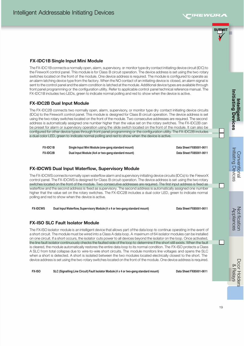
FX-IDCWS Dual Input Waterflow, Supervisory Module
The FX-IDCWS connects normally open waterflow alarm and supervisory initiating device circuits (IDCs) to the FireworX
control panel. The FX-IDCWS is designed for Class B circuit operation. The device address is set using the two rotary
switches located on the front of the module. Two consecutive addresses are required. The first input address is fixed as
waterflow and the second address is fixed as supervisory. The second address is automatically assigned one number
higher that the value set on the rotary switches. The FX-IDC2B includes a dual color LED, green to indicate normal
polling and red to show when the device is active.
FX-IDCWS Dual Input Waterflow, Supervisory Module (4 x 4 or two-gang standard mount) Data Sheet FX85001-0611
FX-ISO SLC Fault Isolator Module
The FX-ISO isolator module is an intelligent device that allows part of the data loop to continue operating in the event of
a short circuit. The module must be wired into a Class A data loop. A maximum of 64 isolator modules can be installed
on one circuit. If a short occurs, the isolator cuts power to all devices beyond the isolator on the loop. Once activated,
the line fault isolator continuously checks the faulted side of the loop to determine if the short still exists. When the faultis cleared, the module automatically restores the entire data loop to its normal condition. The FX-ISO protects a Class
A SLC from total collapse due to wire-to-wire short circuits. The module monitors line voltages and opens the SLC
when a short is detected. A short is isolated between the two modules located electrically closest to the short. The
device address is set using the two rotary switches located on the front of the module. One device address is required.
FX-ISO SLC (Signalling Line Circuit) Fault Isolator Module (4 x 4 or two-gang standard mount) Data Sheet FX85001-0611
FX-IDC1B Single Input Mini Module
The FX-IDC1B connects a normally open, alarm, supervisory, or monitor type dry contact initiating device circuit (IDC) to
the FireworX control panel. This module is for Class B circuit operation. The device address is set using the two rotary
switches located on the front of the module. One device address is required. The module is configured to operate as
an alarm latching device type from the factory. When the NO contact of an initiating device is closed, an alarm signal is
sent to the control panel and the alarm condition is latched at the module. Additional device types are available through
front panel programming or the configuration utility. Refer to applicable control panel technical reference manual. The
FX-IDC1B includes two LEDs, green to indicate normal polling and red to show when the device is active.
FX-IDC2B Dual Input Module
The FX-IDC2B connects two normally open, alarm, supervisory, or monitor type dry contact initiating device circuits
(IDCs) to the FireworX control panel. This module is designed for Class B circuit operation. The device address is set
using the two rotary switches located on the front of the module. Two consecutive addresses are required. The second
address is automatically assigned one number higher than the value set on the rotary switches. The FX-IDC2B can
be preset for alarm or supervisory operation using the slide switch located on the front of the module. It can also be
configured for other device types through front panel programming or the configuration utility. The FX-IDC2B includes
a dual color LED, green to indicate normal polling and red to show when the device is active.
FX-IDC1B Single Input Mini Module (one-gang standard mount) Data Sheet FX85001-0611
FX-IDC2B Dual Input Module (4x4 or two-gang standard mount) Data Sheet FX85001-0611
8/10/2019 FX85005-0132 -- FireworX Submittal Guide
http://slidepdf.com/reader/full/fx85005-0132-fireworx-submittal-guide 28/56
I n i t i a t i n g
D e v i c e s
SUBMIT
C o n t r
o l P a n e l s
20
Intelligent Addressable Initiating Devices
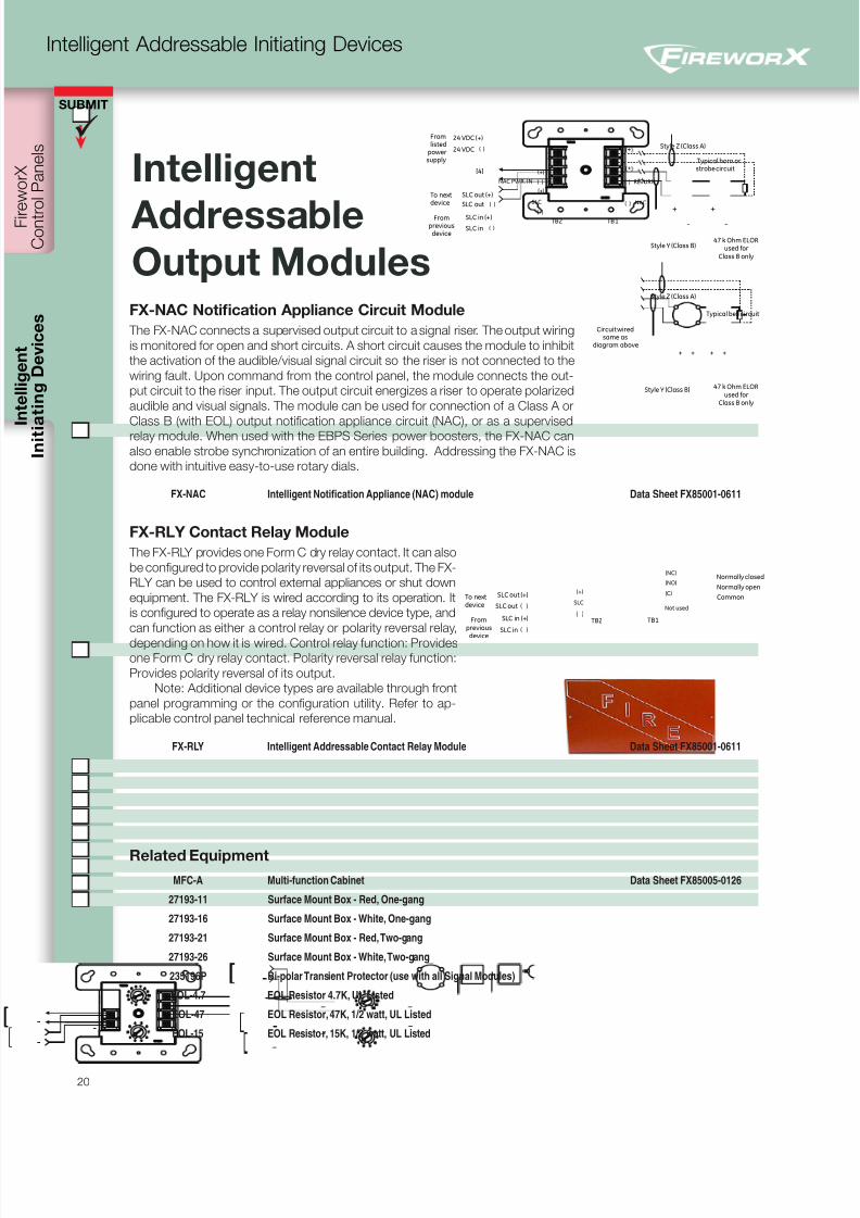
FX-NAC Notification Appliance Circuit Module
The FX-NAC connects a supervised output circuit to a signal riser. The output wiring
is monitored for open and short circuits. A short circuit causes the module to inhibit
the activation of the audible/visual signal circuit so the riser is not connected to the
wiring fault. Upon command from the control panel, the module connects the out-
put circuit to the riser input. The output circuit energizes a riser to operate polarized
audible and visual signals. The module can be used for connection of a Class A or
Class B (with EOL) output notification appliance circuit (NAC), or as a supervisedrelay module. When used with the EBPS Series power boosters, the FX-NAC can
also enable strobe synchronization of an entire building. Addressing the FX-NAC is
done with intuitive easy-to-use rotary dials.
FX-NAC Intelligent Notification Appliance (NAC) module Data Sheet FX85001-0611
FX-RLY Contact Relay Module
The FX-RLY provides one Form C dry relay contact. It can also
be configured to provide polarity reversal of its output. The FX-
RLY can be used to control external appliances or shut down
equipment. The FX-RLY is wired according to its operation. It
is configured to operate as a relay nonsilence device type, and
can function as either a control relay or polarity reversal relay,
depending on how it is wired. Control relay function: Providesone Form C dry relay contact. Polarity reversal relay function:
Provides polarity reversal of its output.
Note: Additional device types are available through front
panel programming or the configuration utility. Refer to ap-
plicable control panel technical reference manual.
FX-RLY Intelligent Addressable Contact Relay Module Data Sheet FX85001-0611
Related Equipment
MFC-A Multi-function Cabinet Data Sheet FX85005-0126
27193-11 Surface Mount Box - Red, One-gang
27193-16 Surface Mount Box - White, One-gang
27193-21 Surface Mount Box - Red, Two-gang
27193-26 Surface Mount Box - White, Two-gang
235196P Bi-polar Transient Protector (use with all Signal Modules)
EOL-4.7 EOL Resistor 4.7K, UL Listed
EOL-47 EOL Resistor, 47K, 1/2 watt, UL Listed
EOL-15 EOL Resistor, 15K, 1/2 watt, UL Listed
Fromlisted
powersupply
[4]
24 VDC (+)
24 VDC
Circuit wiredsame as
diagram above
Style Z (Class A)
Style Z (Class A)
Style Y (Class B)
Style Y (Class B)
Typical bell circuit
Typical horn orstrobe circuit
TB2 TB1
+ +
- -
+ +
- -
+ +
- -
RETURNNAC PWR. IN
NACSLC
(+)
(+)
Frompreviousdevice
To nextdevice
SLC out (+)
SLC out
SLC in
SLC in (+)
( )
( )
( ) ( )
( )
( )
( )
47 k Ohm ELORused for
Class B only
47 k Ohm ELORused for
Class B only
TB2 TB1Frompreviousdevice
SLC in (+)
SLC out (+)
SLC in
SLC out
To nextdevice
Normally open
Common
Not used
Normally closed
SLC
(+)
(NC)
(NO)
(C)
( )
( )
( )
Intelligent
AddressableOutput Modules
8/10/2019 FX85005-0132 -- FireworX Submittal Guide
http://slidepdf.com/reader/full/fx85005-0132-fireworx-submittal-guide 29/56
SUBMIT
21
Conventional Initiating Devices
Conventional
InitiatingDevices
500 Series Heat Detectors p. 21
700 Series Heat Detectors p. 22
Heat Detectors p. 24
SuperDuct Smoke Detectors p. 26
Beam Smoke Detectors p. 27
Carbon Monoxide Detector p. 28
Fire Alarm Stations p. 29
Explosionproof Stations p. 30
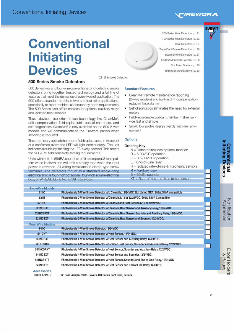
500 Series Smoke Detectors
500 Series two and four-wire conventional photoelectric smoke
detectors bring together trusted technology and a full line of
features that meet the demands of every type of application. The
500 offers sounder models in two and four-wire applications,
specifically to meet residential occupancy code requirements.
The 500 Series also offers choices for optional auxiliary relays
and isolated heat sensors.
These devices also offer proven technology like CleanMe®,
drift compensation, field replaceable optical chambers, and
self-diagnostics. CleanMe® is only available on the 500 2-wire
models and will communicate to the FireworX panels when
servicing is required.
The proprietary optical chamber is field replaceable. In the event
of a confirmed alarm the LED will light continuously. The unit
indicates trouble by flashing the LED every second. This meets
the NFPA 72 field sensitivity testing requirements.
Units with built-in 85dBA sounders emit a temporal 3 tone pat-
tern when in alarm and will emit a steady tone when the input
power is reversed. All wiring terminates in clamp-type screw
terminals. The detectors mount to a standard single-gang
electrical box, a four-inch octagonal, four-inch square electricalbox, or WIREMOLD(T) No. 5739 fixture box.
Two-Wire Models
511C Photoelectric 2-Wire Smoke Detector w/o CleanMe, 12/24VDC. Not Listed MEA. S09A, S10A compatible
521B Photoelectric 2-Wire Smoke Detector w/CleanMe, 6/12 or 12/24VDC. S09A, S10A Compatible
521BXT Photoelectric 2-Wire Smoke Detector w/CleanMe and Heat Sensor, 6/12 or 12/24VDC.
521NCRXT Photoelectric 2-Wire Smoke Detector w/CleanMe, Heat Sensor and Auxiliary Relay, 12/24VDC.
521NCSRXT Photoelectric 2-Wire Smoke Detector w/CleanMe, Heat Sensor, Sounder and Auxiliary Relay, 12/24VDC.
521NCSXT Photoelectric 2-Wire Smoke Detector w/CleanMe, Heat Sensor and Sounder, 12/24VDC.
Four Wire Models
541C Photoelectric 4-Wire Smoke Detector, 12/24VDC
541CXT Photoelectric 4-Wire Smoke Detector w/Heat Sensor, 12/24VDC.
541NCRXT Photoelectric 4-Wire Smoke Detector w/Heat Sensor and Auxiliary Relay, 12/24VDC.
541NCSRH Photoelectric 4-Wire Smoke Detector w/Isolated Heat Sensor, Sounder and Auxiliary Relay, 12/24VDC.
541NCSRXT Photoelectric 4-Wire Smoke Detector w/Heat Sensor, Sounder and Auxiliary Relay, 12/24VDC.
541NCSXT Photoelectric 4-Wire Smoke Detector w/Heat Sensor and Sounder, 12/24VDC.
541NCSXTE Photoelectric 4-Wire Smoke Detector w/Heat Sensor, Sounder, and End of Line Relay, 12/24VDC.
541NCXTE Photoelectric 4-Wire Smoke Detector w/Heat Sensor and End of Line Relay, 12/24VDC.
Accessories
500-PLT-5PKG 6” Base Adapter Plate. Covers 400 Series Foot Print, 5-Pack.
Standard Features
• CleanMe® remote maintenance reporting
(2-wire models) and built-in drift compensation
reduces false alarms
• Self-diagnostics eliminates the need for external
meters
• Field-replaceable optical chamber makes ser-vice fast and simple
• Small, low profile design blends with any envi-
ronment
Options
Ordering Key
N = Detector includes optional function
B = 6-33VDC operation
C = 8.5-33VDC operation
E = End-of-Line relay
H = Isolated rate-of-rise & fixed temp sensors
R = Auxiliary relay
S = 85dBa sounder XT = Rate-of-rise and fixed temp sensors
521B Smoke Detector
8/10/2019 FX85005-0132 -- FireworX Submittal Guide
http://slidepdf.com/reader/full/fx85005-0132-fireworx-submittal-guide 30/56
C o n t r
o l P a n e l s
I n i t i a t i n g D e v i c e s
I n
i t i a t i n g
D e v i c e s
SUBMIT
22
Conventional Initiating Devices
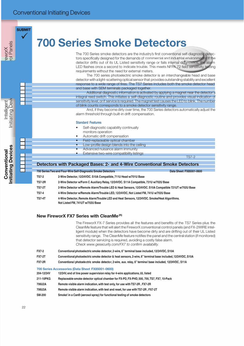
700 Series Smoke Detectors The 700 Series smoke detectors are the industry’s first conventional self-diagnostic detec-
tors specifically designed for the demands of commercial and industrial environments. If the
detector drifts out of its UL Listed sensitivity range or fails internal diagnostics, the alarm
LED flashes once a second to indicate trouble. This meets NFPA 72 field sensitivity testing
requirements without the need for external meters.
The 700 series photoelectric smoke detector is an interchangeable head and base
detector with a light-scattering optical sensor that provides outstanding stability and excellent
response to a wide range of fires. The TS7 Series includes both the smoke detector head
and base with SEM terminals packaged together.
Additional diagnostic information is activated by applying a magnet near the detector’s
integral reed switch. This initiates a self-diagnostic routine and provides visual indication of
sensitivity level, or if service is required. The magnet test causes the LED to blink. The number
of blink counts corresponds to a smoke detector sensitivity range.
And, if they become dirty over time, the 700 Series detectors automatically adjust the
alarm threshold through built-in drift compensation.
Standard Features
• Self-diagnostic capability continually
monitors operation
• Automatic drift compensation
• Field-replaceable optical chamber
• Low-profile design blends into the ceiling
• Advanced nuisance alarm immunity
• Extensive two-wire compatibility listings
Detectors with Packaged Bases: 2- and 4-Wire Conventional Smoke Detectors
700 Series Two and Four-Wire Self-Diagnostic Smoke Detectors Data Sheet: FX85001-0600
TS7-2 2-Wire Detector, 12/24VDC. S10A Compatible, 711U Head w/701U Base
TS7-2R 2-Wire Detector w/Form C Auxiliary Relay, 12/24VDC. S11A Compatible, 731U w/702U Base
TS7-2T 2-Wire Detector w/Remote Alarm/Trouble LED & Heat Sensors, 12/24VDC. S10A Compatible 721UT w/702U Base
TS7-4 4-Wire Detector w/Remote Alarm/Trouble LED, 12/24VDC, Not Listed FM, 741U w/702U Base
TS7-4T 4-Wire Detector, Remote Alarm/Trouble LED and Heat Sensors, 12/24VDC. Smoke/Heat Algorithms.
Not Listed FM, 741UT w/702U Base
New FireworX FX7 Series with CleanMe(R)
The FireworX FX-7 Series provides all the features and benefits of the TS7 Series plus the
CleanMe feature that will alert the FireworX conventional control panels (and FX-2WIRE intel-
ligent module) when the detectors have become dirty and are drifting out of their UL Listed
sensitivity range. The CleanMe feature notifies the panel and the central station (if monitored)
that detector servicing is required, avoiding a costly false alarm.
Check www.gesecurity.com/FX7 to confirm availability.
FX7-2 Conventional photoelectric smoke detector, 2-wire, 6” terminal base included, 12/24VDC, S10A
FX7-2T Conventional photoelectric smoke detector & heat sensors, 2-wire, 6” terminal base included, 12/24VDC, S10A
FX7-2R Conventional photoelectric smoke detector, 2-wire, aux. relay, 6” terminal base included, 12/24VDC, S11A
700 Series Accessories (Data Sheet FX85001-0600)
204-12/24V 12/24V, end of line power supervision relay for 4-wire applications, UL listed
211-10PKG Replaceable smoke detector optical chamber for FX-PD, FX-PHD, 500, 700, TS7, FX7, 10-Pack
706U2A Remote visible alarm indication, with test only, for use with TS7-2R , FX7-2R
706U3A Remote visible alarm indication, with test and reset, for use with TS7-2R , FX7-2T
SM-200 Smoke! in a Can® (aerosol spray) for functional testing of smoke detectors
TS7-2
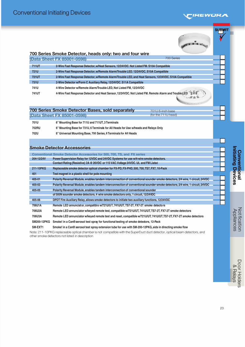
8/10/2019 FX85005-0132 -- FireworX Submittal Guide
http://slidepdf.com/reader/full/fx85005-0132-fireworx-submittal-guide 31/56
SUBMIT
23
Conventional Initiating Devices
700 Series Smoke Detector, heads only: two and four wire
(Data Sheet FX 85001-0598) 711UT 2-Wire Fast Response Detector, w/Heat Sensors, 12/24VDC. Not Listed FM. S10A Compatible
721U 2-Wire Fast Response Detector, w/Remote Alarm/Trouble LED. 12/24VDC, S10A Compatible
721UT 2-Wire Fast Response Detector, w/Remote Alarm/Trouble LED, and Heat Sensors, 12/24VDC. S10A Compatible
731U 2-Wire Detector w/Form C Auxiliary Relay, 12/24VDC. S11A Compatible
741U 4-Wire Detector w/Remote Alarm/Trouble LED, Not Listed FM, 12/24VDC
741UT 4-Wire Fast Response Detector and Heat Sensor, 12/24VDC. Not Listed FM. Remote Alarm and Trouble LED
700 Series Smoke Detector Bases, sold separately
(Data Sheet FX 85001-0598)
701U 6” Mounting Base for 711U and 711UT, 3 Terminals
702RU 6” Mounting Base for 731U, 6 Terminals for All Heads for Use w/heads and Relays Only
702U 6” Universal Mounting Base, 700 Series, 6 Terminals for All Heads
Smoke Detector Accessories
Conventional Smoke Detector Accessories for 500, 700, TS, and FX series
204-12/24V Power Supervision Relay for 12VDC and 24VDC Systems for use w/4-wire smoke detectors.
Contact Rating (Resistive) 2A @ 26VDC or 115 VAC. Voltage 24VDC. UL and FM Listed
211-10PKG Replaceable smoke detector optical chamber for FX-PD, FX-PHD, 500, 700, TS7, FX7, 10-Pack
401 Test magnet in a plastic shell for pole mounting
405-01 Polarity Reversal Module, enables tandem interconnection of conventional sounder smoke detectors, 2/4 wire, 1 circuit, 24VDC
405-03 Polarity Reversal Module, enables tandem interconnection of conventional sounder smoke detectors, 2/4 wire, 1 circuit, 24VDC
405-05 Polarity Reversal Module, enables tandem interconnection of conventional sounder
of 500N sounder smoke detectors, 4 wire smoke detectors only, 1 circuit, 12/24VDC
405-06 DPDT Fire Auxiliary Relay, allows smoke detectors to initiate two auxiliary functions, 12/24VDC
706U1A Remote LED annunciator, compatible w/721U/UT, 741U/UT, TS7-2T, FX7-2T smoke detectors
706U2A Remote LED annunciator w/keyed remote test, compatible w/721U/UT, 741U/UT, TS7-2T, FX7-2T smoke detectors
706U3A Remote LED annunciator w/keyed remote test and reset, compatible w/721U/UT, 741U/UT, TS7-2T, FX7-2T smoke detectors
SM200-12PKG Smoke! in a Can® aerosol test spray for functional testing of smoke detectors, 12-Pack
SM-EXT1 Smoke! in a Can® aerosol test spray extension tube for use with SM-200-12PKG, aids in directing smoke flow
Note: 211-10PKG replaceable optical chamber is not compatible with the SuperDuct duct detector, optical beam detectors, and
other smoke detectors not listed in description
701U 6-inch base
(for the 711U head)
700 Series
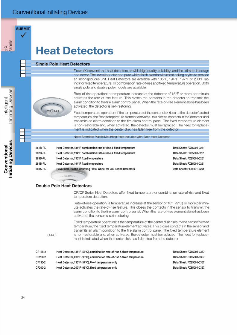
8/10/2019 FX85005-0132 -- FireworX Submittal Guide
http://slidepdf.com/reader/full/fx85005-0132-fireworx-submittal-guide 32/56
C o n t r
o l P a n e l s
I n i t i a t i n g D e v i c e s
I n
i t i a t i n g
D e v i c e s
SUBMIT
24
Conventional Initiating Devices
Heat DetectorsSingle Pole Heat Detectors
FireworX conventional heat detectors provide high quality, reliability, and the ultimate in design
and decor. The low si lhouette and pure white finish blends with most ceiling styles to provide
an inconspicuous unit. Heat Detectors are available with 135°F, 194°F, 197°F or 200°F rat-
ings for fixed temperature, or combination rate-of-rise and fixed temperature operation. Both
single pole and double pole models are available.
Rate-of-rise operation: a temperature increase at the detector of 15°F or more per minute
activates the rate-of-rise feature. This closes the contacts in the detector to transmit the
alarm condition to the fire alarm control panel. When the rate-of-rise element alone has been
activated, the detector is self-restoring.
Fixed temperature operation: if the temperature of the center disk rises to the detector’s rated
temperature, the fixed temperature element activates. this closes contacts in the detector andtransmits an alarm condition to the fire alarm control panel. The fixed temperature element
is non-restorable and, when activated, the detector must be replaced. The need for replace-
ment is indicated when the center disk has fallen free from the detector.
Note: Standard Plastic Mounting Plate Included with Each Heat Detector
281B-PL Heat Detector, 135°F, combination rate-of-rise & fixed temperature Data Sheet: FX85001-0261
282B-PL Heat Detector, 194°F, combination rate-of-rise & fixed temperature Data Sheet: FX85001-0261
283B-PL Heat Detector, 135°F, fixed temperature Data Sheet: FX85001-0261
284B-PL Heat Detector, 194°F, fixed temperature Data Sheet: FX85001-0261
280A-PL Reversible Plastic Mounting Plate, White, for 280 Series Detectors Data Sheet: FX85001-0261
Double Pole Heat Detectors
CR/CF Series Heat Detectors offer fixed temperature or combination rate-of-rise and fixed
temperature detection.
Rate-of-rise operation: a temperature increase at the sensor of 15°F (9°C) or more per min-
ute activates the rate-of-rise feature. This closes the contacts in the sensor to transmit the
alarm condition to the fire alarm control panel. When the rate-of-rise element alone has been
activated, the sensor is self-restoring.
Fixed temperature operation: if the temperature of the center disk rises to the sensor’s rated
temperature, the fixed temperature element activates. This closes contacts in the sensor and
transmits an alarm condition to the fire alarm control panel. The fixed temperature element
is non-restorable and, when activated, the detector must be replaced. The need for replace-ment is indicated when the center disk has fallen free from the detector.
CR135-2 Heat Detector, 135°F (57°C), combination rate-of-rise & fixed temperature Data Sheet: FX85001-0367
CR200-2 Heat Detector, 200°F (93°C), combination rate-of-rise & fixed temperature Data Sheet: FX85001-0367
CF135-2 Heat Detector, 135°F (57°C), fixed temperature only Data Sheet: FX85001-0367
CF200-2 Heat Detector, 200°F (93°C), fixed temperature only Data Sheet: FX85001-0367
280B-PL
CR-CF
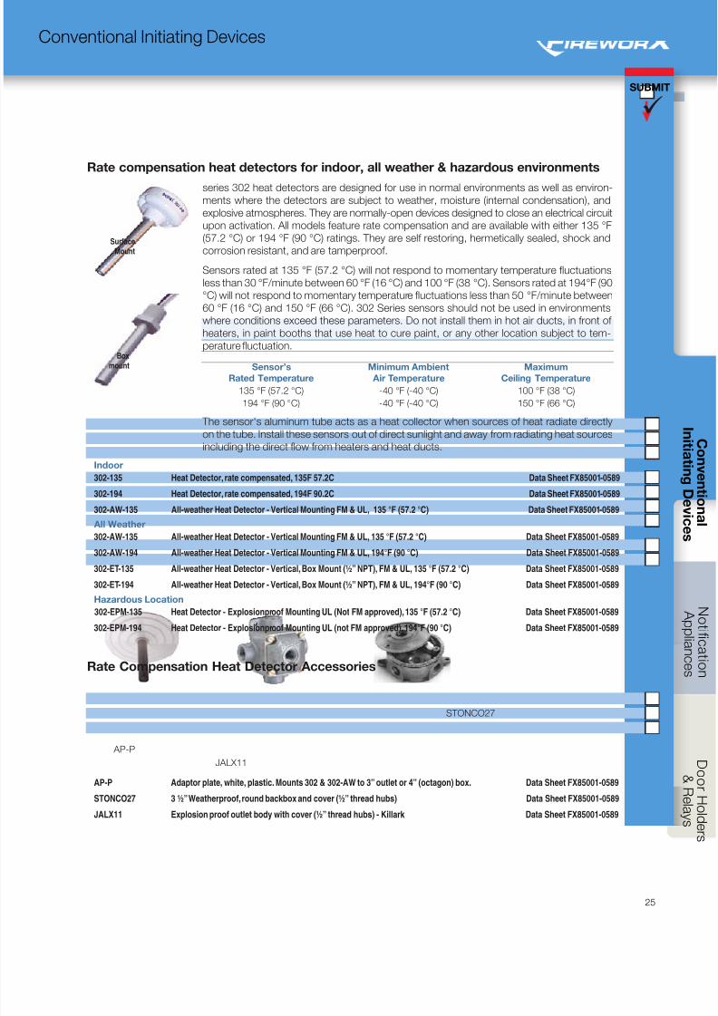
8/10/2019 FX85005-0132 -- FireworX Submittal Guide
http://slidepdf.com/reader/full/fx85005-0132-fireworx-submittal-guide 33/56
SUBMIT
25
Conventional Initiating Devices
Rate compensation heat detectors for indoor, all weather & hazardous environments
series 302 heat detectors are designed for use in normal environments as well as environ-
ments where the detectors are subject to weather, moisture (internal condensation), and
explosive atmospheres. They are normally-open devices designed to close an electrical circuit
upon activation. All models feature rate compensation and are available with either 135 °F
(57.2 °C) or 194 °F (90 °C) ratings. They are self restoring, hermetically sealed, shock and
corrosion resistant, and are tamperproof.
Sensors rated at 135 °F (57.2 °C) will not respond to momentary temperature fluctuations
less than 30 °F/minute between 60 °F (16 °C) and 100 °F (38 °C). Sensors rated at 194°F (90
°C) will not respond to momentary temperature fluctuations less than 50 °F/minute between
60 °F (16 °C) and 150 °F (66 °C). 302 Series sensors should not be used in environments
where conditions exceed these parameters. Do not install them in hot air ducts, in front of
heaters, in paint booths that use heat to cure paint, or any other location subject to tem-
perature fluctuation.
Sensor’s
Rated Temperature
Minimum Ambient
Air Temperature
Maximum
Ceiling Temperature
135 °F (57.2 °C) -40 °F (-40 °C) 100 °F (38 °C)
194 °F (90 °C) -40 °F (-40 °C) 150 °F (66 °C)
The sensor's aluminum tube acts as a heat collector when sources of heat radiate directly
on the tube. Install these sensors out of direct sunlight and away from radiating heat sources
including the direct flow from heaters and heat ducts.
Indoor
302-135 Heat Detector, rate compensated, 135F 57.2C Data Sheet FX85001-0589
302-194 Heat Detector, rate compensated, 194F 90.2C Data Sheet FX85001-0589
302-AW-135 All-weather Heat Detector - Vertical Mounting FM & UL, 135 °F (57.2 °C) Data Sheet FX85001-0589
All Weather
302-AW-135 All-weather Heat Detector - Vertical Mounting FM & UL, 135 °F (57.2 °C) Data Sheet FX85001-0589
302-AW-194 All-weather Heat Detector - Vertical Mounting FM & UL, 194°F (90 °C) Data Sheet FX85001-0589
302-ET-135 All-weather Heat Detector - Vertical, Box Mount (½” NPT), FM & UL, 135 °F (57.2 °C) Data Sheet FX85001-0589
302-ET-194 All-weather Heat Detector - Vertical, Box Mount (½” NPT), FM & UL, 194°F (90 °C) Data Sheet FX85001-0589
Hazardous Location
302-EPM-135 Heat Detector - Explosionproof Mounting UL (Not FM approved), 135 °F (57.2 °C) Data Sheet FX85001-0589
302-EPM-194 Heat Detector - Explosionproof Mounting UL (not FM approved), 194°F (90 °C) Data Sheet FX85001-0589
Rate Compensation Heat Detector Accessories
AP-P Adaptor plate, white, plastic. Mounts 302 & 302-AW to 3” outlet or 4” (octagon) box. Data Sheet FX85001-0589
STONCO27 3 ½” Weatherproof, round backbox and cover (½” thread hubs) Data Sheet FX85001-0589
JALX11 Explosion proof outlet body with cover (½” thread hubs) - Killark Data Sheet FX85001-0589
SurfaceMount
Boxmount
STONCO27
AP-P
JALX11
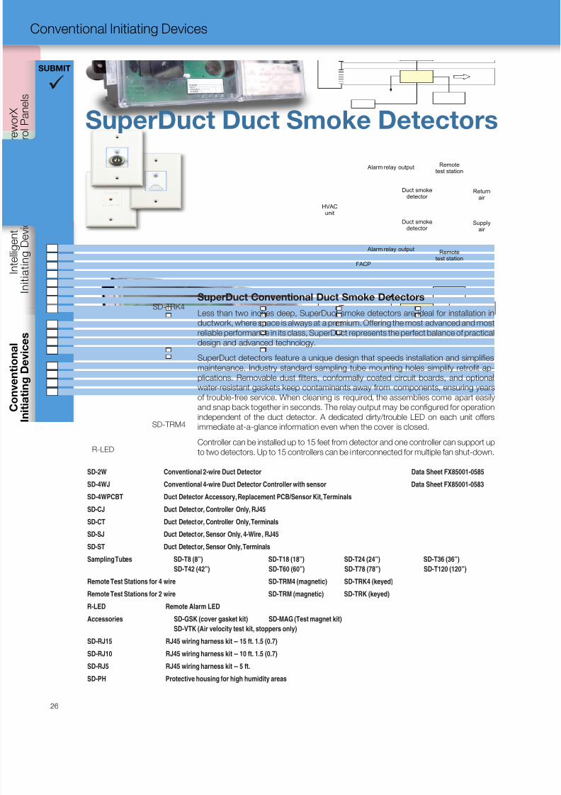
8/10/2019 FX85005-0132 -- FireworX Submittal Guide
http://slidepdf.com/reader/full/fx85005-0132-fireworx-submittal-guide 34/56
C o n t r
o l P a n e l s
I n i t i a t i n g D e v i c e s
I n
i t i a t i n g
D e v i c e s
SUBMIT
26
Conventional Initiating Devices
SD-2W Conventional 2-wire Duct Detector Data Sheet FX85001-0585
SD-4WJ Conventional 4-wire Duct Detector Controller with sensor Data Sheet FX85001-0583
SD-4WPCBT Duct Detector Accessory, Replacement PCB/Sensor Kit, Terminals
SD-CJ Duct Detector, Controller Only, RJ45
SD-CT Duct Detector, Controller Only, Terminals
SD-SJ Duct Detector, Sensor Only, 4-Wire, RJ45
SD-ST Duct Detector, Sensor Only, Terminals
Sampling Tubes SD-T8 (8”) SD-T18 (18”) SD-T24 (24”) SD-T36 (36”)SD-T42 (42”) SD-T60 (60”) SD-T78 (78”) SD-T120 (120”)
Remote Test Stations for 4 wire SD-TRM4 (magnetic) SD-TRK4 (keyed)
Remote Test Stations for 2 wire SD-TRM (magnetic) SD-TRK (keyed)
R-LED Remote Alarm LED
Accessories SD-GSK (cover gasket kit) SD-MAG (Test magnet kit)
SD-VTK (Air velocity test kit, stoppers only)
SD-RJ15 RJ45 wiring harness kit -- 15 ft. 1.5 (0.7)
SD-RJ10 RJ45 wiring harness kit -- 10 ft. 1.5 (0.7)
SD-RJ5 RJ45 wiring harness kit -- 5 ft.
SD-PH Protective housing for high humidity areas
SuperDuct Conventional Duct Smoke Detectors
Less than two inches deep, SuperDuct smoke detectors are ideal for installation in
ductwork, where space is always at a premium. Offering the most advanced and most
reliable performance in its class, SuperDuct represents the perfect balance of practical
design and advanced technology.
SuperDuct detectors feature a unique design that speeds installation and simplifies
maintenance. Industry standard sampling tube mounting holes simplify retrofit ap-
plications. Removable dust filters, conformally coated circuit boards, and optional
water-resistant gaskets keep contaminants away from components, ensuring years
of trouble-free service. When cleaning is required, the assemblies come apart easily
and snap back together in seconds. The relay output may be configured for operation
independent of the duct detector. A dedicated dirty/trouble LED on each unit offersimmediate at-a-glance information even when the cover is closed.
Controller can be installed up to 15 feet from detector and one controller can support up
to two detectors. Up to 15 controllers can be interconnected for multiple fan shut-down.
Returnair
Duct smokedetector
Supplyair
Duct smokedetector
Remotetest station
FACP
HVACunit
Alarm relay output
Alarm relay output
Remotetest station
SuperDuct Duct Smoke Detectors
SD-TRM4
R-LED
SD-TRK4
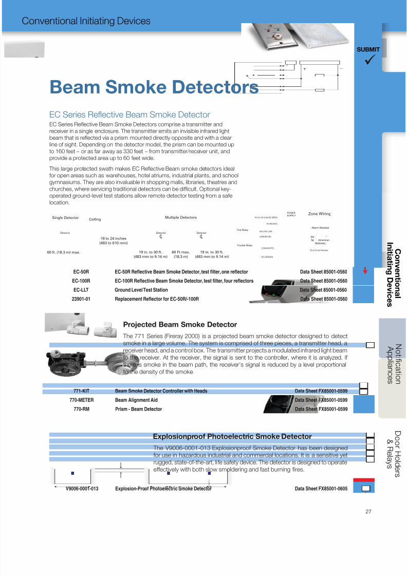
8/10/2019 FX85005-0132 -- FireworX Submittal Guide
http://slidepdf.com/reader/full/fx85005-0132-fireworx-submittal-guide 35/56
SUBMIT
27
Conventional Initiating Devices
Single Detector Multiple Detectors
60 ft. (18.3 m) max.
19 to 24 inches
(483 to 610 mm)
19 in. to 30 ft.
(483 mm to 9.14 m)
60 Ft max.
(18.3 m)
19 in. to 30 ft.
(483 mm to 9.14 m)
Ceiling
Detector Detector Detector
CL CL
EC Series Reflective Beam Smoke DetectorEC Series Reflective Beam Smoke Detectors comprise a transmitter and
receiver in a single enclosure. The transmitter emits an invisible infrared light
beam that is reflected via a prism mounted directly opposite and with a clear
line of sight. Depending on the detector model, the prism can be mounted up
to 160 feet – or as far away as 330 feet – from transmitter/receiver unit, and
provide a protected area up to 60 feet wide.
This large protected swath makes EC Reflective Beam smoke detectors ideal
for open areas such as warehouses, hotel atriums, industrial plants, and school
gymnasiums. They are also invaluable in shopping malls, libraries, theatres and
churches, where servicing traditional detectors can be difficult. Optional key-
operated ground-level test stations allow remote detector testing from a safe
location.
End of Line Resistor
Alarm Resistor
COM (BLUE)
NO (YELLOW)
COM (WHITE)
NC (GREEN)
Fire Relay
Trouble Relay
10.2 to 30 Volts DC (RED)
0V (BLACK)
POWER
SUPPLY Zone Wiring
Alarm Resistor
(Not required for
North American
Markets)
EC-50R EC-50R Reflective Beam Smoke Detector, test filter, one reflector Data Sheet 85001-0560
EC-100R EC-100R Reflective Beam Smoke Detector, test filter, four reflectors Data Sheet 85001-0560
EC-LLT Ground Level Test Station Data Sheet 85001-0560
23901-01 Replacement Reflector for EC-50R/-100R Data Sheet 85001-0560
Beam Smoke Detectors
Explosionproof Photoelectric Smoke Detector
The V9006-0001-013 Explosionproof Smoke Detector has been designed
for use in hazardous industrial and commercial locations. It is a sensitive yet
rugged, state-of-the-art, life safety device. The detector is designed to operate
effectively with both slow smoldering and fast burning fires.
V9006-0001-013 Explosion-Proof Photoelectric Smoke Detector Data Sheet FX85001-0605
Projected Beam Smoke Detector
The 771 Series (Fireray 2000) is a projected beam smoke detector designed to detect
smoke in a large volume. The system is comprised of three pieces, a transmitter head, a
receiver head, and a control box. The transmitter projects a modulated infrared light beam
to the receiver. At the receiver, the signal is sent to the controller, where it is analyzed. If
there is smoke in the beam path, the receiver’s signal is reduced by a level proportional
to the density of the smoke.
771-KIT Beam Smoke Detector Controller with Heads Data Sheet FX85001-0599
770-METER Beam Alignment Aid Data Sheet FX85001-0599
770-RM Prism - Beam Detector Data Sheet FX85001-0599
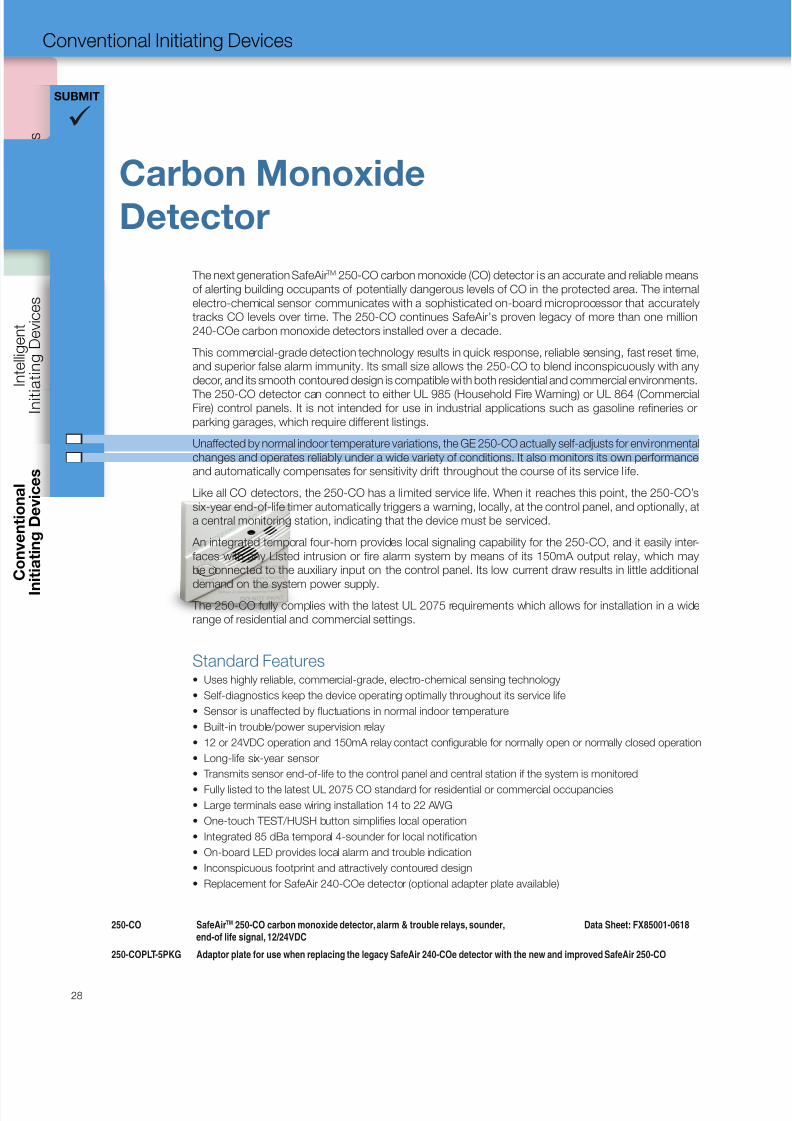
8/10/2019 FX85005-0132 -- FireworX Submittal Guide
http://slidepdf.com/reader/full/fx85005-0132-fireworx-submittal-guide 36/56
C o n t r
o l P a n e l s
I n i t i a t i n g D e v i c e s
I n
i t i a t i n g
D e v i c e s
SUBMIT
28
Conventional Initiating Devices
The next generation SafeAir TM 250-CO carbon monoxide (CO) detector is an accurate and reliable means
of alerting building occupants of potentially dangerous levels of CO in the protected area. The internal
electro-chemical sensor communicates with a sophisticated on-board microprocessor that accurately
tracks CO levels over time. The 250-CO continues SafeAir’s proven legacy of more than one million
240-COe carbon monoxide detectors installed over a decade.
This commercial-grade detection technology results in quick response, reliable sensing, fast reset time,
and superior false alarm immunity. Its small size allows the 250-CO to blend inconspicuously with any
decor, and its smooth contoured design is compatible with both residential and commercial environments.
The 250-CO detector can connect to either UL 985 (Household Fire Warning) or UL 864 (CommercialFire) control panels. It is not intended for use in industrial applications such as gasoline refineries or
parking garages, which require different listings.
Unaffected by normal indoor temperature variations, the GE 250-CO actually self-adjusts for environmental
changes and operates reliably under a wide variety of conditions. It also monitors its own performance
and automatically compensates for sensitivity drift throughout the course of its service l ife.
Like all CO detectors, the 250-CO has a limited service life. When it reaches this point, the 250-CO’s
six-year end-of-life timer automatically triggers a warning, locally, at the control panel, and optionally, at
a central monitoring station, indicating that the device must be serviced.
An integrated temporal four-horn provides local signaling capability for the 250-CO, and it easily inter-
faces with any Listed intrusion or fire alarm system by means of its 150mA output relay, which may
be connected to the auxiliary input on the control panel. Its low current draw results in little additional
demand on the system power supply. The 250-CO fully complies with the latest UL 2075 requirements which allows for installation in a wide
range of residential and commercial settings.
Standard Features• Uses highly reliable, commercial-grade, electro-chemical sensing technology
• Self-diagnostics keep the device operating optimally throughout its service life
• Sensor is unaffected by fluctuations in normal indoor temperature
• Built-in trouble/power supervision relay
• 12 or 24VDC operation and 150mA relay contact configurable for normally open or normally closed operation
• Long-life six-year sensor
• Transmits sensor end-of-life to the control panel and central station if the system is monitored
• Fully listed to the latest UL 2075 CO standard for residential or commercial occupancies
• Large terminals ease wiring installation 14 to 22 AWG
• One-touch TEST/HUSH button simplifies local operation
• Integrated 85 dBa temporal 4-sounder for local notification
• On-board LED provides local alarm and trouble indication
• Inconspicuous footprint and attractively contoured design
• Replacement for SafeAir 240-COe detector (optional adapter plate available)
250-CO SafeAirTM 250-CO carbon monoxide detector, alarm & trouble relays, sounder, Data Sheet: FX85001-0618 end-of life signal, 12/24VDC
250-COPLT-5PKG Adaptor plate for use when replacing the legacy SafeAir 240-COe detector with the new and improved SafeAir 250-CO
Carbon Monoxide
Detector
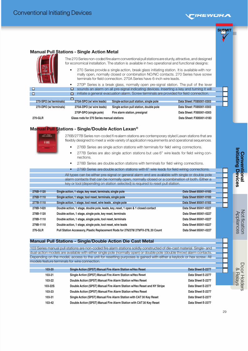
8/10/2019 FX85005-0132 -- FireworX Submittal Guide
http://slidepdf.com/reader/full/fx85005-0132-fireworx-submittal-guide 37/56
SUBMIT
29
Conventional Initiating Devices
Manual Pull Stations - Single Action Metal
The 270 Series non-coded fire alarm conventional pull stations are sturdy, attractive, and designed
for economical installation. The station is available in two operational and functional designs:
• 270 Series provide a single action, break glass initiating station. It is available with nor-
mally open, normally closed or combination NO/NC contacts. 270 Series have screw
terminals for field connection. 270A Series have 6-inch wire leads.
• 270P Series is a break glass, normally open pre-signal station. The pull of the lever
sounds an alarm on all pre-signal indicating devices. Inserting a key and turning it will
initiate a general evacuation alarm. Screw terminals are provided for field connection.
270-SPO (w/ terminals) 270A-SPO (w/ wire leads) Single-action pull station, single pole Data Sheet: FX85001-0303
270-DPO (w/ terminals) 270A-DPO (w/ wire leads) Single action pull station, double pole Data Sheet: FX85001-0303
270P-SPO (single pole) Fire alarm station, presignal Data Sheet: FX85001-0303
270-GLR Glass rods for 270 Series manual stations Data Sheet: FX85001-0183
Manual Pull Stations - Single/Double Action Lexan®
276B/277B Series non-coded fi re alarm stations are contemporary styled Lexan stations that are
flexibly designed to meet a wide variety of application requirements and operational sequences.
• 276B Series are single action stations with terminals for field wiring connections.
• 277B Series are also single action stations but use 6” wire leads for field wiring con-
nections.
• 278B Series are double action stations with terminals for field wiring connections.
• 279B Series are double action stations with 6” wire leads for field wiring connections.
All types can be either pre-signal or general alarm and are available with single or double pole
alarm contacts that can be normally open, normally closed or a combination of both. Either a
key or tool (depending on station selected) is required to reset pull station.
276B-1120 Single action, 1 stage, key reset, terminals, single pole Data Sheet 85001-0183
276B-1110 Single action, 1 stage, tool reset, terminals, single pole Data Sheet 85001-0183
277B-1110 Single action, 1 stage, tool reset, wire leads , single pole Data Sheet 85001-0183
278B-1420 Double action, 1 stage, double pole, leads, key, reset, 1 open & 1 closed contact Data Sheet 85001-0227
278B-1120 Double action, 1 stage, single pole, key reset, terminals Data Sheet 85001-0227
278B-1110 Double action, 1 stage, single pole, tool reset, terminals Data Sheet 85001-0227
279B-1110 Double action, 1 stage, single pole, tool reset, wire leads Data Sheet 85001-0227
276-GLR Pull Station Accessory, Plastic Replacement Rods for 276/278/ 279/FX-278, 20 Count Data Sheet 85001-0227
Manual Pull Stations - Single/Double Action Die Cast Metal
103 Series manual pull stations are non-coded fire alarm stations solidly constructed of die-cast material. Single- and
dual-action models are available with either single pole (normally open) or double pole (double throw) alarm contacts.
Depending on the model, access to the unit for resetting purposes is gained with either a keylock or hex screw. All
models feature terminals for wire connection.
103-20 Single Action (SPST) Manual Fire Alarm Station w/Hex Reset Data Sheet E-2277
103-21 Single Action (DPST) Manual Fire Alarm Station w/Hex Reset Data Sheet E-2277
103-22 Double Action (SPST) Manual Fire Alarm Station w/Hex Reset Data Sheet E-2277
103-22S Double Action (SPST) Manual Fire Alarm Station w/Hex Reset and NY Stripe Data Sheet E-2277
103-23 Double Action (DPST) Manual Fire Alarm Station w/Hex Reset Data Sheet E-2277
103-31 Single Action (SPST) Manual Fire Alarm Station with CAT 30 Key Reset Data Sheet E-2277
103-42 Double Action (SPST) Manual Fire Alarm Station with CAT 30 Key Reset Data Sheet E-2277
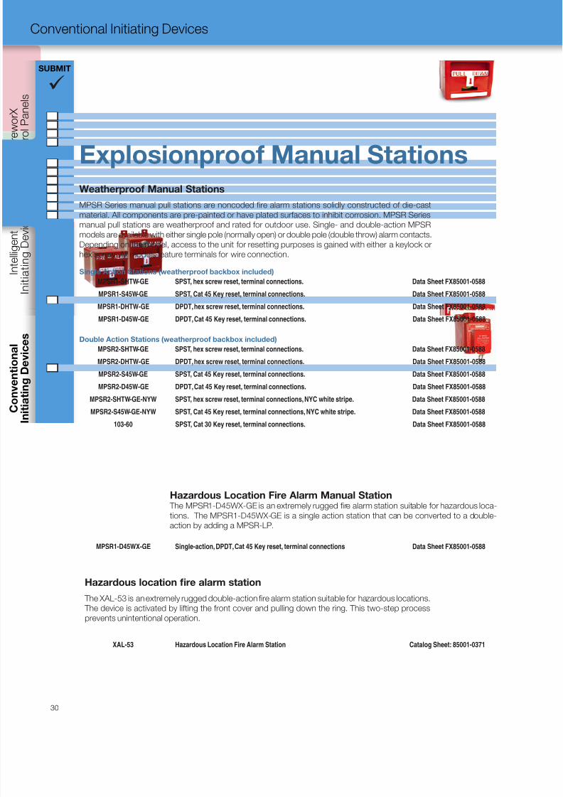
8/10/2019 FX85005-0132 -- FireworX Submittal Guide
http://slidepdf.com/reader/full/fx85005-0132-fireworx-submittal-guide 38/56
C o n t r
o l P a n e l s
I n i t i a t i n g D e v i c e s
I n
i t i a t i n g
D e v i c e s
SUBMIT
30
Conventional Initiating Devices
Weatherproof Manual Stations
MPSR Series manual pull stations are noncoded fire alarm stations solidly constructed of die-cast
material. All components are pre-painted or have plated surfaces to inhibit corrosion. MPSR Series
manual pull stations are weatherproof and rated for outdoor use. Single- and double-action MPSR
models are available with either single pole (normally open) or double pole (double throw) alarm contacts.
Depending on the model, access to the unit for resetting purposes is gained with either a keylock or
hex screw. All models feature terminals for wire connection.
Single Action Stations (weatherproof backbox included)
MPSR1-SHTW-GE SPST, hex screw reset, terminal connections. Data Sheet FX85001-0588
MPSR1-S45W-GE SPST, Cat 45 Key reset, terminal connections. Data Sheet FX85001-0588
MPSR1-DHTW-GE DPDT, hex screw reset, terminal connections. Data Sheet FX85001-0588
MPSR1-D45W-GE DPDT, Cat 45 Key reset, terminal connections. Data Sheet FX85001-0588
Double Action Stations (weatherproof backbox included)
MPSR2-SHTW-GE SPST, hex screw reset, terminal connections. Data Sheet FX85001-0588
MPSR2-DHTW-GE DPDT, hex screw reset, terminal connections. Data Sheet FX85001-0588
MPSR2-S45W-GE SPST, Cat 45 Key reset, terminal connections. Data Sheet FX85001-0588
MPSR2-D45W-GE DPDT, Cat 45 Key reset, terminal connections. Data Sheet FX85001-0588
MPSR2-SHTW-GE-NYW SPST, hex screw reset, terminal connections, NYC white stripe. Data Sheet FX85001-0588
MPSR2-S45W-GE-NYW SPST, Cat 45 Key reset, terminal connections, NYC white stripe. Data Sheet FX85001-0588
103-60 SPST, Cat 30 Key reset, terminal connections. Data Sheet FX85001-0588
Hazardous Location Fire Alarm Manual Station The MPSR1-D45WX-GE is an extremely rugged fire alarm station suitable for hazardous loca-
tions. The MPSR1-D45WX-GE is a single action station that can be converted to a double-
action by adding a MPSR-LP.
MPSR1-D45WX-GE Single-action, DPDT, Cat 45 Key reset, terminal connections Data Sheet FX85001-0588
Hazardous location fire alarm station
The XAL-53 is an extremely rugged double-action fire alarm station suitable for hazardous locations.
The device is activated by lifting the front cover and pulling down the ring. This two-step process
prevents unintentional operation.
XAL-53 Hazardous Location Fire Alarm Station Catalog Sheet: 85001-0371
Explosionproof Manual Stations
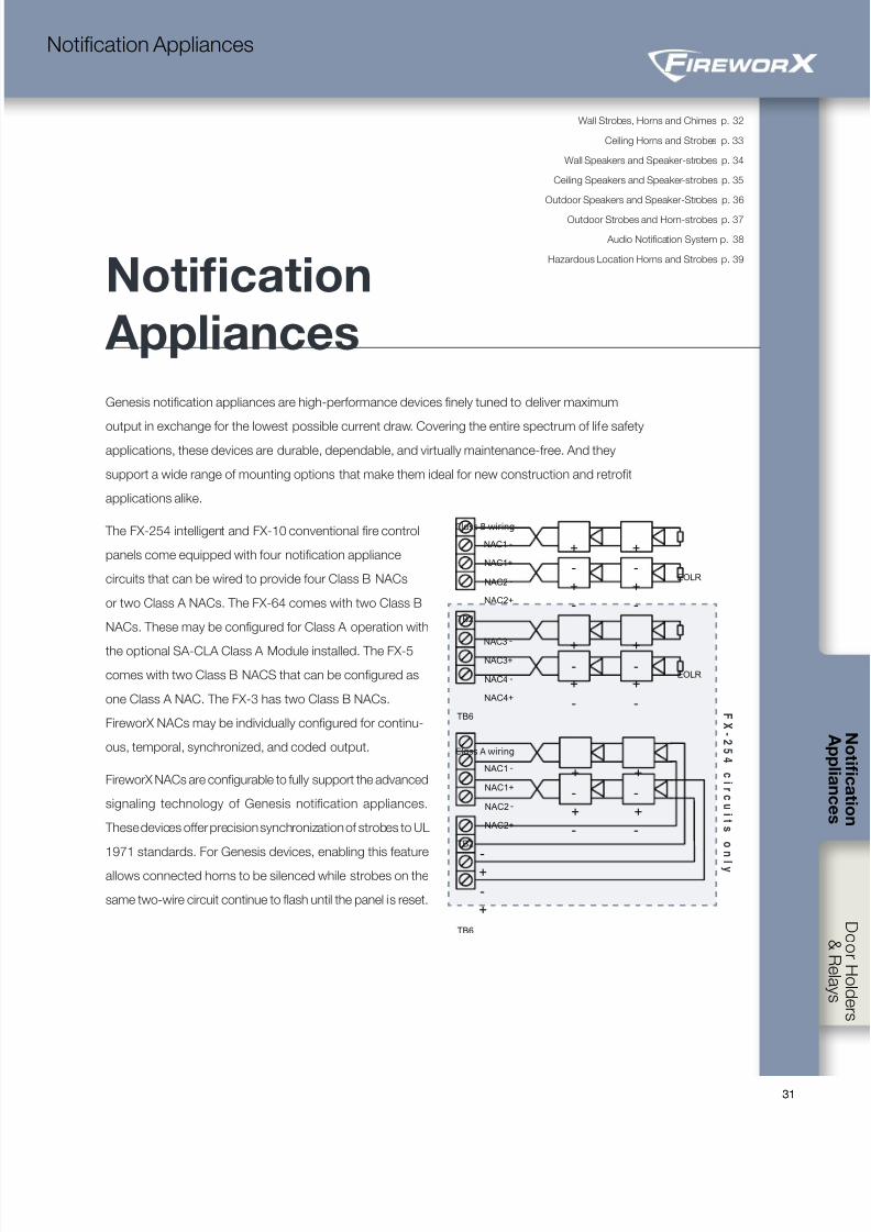
8/10/2019 FX85005-0132 -- FireworX Submittal Guide
http://slidepdf.com/reader/full/fx85005-0132-fireworx-submittal-guide 39/563131
Wall Strobes, Horns and Chimes p. 32
Ceiling Horns and Strobes p. 33
Wall Speakers and Speaker-strobes p. 34
Ceiling Speakers and Speaker-strobes p. 35
Outdoor Speakers and Speaker-Strobes p. 36
Outdoor Strobes and Horn-strobes p. 37
Audio Notification System p. 38
Hazardous Location Horns and Strobes p. 39
Notification Appliances
Notification
Appliances
Genesis notification appliances are high-performance devices finely tuned to deliver maximum
output in exchange for the lowest possible current draw. Covering the entire spectrum of life safetyapplications, these devices are durable, dependable, and virtually maintenance-free. And they
support a wide range of mounting options that make them ideal for new construction and retrofit
applications alike.
The FX-254 intelligent and FX-10 conventional fire control
panels come equipped with four notification appliance
circuits that can be wired to provide four Class B NACs
or two Class A NACs. The FX-64 comes with two Class B
NACs. These may be configured for Class A operation with
the optional SA-CLA Class A Module installed. The FX-5
comes with two Class B NACS that can be configured as
one Class A NAC. The FX-3 has two Class B NACs.
FireworX NACs may be individually configured for continu-
ous, temporal, synchronized, and coded output.
FireworX NACs are configurable to fully support the advanced
signaling technology of Genesis notification appliances.
These devices offer precision synchronization of strobes to UL
1971 standards. For Genesis devices, enabling this feature
allows connected horns to be silenced while strobes on the
same two-wire circuit continue to flash until the panel is reset.
TB6
NAC3 -
NAC4+
NAC4 -
NAC3+
EOLR
+ +
+ +
Class A wiring
TB2
TB6
NAC1 -
NAC2+
NAC2 -
NAC1+
+ +
+ +
+
+
- -
- -
- -
- -
-
-
Class B wiring
TB2
EOLR
NAC1 -
NAC2+
NAC2 -
NAC1+
+ +
+ +
- -
- -
F
X
- 2
5
4
c
i r c
u
i t s
o
n
l y
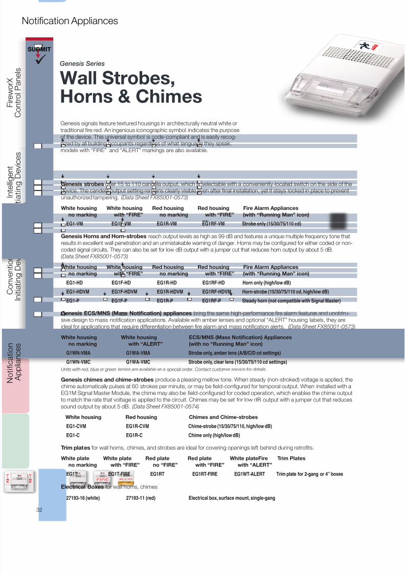
8/10/2019 FX85005-0132 -- FireworX Submittal Guide
http://slidepdf.com/reader/full/fx85005-0132-fireworx-submittal-guide 40/56
C o n t r
o l P a n e l s
I n i t i a t i n g D e v i c e s
I n i t i a t i n g D e v i c e s
A p p l i a n c e s
SUBMIT
32
Notification Appliances
Genesis Series
Wall Strobes,
Horns & ChimesGenesis signals feature textured housings in architecturally neutral white or
traditional fire red. An ingenious iconographic symbol indicates the purpose
of the device. This universal symbol is code-compliant and is easily recog-
nized by all building occupants regardless of what language they speak.
models with “FIRE” and “ALERT” markings are also available.
Genesis strobes offer 15 to 110 candela output, which is selectable with a conveniently-located switch on the side of the
device. The candela output setting remains clearly visible even after final installation, yet it stays locked in place to prevent
unauthorized tampering. (Data Sheet FX85001-0573)
White housing White housing Red housing Red housing Fire Alarm Appliances
no marking with “FIRE” no marking with “FIRE” (with “Running Man” icon)
EG1-VM EG1F-VM EG1R-VM EG1RF-VM Strobe only (15/30/75/110 cd)
Genesis Horns and Horn-strobes reach output levels as high as 99 dB and features a unique multiple frequency tone that
results in excellent wall penetration and an unmistakable warning of danger. Horns may be configured for either coded or non-
coded signal circuits. They can also be set for low dB output with a jumper cut that reduces horn output by about 5 dB.
(Data Sheet FX85001-0573)
White housing White housing Red housing Red housing Fire Alarm Appliances
no marking with “FIRE” no marking with “FIRE” (with “Running Man” icon)
EG1-HD EG1F-HD EG1R-HD EG1RF-HD Horn only (high/low dB)
EG1-HDVM EG1F-HDVM EG1R-HDVM EG1RF-HDVM Horn-strobe (15/30/75/110 cd, high/low dB)
EG1-P EG1F-P EG1R-P EG1RF-P Steady horn (not compatible with Signal Master)
Genesis ECS/MNS (Mass Notification) appliances bring the same high-performance fire alarm features and unobtru-
sive design to mass notification applications. Available with amber lenses and optional “ALERT” housing labels, they are
ideal for applications that require differentiation between fire alarm and mass notification alerts. (Data Sheet FX85001-0573)
White housing White housing ECS/MNS (Mass Notification) Appliances
no marking with “ALERT” (with no “Running Man” icon)
G1WN-VMA G1WA-VMA Strobe only, amber lens (A/B/C/D cd settings)
G1WN-VMC G1WA-VMC Strobe only, clear lens (15/30/75/110 cd settings)
Units with red, blue or green lenses are available as a special order. Contact customer service for details.
Genesis chimes and chime-strobes produce a pleasing mellow tone. When steady (non-stroked) voltage is applied, the
chime automatically pulses at 60 strokes per minute, or may be field-configured for temporal output. When installed with a
EG1M Signal Master Module, the chime may also be field-configured for coded operation, which enables the chime output
to match the rate that voltage is applied to the circuit. Chimes may be set for low dB output with a jumper cut that reducessound output by about 5 dB. (Data Sheet FX85001-0574)
White housing Red housing Chimes and Chime-strobes
EG1-CVM EG1R-CVM Chime-strobe (15/30/75/110, high/low dB)
EG1-C EG1R-C Chime only (high/low dB)
Trim plates for wall horns, chimes, and strobes are ideal for covering openings left behind during retrofits.
White plate White plate Red plate Red plate White plateFire Trim Plates
no marking with “FIRE” no “FIRE” with “FIRE” with “ALERT”
EG1T EG1T-FIRE EG1RT EG1RT-FIRE EG1WT-ALERT Trim plate for 2-gang or 4” boxes
Electrical Boxes for wall horns, chimes
27193-16 (white) 27193-11 (red) Electrical box, surface mount, single-gang
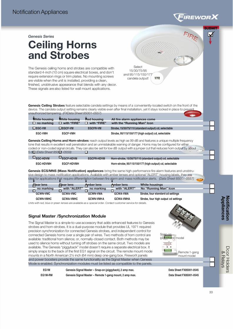
8/10/2019 FX85005-0132 -- FireworX Submittal Guide
http://slidepdf.com/reader/full/fx85005-0132-fireworx-submittal-guide 41/5633
SUBMIT
Notification Appliances
Signal Master /Synchronization Module
The Signal Master is a simple-to-use accessory that adds enhanced features to Genesis
strobes and horn-strobes. It is a dual-purpose module that provides UL 1971 required
precision synchronization for connected Genesis strobes, and independent control forconnected Genesis horns over a single pair of wires. Two methods of horn control are
available: traditional horn silence; or, normally-closed contact. Both methods may be
used to silence horns without turning off strobes on the same circuit. Two models are
available. The Genesis “piggyback” model doesn’t require a separate electrical box. It
simply snaps to the back of the first EG1 signal on the circuit. The remote mount model
mounts in a North American 2½ inch (64 mm) deep one-gang box. FireworX panels
and power boosters provide the same functionality as the Signal Master when Genesis
Mode is enabled. Synchronization modules must be listed as compatible to the panels.
EG1M Genesis Signal Master – Snap-on (piggyback), 2 amp max. Data Sheet FX85001-0545
EG1M-RM Genesis Signal Master – Remote 1-gang mount, 2 amp max. Data Sheet FX85001-0545
Snap-on
(piggyback) model
Remote 1-gang
mount model
Genesis Ceiling Strobes feature selectable candela settings by means of a conveniently-located switch on the front of the
device. The candela output setting remains clearly visible even after final installation, yet it stays locked in place to prevent
unauthorized tampering. (FXData Sheet 85001-0557)
White housing White housing Red housing All fire alarm appliances come
no marking with “FIRE” with “FIRE” with the “Running Man” Icon
EGC-VM EGCF-VM EGCFR-VM Strobe, 15/30/75/110 (standard output) cd, selectable
EGC-VMH EGCF-VMH Strobe, 95/115/150/177 (high output) cd, selectable
Genesis Ceiling Horns and Horn-strobes reach output levels as high as 99 dB and features a unique multiple frequency
tone that results in excellent wall penetration and an unmistakable warning of danger. Horns may be configured for either
coded or non-coded signal circuits. They can also be set for low dB output with a jumper cut that reduces horn output by about
5 dB. (Data Sheet 85001-0559)
EGC-HDVM EGCF-HDVM EGCFR-HDVM Horn-strobe, 15/30/75/110 (standard output) cd, selectable
EGC-HDVMH EGCF-HDVMH Horn-strobe, 95/115/150/177 (high output) cd, selectable
Genesis ECS/MNS (Mass Notification) appliances bring the same high-performance fire alarm features and unobtru-
sive design to mass notification applications. Available with amber lenses and optional “ALERT” housing labels, they are
ideal for applications that require differentiation between fire alarm and mass notification alerts. (Data Sheet 85001-0557)
Clear lens Clear lens Amber lens Amber lens White housings
no marking with “ALERT” no marking with “ALERT” No “Running Man” Icon
GCWN-VMC GCWA-VMC GCWN-VMA GCWA-VMA Strobe, four standard cd settings
GCWN-VMHC GCWA-VMHC GCWN-VMHA GCWA-VMHA Strobe, four high output cd settings
Units with red, blue or green lenses are available as a special order. Contact customer service for details.
The Genesis ceiling horns and strobes are compatible with
standard 4-inch (10 cm) square electrical boxes, and don’t
require extension rings or trim plates. No mounting screws
are visible when the unit is installed, providing a clean,
finished, unobtrusive appearance that blends with any decor.
These signals are also listed for wall mount applications.
Select
15/30/75/95
and 95/115/150/177
candela output!
Genesis Series
Ceiling Horns
and Strobes
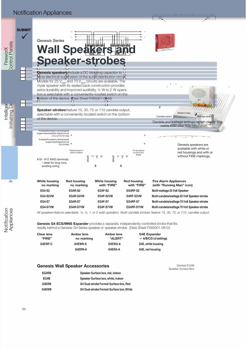
8/10/2019 FX85005-0132 -- FireworX Submittal Guide
http://slidepdf.com/reader/full/fx85005-0132-fireworx-submittal-guide 42/56
C o n t r
o l P a n e l s
I n i t i a t i n g D e v i c e s
I n i t i a t i n g D e v i c e s
A p p l i a n c e s
SUBMIT
34
Notification Appliances
Genesis EG4B
Speaker Surface BoxGenesis Wall Speaker Accessories
EG4RB Speaker Surface box, red, indoor
EG4B Speaker Surface box, white, indoor
G4ERB G4 Dual-strobe Format Surface box, Red
G4EWB G4 Dual-strobe Format Surface box, White
Genesis speakers include a DC blocking capacitor to
allow electrical supervision of the audio distribution circuit.
Models for 25 V RMS
and 70 V RMS
circuits are available. The
mylar speaker with its sealed back construction provides
extra durability and improved audibility. ¼ W to 2 W opera-
tion is selectable with a conveniently-located switch on the
bottom of the device. (Data Sheet FX85001-0549)
Speaker-strobes feature 15, 30, 75 or 110 candela output,
selectable with a conveniently-located switch on the bottom
of the device.
Genesis speakers are
available with white or
red housings and with or
without FIRE markings.
1
Bottom View
Wattage switch
1 5
Candela switch
il i
i i i
Candela and wattage settings remain clearlyvisible even after final installation.
Genesis Series
Wall Speakers and
Speaker-strobes
S P K R
S +
C S -
Polarity shown inalarm condition
To next deviceor end of line
device
++
S P K R
S +
C S -
S S
+ +
To listed fire alarm control panel(supervised signal circuit
– 20-24 Vdc)
To listed fire alarm control panel(supervised amplifier signal circuit
– 25.2 or 70.7V rms)
White housing Red housing White housing Red housing Fire Alarm Appliances
no marking no marking with “FIRE” with “FIRE” (with “Running Man” icon)
EG4-S2 EG4R-S2 EG4F-S2 EG4RF-S2 Multi-wattage 25 Volt Speaker
EG4-S2VM EG4R-S2VM EG4F-S2VM G4RF-S2VM Multi-candela/wattage 25 Volt Speaker-strobe
EG4-S7 EG4R-S7 EG4F-S7 EG4RF-S7 Multi-candela/wattage 70 Volt Speaker-strobe
EG4-S7VM EG4R-S7VM EG4F-S7VM EG4RF-S7VM Multi-candela/wattage 70 Volt Speaker-strobe
All speakers feature selectable ¼, ½, 1, or 2 watt operation. Multi-candela strobes feature 15, 30, 75, or 110 candela output.
Genesis G4 ECS/MNS Expander provides a separate, independently-controlled strobe that fits
readily behind a Genesis G4 Series speaker or speaker-strobe. (Data Sheet FX85001-0610)
Clear lens Amber lens Amber lens G4E Expander
“FIRE” no marking “ALERT” — A/B/C/D cd settings
G4EWF-C G4EWN-A G4EWA-A G4E, white housing
G4ERN-A G4ERA-A G4E, red housing
#18 - #12 AWG terminals
– ideal for long runs,
existing wiring
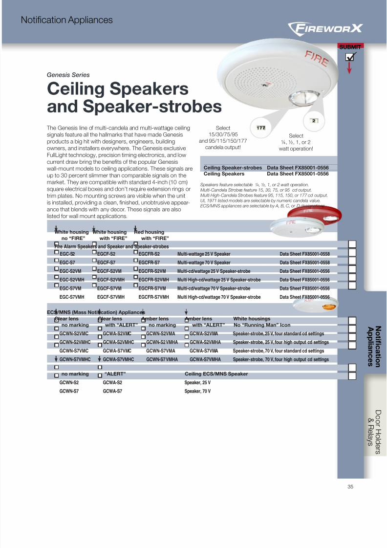
8/10/2019 FX85005-0132 -- FireworX Submittal Guide
http://slidepdf.com/reader/full/fx85005-0132-fireworx-submittal-guide 43/5635
SUBMIT
Notification Appliances
Select
¼, ½, 1, or 2
watt operation!
The Genesis line of multi-candela and multi-wattage ceiling
signals feature all the hallmarks that have made Genesis
products a big hit with designers, engineers, building
owners, and installers everywhere. The Genesis exclusive
FullLight technology, precision timing electronics, and low
current draw bring the benefits of the popular Genesis
wall-mount models to ceiling applications. These signals are
up to 30 percent slimmer than comparable signals on the
market. They are compatible with standard 4-inch (10 cm)
square electrical boxes and don’t require extension rings ortrim plates. No mounting screws are visible when the unit
is installed, providing a clean, finished, unobtrusive appear-
ance that blends with any decor. These signals are also
listed for wall mount applications.
White housing White housing Red housing
no “FIRE” with “FIRE” with “FIRE”
Fire Alarm Speakers and Speaker and Speaker-strobes
EGC-S2 EGCF-S2 EGCFR-S2 Multi-wattage 25 V Speaker Data Sheet FX85001-0558
EGC-S7 EGCF-S7 EGCFR-S7 Multi-wattage 70 V Speaker Data Sheet FX85001-0558
EGC-S2VM EGCF-S2VM EGCFR-S2VM Multi-cd/wattage 25 V Speaker-strobe Data Sheet FX85001-0556
EGC-S2VMH EGCF-S2VMH EGCFR-S2VMH Multi High-cd/wattage 25 V Speaker-strobe Data Sheet FX85001-0556
EGC-S7VM EGCF-S7VM EGCFR-S7VM Multi-cd/wattage 70 V Speaker-strobe Data Sheet FX85001-0556
EGC-S7VMH EGCF-S7VMH EGCFR-S7VMH Multi High-cd/wattage 70 V Speaker-strobe Data Sheet FX85001-0556
ECS/MNS (Mass Notification) Appliances
Clear lens Clear lens Amber lens Amber lens White housings
no marking with “ALERT” no marking with “ALERT” No “Running Man” Icon
GCWN-S2VMC GCWA-S2VMC GCWN-S2VMA GCWA-S2VMA Speaker-strobe, 25 V, four standard cd settings
GCWN-S2VMHC GCWA-S2VMHC GCWN-S2VMHA GCWA-S2VMHA Speaker-strobe, 25 V, four high output cd settings
GCWN-S7VMC GCWA-S7VMC GCWN-S7VMA GCWA-S7VMA Speaker-strobe, 70 V, four standard cd settings
GCWN-S7VMHC GCWA-S7VMHC GCWN-S7VMHA GCWA-S7VMHA Speaker-strobe, 70 V, four high output cd settings
no marking “ALERT” Ceiling ECS/MNS Speaker
GCWN-S2 GCWA-S2 Speaker, 25 VGCWN-S7 GCWA-S7 Speaker, 70 V
Select
15/30/75/95
and 95/115/150/177
candela output!
Genesis Series
Ceiling Speakersand Speaker-strobes
Ceiling Speaker-strobes Data Sheet FX85001-0556
Ceiling Speakers Data Sheet FX85001-0556
Speakers feature selectable ¼, ½, 1, or 2 watt operation.
Multi-Candela Strobes feature 15, 30, 75, or 95 cd output.Multi High-Candela Strobes feature 95, 115, 150, or 177 cd output.
UL 1971 listed models are selectable by numeric candela value.
ECS/MNS appliances are selectable by A, B, C, or D designations.

8/10/2019 FX85005-0132 -- FireworX Submittal Guide
http://slidepdf.com/reader/full/fx85005-0132-fireworx-submittal-guide 44/56
C o n t r
o l P a n e l s
I n i t i a t i n g D e v i c e s
I n i t i a t i n g D e v i c e s
A p p l i a n c e s
SUBMIT
36
Notification Appliances
Genesis Series
Outdoor Speakers
and Speaker-strobesGenesis WG4 Series speakers and speaker-strobes are among the most
versatile emergency signals of their kind. NEMA 4X rated for indoor or
outdoor use, they are suitable for a wide range of wet and harsh environ-
ments with a listed operating temperature range of as low as -31°F to as
high as 151°F (-35°C to 66°C).
Refer to Data Sheet 85001-0627 -- Genesis Outdoor Speakers and Strobes for details.
Field Configuration
S1:
wattage
S2:
CandelaJP1: Strobe temporal
mode selection
S3: Speakervoltage
SPKR -
SPKR +
STROBE -
STROBE +
SPKR -
SPKR +
STROBE -
STROBE +Genesis WG4 speakers may be set 70- or 25-Volt
operation, and for ¼, ½, 1, or 2 watt operation.
Strobe models feature four selectable light output
settings. Wattage and cd selections are changed
by removing the cover and simply sliding the
switches to the desired settings, which remain vis-
ible through a small window on the front of the de-
vice after the cover is replaced. Genesis speaker-
strobes may also be configured for temporal flash.
This battery-saving feature is intended for private
mode signaling only. To set the device for temporal
flash, snip the jumper at JP1.
WG4RF-S WG4RF-SVMC WG4WF-S WG4WF-SVMC WG4RN-S WG4RN-SVMC WG4WN-S WG4WN-SVMC WG4WN-SVMA WG4WA-SVMA WG4WA-SVMC
White housing White housing Red housing Red housing Fire Alarm Speakers
no marking with “FIRE” no marking with “FIRE”
WG4WN-S WG4WF-S WG4RN-S WG4RF-S 25/70 V Speaker
WG4WN-SVMC WG4WF-SVMC WG4RN-SVMC WG4RF-SVMC 25/70 V Speaker-strobe (15/29/70/87 cd)
WG4WF-SVMHC WG4RN-SVMHC WG4RF-SVMHC 25/70 V Speaker-strobe (102/123/147/161 cd)
Genesis ECS/MNS (Mass Notification) speakers and speaker-strobes bring the same high-performance fire alarm
features and unobtrusive design to mass notification applications. Available with amber lenses and optional “ALERT” lettering,
they are ideal for applications that require differentiation between fire alarm and mass notification alerts.
White housing White housing ECS/MNS (Mass Notification) Speakers
no marking “ALERT” — white housing, no “Running Man” icon
WG4WN-SVMA WG4WA-SVMA 25/70 V Speaker-strobe, amber lens (13/25/5962 cd output)
WG4WN-SVMHA WG4WA-SVMHA 25/70 V Speaker-strobe, amber lens (84/101/125/130 cd output)
WG4WA-SVMC 25/70 V Speaker-strobe, clear lens (15/29/70/87 cd output)
WG4WN-SVMHC WG4WA-SVMHC 25/70 V Speaker-strobe, clear lens (102/123/147/161 cd output)
WG4WA-S 25/70 V Speaker
Trim skirts
WG4WTS (white) WG4RTS (red) Surface Skirt for Genesis WG4 appliance family.
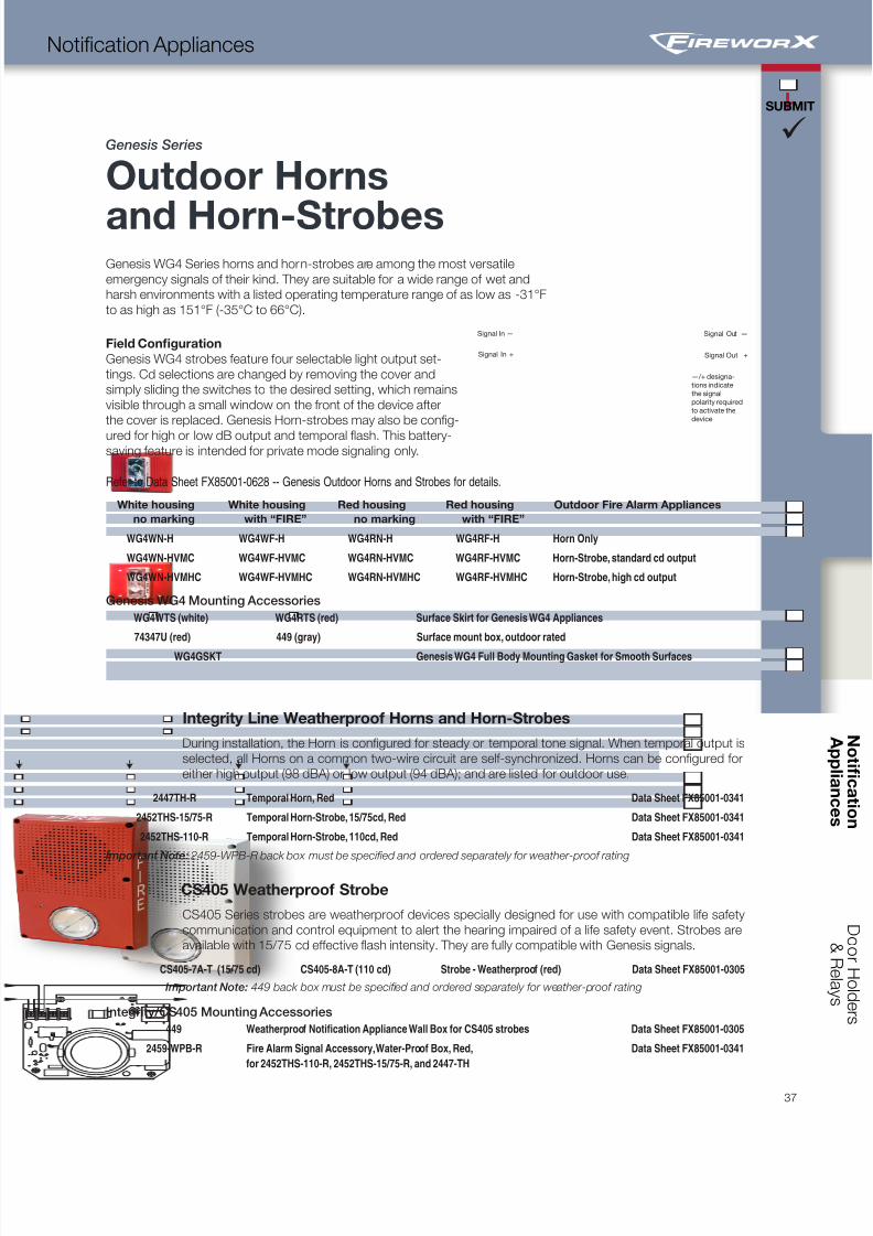
8/10/2019 FX85005-0132 -- FireworX Submittal Guide
http://slidepdf.com/reader/full/fx85005-0132-fireworx-submittal-guide 45/5637
SUBMIT
Notification Appliances
Integrity Line Weatherproof Horns and Horn-Strobes
During installation, the Horn is configured for steady or temporal tone signal. When temporal output is
selected, all Horns on a common two-wire circuit are self-synchronized. Horns can be configured for
either high output (98 dBA) or low output (94 dBA); and are listed for outdoor use.
2447TH-R Temporal Horn, Red Data Sheet FX85001-0341
2452THS-15/75-R Temporal Horn-Strobe, 15/75cd, Red Data Sheet FX85001-0341
2452THS-110-R Temporal Horn-Strobe, 110cd, Red Data Sheet FX85001-0341
Important Note: 2459-WPB-R back box must be specified and ordered separately for weather-proof rating
CS405 Weatherproof Strobe
CS405 Series strobes are weatherproof devices specially designed for use with compatible life safety
communication and control equipment to alert the hearing impaired of a life safety event. Strobes are
available with 15/75 cd effective flash intensity. They are fully compatible with Genesis signals.
CS405-7A-T (15/75 cd) CS405-8A-T (110 cd) Strobe - Weatherproof (red) Data Sheet FX85001-0305
Important Note: 449 back box must be specified and ordered separately for weather-proof rating
Integrity/CS405 Mounting Accessories
449 Weatherproof Notification Appliance Wall Box for CS405 strobes Data Sheet FX85001-0305
2459-WPB-R Fire Alarm Signal Accessory, Water-Proof Box, Red, Data Sheet FX85001-0341
for 2452THS-110-R, 2452THS-15/75-R, and 2447-TH
Genesis Series
Outdoor Horns
and Horn-StrobesGenesis WG4 Series horns and horn-strobes are among the most versatile
emergency signals of their kind. They are suitable for a wide range of wet and
harsh environments with a listed operating temperature range of as low as -31°F
to as high as 151°F (-35°C to 66°C).
Field Configuration
Genesis WG4 strobes feature four selectable light output set-
tings. Cd selections are changed by removing the cover and
simply sliding the switches to the desired setting, which remains
visible through a small window on the front of the device after
the cover is replaced. Genesis Horn-strobes may also be config-
ured for high or low dB output and temporal flash. This battery-saving feature is intended for private mode signaling only.
Refer to Data Sheet FX85001-0628 -- Genesis Outdoor Horns and Strobes for details.
White housing White housing Red housing Red housing Outdoor Fire Alarm Appliances
no marking with “FIRE” no marking with “FIRE”
WG4WN-H WG4WF-H WG4RN-H WG4RF-H Horn Only
WG4WN-HVMC WG4WF-HVMC WG4RN-HVMC WG4RF-HVMC Horn-Strobe, standard cd output
WG4WN-HVMHC WG4WF-HVMHC WG4RN-HVMHC WG4RF-HVMHC Horn-Strobe, high cd output
Genesis WG4 Mounting Accessories
WG4WTS (white) WG4RTS (red) Surface Skirt for Genesis WG4 Appliances
74347U (red) 449 (gray) Surface mount box, outdoor rated
WG4GSKT Genesis WG4 Full Body Mounting Gasket for Smooth Surfaces
Signal In —
Signal In +
Signal Out —
Signal Out +
—/+ designa-
tions indicate
the signal
polarity required
to activate the
device.
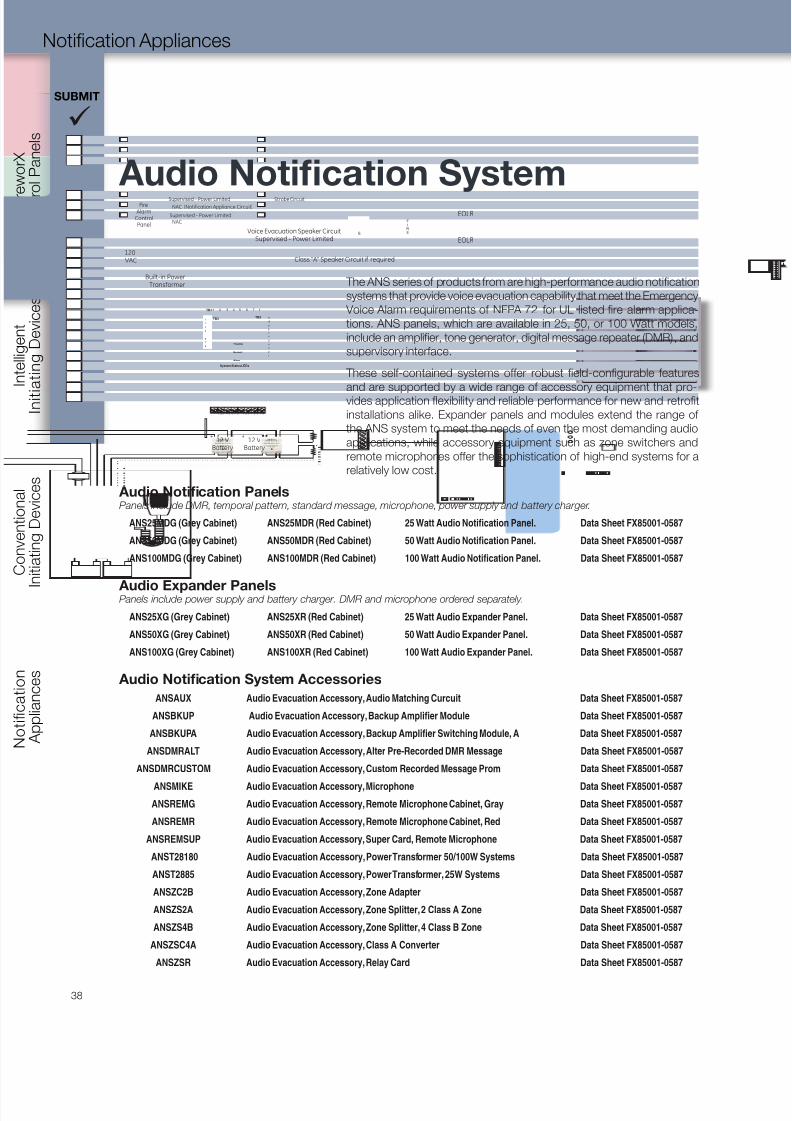
8/10/2019 FX85005-0132 -- FireworX Submittal Guide
http://slidepdf.com/reader/full/fx85005-0132-fireworx-submittal-guide 46/56
C o n t r
o l P a n e l s
I n i t i a t i n g D e v i c e s
I n i t i a t i n g D e v i c e s
A p p l i a n c e s
SUBMIT
38
Notification Appliances
Audio Notification PanelsPanels include DMR, temporal pattern, standard message, microphone, power supply and battery charger.
ANS25MDG (Grey Cabinet) ANS25MDR (Red Cabinet) 25 Watt Audio Notification Panel. Data Sheet FX85001-0587
ANS50MDG (Grey Cabinet) ANS50MDR (Red Cabinet) 50 Watt Audio Notification Panel. Data Sheet FX85001-0587
ANS100MDG (Grey Cabinet) ANS100MDR (Red Cabinet) 100 Watt Audio Notification Panel. Data Sheet FX85001-0587
Audio Expander PanelsPanels include power supply and battery charger. DMR and microphone ordered separately.
ANS25XG (Grey Cabinet) ANS25XR (Red Cabinet) 25 Watt Audio Expander Panel. Data Sheet FX85001-0587
ANS50XG (Grey Cabinet) ANS50XR (Red Cabinet) 50 Watt Audio Expander Panel. Data Sheet FX85001-0587
ANS100XG (Grey Cabinet) ANS100XR (Red Cabinet) 100 Watt Audio Expander Panel. Data Sheet FX85001-0587
Audio Notification System Accessories
ANSAUX Audio Evacuation Accessory, Audio Matching Curcuit Data Sheet FX85001-0587
ANSBKUP Audio Evacuation Accessory, Backup Amplifier Module Data Sheet FX85001-0587
ANSBKUPA Audio Evacuation Accessory, Backup Amplifier Switching Module, A Data Sheet FX85001-0587
ANSDMRALT Audio Evacuation Accessory, Alter Pre-Recorded DMR Message Data Sheet FX85001-0587
ANSDMRCUSTOM Audio Evacuation Accessory, Custom Recorded Message Prom Data Sheet FX85001-0587
ANSMIKE Audio Evacuation Accessory, Microphone Data Sheet FX85001-0587
ANSREMG Audio Evacuation Accessory, Remote Microphone Cabinet, Gray Data Sheet FX85001-0587
ANSREMR Audio Evacuation Accessory, Remote Microphone Cabinet, Red Data Sheet FX85001-0587
ANSREMSUP Audio Evacuation Accessory, Super Card, Remote Microphone Data Sheet FX85001-0587
ANST28180 Audio Evacuation Accessory, Power Transformer 50/100W Systems Data Sheet FX85001-0587
ANST2885 Audio Evacuation Accessory, Power Transformer, 25W Systems Data Sheet FX85001-0587
ANSZC2B Audio Evacuation Accessory, Zone Adapter Data Sheet FX85001-0587
ANSZS2A Audio Evacuation Accessory, Zone Splitter, 2 Class A Zone Data Sheet FX85001-0587
ANSZS4B Audio Evacuation Accessory, Zone Splitter, 4 Class B Zone Data Sheet FX85001-0587
ANSZSC4A Audio Evacuation Accessory, Class A Converter Data Sheet FX85001-0587
ANSZSR Audio Evacuation Accessory, Relay Card Data Sheet FX85001-0587
The ANS series of products from are high-performance audio notification
systems that provide voice evacuation capability that meet the Emergency
Voice Alarm requirements of NFPA 72 for UL listed fire alarm applica-
tions. ANS panels, which are available in 25, 50, or 100 Watt models,
include an amplifier, tone generator, digital message repeater (DMR), and
supervisory interface.
These self-contained systems offer robust field-configurable features
and are supported by a wide range of accessory equipment that pro-vides application flexibility and reliable performance for new and retrofit
installations alike. Expander panels and modules extend the range of
the ANS system to meet the needs of even the most demanding audio
applications, while accessory equipment such as zone switchers and
remote microphones offer the sophistication of high-end systems for a
relatively low cost.
NAC (Notification Appliance Circuit)
TB1
TB3 TB2
5
1
2
3
4
6
7
8
1
2
3
4
5
6
7
8
9
10
11
2 3 4 5 6 7 81 2 3 4 5 6 7 81
1 2 3 4 5 6 7 8
Normal
Alarm
Trouble
System Status LEDs
FireAlarm
ControlPanel
F
I
R
E
F
I
R
E
EOLR
Voice Evacuation Speaker CircuitSupervised - Power Limited
Supervised - Power Limited
Supervised - Power Limited
EOLR
120VAC
Strobe Circuit
NAC
Class “A” Speaker Circuit if required
Built-in PowerTransformer
12 VBattery
+ - + -12 V
Battery
Audio Notification System
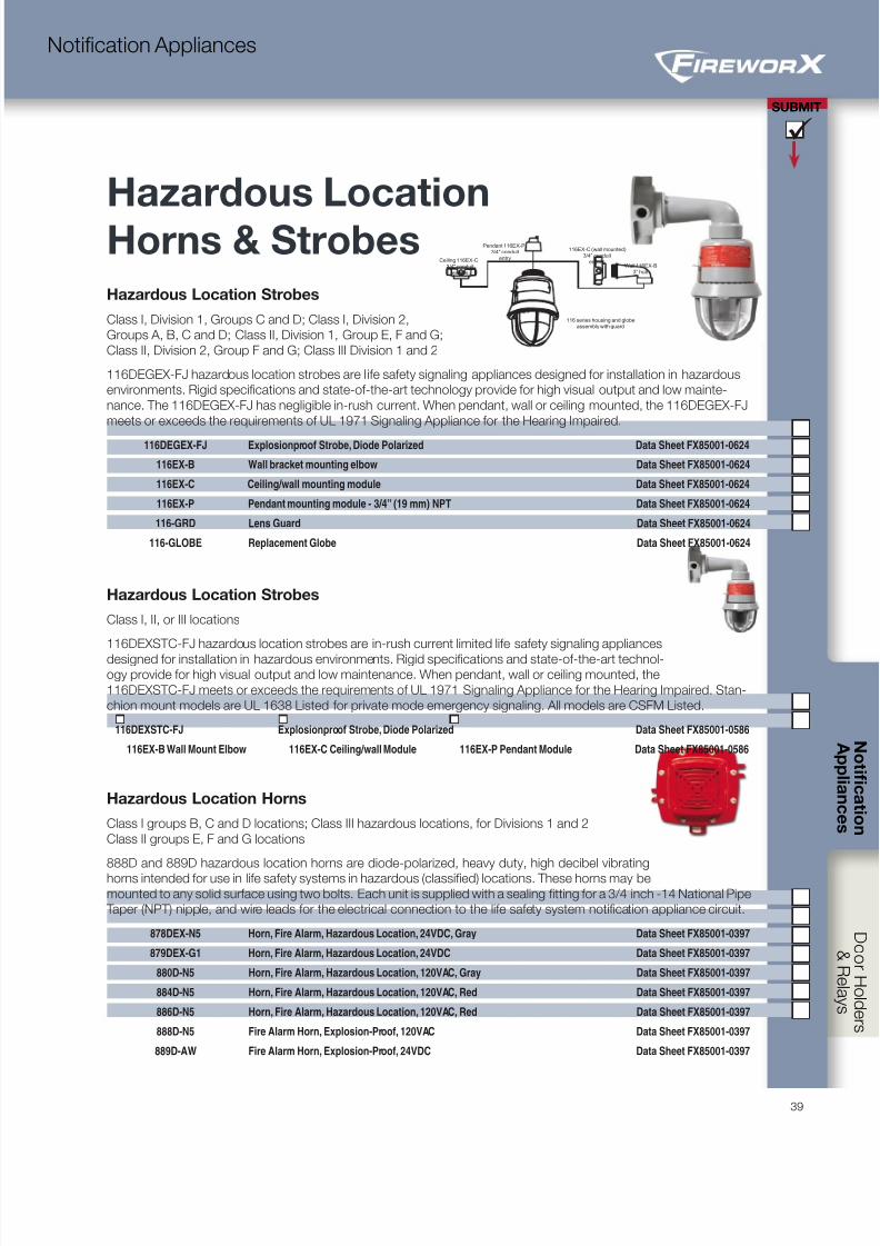
8/10/2019 FX85005-0132 -- FireworX Submittal Guide
http://slidepdf.com/reader/full/fx85005-0132-fireworx-submittal-guide 47/5639
SUBMIT
Notification Appliances
Hazardous Location Strobes
Class I, Division 1, Groups C and D; Class I, Division 2,
Groups A, B, C and D; Class II, Division 1, Group E, F and G;
Class II, Division 2, Group F and G; Class III Division 1 and 2
116DEGEX-FJ hazardous location strobes are l ife safety signaling appliances designed for installation in hazardous
environments. Rigid specifications and state-of-the-art technology provide for high visual output and low mainte-
nance. The 116DEGEX-FJ has negligible in-rush current. When pendant, wall or ceiling mounted, the 116DEGEX-FJ
meets or exceeds the requirements of UL 1971 Signaling Appliance for the Hearing Impaired.
116DEGEX-FJ Explosionproof Strobe, Diode Polarized Data Sheet FX85001-0624
116EX-B Wall bracket mounting elbow Data Sheet FX85001-0624
116EX-C Ceiling/wall mounting module Data Sheet FX85001-0624
116EX-P Pendant mounting module - 3/4” (19 mm) NPT Data Sheet FX85001-0624
116-GRD Lens Guard Data Sheet FX85001-0624
116-GLOBE Replacement Globe Data Sheet FX85001-0624
Hazardous Location Strobes
Class I, II, or III locations
116DEXSTC-FJ hazardous location strobes are in-rush current limited life safety signaling appliances
designed for installation in hazardous environments. Rigid specifications and state-of-the-art technol-ogy provide for high visual output and low maintenance. When pendant, wall or ceiling mounted, the
116DEXSTC-FJ meets or exceeds the requirements of UL 1971 Signaling Appliance for the Hearing Impaired. Stan-
chion mount models are UL 1638 Listed for private mode emergency signaling. All models are CSFM Listed.
116DEXSTC-FJ Explosionproof Strobe, Diode Polarized Data Sheet FX85001-0586
116EX-B Wall Mount Elbow 116EX-C Ceiling/wall Module 116EX-P Pendant Module Data Sheet FX85001-0586
Hazardous Location Horns
Class I groups B, C and D locations; Class III hazardous locations, for Divisions 1 and 2
Class II groups E, F and G locations
888D and 889D hazardous location horns are diode-polarized, heavy duty, high decibel vibrating
horns intended for use in life safety systems in hazardous (classified) locations. These horns may be
mounted to any solid surface using two bolts. Each unit is supplied with a sealing fitting for a 3/4 inch -14 National Pipe
Taper (NPT) nipple, and wire leads for the electrical connection to the life safety system notification appliance circuit.
878DEX-N5 Horn, Fire Alarm, Hazardous Location, 24VDC, Gray Data Sheet FX85001-0397
879DEX-G1 Horn, Fire Alarm, Hazardous Location, 24VDC Data Sheet FX85001-0397
880D-N5 Horn, Fire Alarm, Hazardous Location, 120VAC, Gray Data Sheet FX85001-0397
884D-N5 Horn, Fire Alarm, Hazardous Location, 120VAC, Red Data Sheet FX85001-0397
886D-N5 Horn, Fire Alarm, Hazardous Location, 120VAC, Red Data Sheet FX85001-0397
888D-N5 Fire Alarm Horn, Explosion-Proof, 120VAC Data Sheet FX85001-0397
889D-AW Fire Alarm Horn, Explosion-Proof, 24VDC Data Sheet FX85001-0397
Hazardous Location
Horns & StrobesCeiling 116EX-C
3/4" conduit
entries
Pendant 116EX-P3/4" conduit
entry
116EX-C (wall mounted)3/4” conduit
entries
116 series housing and globeassembly with guard
Wall 116EX-B3” hub
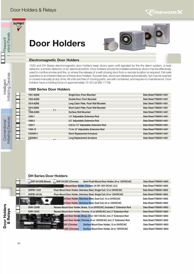
8/10/2019 FX85005-0132 -- FireworX Submittal Guide
http://slidepdf.com/reader/full/fx85005-0132-fireworx-submittal-guide 48/56
C o n t r
o l P a n e l s
I n i t i a t i n g D e v i c e s
I n i t i a t i n g D e v i c e s
A p p l i a n c e s
40
D o o r H o l d e r s & R e l a y s
SUBMIT
&
R e l a y s
Door Holders & Relays
Door HoldersElectromagnetic Door Holders
1500 and DH Series electromagnetic door holders keep doors open until signaled by the fire alarm system, a heat
detector, a smoke detector, or an electrical switch. Door holders should be installed wherever doors may be effectively
used to confine smoke and fire, or where the release of a self-closing door from a remote location is required. Fail-safe
operation is an inherent feature of these door holders. If power fails, doors are released automatically, but may be opened
or closed manually at any time. All units are free of moving parts, are self-contained, and require no maintenance. Door
holders have a holding force of approximately 15-25 Lbf (66-111N).
1500 Series Door Holders
1501-AQN5 Single Door, Floor Mounted Data Sheet FX85001-0421 1502-AQN5 Double Door, Floor Mounted Data Sheet FX85001-0421
1504-AQN5 Long Catch Plate, Flush Wall Mounted Data Sheet FX85001-0421
1505-AQN5 Short Catch Plate, Flush Wall Mounted Data Sheet FX85001-0421
1508-AQN5 Surface, Wall Mounted Data Sheet FX85001-0421
1500-1 1.5” Adjustable, Extension Rod Data Sheet FX85001-0421
1500-2 2.5” Adjustable, Extension Rod Data Sheet FX85001-0421
1500-7 5.25 to 7.5” Adjustable, Extension Rod Data Sheet FX85001-0421
1500-12 7.5 to 12” Adjustable, Extension Rod Data Sheet FX85001-0421
CS2595-5 Short Replacement Armature Data Sheet FX85001-0421
CS2598-5 Long Replacement Armature Data Sheet FX85001-0421
DH Series Door Holders
DHF-24120B (Brass) DHF-24120C (Chrome) Semi-Flush Mount Door Holder, 24 or 120VDC/AC Data Sheet FX85001-0603
DHF-24120CC Semi-Flush Mount Door Holder, Chrome, 24 OR 120V DC/AC, ULC Data Sheet FX85001-0603
DHFM1-1224 Floor Mount Door Holder, Stainless Steel, Single Coil, 12 or 24VDC/AC Data Sheet FX85001-0603
DHFM1-24120 Floor Mount Door Holder, Stainless Steel, Single Coil, 24 or 120VDC/AC Data Sheet FX85001-0603
DHFM2-1224 Floor Mount Door Holder, Stainless Steel, Dual Coil, 12 or 24VDC/AC Data Sheet FX85001-0603
DHFM2-24120 Floor Mount Door Holder, Stainless Steel, Dual Coil, 24 or 120VDC/AC Data Sheet FX85001-0603
DHR-1224B Recess Mount Door Holder, Brass, 12 or 24VDC/AC, Includes 3” Extension Rod Data Sheet FX85001-0603
DHR-1224C Recess Mount Door Holder, Chrome, 12 or 24VDC/AC, Incl. 3” Extension Rod Data Sheet FX85001-0603
DHR-24120B Recess Mount Door Holder, Brass, 24 or 120 V DC/AC, Incl. 3” Extension Rod Data Sheet FX85001-0603
DHR-24120C Recess Mount Door Holder, Chrome, 24 or 120VDC/AC, Incl. 3” Extension Rod Data Sheet FX85001-0603
DHS-1224B (Brass) DHS-1224C (Chrome) Surface Mount Door Holder, 12 or 24VDC/AC Data Sheet FX85001-0603
DHS-24120B (Brass) DHS-24120C (Chrome) Surface Mount Door Holder, 24 or 120VDC/AC Data Sheet FX85001-0603
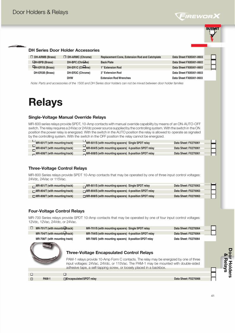
8/10/2019 FX85005-0132 -- FireworX Submittal Guide
http://slidepdf.com/reader/full/fx85005-0132-fireworx-submittal-guide 49/5641
SUBMIT
D o o r H o l d e r s & R e l a y s
SUBMIT
Door Holders & Relays
Relays
Single-Voltage Manual Override Relays
MR-600 series relays provide SPDT, 10-Amp contacts with manual override capability by means of an ON-AUTO-OFF
switch. The relay requires a 24Vac or 24Vdc power source supplied by the controlling system. With the switch in the ON
position the power relay is energized. With the switch in the AUTO position the relay is allowed to operate as signaled
by the controlling system. With the switch in the OFF position the relay cannot be energized.
MR-601/T (with mounting track) MR-601/S (with mounting spacers) Single SPDT relay Data Sheet: FX270061
MR-604/T (with mounting track) MR-604/S (with mounting spacers) 4-position SPDT relay Data Sheet: FX270061
MR-608/T (with mounting track) MR-608/S (with mounting spacers) 8-position SPDT relay Data Sheet: FX270061
Three-Voltage Control Relays
MR-800 Series relays provide SPDT 10-Amp contacts that may be operated by one of three input control voltages:24Vdc, 24Vac or 115Vac.
MR-801/T (with mounting track) MR-801/S (with mounting spacers) Single SPDT relay Data Sheet: FX270063
MR-804/T (with mounting track) MR-804/S (with mounting spacers) 4-position SPDT relay Data Sheet: FX270063
MR-808/T (with mounting track) MR-808/S (with mounting spacers) 8-position SPDT relay Data Sheet: FX270063
Four-Voltage Control Relays
MR-700 Series relays provide SPDT 10-Amp contacts that may be operated by one of four input control voltages:
12Vdc, 12Vac, 24Vdc, or 24Vac.
MR-701/T (with mounting track) MR-701/S (with mounting spacers) Single SPDT relay Data Sheet: FX270064
MR-704/T (with mounting track) MR-704/S (with mounting spacers) 4-position SPDT relay Data Sheet: FX270064
MR-708/T (with mounting track) MR-708/S (with mounting spacers) 8-position SPDT relay Data Sheet: FX270064
Three-Voltage Encapsulated Control Relays
PAM-1 relays provide 10-Amp Form C contacts. The relay may be energized by one of three
input voltages: 24Vac, 24Vdc, or 115Vac. The PAM-1 may be mounted with double-sided
adhesive tape, a self-tapping screw, or loosely placed in a backbox.
PAM-1 Encapsulated SPDT relay Data Sheet: FX270066
DH Series Door Holder Accessories
DH-ARMB (Brass) DH-ARMC (Chrome) Replacement Cone, Extension Rod and Catchplate Data Sheet FX85001-0603DH-BPB (Brass) DH-BPC (Chrome) Back Plate Data Sheet FX85001-0603
DH-ER1B (Brass) DH-ER1C (Chrome) 1” Extension Rod Data Sheet FX85001-0603
DH-ER3B (Brass) DH-ER3C (Chrome) 3” Extension Rod Data Sheet FX85001-0603
DHW Extension Rod Wrenches Data Sheet FX85001-0603
Note: Parts and accessories of the 1500 and DH Series door holders can not be mixed between door holder families
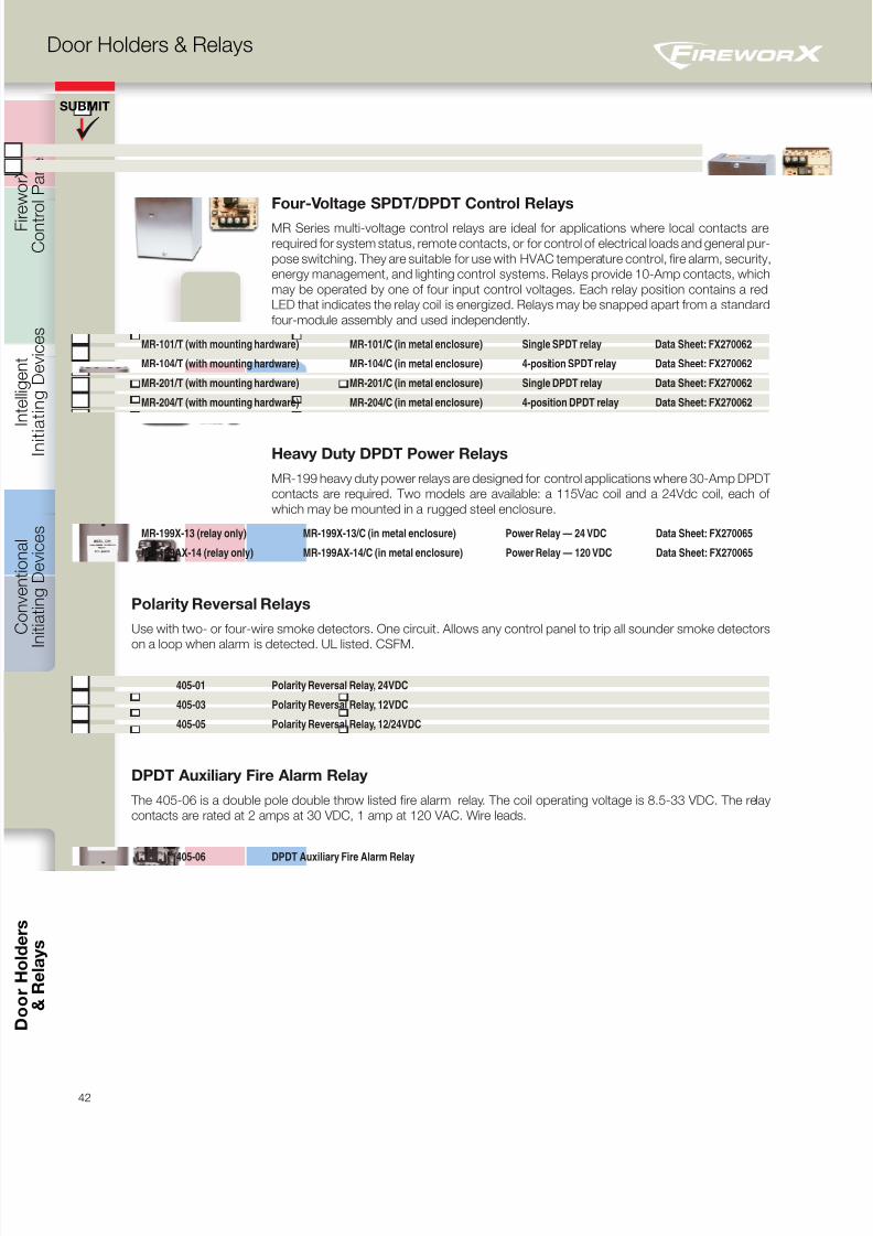
8/10/2019 FX85005-0132 -- FireworX Submittal Guide
http://slidepdf.com/reader/full/fx85005-0132-fireworx-submittal-guide 50/56
C o n t r
o l P a n e l s
I n i t i a t i n g D e v i c e s
I n i t i a t i n g D e v i c e s
A p p l i a n c e s
42
D o o r H o l d e r s & R e l a y s
SUBMIT
&
R e l a y s
Door Holders & Relays
Four-Voltage SPDT/DPDT Control Relays
MR Series multi-voltage control relays are ideal for applications where local contacts are
required for system status, remote contacts, or for control of electrical loads and general pur-
pose switching. They are suitable for use with HVAC temperature control, fire alarm, security,
energy management, and lighting control systems. Relays provide 10-Amp contacts, which
may be operated by one of four input control voltages. Each relay position contains a red
LED that indicates the relay coil is energized. Relays may be snapped apart from a standard
four-module assembly and used independently.
MR-101/T (with mounting hardware) MR-101/C (in metal enclosure) Single SPDT relay Data Sheet: FX270062
MR-104/T (with mounting hardware) MR-104/C (in metal enclosure) 4-position SPDT relay Data Sheet: FX270062
MR-201/T (with mounting hardware) MR-201/C (in metal enclosure) Single DPDT relay Data Sheet: FX270062
MR-204/T (with mounting hardware) MR-204/C (in metal enclosure) 4-position DPDT relay Data Sheet: FX270062
Heavy Duty DPDT Power Relays
MR-199 heavy duty power relays are designed for control applications where 30-Amp DPDT
contacts are required. Two models are available: a 115Vac coil and a 24Vdc coil, each of
which may be mounted in a rugged steel enclosure.
MR-199X-13 (relay only) MR-199X-13/C (in metal enclosure) Power Relay — 24 VDC Data Sheet: FX270065
MR-199AX-14 (relay only) MR-199AX-14/C (in metal enclosure) Power Relay — 120 VDC Data Sheet: FX270065
Polarity Reversal Relays
Use with two- or four-wire smoke detectors. One circuit. Allows any control panel to trip all sounder smoke detectors
on a loop when alarm is detected. UL listed. CSFM.
405-01 Polarity Reversal Relay, 24VDC
405-03 Polarity Reversal Relay, 12VDC
405-05 Polarity Reversal Relay, 12/24VDC
DPDT Auxiliary Fire Alarm Relay
The 405-06 is a double pole double throw listed fire alarm relay. The coil operating voltage is 8.5-33 VDC. The relay
contacts are rated at 2 amps at 30 VDC, 1 amp at 120 VAC. Wire leads.
405-06 DPDT Auxiliary Fire Alarm Relay
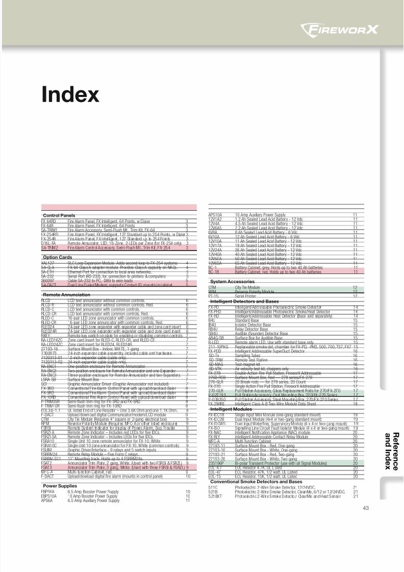
8/10/2019 FX85005-0132 -- FireworX Submittal Guide
http://slidepdf.com/reader/full/fx85005-0132-fireworx-submittal-guide 51/5643
Index
Control Panels
FX-64RD Fire Alarm Panel, FX Intelligent, 64 Points, w Dialer 3FX-64R Fire Alarm Panel, FX Intelligent, 64 Points 3SA-TRIM1 Fire Alarm Accessory, Semi-Flush Mt., Trim Kit, FX-64 3FX-254RD Fire Alarm Panel, FX Intelligent, 127 Standard up to 254 Points, w Dialer 3FX-254R Fire A larm Panel, FX I ntel li gent , 127 Standard up to 254 Po in ts 3D16L-FA Remote Annuciator, LED, 16-Zone, 2-LEDs per Zone (for FX-254 only) 3SA-TRIM2 Fire Alarm Control Accessory, Semi-Flush Mt., Trim Kit, FX-254 3
Option Cards
XAL127 SLC Loop Expansion Module. Adds second loop to FX-254 systems 4SA-CLA FX-64 Class A adapter module. Provides Class A capaci ty on NACs. 4SA-ETH Ethernet Port for connection to local area networks. 5SA-232 Serial Port (RS-232), for connection to printers & computers 5260097 Cable SA-232 to PC, DB9 to wire leads 5SA-DACT Dual Line Dialer/Modem, supports Contact ID, mounts in cabinet 5
Remote Annunciation
RLCD LCD text annunciator without common controls. 6RLCD-R LCD text annunciator without common controls. Red. 6RLCD-C LCD text annunciator with common controls. 6RLCD-CR LCD text annunciator with common controls. Red. 6RLED-C 16-pair LED zone annunciator with common controls. 6RLED-CR 16-pair LED zone annunciator with common controls. Red. 6RLED24 24-pair LED zone expander with expander cable and zone card insert. 6RLED24R 24-pair LED zone expander with expander cable and zone card insert 6RKEY Remote key switch on plate for enabling or disabling common controls 7RA-LED16ZC Zone card insert for RLED-C, RLED-CR, and RLED-CF. 7RA-LED24ZC Zone card insert for RLED24, RLED24R. 727193-16 Surface Mount Box - Indoor, WHITE, 1-gang 77300073 24-inch expander cable assembly, includes cable and hardware. 77120313-01 12-inch expander cable (cable only). 77120313-02 24-inch expander cable (cable only). 7RA-ENC1 One-position enclosure for Remote Annunciator. 7RA-ENC2 Two-posi tion enclosure for Remote Annunciator and one Expander. 7RA-ENC3 Three-position enclosure for Remote Annunciator and two Expanders. 7LSRA-SB Surface Mount Box 7GCI Graphic Annunciator Driver (Graphic Annunciator not included) 7FX-3RD Conventional Fire Alarm Control Panel wi th upload/download dialer 8FX-5RD Conventional Fire Alarm Control Panel wi th upload/download dialer 8FX-10RD Conventional Fi re Alarm Control Panel wi th upload/download dialer 8
F-TRIM35R Semi-flush trim ring for FX-3RD and FX-5RD 8F-TRIM10R Semi-flush trim ring for FX-10RD 8EOL3.6-1.1 UL listed End of Line Resistor – One 3.6K Ohm and one 1.1K Ohm. 8F-DACT Upload/download digital Communicator/modem/LCD module 9CTM City Tie Module (Requires 4” square or 2-gang electrical box) 9RPM Reverse Polar ity Modu le (Requ ires MFC-A or o ther li sted enclosure) 9FSRSI Remote System Indicator fo r d isplay of Power, A la rm, Sup, Trouble 9FSRZI-A Remote Zone Indicator – Includes red LEDs for five IDCs. 9FSRZI-SA Remote Zone Indicator – Includes LEDs for five IDCs. 9FSRA10 Single Unit 10 zone remote annunciator for FX-10, White 9FSRA10C Single Unit 10 zone annunciator for FX-10, White (common controls) 9FSUIM Graphic Driver/Interface - 9 relays and 5 switch inputs 9FSRRM24 Remote Relay Module – Five Form C relays. 9FSRRM-S11 11” Mounting track. Holds up to 4 FSRRM24s. 9FSAT2 Annunciator Trim Plate, 2 gang, White. (Used with two FSRSI & FSRZI.) 9FSAT3 Annunciator Trim Plate, 3 gang, White. (Used with three FSRSI & FSRZI.) 9MFC-A Mult i- functi on Cab inet , red . 9F-DACT Upload/dowload digital fire alarm (mounts in control panel) 10
Power Supplies
EBPS6A 6.5 Amp Booster Power Supply 10EBPS10A 10 Amp Booster Power Supply 10
APS6A 6.5 Amp Auxiliary Power Supply 11
APS10A 10 Amp Auxiliary Power Supply 1112V1A2 1.2 Ah Sealed Lead Acid Battery - 12 Vdc 1112V4A 4.5 Ah Sealed Lead Acid Battery - 12 Vdc 1112V6A5 7.2 Ah Sealed Lead Acid Battery - 12 Vdc 116V8A 8 Ah Sealed Lead Acid Battery - 6 Vdc 116V10A 12 Ah Sealed Lead Acid Battery - 6 Vdc 1112V10A 11 Ah Sealed Lead Acid Battery - 12 Vdc 1112V17A 18 Ah Sealed Lead Acid Battery - 12 Vdc 1112V24A 26 Ah Sealed Lead Acid Battery - 12 Vdc 1112V40A 40 Ah Sealed Lead Acid Battery - 12 Vdc 1112V50A 50 Ah Sealed Lead Acid Battery - 12 Vdc 1112V65A 65 Ah Sealed Lead Acid Battery - 12 Vdc 11BC-1 Battery Cabinet, grey. Holds up to two 40 Ah batteries 11BC-1R Battery Cabinet, red. Holds up to two 40 Ah batteries 11
System Accessories
CTM City Tie Module 12RPM Reverse Polarity Module 12PT-1S Serial Printer 12
Intelligent Detectors and BasesFX-PD Intell igent/Addressable Photoelectric Smoke Detector 14FX-PHD Intelligent/Addressable Photoelectric Smoke/Heat Detector 14FX-HD Intelligent/Addressable Heat Detector (Base sold separately) 14B4U Standard Base 15IB4U Isolator Detector Base 15RB4U Relay Detector Base 15SB4U Audible (Sounder) Detector Base 15 AB4G-SB Surface Box for Audible Base 15R-LED Remote alarm LED. Use with standard base only. 15211-10PKG Replaceable smoke det. chamber for FX-PD, -PHD, 500, 700, TS7, FX7 15FX-PDD Intelligent Addressable SuperDuct Detector 16 SD-Tx Sampling Tubes 16 SD-TRM Remote Test Station 16 SD-MAG Test magnet kit 16 SD-VTK Air velocity test kit, stoppers only 16FX-278 Double Action Fire Pull Station, FireworX Addressable 17276B-RSB Surface Mount Box, Red — 278 series/FX-278 17276-GLR 20 Break-rods — for 278 series, 20 Count 17FX-270 Single Action Fire Pull Station, FireworX Addressable 17270-GLR Pul l Station Accessory, Glass Replacement Rods for 270/FX-270 17P-027193 Pull Stat ion Accessory, Cast Mounting Box, 270/FX-270 Series 17
P-039250 Pul l Station Accessory, Steel Mounting Box, 270/FX-270 Series 17FX-2WIRE Intelligent Class A-B Two-Wire Module Data Sheet 18
Intelligent Modules
FX-IDC1B Single Input Mini Module (one-gang standard mount) 19FX-IDC2B Dual Input Module (4x4 or two-gang standard mount) 19FX-IDCWS Dual Input Waterflow, Supervisory Module (4 x 4 or two-gang mount) 19FX-ISO Signall ing Line Circuit Fault Isolator Module (4 x 4 or two-gang mount) 19FX-NAC Intelligent Notification Appliance (NAC) module 20FX-RLY Intelligent Addressable Contact Relay Module 20MFC-A Multi-function Cabinet 2027193-11 Surface Mount Box - Red, One-gang 2027193-16 Surface Mount Box - White, One-gang 2027193-21 Surface Mount Box - Red, Two-gang 2027193-26 Surface Mount Box - White, Two-gang 20235196P Bi-polar Transient Protector (use with all Signal Modules) 20EOL-4.7 EOL Resistor 4.7K, UL Listed 20EOL-47 EOL Resistor, 47K, 1/2 watt, UL Listed 20EOL-15 EOL Resistor, 15K, 1/2 watt, UL Listed 20Conventional Smoke Detectors and Bases
511C Photoelectric 2-Wire Smoke Detector, 12/24VDC. 21521B Photoelectric 2-Wire Smoke Detector, CleanMe, 6/12 or 12/24VDC. 21521BXT Photoe lectri c 2-Wire Smoke Detecto ,r CleanMe and Heat Sensor 21
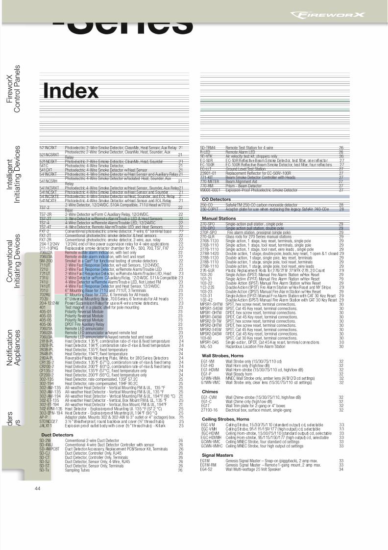
8/10/2019 FX85005-0132 -- FireworX Submittal Guide
http://slidepdf.com/reader/full/fx85005-0132-fireworx-submittal-guide 52/56
C o n t r
o l P a n e l s
I n i t i a t i n g D e v i c e s
I n i t i a t i n g D e v i c e s
A p p l i a n c e s
44
& R e l a y s
V-Series
521NCRXT Photoelectric 2-Wire Smoke Detector, CleanMe, Heat Sensor, Aux Relay 21
521NCSRXTPhotoelectric 2-Wire Smoke Detector, CleanMe, Heat, Sounder, Aux
Relay21
521NCSXT Photoelectric 2-Wire Smoke Detector, CleanMe, Heat, Sounder 21541C Photoelectric 4-Wire Smoke Detector, 21541CXT Photoelectric 4-Wire Smoke Detector w/Heat Sensor 21541NCRXT Photoelectric 4-Wire Smoke Detector w/Heat Sensor and Auxiliary Relay 21
541NCSRHPhotoelectric 4-Wire Smoke Detector w/Isolated Heat, Sounder, Aux
Relay21
541NCSRXT Photoelectric 4-Wire Smoke Detector w/Heat Sensor, Sounder, Aux Relay21
541NCSXT Photoelectric 4-Wire Smoke Detector w/Heat Sensor and Sounder 21541NCSXTE Photoelectric 4-Wire Smoke Detector w/Heat, Sounder, and EOL Relay 21541NCXTE Photoelectric 4-Wire Smoke Detector w/Heat Sensor and EOL Relay 21
TS7-22-Wire Detector, 12/24VDC. S10A Compatible, 711U Head w/701U
Base22
TS7-2R 2-Wire Detector w/Form C Auxiliary Relay, 12/24VDC. 22TS7-2T 2-Wire Detector w/Remote Alarm/Trouble LED & Hea t Sensors 22TS7-4 4-Wire Detector w/Remote Alarm/Trouble LED, 12/24VDC 22TS7-4T 4-Wire Detector, Remote Alarm/Trouble LED and Heat Sensors 22FX7-2 Conventional photoelectric smoke detector, 2-wire, 6” terminal base 22FX7-2T Conventional photoelectric smoke detector & heat sensors 22FX7-2R Convent ional photoelectric smoke detector, 2-wire, aux. relay 22204-12/24V 12/24V, end of l ine power supervision relay for 4-wire applications 22211-10PKG Replaceable smoke detector chamber for FX-, 500, 700, TS7, FX7 22706U2A Remote visible alarm indication, with test only 22706U3A Remote visible alarm indication, with test and reset 22SM-200 Smoke! in a Can® f or functional testing of smoke detectors 22711UT 2-Wire Fast Response Detector, w/Heat Sensors, 12/24VDC. 23721U 2-Wire Fast Response Detector, w/Remote Alarm/Trouble LED 23721UT 2-Wire Fast Response Detector, w/Remote Alarm/Trouble LED, Heat 23731U 2-Wire Detector w/Form C Auxil iary Relay, 12/24VDC. S11A Compatible 23741U 4-Wire Detector w/Remote Alarm/Trouble LED, Not Listed FM 23741UT 4-Wire Fast Response Detector and Heat Sensor, 12/24VDC. 23701U 6” Mounting Base for 711U and 711UT, 3 Terminals 23702RU 6” Mounting Base for 731U, 6 Terminals for All Heads 23702U 6” Universa l Mounting Base, 700 Ser ies, 6 Term inal s for A ll Heads 23204-12/24V Power Superv is ion Relay for use w/4-w ire smoke detectors. 23401 Test magnet in a plastic shell for pole mounting 23405-01 Polarity Reversal Module 23405-03 Polarity Reversal Module 23405-05 Polarity Reversal Module 23405-06 DPDT Fire Auxiliary Relay 23706U1A Remote LED annunciator 23706U2A Remote LED annunciator w/keyed remote test 23706U3A Remote LED annunciator w/keyed remote test and reset 23281B-PL Heat Detector, 135°F, combination rate-of-rise & fixed temperature 24282B-PL Heat Detector, 194°F, combination rate-of-rise & fixed temperature 24283B-PL Heat Detector, 135°F, fixed temperature 24284B-PL Heat Detector, 194°F, fixed temperature 24280A-PL Reversible Plastic Mounting Plate, White, for 280 Series Detectors 24CR135-2 Heat Detector, 135°F (57°C), combination rate-of-rise & fixed temp 24CR200-2 Heat Detector, 200°F (93°C), combination rate-of-rise & fixed temp 24CF135-2 Heat Detector, 135°F (57°C), fixed temperature only 24CF200-2 Heat Detector, 200°F (93°C), fixed temperature only 24302-135 Heat Detector, rate compensated, 135F 57.2C 25
302-194 Heat Detector, rate compensated, 194F 90.2C 25302-AW-135 All-weather Heat Detector - Vertical Mounting FM & UL, 135 °F 25302-AW-135 All-weather Heat Detector - Vertical Mounting FM & UL, 135 °F 25302-AW-194 All-weather Heat Detector - Vertical Mounting FM & UL, 194°F (90 °C) 25302-ET-135 All-weather Heat Detector - Vertical, Box Mount FM & UL, 135 °F 25302-ET-194 All-weather Heat Detector - Vertical, Box Mount, FM & UL, 194°F 25302-EPM-135 Heat Detector - Explosionproof Mounting UL 135 °F (57.2 °C) 25302-EPM-194 Heat Detector - Explos ionproof Mounting UL 194°F (90 °C) 25 AP-P Adaptor plate, Mounts 302 & 302-AW to 3” outlet or 4” (octagon) box. 25STONCO27 3 ½” Weatherproof, round backbox and cover (½” thread hubs) 25JALX11 Exp losion proof ou tl et body wi th cover (½” thread hubs) - Ki ll ark 25
Duct Detectors
SD-2W Conventional 2-wire Duct Detector 26SD-4WJ Conventional 4-wire Duct Detector Controller with sensor 26SD-4WPCBT Duct Detector Accessory, Replacement PCB/Sensor Kit, Terminals 26SD-CJ Duct Detector, Controller Only, RJ45 26SD-CT Duct Detector, Controller Only, Terminals 26SD-SJ Duct Detector, Sensor Only, 4-Wire, RJ45 26SD-ST Duct Detector, Sensor Only, Terminals 26SD-Tx Sampling Tubes 26
SD-TRM4 Remote Test Station for 4 wire 26R-LED Remote Alarm LED 26SD-VTK Air velocity test kit, stoppers only 26EC-50R EC-50R Reflective Beam Smoke Detector, test filter, one reflector 27EC-100R EC-100R Reflective Beam Smoke Detector, test filter, four reflectors 27EC-LLT Ground Level Test Station 2723901-01 Replacement Reflector for EC-50R/-100R 27771-KIT Beam Smoke Detector Controller with Heads 27770-METER Beam Alignment Aid 27770-RM Prism - Beam Detector 27V9006-0001 Explosion-Proof Photoelectric Smoke Detector 27
CO Detectors
250-CO SafeAirTM 250-CO carbon monoxide detector 28250-COPLT Adaptor plate for use when replacing the legacy SafeAir 240-COe 28
Manual Stations
270-SPO Single-action pull station, single pole 29270-DPO Single action pull station, double pole 29270P-SPO Fire alarm station, presignal (single pole) 29270-GLR Glass rods for 270 Series manual stations 29276B-1120 Single action, 1 stage, key reset, terminals, single pole 29276B-1110 Single action, 1 stage, tool reset, terminals, single pole 29277B-1110 Single action, 1 stage, tool r eset, wire leads , single pole 29278B-1420 Double action, 1 stage, double pole, leads, key reset, 1 open & 1 closed 29278B-1120 Double action, 1 stage, single pole, key reset, terminals 29278B-1110 Double act ion, 1 stage, single pole, tool reset , terminals 29279B-1110 Double act ion, 1 stage, single pole, tool reset , wire leads 29276-GLR Plast ic Replacement Rods fo r 276/278/ 279/FX-278, 20 Count 29103-20 Single Action (SPST) Manual Fire Alarm Station w/Hex Reset 29103-21 Single Action (DPST) Manual Fire Alarm Station w/Hex Reset 29103-22 Double Action (SPST) Manual Fire Alarm Station w/Hex Reset 29
103-22S Double Action (SPST) Fi re Alarm Station w/Hex Reset and NY Stripe 29103-23 Double Act ion (DPST) Manual Fire Alarm Sta tion w/Hex Reset 29103-31 Single Action (SPST) Manual Fire Alarm Station with CAT 30 Key Reset 29103-42 Double Action (SPST) Manual Fire Alarm Station with CAT 30 Key Reset 29MPSR1-SHTW SPST, hex screw reset, terminal connections. 30MPSR1-S45W SPST, Cat 45 Key reset, terminal connections. 30MPSR1-DHTW DPDT, hex screw reset, terminal connections. 30MPSR1-D45W DPDT, Cat 45 Key reset, terminal connections. 30MPSR2-SHTW SPST, hex screw reset, terminal connections. 30MPSR2-DHTW DPDT, hex screw reset, terminal connections. 30MPSR2-S45W SPST, Cat 45 Key reset, terminal connections. 30MPSR2-D45W DPDT, Cat 45 Key reset, terminal connections. 30103-60 SPST, Cat 30 Key reset, terminal connections. 30MPSR1-D45 Single-act ion, DPDT, Cat 45 Key reset, termina l connect ions 30 XAL-53 Hazardous Location Fire Alarm Station 30
Wall Strobes, Horns
EG1-VM Wall Strobe only (15/30/75/110 cd) 32 EG1-HD Wall Horn only (high/low dB) 32 EG1-HDVM Wall Horn-strobe (15/30/75/110 cd, high/low dB) 32 EG1-P Wall Steady horn 32 G1WN-VMA MNEC Wall Strobe only, amber lens (A/B/C/D cd set tings) 32 G 1WN-VMC Wall Strobe only, clear lens (15/30/75/110 cd settings) 32
Chimes
EG1-CVM Wall Chime-strobe (15/30/75/110, high/low dB) 32 EG1-C Wall Chime only (high/low dB) 32 EG1T Wall Trim plate for 2-gang or 4” boxes 32 27193-16 Electrical box, surface mount, single-gang 32
Ceiling Strobes, Horns
EGC-VM Ceil ing S trobe, 15/30/75/110 (standard output) cd, selec table 33 EGC-VMH Ceil ing S trobe, 95/115/150/177 (high output ) cd, selec table 33 EGC-HDVM Ceiling Horn-strobe, 15/30/75/110 (standard output) cd, selectable 33 EGC-HDVMH Ceiling Horn-strobe, 95/115/150/177 (high output) cd, selectable 33 GCWN-VMC Ceiling MNEC Strobe, four standard cd settings 33 GCWN-VMHC Ceiling MNEC Strobe, four high output cd settings 33
Signal Masters
EG1M Genesis Signal Master – Snap-on (piggyback), 2 amp max. 33EG1M-RM Genesis Signal Master – Remote 1-gang mount , 2 amp max. 33EG4-S2 Wall Multi-wattage 25 Volt Speaker 34
Index
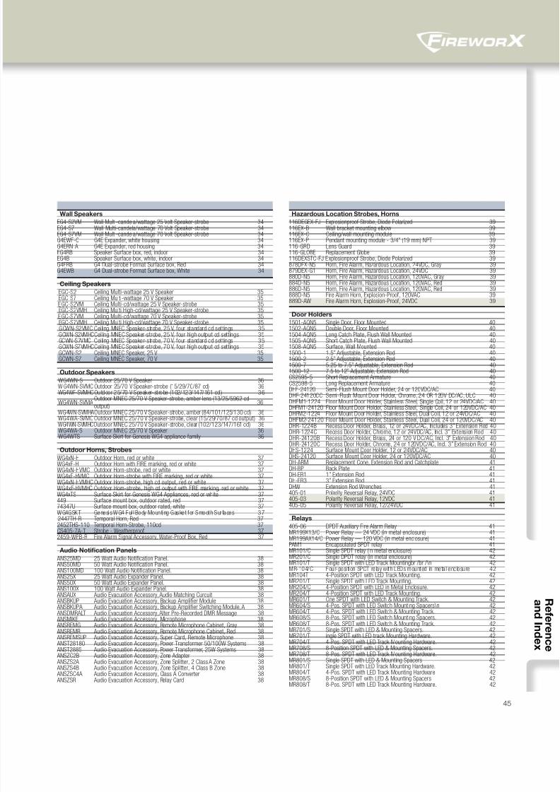
8/10/2019 FX85005-0132 -- FireworX Submittal Guide
http://slidepdf.com/reader/full/fx85005-0132-fireworx-submittal-guide 53/5645
Wall Speakers
EG4-S2VM Wall Multi-candela/wattage 25 Volt Speaker-strobe 34EG4-S7 Wall Multi-candela/wattage 70 Volt Speaker-strobe 34EG4-S7VM Wall Multi-candela/wattage 70 Volt Speaker-strobe 34G4EWF-C G4E Expander, white housing 34G4ERN-A G4E Expander, red housing 34EG4RB Speaker Surface box, red, indoor 34EG4B Speaker Surface box, white, indoor 34G4ERB G4 Dual-strobe Format Surface box, Red 34G4EWB G4 Dual-strobe Format Surface box, White 34
Ceiling Speakers
EGC-S2 Ceiling Multi-wattage 25 V Speaker 35 EGC-S7 Ceiling Multi-wattage 70 V Speaker 35 EGC-S2VM Ceiling Multi-cd/wattage 25 V Speaker-strobe 35 EGC-S2VMH Ceiling Multi High-cd/wattage 25 V Speaker-strobe 35 EGC-S7VM Ceiling Multi-cd/wattage 70 V Speaker-strobe 35 EGC-S7VMH Ceiling Multi High-cd/wattage 70 V Speaker-strobe 35 GCWN-S2VMC Ceiling MNEC Speaker-strobe, 25 V, four standard cd settings 35 GCWN-S2VMHCCeiling MNEC Speaker-strobe, 25 V, four high output cd settings 35 GCWN-S7VMC Ceiling MNEC Speaker-strobe, 70 V, four standard cd settings 35 GCWN-S7VMHCCeiling MNEC Speaker-strobe, 70 V, four high output cd settings 35 GCWN-S2 Ceiling MNEC Speaker, 25 V 35 GCWN-S7 Ceiling MNEC Speaker, 70 V 35
Outdoor Speakers
WG4WN-S Outdoor 25/70 V Speaker 36 W G4WN-SVMC Outdoor 25/70 V Speaker-strobe (15/29/70/87 cd) 36 WG4WF-SVMHCOutdoor 25/70 V Speaker-st robe (102/123/147/161 cd ) 36
WG4WN-SVMAOutdoor MNEC 25/70 V Speaker-strobe, amber lens (13/25/5962 cd
output)36
WG4WN-SVMHAOutdoor MNEC 25/70 V Speaker-strobe, amber (84/101/125/130 cd) 36 WG4WA-SVMC Outdoor MNEC 25/70 V Speaker-strobe, clear (15/29/70/87 cd output) 36 WG4WN-SVMHCOutdoor MNEC 25/70 V Speaker-strobe, clear (102/123/147/161 cd) 36 WG4WA-S Outdoor MNEC 25/70 V Speaker 36 WG4WTS Surface Skirt for Genesis WG4 appliance family. 36
Outdoor Horns, Strobes
WG4xN-H Outdoor Horn, red or white 37WG4xF-H Outdoor Horn with FIRE marking, red or white 37WG4xN-HVMC Outdoor Horn-strobe, red or white 37WG4xF-HVMC Outdoor Horn-strobe with FIRE marking, red or white 37WG4xN-HVMHC Outdoor Horn-strobe, high cd output, red or white 37WG4xF-HVMHC Outdoor Horn-strobe, high cd output with FIRE marking, red or white 37WG4xTS Surface Skirt for Genesis WG4 Appliances, red or white 37449 Surface mount box, outdoor rated, red 3774347U Surface mount box, outdoor rated, white 37WG4GSKT Genesi s WG4 Ful l Body Mounting Gasket for Smooth Sur faces 37 2447TH-R Temporal Horn, Red 372452THS-110 Temporal Horn-Strobe, 110cd 37CS405-7A-T Strobe - Weatherproof 372459-WPB-R Fire Alarm Signal Accessory, Water-Proof Box, Red 37
Audio Notification Panels
ANS25MD 25 Watt Audio Notification Panel. 38 ANS50MD 50 Watt Audio Notification Panel. 38 ANS100MD 100 Watt Audio Notification Panel. 38 ANS25X 25 Watt Audio Expander Panel. 38 ANS50X 50 Watt Audio Expander Panel. 38 ANS100X 100 Watt Audio Expander Panel. 38 ANSAUX Audio Evacuation Accessory, Audio Matching Curcuit 38 ANSBKUP Audio Evacuation Accessory, Backup Amplifier Module 38 ANSBKUPA Audio Evacuation Accessory, Backup Amplifier Switching Module, A 38 ANSDMRALT Audio Evacuation Accessory, Alter Pre-Recorded DMR Message 38 ANSMIKE Audio Evacuation Accessory, Microphone 38 ANSREMG Audio Evacuation Accessory, Remote Microphone Cabinet, Gray 38 ANSREMR Audio Evacuation Accessory, Remote Microphone Cabinet, Red 38 ANSREMSUP Audio Evacuation Accessory, Super Card, Remote Microphone 38 ANST28180 Audio Evacuation Accessory, Power Transformer 50/100W Systems 38 ANST2885 Audio Evacuation Accessory, Power Transformer, 25W Systems 38 ANSZC2B Audio Evacuation Accessory, Zone Adapter 38 ANSZS2A Audio Evacuation Accessory, Zone Splitter, 2 Class A Zone 38 ANSZS4B Audio Evacuation Accessory, Zone Splitter, 4 Class B Zone 38 ANSZSC4A Audio Evacuation Accessory, Class A Converter 38 ANSZSR Audio Evacuation Accessory, Relay Card 38
Hazardous Location Strobes, Horns
116DEGEX-FJ Explosionproof Strobe, Diode Polarized 39116EX-B Wall bracket mounting elbow 39116EX-C Ceiling/wall mounting module 39116EX-P Pendant mounting module - 3/4” (19 mm) NPT 39116-GRD Lens Guard 39116-GLOBE Replacement Globe 39116DEXSTC-FJ Explosionproof Strobe, Diode Polarized 39878DEX-N5 Horn, Fire Alarm, Hazardous Location, 24VDC, Gray 39879DEX-G1 Horn, Fire Alarm, Hazardous Location, 24VDC 39
880D-N5 Horn, Fire Alarm, Hazardous Location, 120VAC, Gray 39884D-N5 Horn, Fire Alarm, Hazardous Location, 120VAC, Red 39886D-N5 Horn, Fire Alarm, Hazardous Location, 120VAC, Red 39888D-N5 Fire Alarm Horn, Explosion-Proof, 120VAC 39889D-AW Fire Alarm Horn, Explosion-Proof, 24VDC 39
Door Holders
1501-AQN5 Single Door, Floor Mounted 401502-AQN5 Double Door, Floor Mounted 401504-AQN5 Long Catch Plate, Flush Wall Mounted 401505-AQN5 Short Catch Plate, Flush Wall Mounted 401508-AQN5 Surface, Wall Mounted 401500-1 1.5” Adjustable, Extension Rod 401500-2 2.5” Adjustable, Extension Rod 401500-7 5.25 to 7.5” Adjustable, Extension Rod 401500-12 7.5 to 12” Adjustable, Extension Rod 40CS2595-5 Short Replacement Armature 40CS2598-5 Long Replacement Armature 40DHF-24120 Semi-Flush Mount Door Holder, 24 or 120VDC/AC 40DHF-24120CC Semi-Flush Mount Door Holder, Chrome, 24 OR 120V DC/AC, ULC 40DHFM1-1224 Floor Mount Door Holder, Stainless Steel, Single Coil, 12 or 24VDC/AC 40DHFM1-24120 Floor Mount Door Holder, Stainless Steel, Single Coil, 24 or 120VDC/AC 40
DHFM2-1224 Floor Mount Door Holder, Stainless Steel, Dual Coil, 12 or 24VDC/AC 40DHFM2-24120 Floor Mount Door Holder, Stainless Steel, Dual Coil, 24 or 120VDC/AC 40DHR-1224B Recess Door Holder, Brass, 12 or 24VDC/AC, Includes 3” Extension Rod 40DHR-1224C Recess Door Holder, Chrome, 12 or 24VDC/AC, Incl. 3” Extension Rod 40DHR-24120B Recess Door Holder, Brass, 24 or 120 V DC/AC, Incl. 3” Extension Rod 40DHR-24120C Recess Door Holder, Chrome, 24 or 120VDC/AC, Incl. 3” Extension Rod 40DHS-1224 Surface Mount Door Holder, 12 or 24VDC/AC 40DHS-24120 Surface Mount Door Holder, 24 or 120VDC/AC 40DH-ARM Replacement Cone, Extension Rod and Catchplate 41DH-BP Back Plate 41DH-ER1 1” Extension Rod 41DH-ER3 3” Extension Rod 41DHW Extension Rod Wrenches 41405-01 Polarity Reversal Relay, 24VDC 41405-03 Polarity Reversal Relay, 12VDC 41405-05 Polarity Reversal Relay, 12/24VDC 41
Relays
405-06 DPDT Auxiliary Fire Alarm Relay 41MR199X13/C Power Relay — 24 VDC (in metal enclosure) 41MR199AX14/C Power Relay — 120 VDC (in metal enclosure) 41PAM1 Encapsulated SPDT relay 41MR101/C Single SPDT relay (in metal enclosure) 42MR201/C Single DPDT relay (in metal enclosure) 42MR101/T Single SPDT with LED Track Mountingbr /br /\n 42MR-104/C Four-posi tion SPDT relay with LEDs mounted in metal enclosure 42MR104T 4-Position SPDT with LED Track Mounting. 42MR201/T Single SPDT with LED Track Mounting. 42MR204/C 4-Position SPDT with LED in Metal Enclosure. 42MR204/T 4-Position SPDT with LED Track Mounting. 42MR601/T One SPDT with LED Switch & Mounting Track. 42MR604/S 4-Pos. SPDT with LED Switch Mounting Spacers\n 42MR604/T 4-Pos. SPDT with LED Switch & Mounting Track. 42MR608/S 8-Pos. SPDT with LED Switch Mounting Spacers. 42MR608/T 8-Pos. SPDT with LED Switch & Mounting Track. 42MR701/S Single SPDT with LED & Mounting Spacers. 42MR701/T ingle SPDT with LED track Mounting Hardware. 42MR704/T 4-Pos. SPDT with LED Track Mounting Hardware. 42MR708/S 8-Position SPDT with LED & Mounting Spacers. 42MR708/T 8-Pos. SPDT with LED Track Mounting Hardware. 42MR801/S Single SPDT with LED & Mounting Spacers 42MR801/T Single SPDT with LED Track Mounting Hardware. 42MR804/T 4-Pos. SPDT with LED Track Mounting Hardware 42MR808/S 8-Position SPDT with LED & Mounting Spacers 42MR808/T 8-Pos. SPDT with LED Track Mounting Hardware. 42
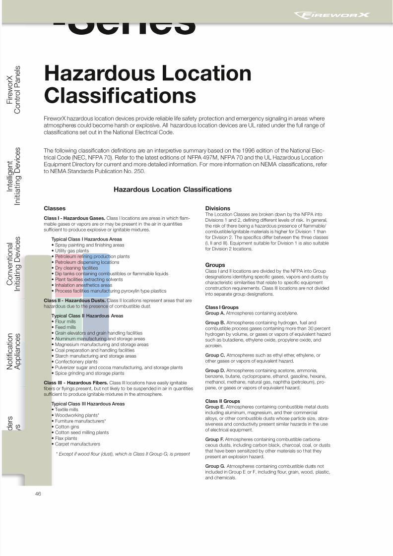
8/10/2019 FX85005-0132 -- FireworX Submittal Guide
http://slidepdf.com/reader/full/fx85005-0132-fireworx-submittal-guide 54/56
C o n t r
o l P a n e l s
I n i t i a t i n g D e v i c e s
I n i t i a t i n g D e v i c e s
A p p l i a n c e s
46
& R e l a y s
V-SeriesHazardous Location
Classifications
Classes
Class I - Hazardous Gases. Class I locations are areas in which flam-
mable gases or vapors are or may be present in the air in quantities
sufficient to produce explosive or ignitable mixtures.
Typical Class I Hazardous Areas
• Spray painting and finishing areas
• Utility gas plants
• Petroleum refining production plants
• Petroleum dispensing locations
• Dry cleaning facilities
• Dip tanks containing combustibles or flammable liquids
• Plant facilities extracting solvents
• Inhalation anesthetics areas
• Process facilities manufacturing pyroxylin type plastics
Class II - Hazardous Dusts. Class II locations represent areas that are
hazardous due to the presence of combustible dust.
Typical Class II Hazardous Areas
• Flour mills
• Feed mills
• Grain elevators and grain handling facilities
• Aluminum manufacturing and storage areas
• Magnesium manufacturing and storage areas
• Coal preparation and handling facilities
• Starch manufacturing and storage areas
• Confectionery plants
• Pulverizer sugar and cocoa manufacturing, and storage plants
• Spice grinding and storage plants
Class III - Hazardous Fibers. Class III locations have easily ignitable
fibers or flyings present, but not likely to be suspended in air in quantitiessufficient to produce ignitable mixtures in the atmosphere.
Typical Class III Hazardous Areas
• Textile mills
• Woodworking plants*
• Furniture manufacturers*
• Cotton gins
• Cotton seed milling plants
• Flax plants
• Carpet manufacturers
* Except if wood flour (dust), which is Class II Group G, is present
Divisions The Location Classes are broken down by the NFPA into
Divisions 1 and 2, defining different levels of risk. In general,
the risk of there being a hazardous presence of flammable/
combustible/ignitable materials is higher for Division 1 than
for Division 2. The specifics differ between the three classes
(I, II and III). Equipment suitable for Division 1 is also suitable
for Division 2 locations.
GroupsClass I and II locations are divided by the NFPA into Group
designations identifying specific gases, vapors and dusts by
characteristic similarities that relate to specific equipment
construction requirements. Class III locations are not divided
into separate group designations.
Class I Groups
Group A. Atmospheres containing acetylene.
Group B. Atmospheres containing hydrogen, fuel and
combustible process gases containing more than 30 percent
hydrogen by volume, or gases or vapors of equivalent hazard
such as butadiene, ethylene oxide, propylene oxide, and
acrolein.
Group C. Atmospheres such as ethyl ether, ethylene, or
other gases or vapors of equivalent hazard.
Group D. Atmospheres containing acetone, ammonia,
benzene, butane, cyclopropane, ethanol, gasoline, hexane,
methanol, methane, natural gas, naphtha (petroleum), pro-
pane, or gases or vapors of equivalent hazard.
Class II Groups
Group E. Atmospheres containing combustible metal dusts,
including aluminum, magnesium, and their commercial
alloys, or other combustible dusts whose particle size, abra-
siveness and conductivity present similar hazards in the use
of electrical equipment.
Group F. Atmospheres containing combustible carbona-
ceous dusts, including carbon black, charcoal, coal, or dusts
that have been sensitized by other materials so that they
present an explosion hazard.
Group G. Atmospheres containing combustible dusts not
included in Group E or F, including flour, grain, wood, plastic,
and chemicals.
FireworX hazardous location devices provide reliable life safety protection and emergency signaling in areas where
atmospheres could become harsh or explosive. All hazardous location devices are UL rated under the full range of
classifications set out in the National Electrical Code.
The following classification definitions are an interpretive summary based on the 1996 edition of the National Elec-
trical Code (NEC, NFPA 70). Refer to the latest editions of NFPA 497M, NFPA 70 and the UL Hazardous Location
Equipment Directory for current and more detailed information. For more information on NEMA classifications, refer
to NEMA Standards Publication No. 250.
Hazardous Location Classifications

8/10/2019 FX85005-0132 -- FireworX Submittal Guide
http://slidepdf.com/reader/full/fx85005-0132-fireworx-submittal-guide 55/56

8/10/2019 FX85005-0132 -- FireworX Submittal Guide
http://slidepdf.com/reader/full/fx85005-0132-fireworx-submittal-guide 56/56
Built on a rich legacy of innovation.
Focused squarely on the future.
FireworX offers powerful solutions that protect people and
property with some of the most innovative fire alarm tech-
nology ever developed. From integrated life safety systems
to intuitive programming and configuration, all our products
undergo rigorous scrutiny throughout their development to
make sure they bring long-term value to every application. So
it comes as no surprise that our life safety solutions can be
found maintaining safe environments in some of the world’s
most important buildings.
When you invest in FireworX fire alarm products you invest in
a legacy that spans more than a century of innovation, and a
corporate culture that focuses squarely on the future. We’re
already at the forefront of emerging new technologies. And
we’re investing heavily in fire alarm solutions that will make
your world safer.
See what’s possible now.Talk to your FireworX
distributor today.
Contact us...
Email: [email protected]
Web: www.edwardsfire.com
FireworX is anEDWARDS brand.
8985 Town Center Parkway
Bradenton, FL 34202
© 2013 UTC Fire & Security Americas
Corporation, Inc. All rights reserved.
Specifications subject to change
without notice. Edwards is part of UTC
Climate, Controls & Security, a unit of
United Technologies Corporation.