Embed Size (px)
Citation preview
24590-CM-HC4-HXYG-00138 -02 - 00047 OOA PO/SCT Submittal Rev
• Joh No. 24590
______ -~eview not reqnired. Work mav eed. Permission to proceed does not constitute acceptance or approval of design details, calculations, analyses, test methods, or materials developed or selected by the supplier and does not relieve supplier from full compliance with contractual obligations.
G-321 DocumentCategory __ __.....__'-+--------------[From Supplement A to G-321-E (E) or
Thue
'--------------------------- TP0406_34i--04
SUBCONTRACT SUBMITTAL
Best Available Copy
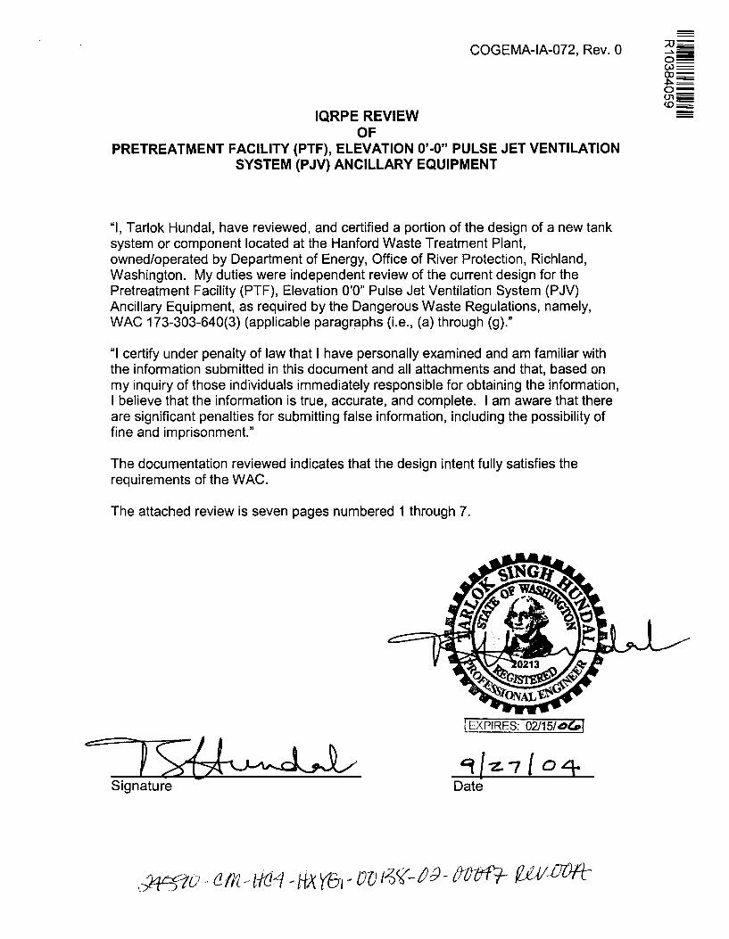
IQRPE REVIEW OF
COGEMA-IA-072, Rev. 0
PRETREATMENT FACILITY (PTF), ELEVATION 0'-0" PULSE JET VENTILATION SYSTEM (PJV) ANCILLARY EQUIPMENT
"I, Tarlok Hundal, have reviewed, and certified a portion of the design of a new tank system or component located at the Hanford Waste Treatment Plant, owned/operated by Department of Energy, Office of River Protection, Richland, Washington. My duties were independent review of the current design for the Pretreatment Facility (PTF}, Elevation O'O" Pulse Jet Ventilation System (PJV) Ancillary Equipment, as required by the Dangerous Waste Regulations, namely, WAC 173-303-640(3) (applicable paragraphs (i.e., (a) through (g)."
"I certify under penalty of law that I have personally examined and am familiar with the information submitted in this document and all attachments and that, based on my inquiry of those individuals immediately responsible for obtaining the information, I believe that the information is true, accurate, and complete. I am aware that there are significant penalties for submitting false information, including the possibility of fine and imprisonment."
The documentation reviewed indicates that the design intent fully satisfies the requirements of the WAC.
The attached review is seven pages numbered 1 through 7.
==-f SJJ~ Signature
COGEMA-IA-072, Rev. 0
STRUCTURAL INTEGRITY ASSESSMENT OF THE PRETREATMENT FACILITY (PTF), ELEVATION 0'-0"
PULSE JET VENTILATION SYSTEM (PJV) ANCILLARY EQUIPMENT
COGEMA-IA-072
REV. 0
Please note that source, special nuclear and byproduct materials, as defined in the Atomic Energy Act of 1954 (AEA), are regulated at the U.S. Department of Energy (DOE) facilities exclusively by DOE acting pursuant to its AEA authority. DOE asserts, that pursuant to the AEA, it has sole and exclusive responsibility and authority to regulate source, special nuclear, and byproduct materials at DOE-owned nuclear facilities. Information contained herein on radionuclides is provided for process description purposes only.
Pretreatment Facility (PTF) Elev. 0'-0" Pulse Jet Ventilation System (PJV) Ancillary Equipment
COGEMA-IA-072, Rev. 0
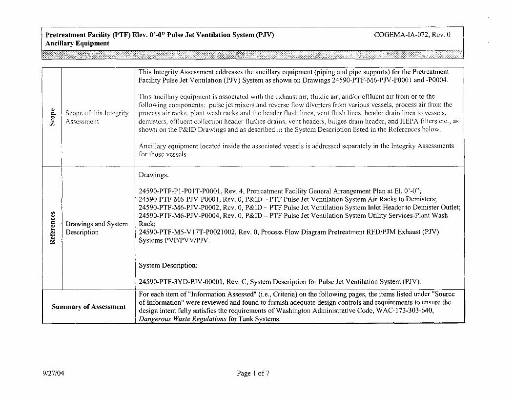
This Integrity Assessment addresses the ancillary equipment (piping and pipe supports) for the Pretreatment Facility Pulse Jet Ventilation (PJV) System as shown on Drawings 24590-PTF-M6-PJV-P0001 and -P0004.
This ancillary equipment is associated with the exhaust air, fluidic air, and/or effluent air from or to the
CJ following components: pulse jct mixers and reverse flow diverters from various vessels, process air from the
C. Scope of this Integrity process air racks, plant wash racks and the header flush lines, vent flush lines, header drain lines to vessels, 0 u Assessment demisters, effluent collection header flushes drains, vent headers, bulges drain header, and HEPA filters etc., as VJ
shown on the P&ID Drawings and as described in the System Description listed in the References below.
Ancillary equipment located inside the associated vessels is addressed separately in the Integrity Assessments for those vessels.
Drawings:
24590-PTF-Pl-P0lT-P000l, Rev. 4, Pretreatment Facility General Arrangement Plan at El. 0'-0"; 24590-PTF-M6-PJV-P0001, Rev. 0, P&ID - PTF Pulse Jet Ventilation System Air Racks to Demisters; 24590-PTF-M6-PJV-P0002, Rev. 0, P&ID - PTF Pulse Jet Ventilation System Inlet Header to Demister Outlet;
"' 24590-PTF-M6-PJV-P0004, Rev. 0, P&ID- PTF Pulse Jet Ventilation System Utility Services-Plant Wash Cl.I u C: Drawings and System Rack; Q,j - Description 24590-PTF-MS-Vl 7T-P0021002, Rev. 0, Process Flow Diagram Pretreatment RFD/PJM Exhaust (PJV) ~ Q,j Systems PVP/PVV/PJV. ~
System Description:
24590-PTF-3YD-PJV-00001, Rev. C, System Description for Pulse Jet Ventilation System (PJV).
For each item of "Information Assessed" (i.e., Criteria) on the following pages, the items listed under "Source
Summary of Assessment of Information" were reviewed and found to furnish adequate design controls and requirements to ensure the design intent fully satisfies the requirements of Washington Administrative Code, W AC-173-303-640, Danf(erous Waste Rewlations for Tank Systems.
9/27/04 Page 1 of 7
Pretreatment Facility (PTF) Plant Wash and Disposal System (PJV) Ancillary Equipment
I Information Assessed I Source of Information
Drawings and System Description listed above under References;
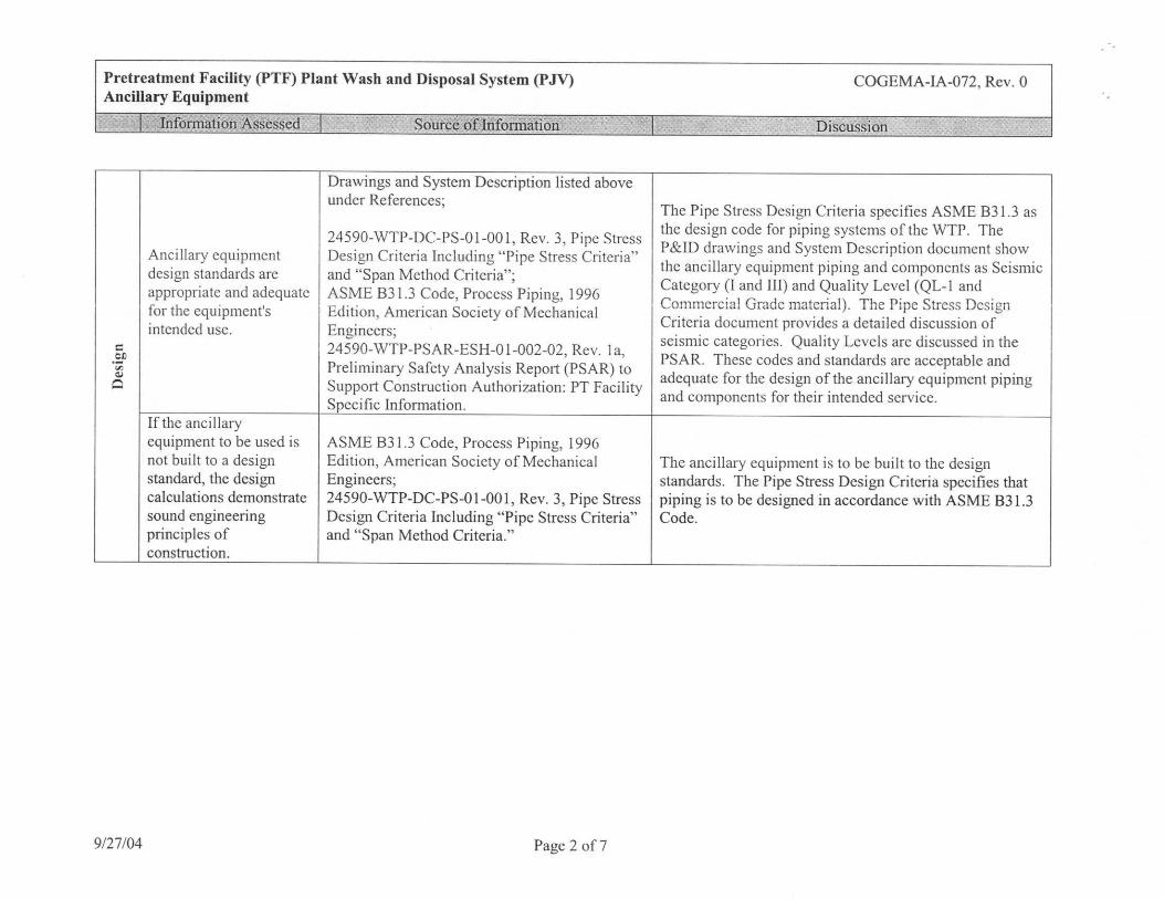
24590-WTP-DC-PS-01-001, Rev. 3, Pipe Stress Ancillary equipment Design Criteria Including "Pipe Stress Criteria" design standards are and "Span Method Criteria"; appropriate and adequate ASME B31.3 Code, Process Piping, 1996 for the equipment's Edition, American Society of Mechanical intended use. Engineers;
-~ 24590-WTP-PSAR-ESH-01-002-02, Rev. la,
"' Preliminary Safety Analysis Report (PSAR) to Q,I
0 Support Construction Authorization: PT Facility Specific Information.
If the ancillary equipment to be used is ASME B31.3 Code, Process Piping, 1996 not built to a design Edition, American Society of Mechanical standard, the design Engineers; calculations demonstrate 24590-WTP-DC-PS-01-001, Rev. 3, Pipe Stress sound engineering Design Criteria Including "Pipe Stress Criteria" principles of and "Span Method Criteria." construction.
9/27/04 Page 2 of7
COGEMA-IA-072, Rev. 0
l Discussion
The Pipe Stress Design Criteria specifies ASME B31.3 as the design code for piping systems of the WTP. The P&ID drawings and System Description document show the ancillary equipment piping and components as Seismic Category (I and III) and Quality Level (QL-1 and Commercial Grade material). The Pipe Stress Design Criteria document provides a detailed discussion of seismic categories. Quality Levels are discussed in the PSAR. These codes and standards arc acceptable and adequate for the design of the ancillary equipment piping and components for their intended service.
The ancillary equipment is to be built to the design standards. The Pipe Stress Design Criteria specifies that piping is to be designed in accordance with ASME B31.3 Code.
Pretreatment Facility (PTF) Plant Wash and Disposal System (PJV) Ancillary Equipment
I Information Assessed I Source of Information --
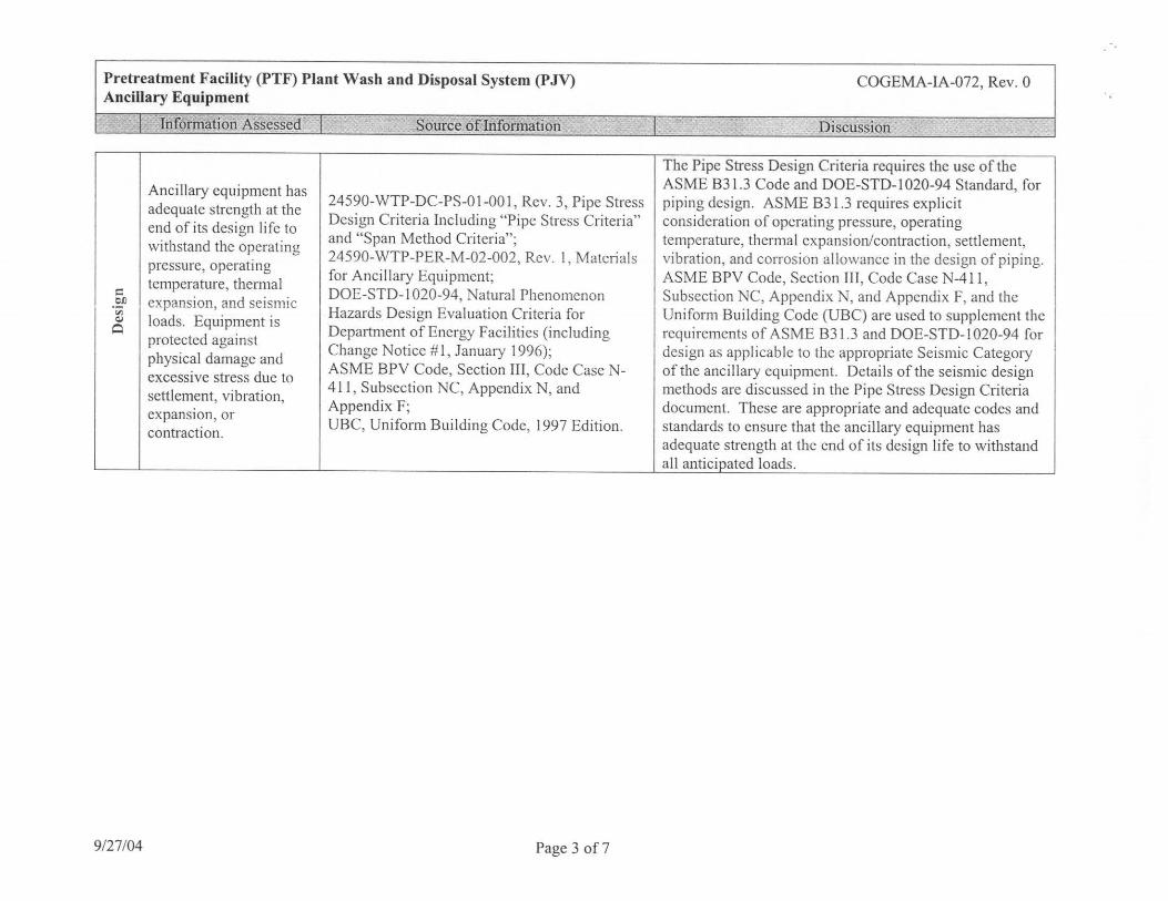
Ancillary equipment has adequate strength at the 24590-WTP-DC-PS-01-001, Rev. 3, Pipe Stress
end of its design life to Design Criteria Including "Pipe Stress Criteria"
withstand the operating and "Span Method Criteria";
pressure, operating 24590-WTP-PER-M-02-002, Rev. 1, Materials
temperature, thcrn1al for Ancillary Equipment; C DOE-STD- I 020-94, Natural Phenomenon CJ) expansion, and seismic V) Hazards Design Evaluation Criteria for Qj loads. Equipment is Q
protected against Dcpaitment of Energy Facilities (including
physical damage and Change Notice # 1, January 1996);
excessive stress due to ASME BPV Code, Section III, Code Case N-
settlement, vibration, 411, Subsection NC, Appendix N, and Appendix F; expansion, or UBC, Uniform Building Code, 1997 Edition. contraction.
9/27/04 Page 3 of7
COGEMA-IA-072, Rev. 0
l Discussion
The Pipe Stress Design Criteria requires the use of the ASME B3 l .3 Code and DOE-STD-1020-94 Standard, for piping design. ASME B3 l .3 requires explicit consideration of operating pressure, operating temperature, thermal expansion/contraction, settlement, vibration, and corrosion allowance in the des ign of piping. ASME BPV Code, Section III, Code Case N-411, Subsection NC, Appendix N, and Appendix F, and the Uniform Building Code (UBC) are used to supplement the requirements of ASME B31.3 and DOE-STD- I 020-94 for design as applicable to the appropriate Seismic Category of the ancillary equipment. Details of the seismic design methods are discussed in the Pipe Stress Design Criteria document. These are appropriate and adequate codes and standards to ensure that the ancillary equipment has adequate strength at the end of its design life to withstand all anticipated loads.
Pretreatment Facility (PTF) Plant Wash and Disposal System (PJV) Ancillary Equipment
J~!nformation Assessed I Source of Information
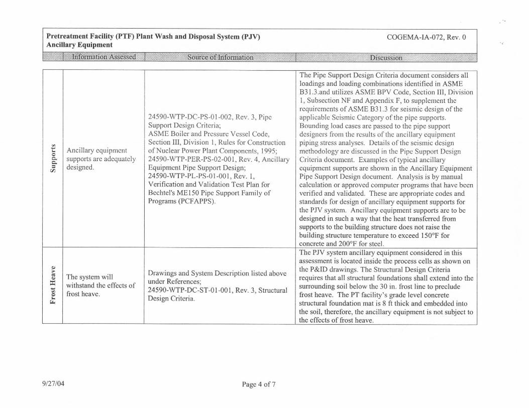
24590-WTP-DC-PS-0 1-002, Rev. 3, Pipe Support Design Criteria; ASME Boiler and Pressure Vessel Code,
"' Section III, Divis ion 1, Rules for Construction
..... Ancillary equipment of Nuclear Power Plant Components, 1995; .. 0 c.. supports are adequately 24590-WTP-PER-PS-02-001, Rev. 4, Ancillary c.. = designed. Equipment Pipe Support Design;
r:J)
24590-WTP-PL-PS-01-001 , Rev. 1, Verification and Validation Test Plan for Bechtel's ME150 Pipe Support Family of Programs (PCF APPS).
~ ;.. Drawings and System Description listed above ~ The system will ~
under References; ::i:: withstand the effects of ..... 24590-WTP-DC-ST-0 1-00 I , Rev. 3, Structural "' frost heave. 0 Design Criteria . ..
~
9/27/04 Page 4 of 7
COGEMA-IA-072, Rev. 0
l Discussion
The Pipe Support Design Criteria document considers all loadings and loading combinations identified in ASME B3 l.3 .and utilizes ASME BPV Code, Section III, Division 1, Subsection NF and Appendix F, to supplement the requirements of ASME B3 l .3 for seismic design of the applicable Seismic Category of the pipe supports. Bounding load cases are passed to the pipe support designers from the results of the ancillary equipment piping stress analyses. Details of the seismic design methodology are discussed in the Pipe Suppo11 Design Criteria document. Examples of typical ancillary equipment supports are shown in the Ancillary Equipment Pipe Support Design document. Analysis is by manual calculation or approved computer programs that have been verified and validated. These are appropriate codes and standards for design of ancillary equipment supports for the PJV system. Ancillary equipment supports arc to be designed in such a way that the heat transferred from supports to the building structure does not raise the building structure temperature to exceed 150°F for concrete and 200°F for steel. The PJV system ancillary equipment considered in this assessment is located inside the process cells as shown on the P&ID drawings. The Structural Design Criteria requires that all structural foundations shall extend into the surrounding soil below the 30 in. frost line to preclude frost heave. The PT facility 's grade level concrete structural foundation mat is 8 ft thick and embedded into the soil, therefore, the ancillary equipment is not subject to the effects of frost heave.
Pretreatment Facility (PTF) Plant Wash and Disposal System (PJV) Ancillary Equipment
"' ::: 0
:;:: u C)
::: ::::: 0 u
"' .:! -"' "i: C) -u ~ I. ~
..c: u C) -"' ~ ~
I
9/27/04
Information Assessed
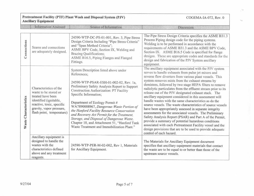
Seams and connections are adequately designed.
Characteristics of the waste to be stored or treated have been identified (ignitable, reactive, toxic, specific gravity, vapor pressure, flash point, temperature)
Ancillary equipment is designed to handle the wastes with the characteristics defined above and any treatment reagents.
I Source of Information
24590-WTP-DC-PS-01-001 , Rev. 3, Pipe Stress Design Criteria Including " Pipe Stress Criteria"
1
and "Span Method Criteria"; ASME BPV Code, Section IX, Welding and Brazing Qualifications; ASME B 16.5, Piping Flanges and Flanged Fittings. ---
System Description listed above under References;
24590-WTP-PSAR-ESH-0 1-002-02, Rev. I a, Preliminary Safety Analysis Report to Support Construction Authorization: PT Facility Specific Information;
Department of Ecology Pemut # WA 7890008967, Dangerous Waste Portion of the Hanford Facility Resource Conservation and Recovery Act Permit for the Treatment, Storage, and Disposal of Dangerous Waste, Chapter 10, and Attachment 51 , "Hanford Tank Waste Treatment and Immobilization Plant."
124590-WTP-PER-M-02-002, Rev 1, Materials for Ancillary Equipment.
Page 5 of 7
I
COGEMA-IA-072, Rev. 0
Discussion
The Pipe Stress Design Criteria specifics the ASME B31.3 Process Piping design code for the piping systems. Welding is to be performed in accordance with the requirements of ASME B31.3 and the ASME BPV Code, Section IX. ASME B 16.5 Code is specified for flange designs. These arc appropriate codes and standards for the design and fabrication of the PJV System ancillary ~mcnt. The ancillary equipment associated with the PJV system serves to handle exhausts from pulse jct mixers and reverse flow divc1ters from various plant vessels. This system removes mists from the exhaust streams by demisters, followed by two stage HEPA filters to remove radiolytic particulates from the effluent stream prior to its release out of the P N designated exhaust stack. The ancillary equipment considered in this assessment will handle wastes with the same characteristics as do the source vessels. The waste characteristics of source vessels have been appropriately assessed in separate integrity assessments for the associated vessels. The Preliminary Safety Analysis Report (PSAR) and Part A of the Permit, provide a summary of potential hazardous conditions associated with each Pretreatment Facility vessel and the design provisions that are to be used to provide adequate control of each hazard.
The Materials for Ancillary Equipment document specifies that ancillary equipment materials that contact the waste are to be equal to or better than those of the upstream source vessels.
..
Pretreatment Facility (PTF) Plant Wash and Disposal System (PJV) Ancillary Equipment
I Information Assessed I Source of Information
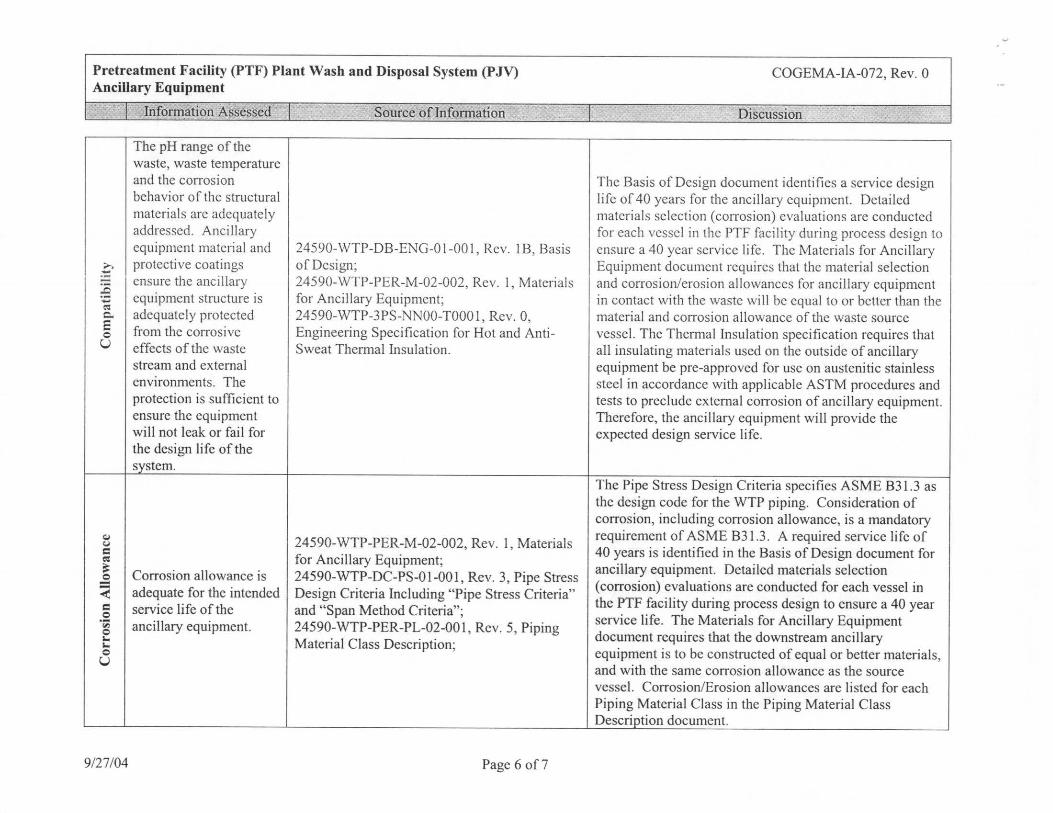
The pH range of the waste, waste temperature and the corrosion behavior of the structural materials arc adequately addressed. Ancillary equipment material and 24590-WTP-DB-ENG-01-001, Rev. 1B, Basis
;,-, protective coatings of Design; .-:: ensure the ancillary 24590-WTP-PER-M-02-002, Rev. I, Materials
:9 - equipment structure is for Ancillary Equipment; ~
adequately protected 24590-WTP-3PS-NN00-T000 1, Rev. 0, c.. E from the corrosive Engineering Specification for Hot and Anti-0 u effects of the waste Sweat Them1al Insulation.
stream and external environments. The protection is sufficient to ensure the equipment will not leak or fail for the design life of the system.
~ 24590-WTP-PER-M-02-002, Rev. 1, Materials CJ C
for Ancillary Equipment; ~
:-.: Corrosion allowance is 24590-WTP-DC-PS-01-001, Rev. 3, Pipe Stress ~
< adequate for the intended Design Criteria Including "Pipe Stress Criteria" C service life of the and "Span Method Criteria"; 0 ·;;, ancillary equipment. 24590-WTP-PER-PL-02-001 , Rev. 5, Piping 0 t,,.
Material Class Description; t,,. 0 u
9/27/04 Page 6 of 7
COGEMA-IA-072, Rev. 0
l Discussion
The Basis of Design document identifies a service design life of 40 years for the ancillary equipment. Detailed materials selection (corrosion) evaluations arc conducted for each vessel in the PTF facility duri ng process design to ensure a 40 year service life. The Materials for Ancillary Equipment document requires that the material selection and corrosion/erosion allowances for ancillary equipment in contact with the waste will be equal to or better than the material and corrosion allowance of the waste source vessel. The Them1al Insulation specification requires that all insulating materials used on the outside of ancillary equipment be pre-approved for use on austcnitic stainless steel in accordance with applicable ASTM procedures and tests to preclude external co1Tosion of ancillary equipment. Therefore, the ancillary equipment will provide the expected design service life.
The Pipe Stress Design Criteria specifies ASME B31.3 as the design code for the WTP piping. Consideration of corrosion, including corrosion allowance, is a mandatory requirement of ASME B3 l.3 . A required service life of 40 years is identified in the Basis of Design document for ancillary equipment. Detailed materials selection (corrosion) evaluations are conducted for each vessel in the PTF facility during process design to ensure a 40 year service life. The Materials for Ancillary Equipment document requires that the downstream ancillary equipment is to be constructed of equal or better materials, and with the same corrosion allowance as the source vessel. Corrosion/Erosion allowances are listed for each Piping Material Class in the Piping Material Class Description document.
Pretreatment Facility (PTF) Plant Wash and Disposal System (PJV) Ancillary Equipment
I Information Assessed I Source oflnformation
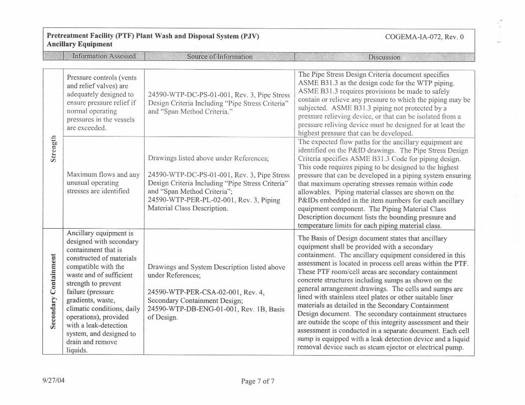
Pressure controls (vents and relief valves) are adequately designed to 24590-WTP-DC-PS-01-001, Rev. 3, Pipe Stress ensure pressure relief if Design Criteria Including "Pipe Stress Criteria" normal operating and "Span Method Criteria." pressures in the vessels are exceeded.
en C c.i I., .... Drawings listed above under References· (J) '
Maximum flows and any 24590-WTP-DC-PS-01-001, Rev. 3, Pipe Stress unusual operating Design Criteria Including "Pipe Stress Criteria" stresses are identified and "Span Method Criteria";
24590-WTP-PER-PL-02-001 , Rev. 3, Piping Material Class Description.
Ancillary equipment is designed with secondary containment that is .... constructed of materials = ~
s compatible with the Drawings and System Description listed above = waste and of sufficient ·; under References; ....
strength to prevent = 0 u failure (pressure 24590-WTP-PER-CSA-02-001, Rev. 4 , >. gradients, waste, Secondary Containment Design; -= climatic conditions, daily "C 24590-WTP-DB-ENG-01-001, Rev. IB, Basis = 0 operations), provided of Design. Cj ~ with a leak-detection (J)
system, and designed to drain and remove liquids.
9/27/04 Page 7 of7
COGEMA-IA-072, Rev. 0
7 Discussion
The Pipe Stress Design Criteria document specifies ASME B3 l .3 as the design code for the WTP piping. ASME B3 l .3 requires provisions be made to safely contain or relieve any pressure to which the piping may be subjected. ASME B31.3 piping not protected by a pressure relieving device, or that can be isolated from a pressure reliving device must be designed for at least the highest pressure that can be developed. The expected flow paths for the ancillary equipment are identified on the P&ID drawings. The Pipe Stress Design Crite1ia specifies ASME B31.3 Code for piping design. This code requires piping to be designed to the highest pressure that can be developed in a piping system ensuring that maximum operating stresses remain within code allowables. Piping material classes are shown on the P&~s embedded in the item numbers for each ancillary equipment component. The Piping Material Class Description document lists the bounding pressure and temperature limits for each piping material class.
The Basis of Design document states that ancillary equipment shall be provided with a secondary containment. The ancillary equipment considered in this assessment is located in process cell areas within the PTF. These PTF room/cell areas are secondary containment concrete structures including sumps as shown on the general arrangement drawings. The cells and sumps are lined with stainless steel plates or other suitable liner materials as detailed in the Secondary Containment Design document. The secondary containment structures are outside the scope of this integrity assessment and their assessment is conducted in a separate document. Each cell sump is equipped with a leak detection device and a liquid removal device such as steam ejector or electrical pump.


![MASTER SUBCONTRACT Agreement - Swinerton … Subcontract... · Web viewMASTER SUBCONTRACT Agreement THIS MASTER SUBCONTRACT AGREEMENT (“MSA” or “Agreement”) is made this [date]](https://img.pdfslide.us/doc/110x75/5adb1e4d7f8b9ae1768e1acc/master-subcontract-agreement-swinerton-subcontractweb-viewmaster-subcontract.jpg)