Embed Size (px)
Citation preview
Submittal Support
Table of Contents 1 Company Profile ........................................................................................................................................................................................................................................................................................................................................................................................................................................................ 1111
1.1 Awards............................................................................................................................. 2
2 Expanda Pipe Product Description ................................................................................................................................................................................................................................................................................................................................ 3333 2.1 The Product ..................................................................................................................... 3 2.2 Expanda PVC Profiles ..................................................................................................... 5 2.3 Expanda Pipe Applications.............................................................................................. 5
3 Expanda Features and Benefits........................................................................................................................................................................................................................................................................................................................................................ 8888 3.1 Speed of Installation ........................................................................................................ 8 3.2 Adaptability ...................................................................................................................... 9 3.3 Reduced Overpumping Costs ......................................................................................... 9 3.4 Hydraulic Efficiency ......................................................................................................... 9 3.5 Sealing the Pipeline .......................................................................................................10 3.6 Light Weight and Ease of Transportation ......................................................................10 3.7 Strength .........................................................................................................................10
4 Material Properties, Performance and Testing ................................................................................................................................................................................................................................................ 11111111 4.1 uPVC (Unplasticised Poly Vinyl Chloride) .....................................................................11 4.2 Sealing Materials ...........................................................................................................11 4.3 Chemical Resistance.....................................................................................................12 4.4 Abrasion Resistance......................................................................................................14
5 Structural Performance, Properties and Testing.................................................................................................................................................................................................................................... 15151515 5.1 Design Standards ..........................................................................................................15 5.2 Pipe Stiffness & Creep Ratio .........................................................................................15 5.3 Structural Testing ..........................................................................................................16
6 Sealing Performance, Properties and Testing .................................................................................................................................................................................................................................................... 18181818
7 Hydraulic Properties, Performance and Testing .................................................................................................................................................................................................................................... 19191919 7.1 Flow Coefficients ...........................................................................................................19 7.2 Flow Comparison...........................................................................................................20
8 Expanda Pipe Installation Method ................................................................................................................................................................................................................................................................................................................................ 24242424 8.1 The Installation Process ................................................................................................24 8.2 Installation Equipment ...................................................................................................26 8.3 Bends.............................................................................................................................27 8.4 Testing ...........................................................................................................................27
9 Expanda Pipe Approvals and References ........................................................................................................................................................................................................................................................................................................ 28282828 9.1 Australia ............................................................................................................................28 9.2 International ......................................................................................................................28
10. Rib Loc Quality System .................................................................................................................................................................................................................................................................................................................................................................................................................... 29292929
11. Environmental Impact ............................................................................................................................................................................................................................................................................................................................................................................................................................ 30303030

REH TEC EX 003 Expanda Submittal Support Document © Copyright Rib Loc Australia 2006
Page 1
1111 Company ProfileCompany ProfileCompany ProfileCompany Profile
Rib Loc Australia develops, manufactures and markets innovative pipe products, pipe machinery and pipeline rehabilitation technologies worldwide. Rib Loc is the developer and worldwide manufacturer of the unique, patented technologies Rotaloc®, Expanda™, Ribline™ and Ribsteel™. These plastic pipe products have been used around the world for the rehabilitation of deteriorated pipelines with minimal disruption. For new pipelines, Rib Loc has recently introduced Plastream, a steel reinforced plastic composite pipe used for drainage and sewer applications. In Australia, Rib Loc is one of the largest producers of plastic pipe products and was the first to commercialise Plastream in the pipe market. Since 1980, when Rib Loc was first established, a strong focus on innovation and development has led the company to continually improve and introduce new products, taking pipe technologies to the next generation. As a testimony to this, several prestigious worldwide awards have been presented to Rib Loc in recognition of its achievements in innovative pipe technologies. While its head office and main production site is located in Adelaide, Rib Loc also has sales and distribution centres in Melbourne, Sydney and Brisbane to cover Australia and an international office in Germany. Rib Loc employs 90 people worldwide and is now part of the global Chevalier Pipe Technologies Group. Other Rib Loc Business UnitsOther Rib Loc Business UnitsOther Rib Loc Business UnitsOther Rib Loc Business Units Pipe Products Rib Loc Pipe Products manufactures plastic pipes for the Australian market. The products manufactured are mainly for drainage and include pipe, fittings, subsurface drainage pipe and stormwater detention systems. In addition, Rib Loc Pipe Products also supplies the construction market with concrete column formwork. Plastream Plastream manufactures and supplies Plastream pipe production machinery, the next generation in pipe technologies, to anywhere in the world. Plastream is next generation as it is the first to develop a steel reinforced plastic pipe that offers the unique benefit of lower material costs for the same structural performance. Plastream pipes are suitable for non-pressure pipe applications including sewerage and drainage. Plastream offers a turnkey package which includes installation, commissioning, transfer of production know-how, technical and marketing assistance, and after-sales service. In addition, Plastream can offer you the experience of Rib Loc Pipe Products for invaluable insights into production, distribution, sales, marketing and pipe engineering.
REH TEC EX 003 Expanda Submittal Support Document © Copyright Rib Loc Australia 2006
Page 2
1.11.11.11.1 AwardsAwardsAwardsAwards
Rib Loc has been recognised by the industry for its engineering excellence through the achievement of a number of awards internationally. The prestigious international No-Dig Award has been awarded to Rib Loc twice, in recognition of its developments in the field of trenchless rehabilitation technologies. In 1997, Ribsteel™ achieved two awards for the Most Notable Technical Advancement by International Society for Trenchless Technology (ISTT) and the Engineering Excellence Award by the Australian Institute of Engineers. Similarly, Rotaloc achieved recognition as the Most Notable Technical Advancement in trenchless technologies by ISTT in 2001 and the Engineering Excellence Award from Engineers Australia in the category of innovation in 2000. Rotaloc also received the award for No-Dig Innovative Product in 2003 by the North American Society for Trenchless Technology.
REH TEC EX 003 Expanda Submittal Support Document © Copyright Rib Loc Australia 2006
Page 3
2222 Expanda Pipe Product DescriptionExpanda Pipe Product DescriptionExpanda Pipe Product DescriptionExpanda Pipe Product Description
2.12.12.12.1 The ProductThe ProductThe ProductThe Product
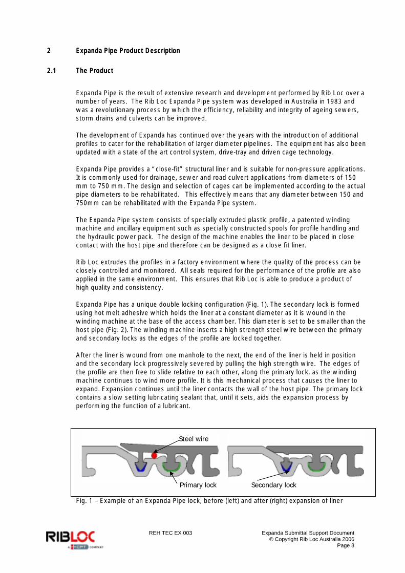
Expanda Pipe is the result of extensive research and development performed by Rib Loc over a number of years. The Rib Loc Expanda Pipe system was developed in Australia in 1983 and was a revolutionary process by which the efficiency, reliability and integrity of ageing sewers, storm drains and culverts can be improved. The development of Expanda has continued over the years with the introduction of additional profiles to cater for the rehabilitation of larger diameter pipelines. The equipment has also been updated with a state of the art control system, drive-tray and driven cage technology. Expanda Pipe provides a “close-fit” structural liner and is suitable for non-pressure applications. It is commonly used for drainage, sewer and road culvert applications from diameters of 150 mm to 750 mm. The design and selection of cages can be implemented according to the actual pipe diameters to be rehabilitated. This effectively means that any diameter between 150 and 750mm can be rehabilitated with the Expanda Pipe system. The Expanda Pipe system consists of specially extruded plastic profile, a patented winding machine and ancillary equipment such as specially constructed spools for profile handling and the hydraulic power pack. The design of the machine enables the liner to be placed in close contact with the host pipe and therefore can be designed as a close fit liner. Rib Loc extrudes the profiles in a factory environment where the quality of the process can be closely controlled and monitored. All seals required for the performance of the profile are also applied in the same environment. This ensures that Rib Loc is able to produce a product of high quality and consistency. Expanda Pipe has a unique double locking configuration (Fig. 1). The secondary lock is formed using hot melt adhesive which holds the liner at a constant diameter as it is wound in the winding machine at the base of the access chamber. This diameter is set to be smaller than the host pipe (Fig. 2). The winding machine inserts a high strength steel wire between the primary and secondary locks as the edges of the profile are locked together. After the liner is wound from one manhole to the next, the end of the liner is held in position and the secondary lock progressively severed by pulling the high strength wire. The edges of the profile are then free to slide relative to each other, along the primary lock, as the winding machine continues to wind more profile. It is this mechanical process that causes the liner to expand. Expansion continues until the liner contacts the wall of the host pipe. The primary lock contains a slow setting lubricating sealant that, until it sets, aids the expansion process by performing the function of a lubricant.
Fig. 1 – Example of an Expanda Pipe lock, before (left) and after (right) expansion of liner
Steel wire
Primary lock Secondary lock
REH TEC EX 003 Expanda Submittal Support Document © Copyright Rib Loc Australia 2006
Page 4
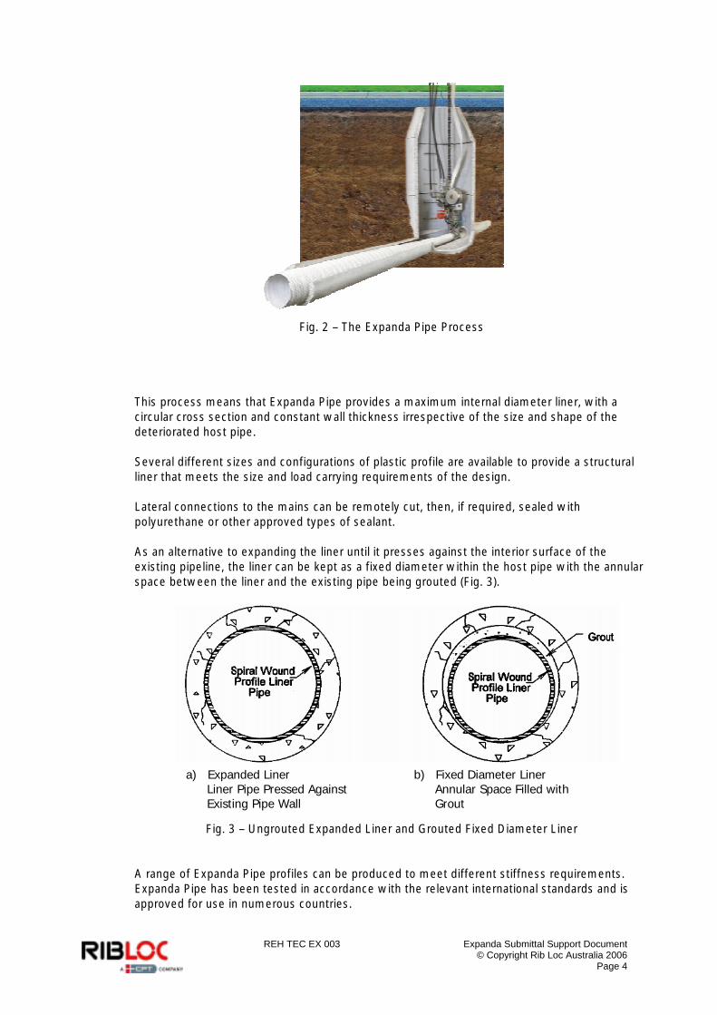
Fig. 2 – The Expanda Pipe Process
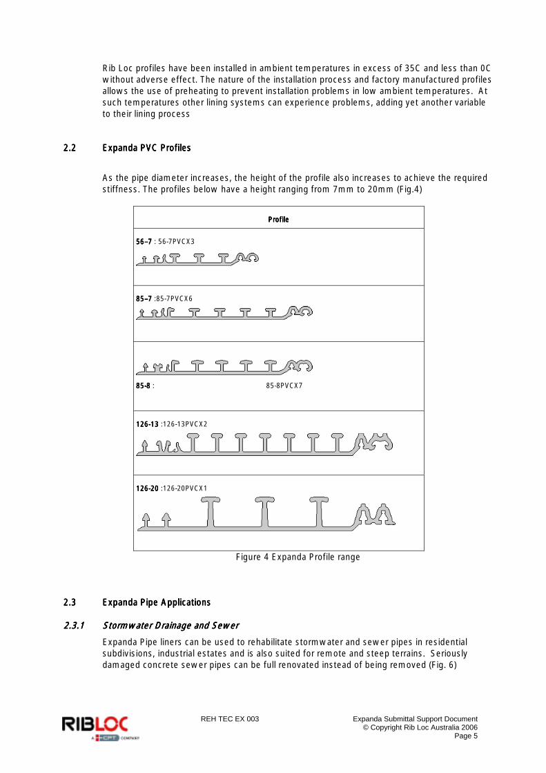
This process means that Expanda Pipe provides a maximum internal diameter liner, with a circular cross section and constant wall thickness irrespective of the size and shape of the deteriorated host pipe. Several different sizes and configurations of plastic profile are available to provide a structural liner that meets the size and load carrying requirements of the design. Lateral connections to the mains can be remotely cut, then, if required, sealed with polyurethane or other approved types of sealant. As an alternative to expanding the liner until it presses against the interior surface of the existing pipeline, the liner can be kept as a fixed diameter within the host pipe with the annular space between the liner and the existing pipe being grouted (Fig. 3).
Fig. 3 – Ungrouted Expanded Liner and Grouted Fixed Diameter Liner
A range of Expanda Pipe profiles can be produced to meet different stiffness requirements. Expanda Pipe has been tested in accordance with the relevant international standards and is approved for use in numerous countries.
a) Expanded Liner Liner Pipe Pressed Against Existing Pipe Wall
b) Fixed Diameter Liner Annular Space Filled with Grout
REH TEC EX 003 Expanda Submittal Support Document © Copyright Rib Loc Australia 2006
Page 5
Rib Loc profiles have been installed in ambient temperatures in excess of 35C and less than 0C without adverse effect. The nature of the installation process and factory manufactured profiles allows the use of preheating to prevent installation problems in low ambient temperatures. At such temperatures other lining systems can experience problems, adding yet another variable to their lining process
2.22.22.22.2 Expanda PExpanda PExpanda PExpanda PVC ProfilesVC ProfilesVC ProfilesVC Profiles
As the pipe diameter increases, the height of the profile also increases to achieve the required stiffness. The profiles below have a height ranging from 7mm to 20mm (Fig.4)
ProfileProfileProfileProfile
56565656––––7777 : 56-7PVCX3
85858585––––7777 :85-7PVCX6
85858585----8888 : 85-8PVCX7
126126126126----13131313 :126-13PVCX2
126126126126----20202020 :126-20PVCX1
Figure 4 Expanda Profile range
2.32.32.32.3 Expanda Pipe ApplicationsExpanda Pipe ApplicationsExpanda Pipe ApplicationsExpanda Pipe Applications
2.3.12.3.12.3.12.3.1 Stormwater Drainage and SewerStormwater Drainage and SewerStormwater Drainage and SewerStormwater Drainage and Sewer
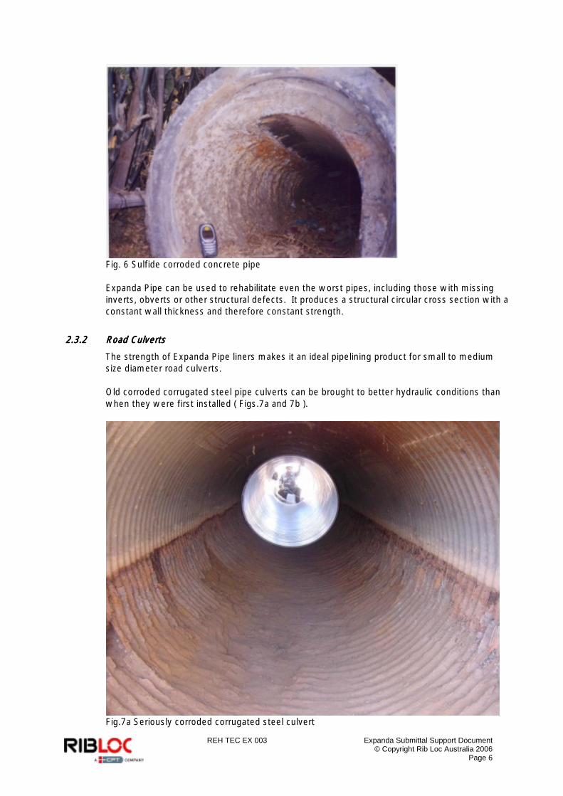
Expanda Pipe liners can be used to rehabilitate stormwater and sewer pipes in residential subdivisions, industrial estates and is also suited for remote and steep terrains. Seriously damaged concrete sewer pipes can be full renovated instead of being removed (Fig. 6)
REH TEC EX 003 Expanda Submittal Support Document © Copyright Rib Loc Australia 2006
Page 6
Fig. 6 Sulfide corroded concrete pipe Expanda Pipe can be used to rehabilitate even the worst pipes, including those with missing inverts, obverts or other structural defects. It produces a structural circular cross section with a constant wall thickness and therefore constant strength.
2.3.22.3.22.3.22.3.2 Road CulvertsRoad CulvertsRoad CulvertsRoad Culverts
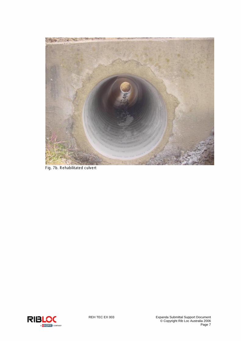
The strength of Expanda Pipe liners makes it an ideal pipelining product for small to medium size diameter road culverts. Old corroded corrugated steel pipe culverts can be brought to better hydraulic conditions than when they were first installed ( Figs.7a and 7b ).
Fig.7a Seriously corroded corrugated steel culvert
REH TEC EX 003 Expanda Submittal Support Document © Copyright Rib Loc Australia 2006
Page 7
Fig. 7b. Rehabilitated culvert
REH TEC EX 003 Expanda Submittal Support Document © Copyright Rib Loc Australia 2006
Page 8
3333 Expanda Features and BenefitsExpanda Features and BenefitsExpanda Features and BenefitsExpanda Features and Benefits
The two major benefits of Expanda Pipe are the low risk low risk low risk low risk and low costlow costlow costlow cost of installation. Low RiskLow RiskLow RiskLow Risk As diameters increase, the risk and consequence of failure of performing an installation with a Cured In Place product increases exponentially. This is because the mass of uncured resin increases proportionally. It is fair to say that as the diameters increase so does the risk. Expanda Pipe is the best solution for small to medium diameters because all the rehabilitation material is delivered to site in its final form. It has been produced in a factory environment according to tight quality controls. There are no risks associated with curing the material underground at the project site where the environment and conditions are uncontrollable. In addition, the process can be started and stopped as needed, should unexpected underground situations present themselves. Expanda Pipe is the clever solution being sought for the small to medium diameter market. Low CostLow CostLow CostLow Cost In addition to being low risk, Expanda Pipe materials and the installation process are low cost. The intelligent use of material in the design of the profiles provides for high strength to weight ratios and means far less material is used than a solid wall alternative. In addition to the principle benefits mentioned above, the Expanda Pipe relining system offers many other advantages, such as: o Speed of Installation o Adaptability o Reduced Overpumping Costs o Hydraulic Efficiency o Sealing the Pipeline o Lightweight & Ease of Transportation o Simple & Compact Machinery o Ease of Installation
3.13.13.13.1 Speed of InstallationSpeed of InstallationSpeed of InstallationSpeed of Installation
One of the key benefits of the Expanda Pipe system is the speed of installation. High installation speeds can be attained due to the fact that the majority of liner manufacture occurs in the factory and not on site as compared with many other systems available in the market. The profile is then installed into the deteriorated host pipe using a mechanical winding process rather than a chemical or heat process. The fact that the liner can be installed on site in a single, well controlled process ensures the exceptional speed and quality of installation. The time saving achieved with the Expanda Pipe system is not limited simply to the speed at which the liner is installed. As with all systems, the total time on site is critical to the cost effectiveness of a project. This includes time for mobilising, setting up, relocating to new lines, opening of laterals, cleaning up and demobilising. The Expanda Pipe system minimises the time spent on all of these operations. Support vehicles are kept to a minimum and as a result the Expanda Pipe system can be relocated and demobilised very rapidly. It can be expected that minimal preparatory work will
REH TEC EX 003 Expanda Submittal Support Document © Copyright Rib Loc Australia 2006
Page 9
be required within the access chamber . Typically this may involve the partial removal of benching in order to accommodate the winding cage. Where line lengths and orientations permit the Expanda Pipe liner can pass through successive access chambers without the need for repeated setting up.
3.23.23.23.2 AdaptabilityAdaptabilityAdaptabilityAdaptability
A pipeline in need of rehabilitation will not always be smooth and circular. Joints between successive pipes may be misaligned and sections may have collapsed leaving voids. Alternatively, some pipes may have already been subject to point repairs resulting in isolated changes in diameter. These problems result in a pipe of varying cross section and structural stability. Conventional close fit lining processes rely on the host pipe to provide an outer formwork against which the liner is formed. The Expanda Pipe system works by expanding the liner to become intimate to the host pipe. This enables the system to adapt to the site conditions and maximise cross-sectional area without compromising the design of the product. At locations where offset joints or local deflections have reduced the cross-section, the liner reduces in diameter but maximises the liner diameter through this section. On passing the local deflection the liner will expand to the size of the host pipe, returning to full size. Where pipe sections are missing the Expanda Pipe system spans the missing section leaving a circular cross-section and maximising flow conditions and structural strength. Where required by design, the void associated with the missing pipe section can be filled with grout from the surface or by using no-dig grouting techniques from within the liner.
3.33.33.33.3 RRRReduced Overpumping Costseduced Overpumping Costseduced Overpumping Costseduced Overpumping Costs
Conventional pipeline rehabilitation techniques require overpumping or bypassing of the flows, which is both disruptive and costly. In conditions of low pipe flow it is possible to use the Rib Loc system without overpumping. A stopper can be placed in the upstream manhole and the flow is allowed to back up for the duration of the liner installation. If some of the backed up sewage must be released during the course of installation, the sewage can be allowed to flow through the partially completed liner.
3.43.43.43.4 Hydraulic EfficiencyHydraulic EfficiencyHydraulic EfficiencyHydraulic Efficiency
An important consideration when evaluating any rehabilitation technique is the impact on flow capacity. As the Expanda Pipe system can install a liner which is in contact with the interior wall of the host pipe, it has the ability to minimise the loss in cross-sectional area. Coupled with the fact that the interior surface of the liner is typically hydraulically smoother than that of the host pipe, the capacity of the rehabilitated pipe will normally meet or exceed the existing capacity of the pipe. In cases where successive pipe lengths are out of alignment, a liner pipe will reduce turbulence and reduce the risk of blockages by providing a smooth continuous pipe from access chamber to access chamber. Hydraulic performance of Expanda Pipe liners is discussed in Section 7.
REH TEC EX 003 Expanda Submittal Support Document © Copyright Rib Loc Australia 2006
Page 10
3.53.53.53.5 Sealing the PipelineSealing the PipelineSealing the PipelineSealing the Pipeline
Two of the major concerns with deteriorated pipelines are infiltration of ground water into the pipe and exfiltration of flow into aquifers or ground water. Infiltration of groundwater into the pipeline increases the volume of flow which needs to be treated. Infiltration of highly saline groundwater can cause problems with the treatment of sewer flow and affect the quality of reclaimed water. The increased volume of water flowing through the pipeline can result in the flow treatment plant becoming overloaded. Infiltration of groundwater into the pipeline also erodes the backfill material. Extensive migration of the backfill material can lead to catastrophic failures at the ground surface. Exfiltration of flow from the pipeline into the surrounding soil pollutes the soil and the groundwater. In areas which rely on groundwater as a water supply there are serious health implications. The excellent sealing performance of Expanda Pipe liners means these problems can be solved. The sealing performance is discussed in more detail in Section 6.
3.3.3.3.6666 Light Weight and Ease of TransportationLight Weight and Ease of TransportationLight Weight and Ease of TransportationLight Weight and Ease of Transportation
The Expanda Pipe system manufactures the pipes on site and not in a factory. The plastic profile is supplied already extruded on spools. Typically when transporting pipes the majority of the load is air, therefore a wound in place option such as this dramatically reduces transport requirements.
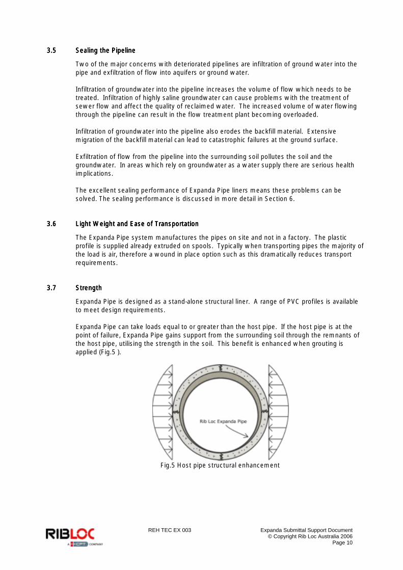
3.73.73.73.7 StrengthStrengthStrengthStrength
Expanda Pipe is designed as a stand-alone structural liner. A range of PVC profiles is available to meet design requirements. Expanda Pipe can take loads equal to or greater than the host pipe. If the host pipe is at the point of failure, Expanda Pipe gains support from the surrounding soil through the remnants of the host pipe, utilising the strength in the soil. This benefit is enhanced when grouting is applied (Fig.5 ).
Fig.5 Host pipe structural enhancement
REH TEC EX 003 Expanda Submittal Support Document © Copyright Rib Loc Australia 2006
Page 11
4444 Material Properties, Performance and TestingMaterial Properties, Performance and TestingMaterial Properties, Performance and TestingMaterial Properties, Performance and Testing
4.14.14.14.1 uPVC (Unplasticised Poly ViuPVC (Unplasticised Poly ViuPVC (Unplasticised Poly ViuPVC (Unplasticised Poly Vinyl Chloride) nyl Chloride) nyl Chloride) nyl Chloride)
4.1.14.1.14.1.14.1.1 PVC ResinPVC ResinPVC ResinPVC Resin
The PVC resin used in the production of Rib Loc’s Expanda Pipe profiles is unplasticised Poly Vinyl Chloride (uPVC), which is manufactured by Australian Vinyls, Mentone, Victoria. The type of resin is “K67”. The K value relates to the particle size of the resin. The cell class of the resin is 13354. uPVC is made by many manufacturers in many countries. The specification of this resin is typical of that produced worldwide. Refer to Appendices A and B for Technical Data Sheets and Material Safety Data Sheets.
4.1.24.1.24.1.24.1.2 PVC AdditivesPVC AdditivesPVC AdditivesPVC Additives
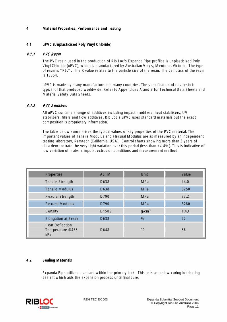
All uPVC contains a range of additives including impact modifiers, heat stabilisers, UV stabilisers, fillers and flow additives. Rib Loc’s uPVC uses standard materials but the exact composition is proprietary information. The table below summarises the typical values of key properties of the PVC material. The important values of Tensile Modulus and Flexural Modulus are as measured by an independent testing laboratory, Ramtech (California, USA). Control charts showing more than 3 years of data demonstrate the very tight variation over this period (less than +/- 4%). This is indicative of low variation of material inputs, extrusion conditions and measurement method.
4.24.24.24.2 Sealing MaterialsSealing MaterialsSealing MaterialsSealing Materials
Expanda Pipe utilises a sealant within the primary lock. This acts as a slow curing lubricating sealant which aids the expansion process until final cure.
Properties ASTM Unit Value
Tensile Strength D638 MPa 44.0
Tensile Modulus D638 MPa 3250
Flexural Strength D790 MPa 77.2
Flexural Modulus D790 MPa 3280
Density D1505 g/cm3 1.43
Elongation at Break D638 % 22
Heat Deflection Temperature @455 kPa
D648 °C 86
REH TEC EX 003 Expanda Submittal Support Document © Copyright Rib Loc Australia 2006
Page 12
4.34.34.34.3 Chemical ResistanceChemical ResistanceChemical ResistanceChemical Resistance
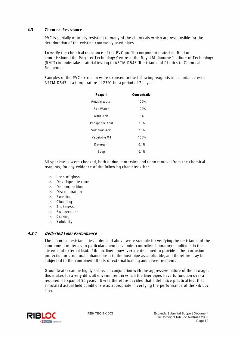
PVC is partially or totally resistant to many of the chemicals which are responsible for the deterioration of the existing commonly used pipes. To verify the chemical resistance of the PVC profile component materials, Rib Loc commissioned the Polymer Technology Centre at the Royal Melbourne Institute of Technology (RMIT) to undertake material testing to ASTM D543 ‘Resistance of Plastics to Chemical Reagents’. Samples of the PVC extrusion were exposed to the following reagents in accordance with ASTM D543 at a temperature of 23°C for a period of 7 days.
ReagentReagentReagentReagent ConcentrationConcentrationConcentrationConcentration
Potable Water 100%
Sea Water 100%
Nitric Acid 5%
Phosphoric Acid 10%
Sulphuric Acid 10%
Vegetable Oil 100%
Detergent 0.1%
Soap 0.1%
All specimens were checked, both during immersion and upon removal from the chemical reagents, for any evidence of the following characteristics: o Loss of gloss o Developed texture o Decomposition o Discolouration o Swelling o Clouding o Tackiness o Rubberiness o Crazing o Solubility
4.3.14.3.14.3.14.3.1 Deflected Liner PerformanceDeflected Liner PerformanceDeflected Liner PerformanceDeflected Liner Performance
The chemical resistance tests detailed above were suitable for verifying the resistance of the component materials to particular chemicals under controlled laboratory conditions in the absence of external load. Rib Loc liners however are designed to provide either corrosion protection or structural enhancement to the host pipe as applicable, and therefore may be subjected to the combined effects of external loading and sewer reagents. Groundwater can be highly saline. In conjunction with the aggressive nature of the sewage, this makes for a very difficult environment in which the liner pipes have to function over a required life span of 50 years. It was therefore decided that a definitive practical test that simulated actual field conditions was appropriate in verifying the performance of the Rib Loc liner.
REH TEC EX 003 Expanda Submittal Support Document © Copyright Rib Loc Australia 2006
Page 13
4.3.24.3.24.3.24.3.2 Testing ProcedureTesting ProcedureTesting ProcedureTesting Procedure
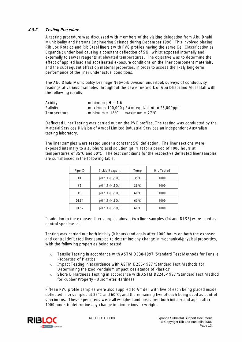
A testing procedure was discussed with members of the visiting delegation from Abu Dhabi Municipality and Parsons Engineering Science during December 1996. This involved placing Rib Loc Rotaloc and Rib Steel liners ( with PVC profiles having the same Cell Classification as Expanda ) under load causing a constant deflection of 5%, whilst exposed internally and externally to sewer reagents at elevated temperatures. The objective was to determine the effect of applied load and accelerated exposure conditions on the liner component materials, and the subsequent effect on material properties, in order to assess the likely long-term performance of the liner under actual conditions. The Abu Dhabi Municipality Drainage Network Division undertook surveys of conductivity readings at various manholes throughout the sewer network of Abu Dhabi and Mussafah with the following results: Acidity - minimum pH = 1.6 Salinity - maximum 100,000 µS/cm equivalent to 25,000ppm Temperature - minimum = 18°C maximum = 27°C Deflected Liner Testing was carried out on the PVC profiles. The testing was conducted by the Material Services Division of Amdel Limited Industrial Services an independent Australian testing laboratory. The liner samples were tested under a constant 5% deflection. The liner sections were exposed internally to a sulphuric acid solution (pH 1.1) for a period of 1000 hours at temperatures of 35°C and 60°C. The test conditions for the respective deflected liner samples are summarised in the following table:
Pipe ID Inside Reagent Temp Hrs Tested
#1 pH 1.1 (H2SO4) 35°C 1000
#2 pH 1.1 (H2SO4) 35°C 1000
#3 pH 1.1 (H2SO4) 60°C 1000
DLS1 pH 1.1 (H2SO4) 60°C 1000
DLS2 pH 1.1 (H2SO4) 60°C 1000
In addition to the exposed liner samples above, two liner samples (#4 and DLS3) were used as control specimens. Testing was carried out both initially (0 hours) and again after 1000 hours on both the exposed and control deflected liner samples to determine any change in mechanical/physical properties, with the following properties being tested: o Tensile Testing in accordance with ASTM D638-1997 ‘Standard Test Methods for Tensile
Properties of Plastics’ o Impact Testing in accordance with ASTM D256-1997 ‘Standard Test Methods for
Determining the Izod Pendulum Impact Resistance of Plastics’ o Shore D Hardness Testing in accordance with ASTM D2240-1997 ‘Standard Test Method
for Rubber Property - Durometer Hardness’ Fifteen PVC profile samples were also supplied to Amdel, with five of each being placed inside deflected liner samples at 35°C and 60°C, and the remaining five of each being used as control specimens. These specimens were all weighed and measured both initially and again after 1000 hours to determine any change in dimensions or weight.

REH TEC EX 003 Expanda Submittal Support Document © Copyright Rib Loc Australia 2006
Page 14
The mechanical/physical properties obtained for the deflected liner samples exposed internally to sulphuric acid (pH 1.1) at elevated temperatures for a period of 1000 hours were then compared to those obtained for the unexposed control liner samples. The results conclusively prove that these conditions had no detrimental effect on the deflected liner samples.
4.44.44.44.4 Abrasion Resistance Abrasion Resistance Abrasion Resistance Abrasion Resistance
Plastic has a far higher abrasion threshold than many other pipe materials such as concrete or clay. Below this abrasion threshold damage does not occur. In abrasion testing the pipe materials are generally subjected to much more severe conditions than in ordinary stormwater or sewer applications to ensure that damage does occur. In this way the relative performance of the various materials can be obtained.
4.4.14.4.14.4.14.4.1 NorthNorthNorthNorth----Rhine WestphaRhine WestphaRhine WestphaRhine Westphalia, Dortmund, Germanylia, Dortmund, Germanylia, Dortmund, Germanylia, Dortmund, Germany
A series of tests was undertaken at the State Materials Testing Bureau in North-Rhine Westphalia, Dortmund, Germany, in order to gain a Certificate of Approval for the Rib Loc Lining System. Three tests were carried out, namely: o Abrasion by means of a gravity chute in accordance with DIN 1230 Part 2 o Behaviour under cold impact load at 0°C o Behaviour under external water overpressure (short and long-term loading)
The results of the tests indicated that the Rib Loc Lining System met the requirements with regards to resistance against mechanical stress and behaviour under abrasion.
4.4.24.4.24.4.24.4.2 Duncan Tool and Gauge Pty LtdDuncan Tool and Gauge Pty LtdDuncan Tool and Gauge Pty LtdDuncan Tool and Gauge Pty Ltd
In order to verify the performance of a uPVC liner in a sewer environment, Rib Loc coordinated the removal of two samples from a liner installed in 1990. The 300mm diameter sewer was lined as a trial with the Engineering and Water Supply Department in South Australia. This particular line was chosen for the trial due to excessive infiltration of saline groundwater and sand. Infiltration is still a problem with upstream sewers. This has resulted in large amounts of sand being transported by the sewer. Of the two samples removed, one was from the crown of the pipe and the other from the invert. By comparing the wall thicknesses of the two samples, the abrasion of the invert could be quantified. A series of measurements was taken at the National Association of Testing Authorities Australia accredited laboratory of Duncan Tool and Gauge Pty Ltd. The mean thicknesses from the invert and crown samples varied by no more than 0.003mm or 0.1%. As the uncertainty of measurement is 0.004mm, it can be concluded that no measurable abrasion has taken place.

REH TEC EX 003 Expanda Submittal Support Document © Copyright Rib Loc Australia 2006
Page 15
5555 Structural Performance, Properties and TestingStructural Performance, Properties and TestingStructural Performance, Properties and TestingStructural Performance, Properties and Testing
Expanda Pipe is designed to perform as a stand alone structural liner to withstand the following loads: o Earth loads o Live loads due to traffic o Hydrostatic loads
This section presents the design methodologies and the important structural performance data and tests.
5.15.15.15.1 Design StandardsDesign StandardsDesign StandardsDesign Standards
There are several internationally applicable design standards. Three of the more commonly used standards are ASASASASTM F1741, AS/NZS 2566, ATVTM F1741, AS/NZS 2566, ATVTM F1741, AS/NZS 2566, ATVTM F1741, AS/NZS 2566, ATV----DVWKDVWKDVWKDVWK----MMMM 127 E. 127 E. 127 E. 127 E. In each of these standards the important input data is the Long Term Stiffness (and Enhancement Factor in the case of the Partially Deteriorated design). These values are shown for Expanda Pipe in the tables in section 5.2.
5.25.25.25.2 Pipe Stiffness & Pipe Stiffness & Pipe Stiffness & Pipe Stiffness & Creep RatioCreep RatioCreep RatioCreep Ratio
Five Expanda Pipe profiles are used to cover the diameter range 150mm to 750mm. The tables below show the important structural information for these profiles as a function of diameter. 56-7 Profile
Host Diameter
Internal Diameter of Expanda Pipe
Liner
Nominal Ring
Stiffness
Long Term Nominal
Ring Stiffness
Pipe Stiffness
Long Term Pipe
Stiffness
Creep Ratio
Enhancement Factor
mm mm in. N/m/m N/m/m psi psi (50yr)
150 136.5 5.4 9058 4419 70.6 34.4 2.05 4
200 186.5 7.3 4157 2028 32.4 15.8 2.05 4
85-7 Profile
Host Diameter
Internal Diameter of
Expanda Pipe Liner
Nominal Ring
Stiffness
Long Term Nominal
Ring Stiffness
Pipe Stiffness
Long Term Pipe
Stiffness
Creep Ratio
Enhancement Factor
mm mm in. N/m/m N/m/m psi psi (50 yr)
150 136.4 5.4 8716 4252 67.9 33.1 2.05 4
225 211.4 8.3 2904 1417 22.6 11.0 2.05 4
250 236.4 9.3 2159 1053 16.8 8.2 2.05 4
300 286.4 11.3 1284 626 10.0 4.9 2.05 4

REH TEC EX 003 Expanda Submittal Support Document © Copyright Rib Loc Australia 2006
Page 16
85-8 Profile
Host Diameter
Internal Diameter of
Expanda Pipe Liner
Nominal Ring
Stiffness
Long Term Nominal
Ring Stiffness
Pipe Stiffness
Long Term Pipe
Stiffness
Creep Ratio
Enhancement Factor
mm mm in. N/m/m N/m/m psi psi (50 yr)
200 183 7.2 6666 3252 51.9 25.3 2.05 4
225 208 8.2 4928 2404 38.4 18.7 2.05 4
250 233 9.2 3729 1819 29.0 14.2 2.05 4
300 283 11.1 2270 1107 17.7 8.6 2.05 4
126-13Ex Profile
Host Diameter
Internal Diameter of Expanda Pipe
Liner
Nominal Ring
Stiffness
Long Term Nominal
Ring Stiffness
Pipe Stiffness
Long Term Pipe
Stiffness
Creep Ratio
Enhancement Factor
mm mm in. N/m/m N/m/m psi psi (50 yr)
300 273.5 10.8 6688 3262 52.1 25.4 2.05 4
375 348.5 13.7 3682 1796 28.7 14.0 2.05 4
450 423.5 16.7 2221 1084 17.3 8.4 2.05 4
525 498.5 19.6 1437 701 11.2 5.5 2.05 4
600 573.5 22.6 981 478 7.6 3.7 2.05 4
126-20Ex Profile
Host Diameter
Internal Diameter of Expanda Pipe
Liner
Nominal Ring
Stiffness
Long Term Nominal
Ring Stiffness
Pipe Stiffness
Long Term Pipe
Stiffness
Creep Ratio
Enhancement Factor
mm mm in. N/m/m N/m/m psi psi (50 yr)
450 410 16.1 4870 2376 37.9 18.5 2.05 4
525 485 19.1 3263 1592 25.4 12.4 2.05 4
600 560 22.0 2277 1111 17.7 8.7 2.05 4
675 635 25.0 1646 803 12.8 6.3 2.05 4
750 710 28.0 1226 598 9.5 4.7 2.05 4
5.35.35.35.3 Structural TestingStructural TestingStructural TestingStructural Testing
The following structural tests have been performed on Expanda Pipe liners and profiles. Testing was conducted in-house by Rib Loc Australia Pty Ltd.
5.3.15.3.15.3.15.3.1 Ring StiffnessRing StiffnessRing StiffnessRing Stiffness: EN IS: EN IS: EN IS: EN ISO 9969 Thermoplastics Pipes O 9969 Thermoplastics Pipes O 9969 Thermoplastics Pipes O 9969 Thermoplastics Pipes Determination of Ring StiffnessDetermination of Ring StiffnessDetermination of Ring StiffnessDetermination of Ring Stiffness
This strength test requires an external load to be applied to the pipe at a constant rate to achieve a deflection. The load and deflection are used to calculate ring stiffness.

REH TEC EX 003 Expanda Submittal Support Document © Copyright Rib Loc Australia 2006
Page 17
5.3.25.3.25.3.25.3.2 Creep Ratio: EN ISO 9967 Determination of CrCreep Ratio: EN ISO 9967 Determination of CrCreep Ratio: EN ISO 9967 Determination of CrCreep Ratio: EN ISO 9967 Determination of Creep Ratioeep Ratioeep Ratioeep Ratio
The Creep Test involves applying a constant load to the pipe for a period of 1000 hours. The initial load is determined as being that that is required to deflect the pipe initially by 1.5%. During the 1000 hours the deflection is measured and from this data long-term creep curves are generated which are used to predict the deflection of the pipe over its lifetime. The ratio of the short-term strength over the long-term strength is defined as the creep ratio.
5.3.35.3.35.3.35.3.3 Enhancement FactorEnhancement FactorEnhancement FactorEnhancement Factor
The enhancement factor test looks to determine the pressure required to buckle the liner when it is in contact with the host pipe. This pressure divided by the unsupported buckling pressure is defined as the enhancement factor. It is an important design parameter in the case of close fit liners. Theoretical models for enhancement factor (cited in Buckling Models and Influencing Factors for Pipe Rehabilitation Design, Leslie K. Guice and J.Y. Li, Louisiana Tech University) and testing undertaken by Rib Loc to date advocate the use of a minimum value of 4 for enhancement factor for Expanda profiles. When simplifying the theory the end result becomes
ItDEF.24
2.28.0
=
Where: D = diameter (mm) t = effective thickness, 2 x depth to neutral axis of profile (mm) I = unit second moment of area (mm4/mm)
This theory demonstrates that increases of enhancement factor can be expected at larger diameters. Theoretical results have proven higher than empirical testing has shown in the past. When this has been taken into account, enhancement values of 4 have been shown to be conservative at the minimum diameters at which Expanda profiles are used.
REH TEC EX 003 Expanda Submittal Support Document © Copyright Rib Loc Australia 2006
Page 18
6666 Sealing Performance, Properties and TestingSealing Performance, Properties and TestingSealing Performance, Properties and TestingSealing Performance, Properties and Testing
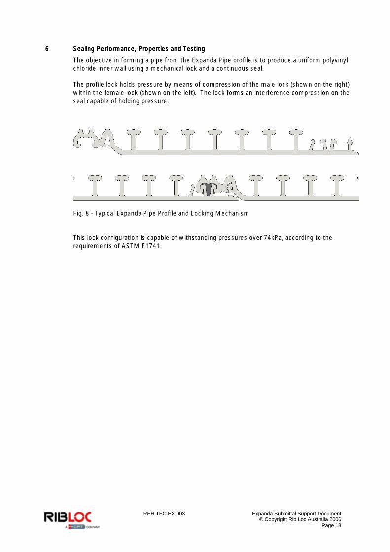
The objective in forming a pipe from the Expanda Pipe profile is to produce a uniform polyvinyl chloride inner wall using a mechanical lock and a continuous seal. The profile lock holds pressure by means of compression of the male lock (shown on the right) within the female lock (shown on the left). The lock forms an interference compression on the seal capable of holding pressure.
Fig. 8 - Typical Expanda Pipe Profile and Locking Mechanism This lock configuration is capable of withstanding pressures over 74kPa, according to the requirements of ASTM F1741.
REH TEC EX 003 Expanda Submittal Support Document © Copyright Rib Loc Australia 2006
Page 19
7777 Hydraulic Properties, PerformaHydraulic Properties, PerformaHydraulic Properties, PerformaHydraulic Properties, Performance and Testingnce and Testingnce and Testingnce and Testing
7.17.17.17.1 Flow CoefficientsFlow CoefficientsFlow CoefficientsFlow Coefficients
The surface roughness of PVC is generally considered to be one of the lowest of the pipe materials. This can be quantified in a number of ways and is shown in the table below. Testing was carried out by Techsearch at the University of South Australia in May 1991, to determine fluid friction loss coefficients and pipe wall roughness parameters, etc. required for application in:
a. Manning’s equation b. Colebrook White equation c. Hazen Williams equation
Test results indicated a Manning's coefficient of between 0.0080 and 0.0094 for Rib Loc pipe.
Mannings n 0.009
Colebrook White k 0.015mm
Hazen Williams C 143
Mannings formulaMannings formulaMannings formulaMannings formula
21
321 SAR
nQ =
Where: n = Manning’s number Q = flow (m3/s) A = area (m2) R = hydraulic radius (Area/ Perimeter) S = slope of the line, hydraulic gradient (m/m) Colebrook White FormulaColebrook White FormulaColebrook White FormulaColebrook White Formula
2
10
2
251.2
7.3
log24
+=
gDSk
DgDSDQ υπ
Where: S = slope of the line, hydraulic gradient (m/m) f = Darcy-Weisbach friction factor k = Roughness (m) D = Diameter g = gravitational acceleration (9.81 m/s2) ν = Kinematic viscosity of water (m2/s) Hazen Williams FormulaHazen Williams FormulaHazen Williams FormulaHazen Williams Formula
( ) 54.063.0849.0 SCARQ = Where: A = area (m2) C = Hazen Williams roughness coefficient R = hydraulic radius (Area/Perimeter) S = slope of the line, hydraulic gradient (m/m)
REH TEC EX 003 Expanda Submittal Support Document © Copyright Rib Loc Australia 2006
Page 20
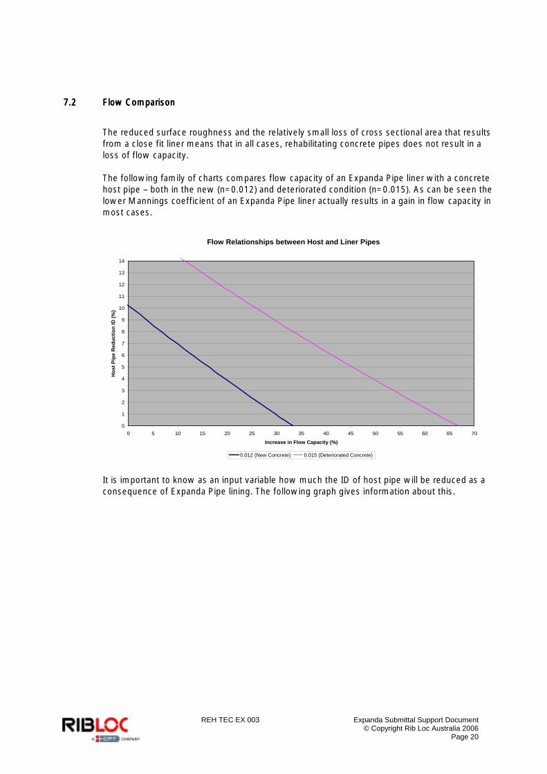
7.27.27.27.2 Flow ComparisonFlow ComparisonFlow ComparisonFlow Comparison
The reduced surface roughness and the relatively small loss of cross sectional area that results from a close fit liner means that in all cases, rehabilitating concrete pipes does not result in a loss of flow capacity. The following family of charts compares flow capacity of an Expanda Pipe liner with a concrete host pipe – both in the new (n=0.012) and deteriorated condition (n=0.015). As can be seen the lower Mannings coefficient of an Expanda Pipe liner actually results in a gain in flow capacity in most cases.
Flow Relationships between Host and Liner Pipes
0
1
2
3
4
5
6
7
8
9
10
11
12
13
14
0 5 10 15 20 25 30 35 40 45 50 55 60 65 70
Increase in Flow Capacity (%)
Hos
t Pip
e R
educ
tion
ID (%
)
0.012 (New Concrete) 0.015 (Deteriorated Concrete)
It is important to know as an input variable how much the ID of host pipe will be reduced as a consequence of Expanda Pipe lining. The following graph gives information about this.
REH TEC EX 003 Expanda Submittal Support Document © Copyright Rib Loc Australia 2006
Page 21
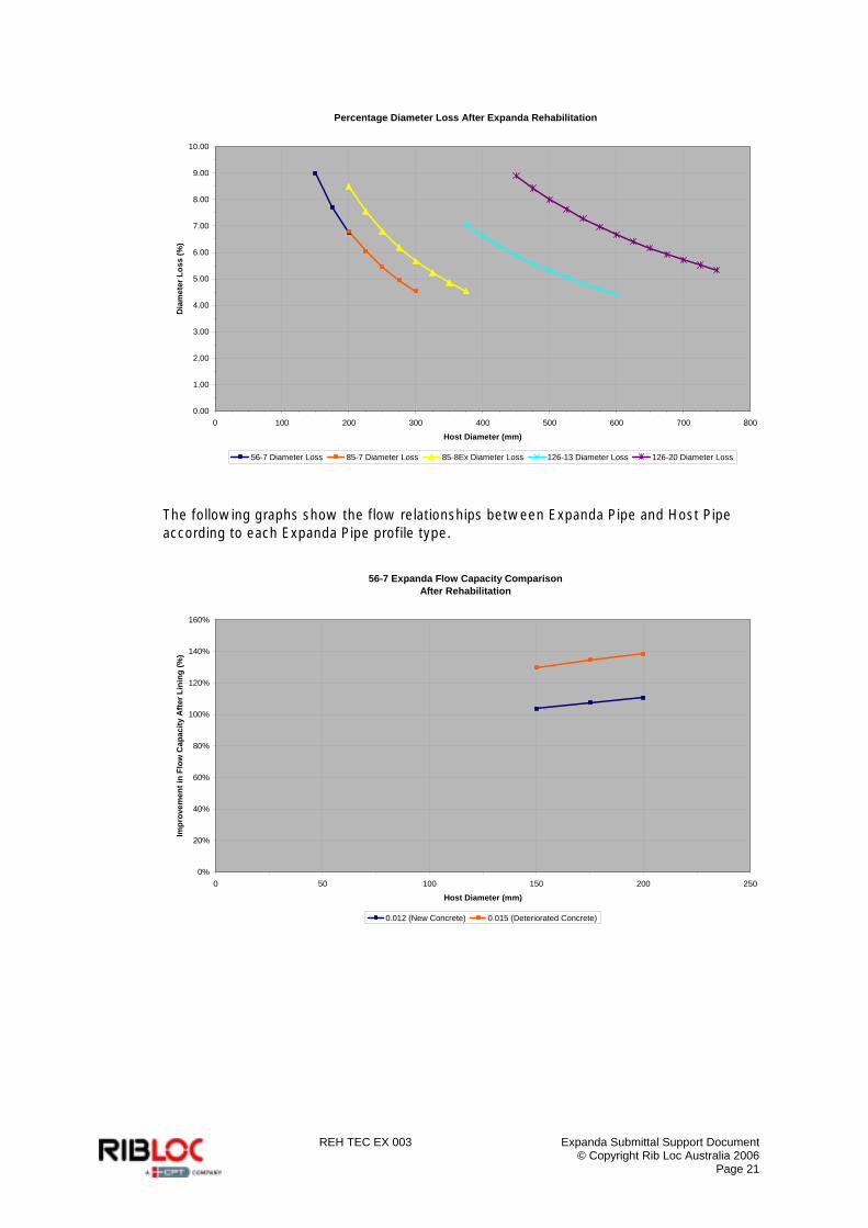
Percentage Diameter Loss After Expanda Rehabilitation
0.00
1.00
2.00
3.00
4.00
5.00
6.00
7.00
8.00
9.00
10.00
0 100 200 300 400 500 600 700 800
Host Diameter (mm)
Dia
met
er L
oss
(%)
56-7 Diameter Loss 85-7 Diameter Loss 85-8Ex Diameter Loss 126-13 Diameter Loss 126-20 Diameter Loss
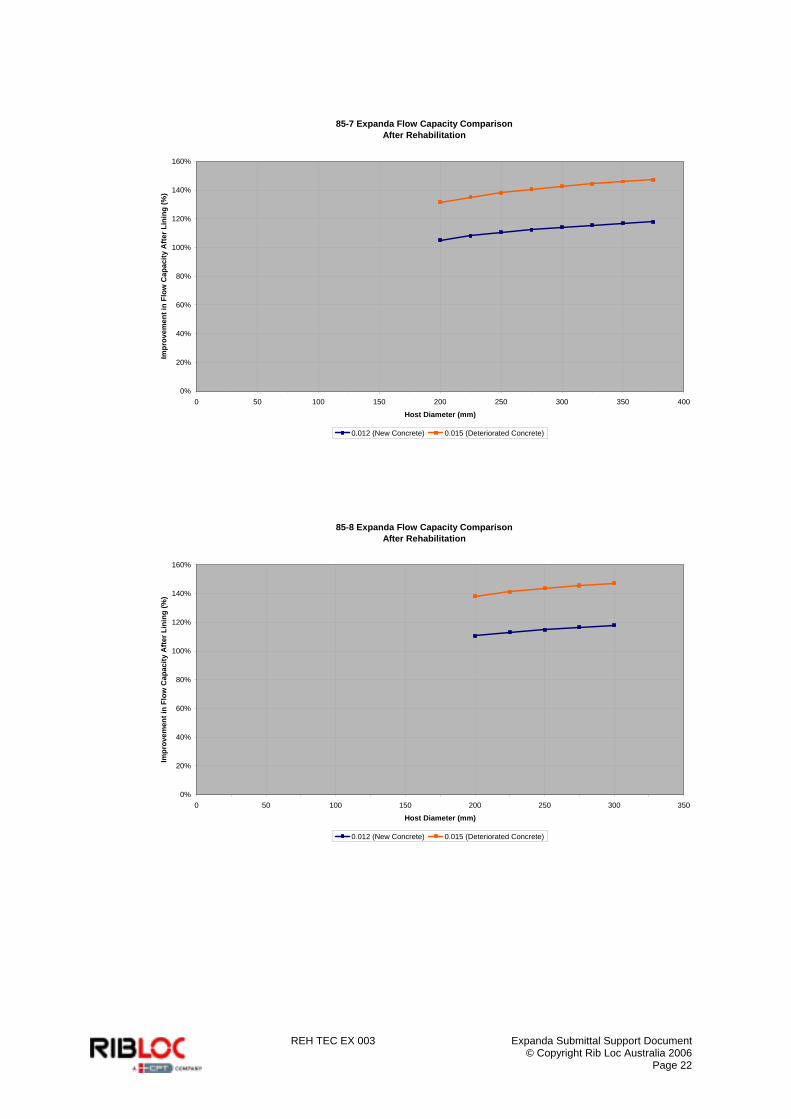
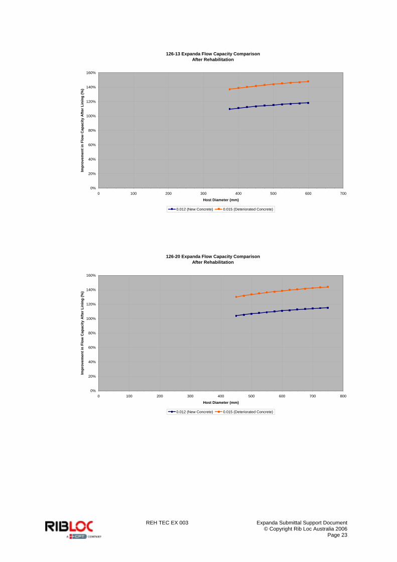
The following graphs show the flow relationships between Expanda Pipe and Host Pipe according to each Expanda Pipe profile type.
56-7 Expanda Flow Capacity ComparisonAfter Rehabilitation
0%
20%
40%
60%
80%
100%
120%
140%
160%
0 50 100 150 200 250
Host Diameter (mm)
Impr
ovem
ent i
n Fl
ow C
apac
ity A
fter L
inin
g (%
)
0.012 (New Concrete) 0.015 (Deteriorated Concrete)
REH TEC EX 003 Expanda Submittal Support Document © Copyright Rib Loc Australia 2006
Page 22
85-7 Expanda Flow Capacity ComparisonAfter Rehabilitation
0%
20%
40%
60%
80%
100%
120%
140%
160%
0 50 100 150 200 250 300 350 400
Host Diameter (mm)
Impr
ovem
ent i
n Fl
ow C
apac
ity A
fter L
inin
g (%
)
0.012 (New Concrete) 0.015 (Deteriorated Concrete)
85-8 Expanda Flow Capacity ComparisonAfter Rehabilitation
0%
20%
40%
60%
80%
100%
120%
140%
160%
0 50 100 150 200 250 300 350
Host Diameter (mm)
Impr
ovem
ent i
n Fl
ow C
apac
ity A
fter L
inin
g (%
)
0.012 (New Concrete) 0.015 (Deteriorated Concrete)
REH TEC EX 003 Expanda Submittal Support Document © Copyright Rib Loc Australia 2006
Page 23
126-13 Expanda Flow Capacity ComparisonAfter Rehabilitation
0%
20%
40%
60%
80%
100%
120%
140%
160%
0 100 200 300 400 500 600 700
Host Diameter (mm)
Impr
ovem
ent i
n Fl
ow C
apac
ity A
fter L
inin
g (%
)
0.012 (New Concrete) 0.015 (Deteriorated Concrete)
126-20 Expanda Flow Capacity ComparisonAfter Rehabilitation
0%
20%
40%
60%
80%
100%
120%
140%
160%
0 100 200 300 400 500 600 700 800
Host Diameter (mm)
Impr
ovem
ent i
n Fl
ow C
apac
ity A
fter L
inin
g (%
)
0.012 (New Concrete) 0.015 (Deteriorated Concrete)
REH TEC EX 003 Expanda Submittal Support Document © Copyright Rib Loc Australia 2006
Page 24
8888 EEEExpanda Pipe Installation Methodxpanda Pipe Installation Methodxpanda Pipe Installation Methodxpanda Pipe Installation Method
The system can generally be installed in accordance with ASTM F1741 “Standard Practice for Installation of Spiral Wound PVC Liner Pipe for Rehabilitation of Existing Sewers and Conduits”. Prior to actual pipe cleaning surveying and lining the contractor will normally carry out the following activities: o Obtaining necessary approvals and permits, implementation of approved traffic and
pedestrian control measures as required. o Isolation of the sewer section and establishment of overpumping equipment if required
(normally not required for Expanda Pipe). A typical Expanda Pipe winding crew would consist of 4 trained people as follows: o Control panel operator o Spool operator o Machine operator (at the access chamber) o Support operator at the far end access chamber o A part time Supervisor is also normally required on site
8.18.18.18.1 The Installation ProcessThe Installation ProcessThe Installation ProcessThe Installation Process
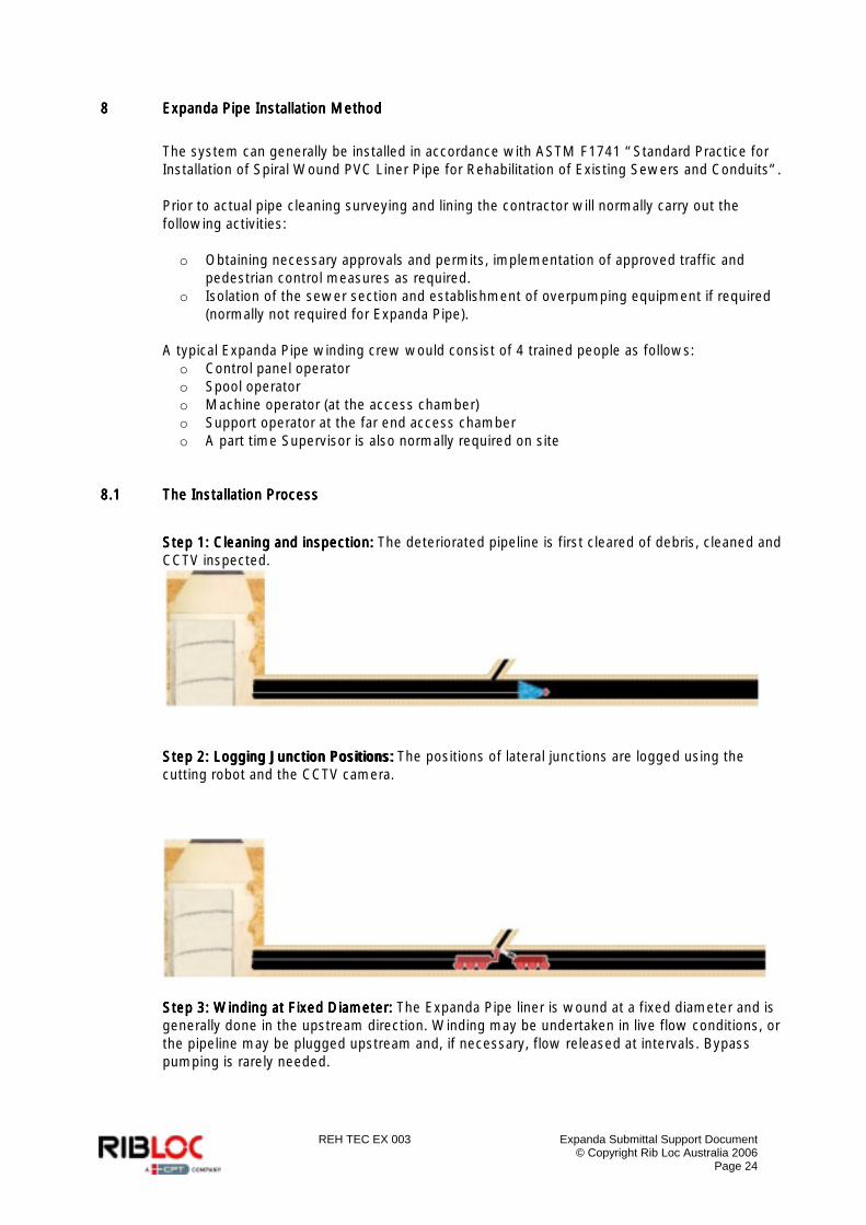
Step 1: Cleaning and inspection:Step 1: Cleaning and inspection:Step 1: Cleaning and inspection:Step 1: Cleaning and inspection: The deteriorated pipeline is first cleared of debris, cleaned and CCTV inspected.
Step 2: Logging Junction Positions: Step 2: Logging Junction Positions: Step 2: Logging Junction Positions: Step 2: Logging Junction Positions: The positions of lateral junctions are logged using the cutting robot and the CCTV camera.
SteSteSteStep 3: Winding at Fixed Diameter:p 3: Winding at Fixed Diameter:p 3: Winding at Fixed Diameter:p 3: Winding at Fixed Diameter: The Expanda Pipe liner is wound at a fixed diameter and is generally done in the upstream direction. Winding may be undertaken in live flow conditions, or the pipeline may be plugged upstream and, if necessary, flow released at intervals. Bypass pumping is rarely needed.
REH TEC EX 003 Expanda Submittal Support Document © Copyright Rib Loc Australia 2006
Page 25
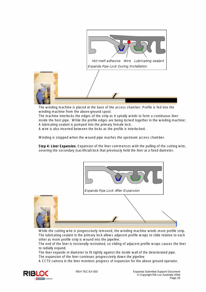
The winding machine is placed at the base of the access chamber. Profile is fed into the winding machine from the above-ground spool. The machine interlocks the edges of the strip as it spirally winds to form a continuous liner inside the host pipe. While the profile edges are being locked together in the winding machine: A lubricating sealant is pumped into the primary female lock. A wire is also inserted between the locks as the profile is interlocked. Winding is stopped when the wound pipe reaches the upstream access chamber. Step 4: Liner Expansion.Step 4: Liner Expansion.Step 4: Liner Expansion.Step 4: Liner Expansion. Expansion of the liner commences with the pulling of the cutting wire, severing the secondary (sacrificial) lock that previously held the liner at a fixed diameter.
While the cutting wire is progressively removed, the winding machine winds more profile strip. The lubricating sealant in the primary lock allows adjacent profile wraps to slide relative to each other as more profile strip is wound into the pipeline. The end of the liner is torsionally restrained, so sliding of adjacent profile wraps causes the liner to radially expand. The liner expands in diameter to fit tightly against the inside wall of the deteriorated pipe. The expansion of the liner continues progressively down the pipeline A CCTV camera in the liner monitors progress of expansion for the above ground operator.
REH TEC EX 003 Expanda Submittal Support Document © Copyright Rib Loc Australia 2006
Page 26
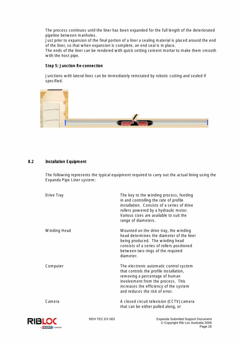
The process continues until the liner has been expanded for the full length of the deteriorated pipeline between manholes. Just prior to expansion of the final portion of a liner a sealing material is placed around the end of the liner, so that when expansion is complete, an end seal is in place. The ends of the liner can be rendered with quick setting cement mortar to make them smooth with the host pipe. Step 5: Junction ReStep 5: Junction ReStep 5: Junction ReStep 5: Junction Re----connectionconnectionconnectionconnection Junctions with lateral lines can be immediately reinstated by robotic cutting and sealed if specified.
8.28.28.28.2 Installation EquipmentInstallation EquipmentInstallation EquipmentInstallation Equipment
The following represents the typical equipment required to carry out the actual lining using the Expanda Pipe Liner system: Drive Tray The key to the winding process, feeding
in and controlling the rate of profile installation. Consists of a series of drive rollers powered by a hydraulic motor. Various sizes are available to suit the range of diameters.
Winding Head Mounted on the drive tray, the winding head determines the diameter of the liner being produced. The winding head consists of a series of rollers positioned between two rings of the required diameter.
Computer The electronic automatic control system that controls the profile installation, removing a percentage of human involvement from the process. This increases the efficiency of the system and reduces the risk of error.
Camera A closed circuit television (CCTV) camera that can be either pulled along, or
REH TEC EX 003 Expanda Submittal Support Document © Copyright Rib Loc Australia 2006
Page 27
mounted on a remote controlled tractor. Used in surveying the pipe and monitoring the progress of Expanda Pipe installation.
Ancillary Equipment Profile Spool and Holder Wire Puller Glue System Remote Cutter (for the reinstatement of lateral service connections – if applicable) Truck (for transport, control centre, crane facility, etc.) Packers (for grouting – if applicable) Plugs (for testing and flow control)
Safety Equipment As required by local regulations. In addition the following would normally be required: o Truck with crane o Generator o Compressor o Rib Loc specialist winding equipment o Ventilation Equipment
Typically a minimal footprint is required with no more than 50 square metres needed. Equipment can be positioned within one lane of traffic and brought right up to the manhole of the line to be rehabilitated.
8.38.38.38.3 BendsBendsBendsBends
The Expanda Pipe system can accommodate long radius bends. Sharp radius bends must be evaluated on a case by case basis.
8.48.48.48.4 TestingTestingTestingTesting
Testing should be carried out in accordance with acceptable practice or as per the requirements of the customer.
REH TEC EX 003 Expanda Submittal Support Document © Copyright Rib Loc Australia 2006
Page 28
9999 EEEExpanda Pipe xpanda Pipe xpanda Pipe xpanda Pipe Approvals and ReferencesApprovals and ReferencesApprovals and ReferencesApprovals and References
9.19.19.19.1 AAAAustraliaustraliaustraliaustralia
Expanda Pipe has been widely approved for use in Australia in the major capital cities including Sydney, Melbourne, Adelaide and Canberra. Several councils and regional cities have also approved the technology for use in their system.
9.29.29.29.2 InternationalInternationalInternationalInternational
Expanda Pipe has been used in several countries outside of Australia including New Zealand, United States of America, Hong Kong, China, Taiwan, United Arab Emirates, Saudi Arabia, France and Germany.
REH TEC EX 003 Expanda Submittal Support Document © Copyright Rib Loc Australia 2006
Page 29
10101010 Rib Loc Quality SystemRib Loc Quality SystemRib Loc Quality SystemRib Loc Quality System
Rib Loc Australia is a quality endorsed company with AS/NZS ISO 9001–2000 certification. The quality system incorporates systems, procedures, work instructions and forms addressing all functional areas and activities. For the production of Expanda Pipe profile Rib Loc has systems, procedures and work instructions for quality control of: o Raw materials o Mixing of PVC dry blend for extrusion o Extrusion of profile o Testing of profile o Packing and transport of profile
REH TEC EX 003 Expanda Submittal Support Document © Copyright Rib Loc Australia 2006
Page 30
11111111 Environmental ImpactEnvironmental ImpactEnvironmental ImpactEnvironmental Impact
The fact that Expanda Pipe is a mechanical process gives the system an environmental advantage over competitive systems. No chemical processes are used on site therefore there is no risk of chemical spills and no requirement for the safe disposal of contaminated process water. Also, there is no heat or steam used on site meaning excess heat does not escape to the environment. The Expanda Pipe process is also extremely quiet as the process is taking place underground. The only noise produced is from the generator used to supply the hydraulic power pack driving the winding machine. This noise can be reduced through the use of sound proofing and is typically used. Other forms of noise production are eliminated using the Expanda Pipe system. The elimination of large pumps required for overpumping and the minimal number of vehicles on site ensure noise is kept to a minimum. The very low noise level makes the Rotaloc system ideal for residential areas. The removal of overpumping makes the system even more suitable for residential areas as there is no restriction to access as occurs when the required above ground pipe work is present. In recent years, as environmental impact has become a greater concern, damaged or leaking pipelines in sensitive areas have drawn greater attention. Government bodies are heavily penalising those causing damage, or potential damage, to the environment. The small number of support vehicles required and the ability of the system to work remotely from these vehicles means that the system can be used in extremely sensitive areas. Another environmental advantage is the ability of the system to operate without the need for excavation. The winding machine can be disassembled to fit through existing access chamber openings. The site can be secured at the end of each working day simply by replacing access chamber covers. The development of Expanda Pipe, a cost-effective system of rehabilitation will allow water authorities to make earlier and more widespread use of pipeline rehabilitation, thereby avoiding environmental problems associated with the breakdown of decayed pipes leading to pollution of surrounding soils.