Embed Size (px)
Citation preview
GAS TURBINE OPERATION AND MAINTENANCEP2M FTUISeptember 2008
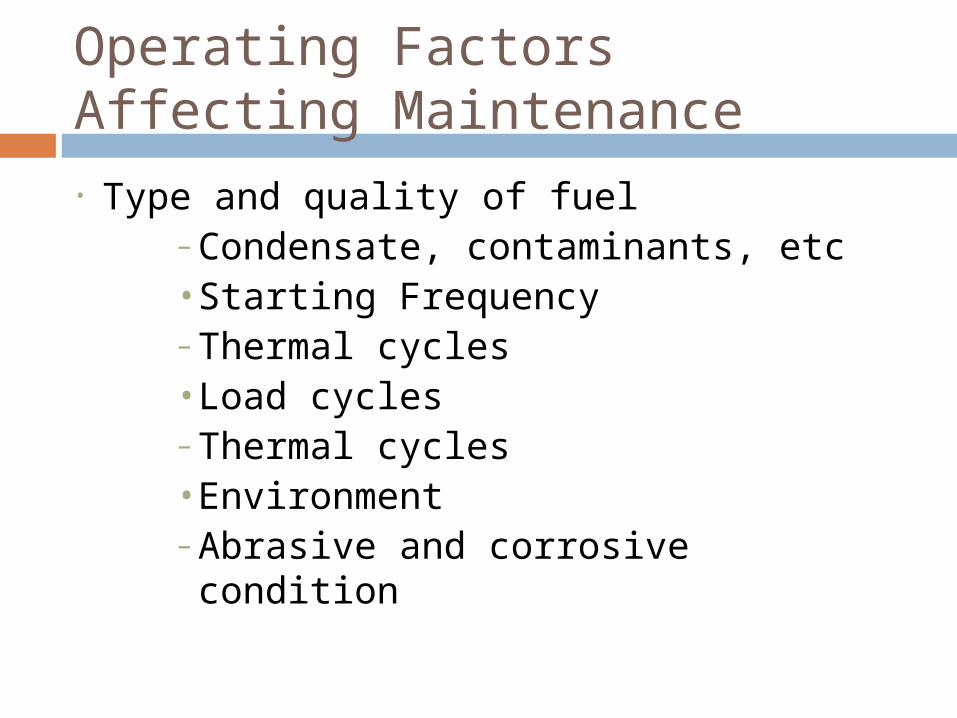
Operating Factors Affecting Maintenance• Type and quality of fuel
– Condensate, contaminants, etc• Starting Frequency– Thermal cycles• Load cycles– Thermal cycles• Environment– Abrasive and corrosive condition
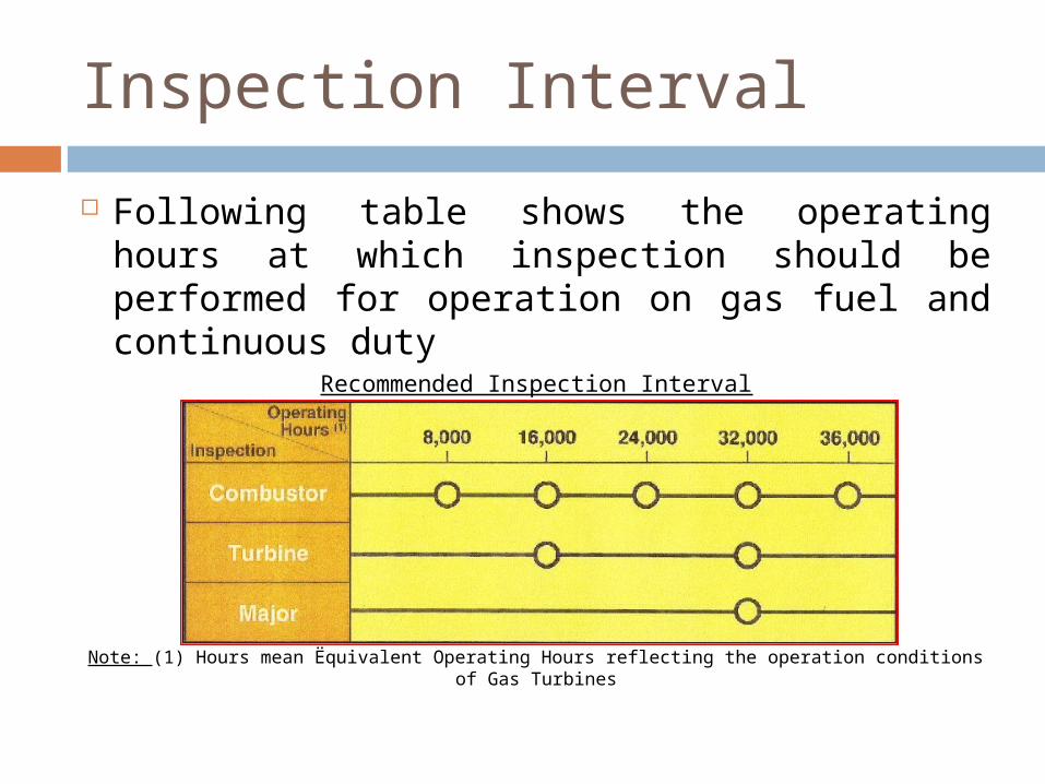
Inspection Interval Following table shows the operating hours at
which inspection should be performed for operation on gas fuel and continuous duty
Recommended Inspection Interval
Note: (1) Hours mean Ëquivalent Operating Hours”reflecting the operation conditions of Gas Turbines
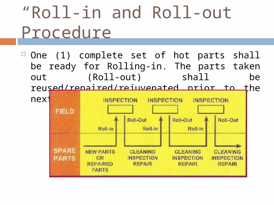
“Roll-in and Roll-out” Procedure
One (1) complete set of hot parts shall be ready for Rolling-in. The parts taken out (Roll-out) shall be reused/repaired/rejuvenated prior to the next inspection
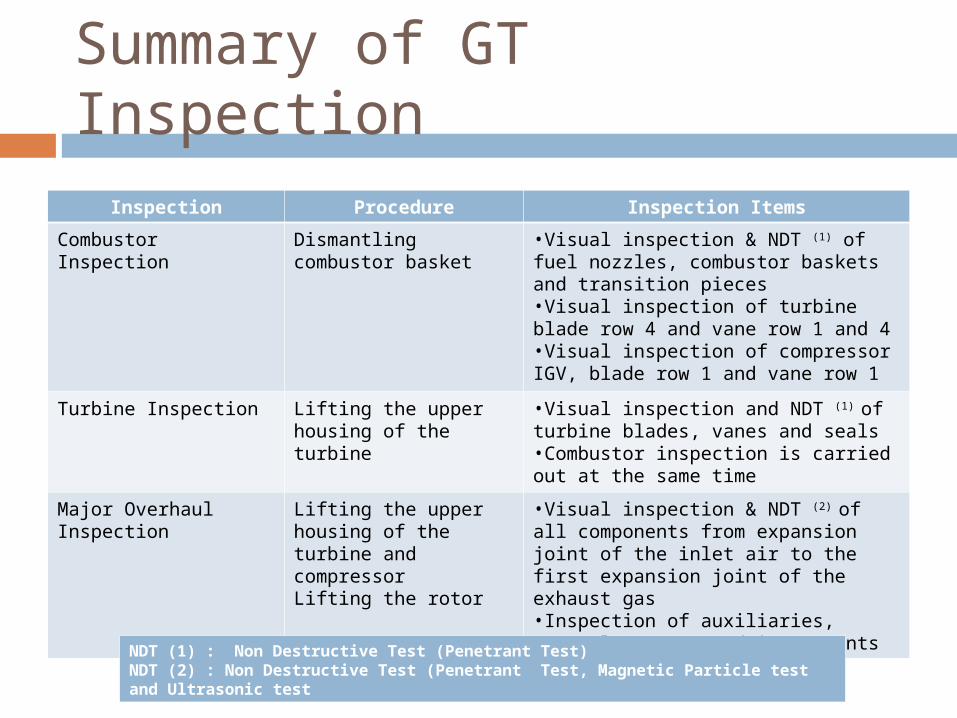
Summary of GT Inspection
Inspection Procedure Inspection ItemsCombustor Inspection Dismantling combustor
basket•Visual inspection & NDT (1) of fuel nozzles, combustor baskets and transition pieces•Visual inspection of turbine blade row 4 and vane row 1 and 4•Visual inspection of compressor IGV, blade row 1 and vane row 1
Turbine Inspection Lifting the upper housing of the turbine
•Visual inspection and NDT (1) of turbine blades, vanes and seals•Combustor inspection is carried out at the same time
Major Overhaul Inspection
Lifting the upper housing of the turbine and compressorLifting the rotor
•Visual inspection & NDT (2) of all components from expansion joint of the inlet air to the first expansion joint of the exhaust gas•Inspection of auxiliaries, control systems and instruments
NDT (1) : Non Destructive Test (Penetrant Test)NDT (2) : Non Destructive Test (Penetrant Test, Magnetic Particle test and Ultrasonic test
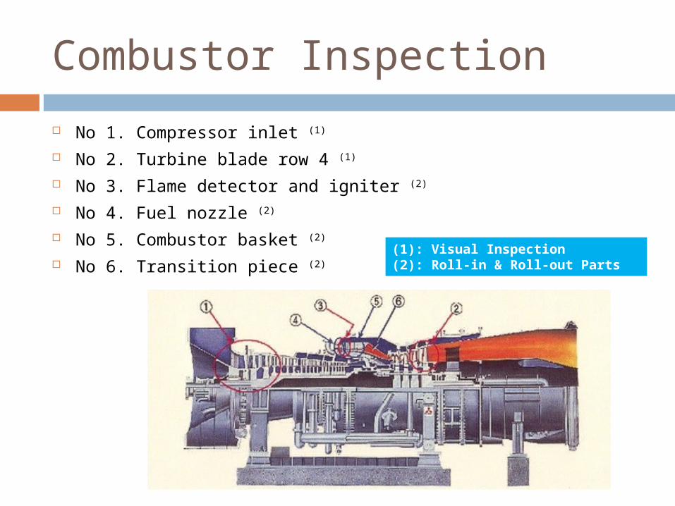
Combustor Inspection No 1. Compressor inlet (1)
No 2. Turbine blade row 4 (1)
No 3. Flame detector and igniter (2)
No 4. Fuel nozzle (2)
No 5. Combustor basket (2)
No 6. Transition piece (2)(1): Visual Inspection(2): Roll-in & Roll-out Parts
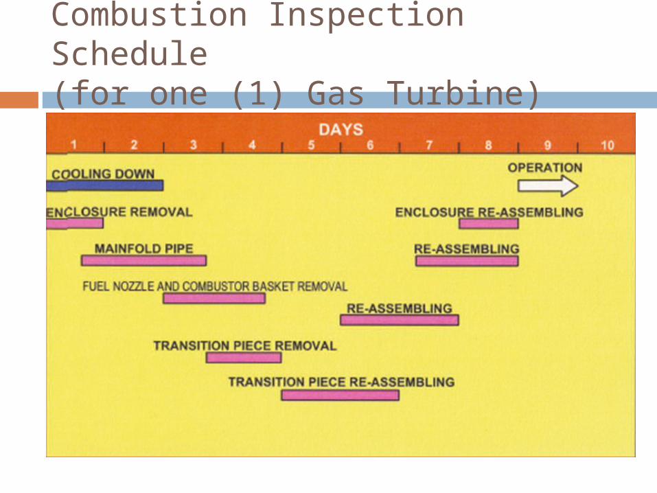
Combustion Inspection Schedule(for one (1) Gas Turbine)
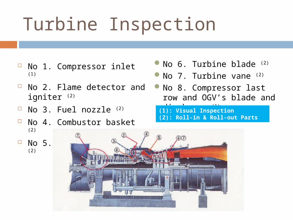
Turbine Inspection
No 1. Compressor inlet (1)
No 2. Flame detector and igniter (2)
No 3. Fuel nozzle (2)
No 4. Combustor basket (2)
No 5. Transition piece (2)
No 6. Turbine blade (2)
No 7. Turbine vane (2)
No 8. Compressor last row and OGV’s blade and diaphragm (1)
(1): Visual Inspection(2): Roll-in & Roll-out Parts
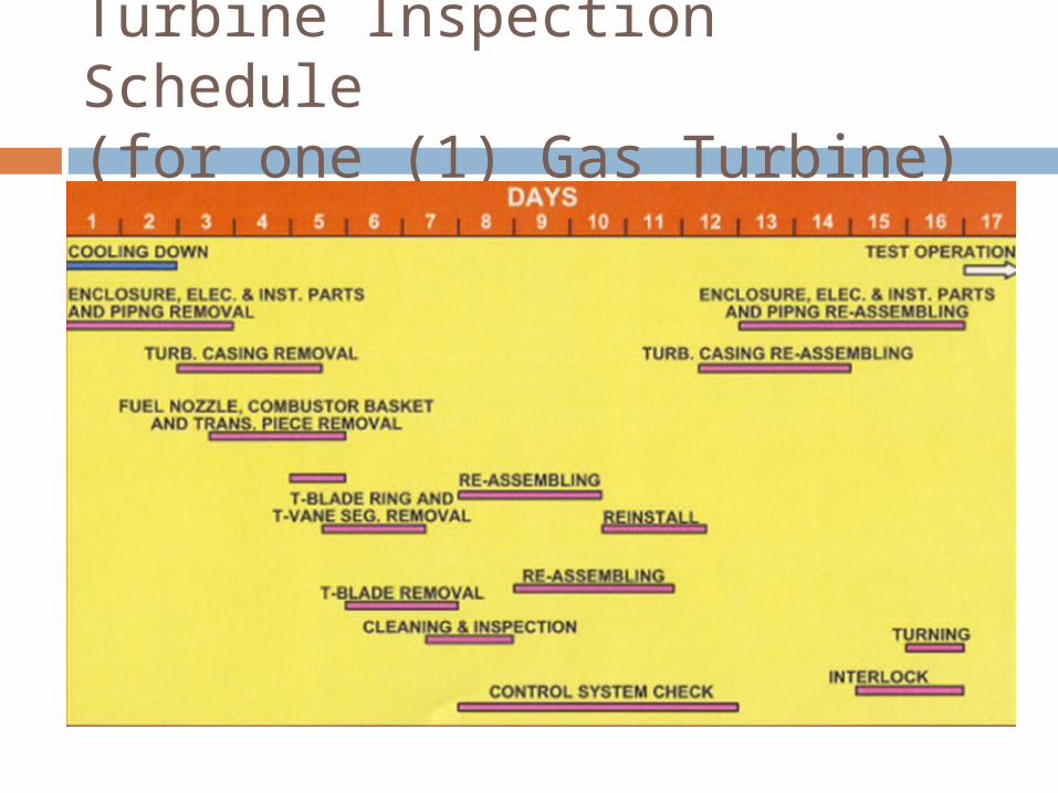
Turbine Inspection Schedule(for one (1) Gas Turbine)
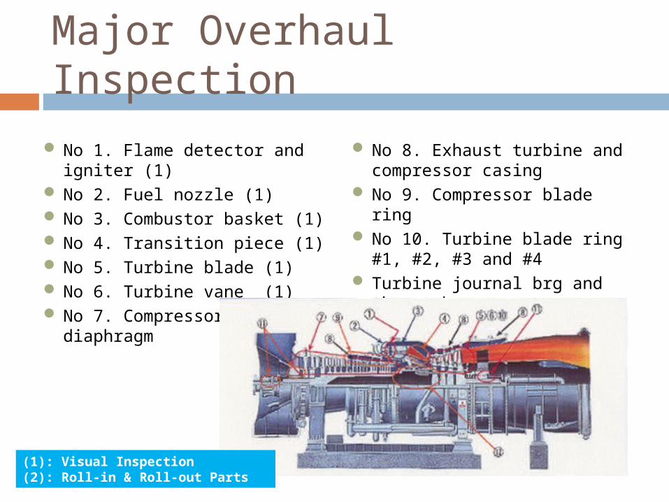
Major Overhaul Inspection
No 1. Flame detector and igniter (1)
No 2. Fuel nozzle (1) No 3. Combustor basket (1) No 4. Transition piece (1) No 5. Turbine blade (1) No 6. Turbine vane (1) No 7. Compressor blade and
diaphragm
No 8. Exhaust turbine and compressor casing
No 9. Compressor blade ring No 10. Turbine blade ring #1,
#2, #3 and #4 Turbine journal brg and thrust
brg Rotor (2)
(1): Visual Inspection(2): Roll-in & Roll-out Parts
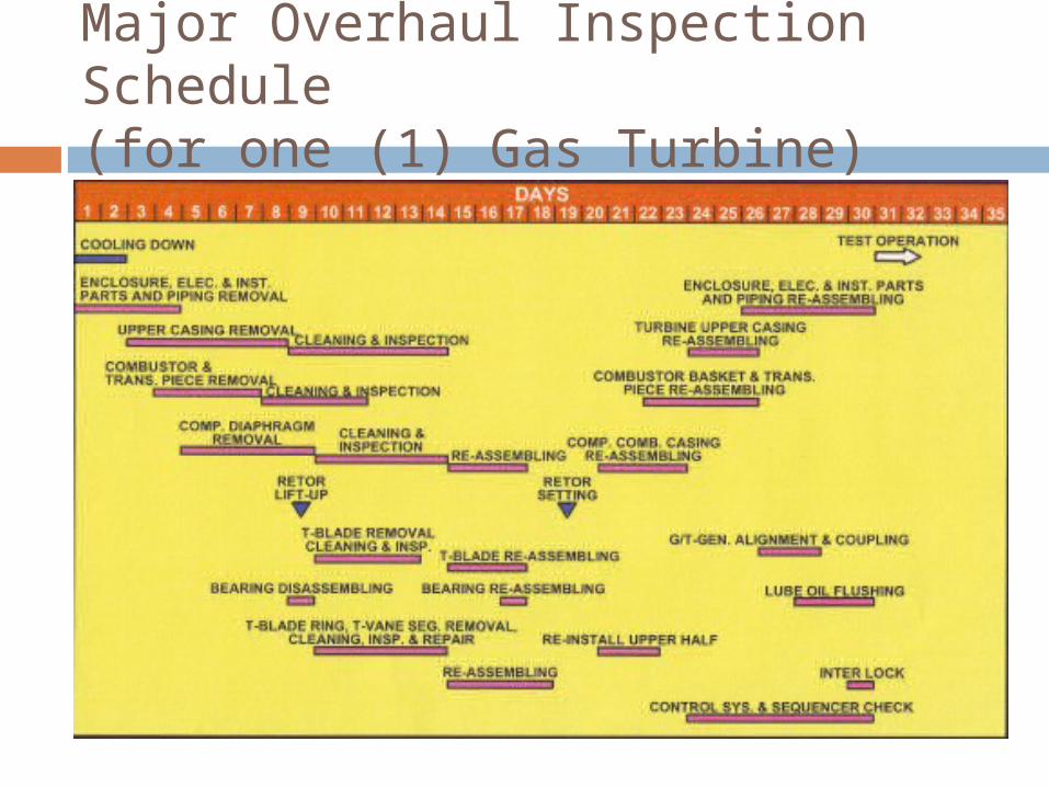
Major Overhaul Inspection Schedule(for one (1) Gas Turbine)
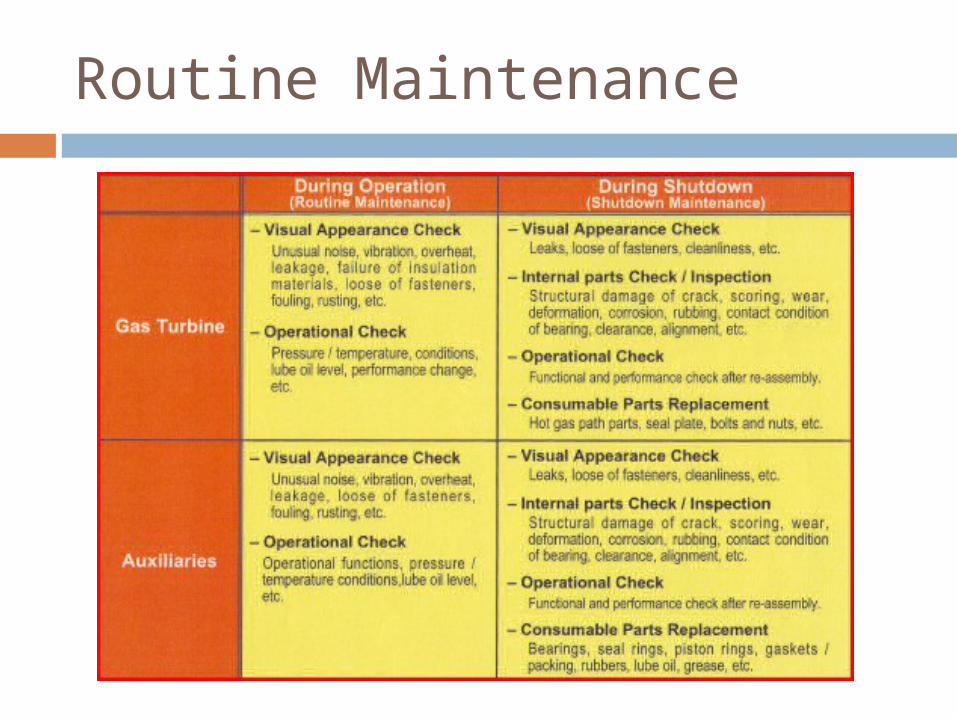
Routine Maintenance
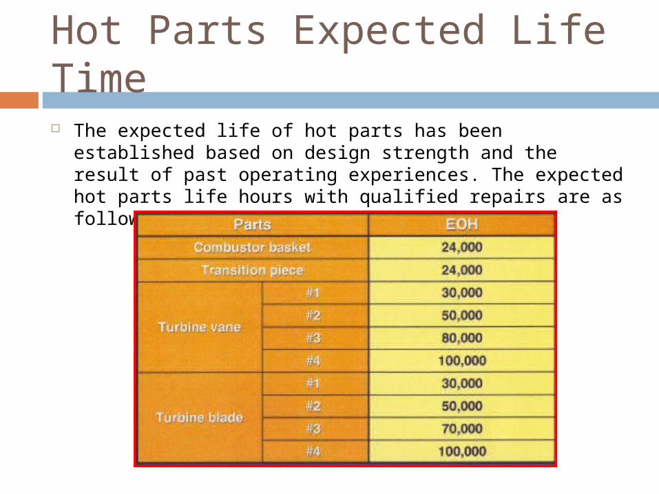
Hot Parts Expected Life Time The expected life of hot parts has been established based on
design strength and the result of past operating experiences. The expected hot parts life hours with qualified repairs are as follows:
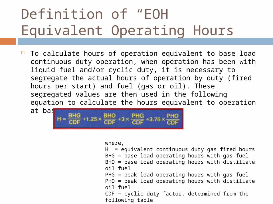
Definition of “EOH”Equivalent Operating Hours To calculate hours of operation equivalent to base load continuous duty
operation, when operation has been with liquid fuel and/or cyclic duty, it is necessary to segregate the actual hours of operation by duty (fired hours per start) and fuel (gas or oil). These segregated values are then used in the following equation to calculate the hours equivalent to operation at base load with gas fuel.
where,H = equivalent continuous duty gas fired hoursBHG = base load operating hours with gas fuel BHO = base load operating hours with distillate oil fuelPHG = peak load operating hours with gas fuel PHO = peak load operating hours with distillate oil fuelCDF = cyclic duty factor, determined from the following table
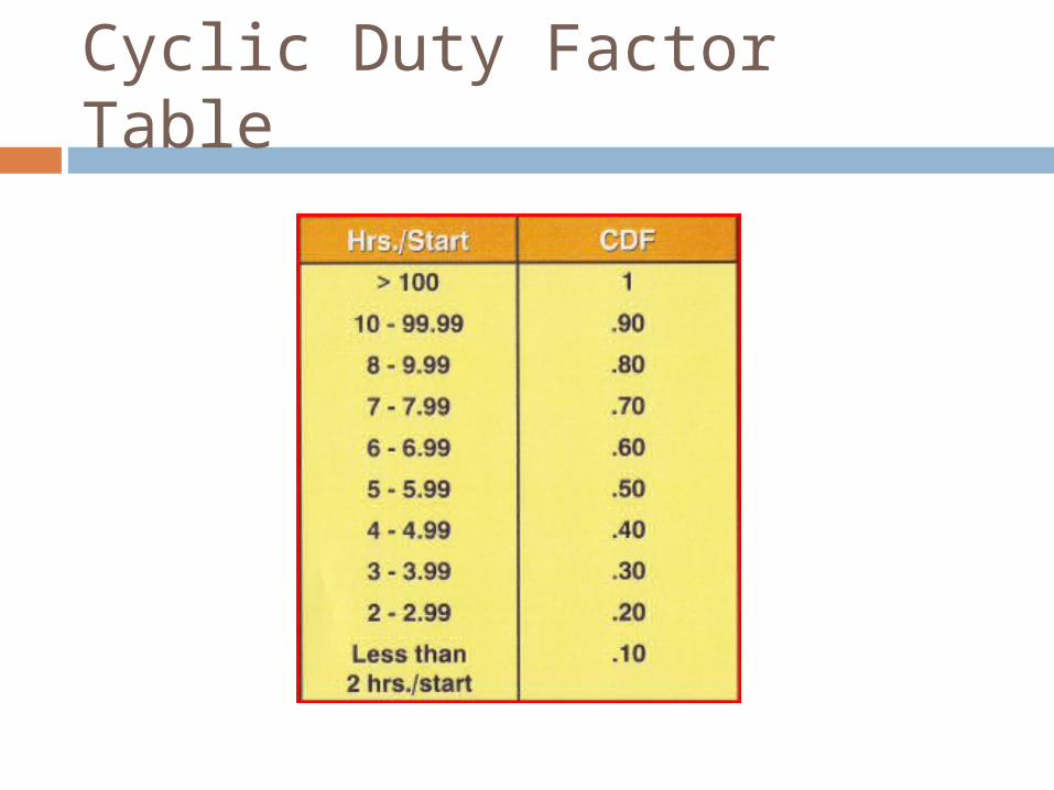
Cyclic Duty Factor Table
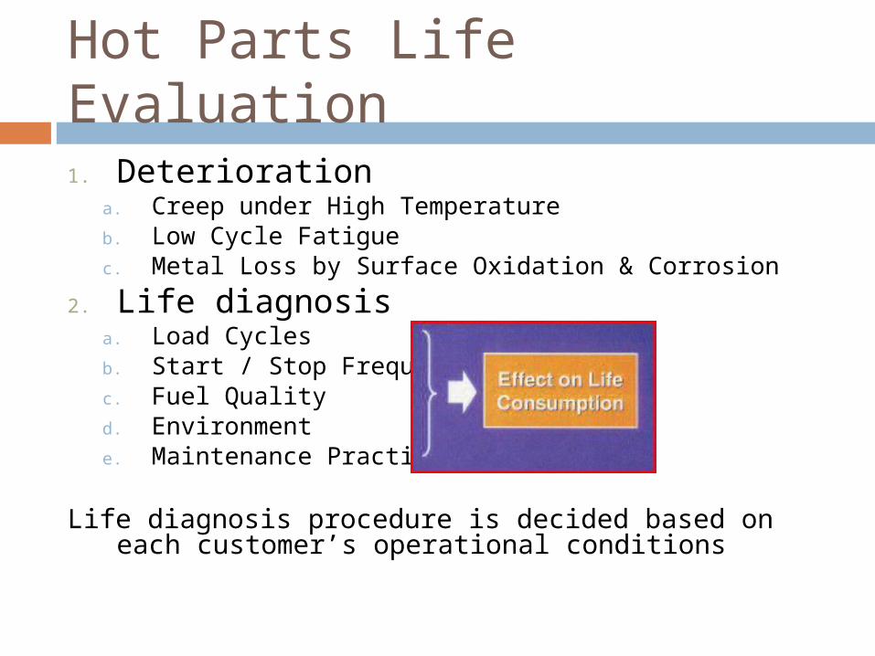
Hot Parts Life Evaluation1. Deterioration
a. Creep under High Temperatureb. Low Cycle Fatiguec. Metal Loss by Surface Oxidation & Corrosion
2. Life diagnosisa. Load Cyclesb. Start / Stop Frequencyc. Fuel Qualityd. Environmente. Maintenance Practice
Life diagnosis procedure is decided based on each customer’s operational conditions
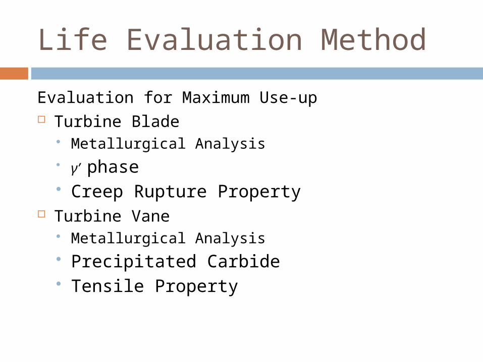
Life Evaluation Method
Evaluation for Maximum Use-up Turbine Blade
Metallurgical Analysis γ’ phase Creep Rupture Property
Turbine Vane Metallurgical Analysis Precipitated Carbide Tensile Property
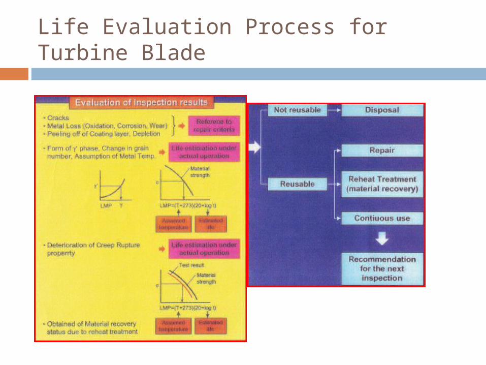
Life Evaluation Process for Turbine Blade
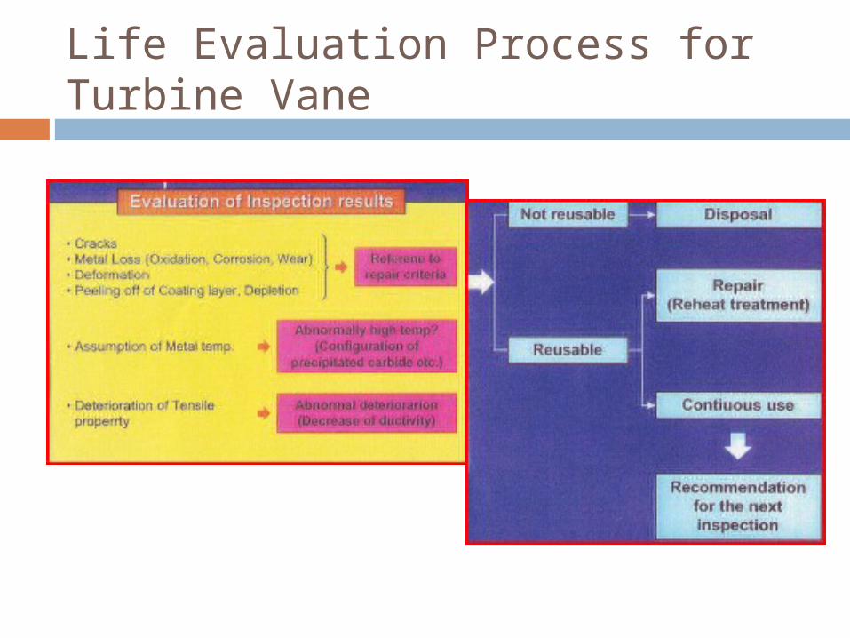
Life Evaluation Process for Turbine Vane
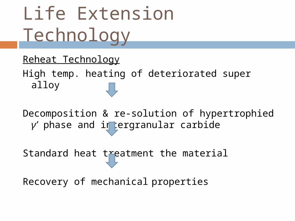
Life Extension Technology
Reheat TechnologyHigh temp. heating of deteriorated super alloy
Decomposition & re-solution of hypertrophied γ’ phase and intergranular carbide
Standard heat treatment the material
Recovery of mechanical properties

Terima Kasih


![31A - Gas Turbine Fundamentals[1]](https://img.pdfslide.us/doc/110x75/5524f5f94a7959c2488b49f0/31a-gas-turbine-fundamentals1.jpg)