Embed Size (px)
Citation preview
Houston Chapter Meeting
September 11, 2013John Cummins
Hydrotex
VP Product Technology
Wind Turbine Lubrication
Comparison of Power Sources
• Huge single footprint asset
• Redundant equipment with easy access
• Multiple sensors and performance monitors
• On-site Manned Control Room
• On-site Maintenance Crew
• Small footprint assets scattered over a wide, isolated area
• No redundancy equipment in nacelle: 80m + above ground
• Few if any sensors or monitors
• No centralized monitoring
• Off-site Maintenance Crew
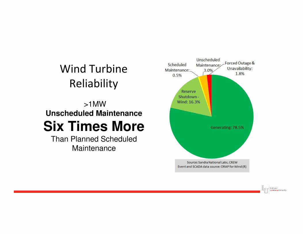
Wind Turbine
Reliability
>1MWUnscheduled Maintenance
Six Times MoreThan Planned Scheduled
Maintenance
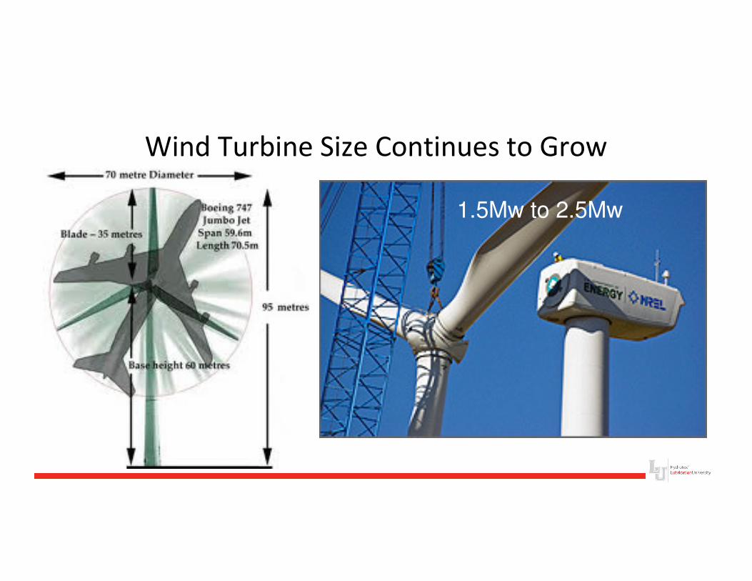
Wind Turbine Size Continues to Grow
1.5Mw to 2.5Mw
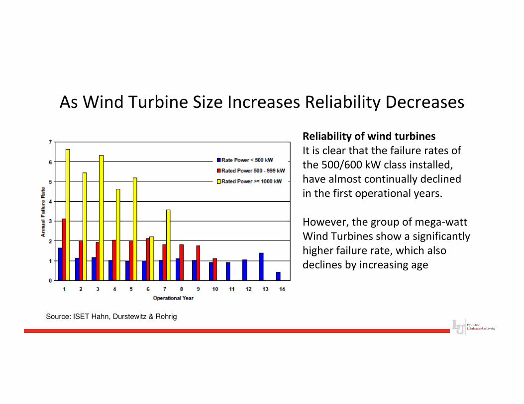
As Wind Turbine Size Increases Reliability Decreases
Reliability of wind turbines
It is clear that the failure rates of
the 500/600 kW class installed,
have almost continually declined
in the first operational years.
However, the group of mega-watt
Wind Turbines show a significantly
higher failure rate, which also
declines by increasing age
Source: ISET Hahn, Durstewitz & Rohrig
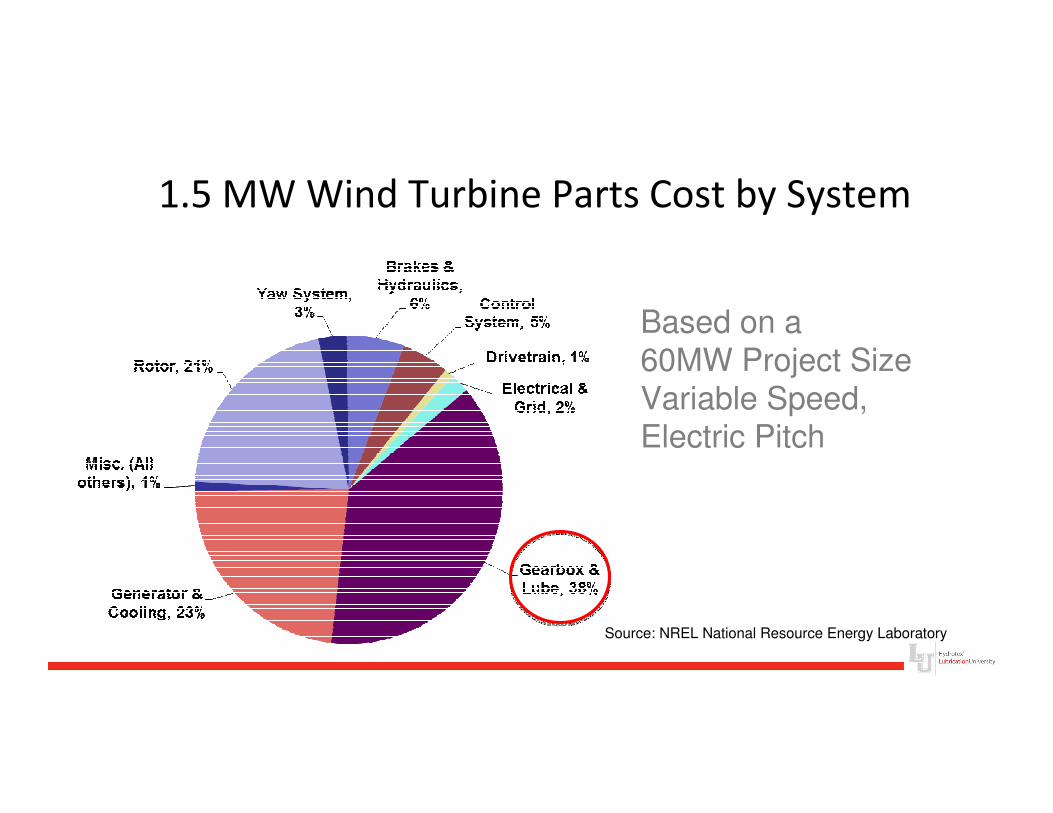
Based on a 60MW Project Size
Variable Speed,Electric Pitch
Source: NREL National Resource Energy Laboratory
1.5 MW Wind Turbine Parts Cost by System
Gear Box
Lubrication Fundamentals
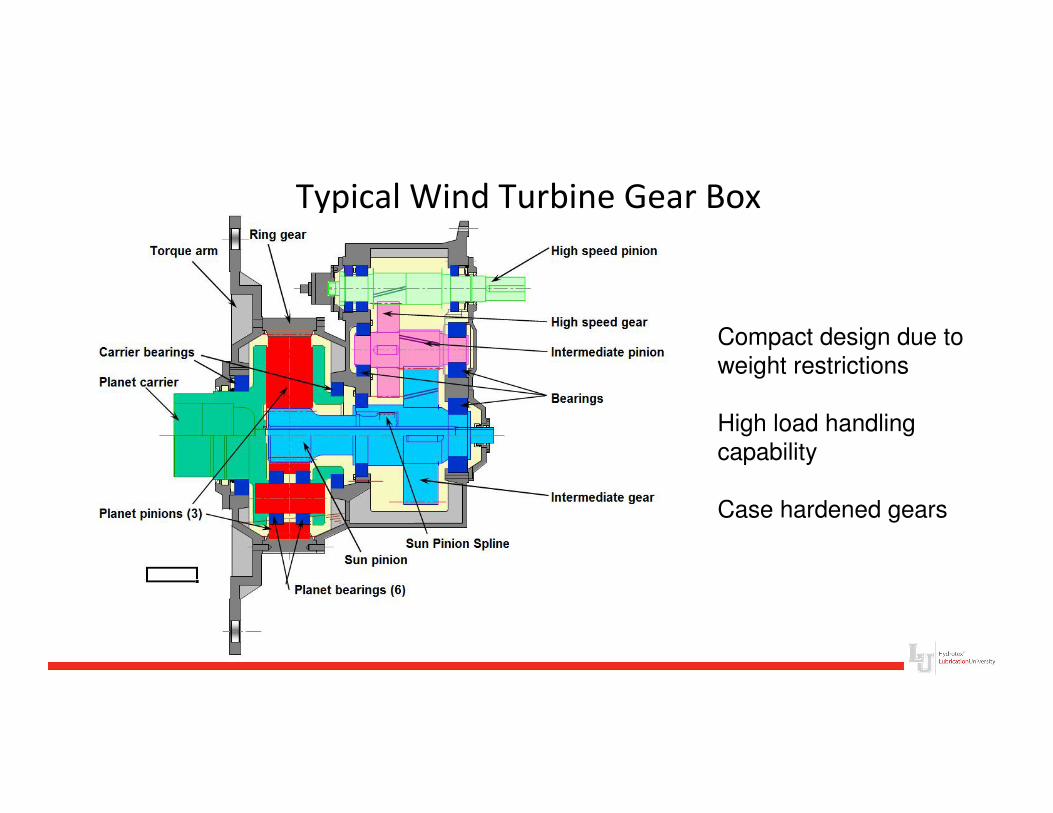
Typical Wind Turbine Gear Box
Compact design due to
weight restrictions
High load handling
capability
Case hardened gears

Understanding Stress Loads
in the Gear Box
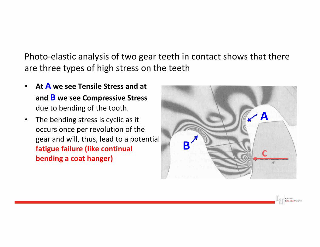
Photo-elastic analysis of two gear teeth in contact shows that there
are three types of high stress on the teeth
• At A we see Tensile Stress and at
and B we see Compressive Stress
due to bending of the tooth.
• The bending stress is cyclic as it
occurs once per revolution of the
gear and will, thus, lead to a potential
fatigue failure (like continual
bending a coat hanger)
A
BC
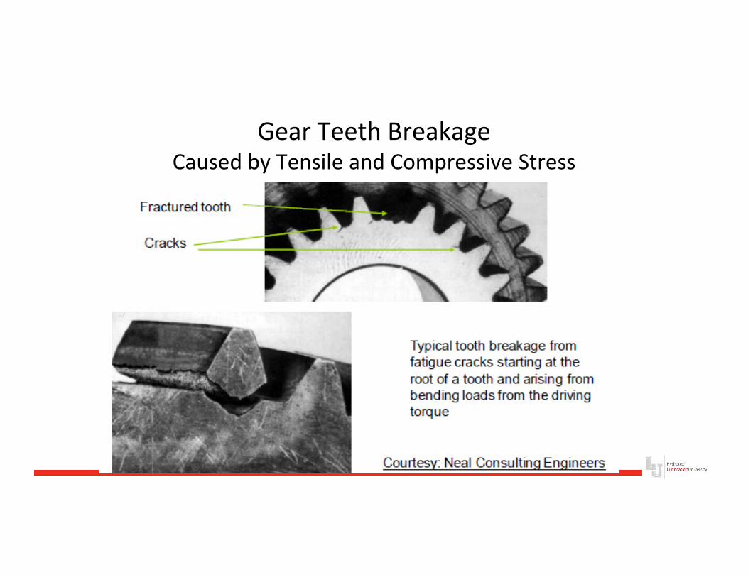
Gear Teeth BreakageCaused by Tensile and Compressive Stress
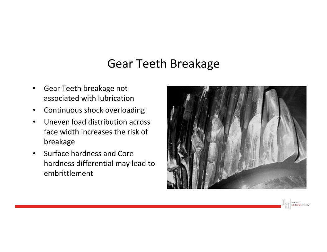
Gear Teeth Breakage
• Gear Teeth breakage not
associated with lubrication
• Continuous shock overloading
• Uneven load distribution across
face width increases the risk of
breakage
• Surface hardness and Core
hardness differential may lead to
embrittlement
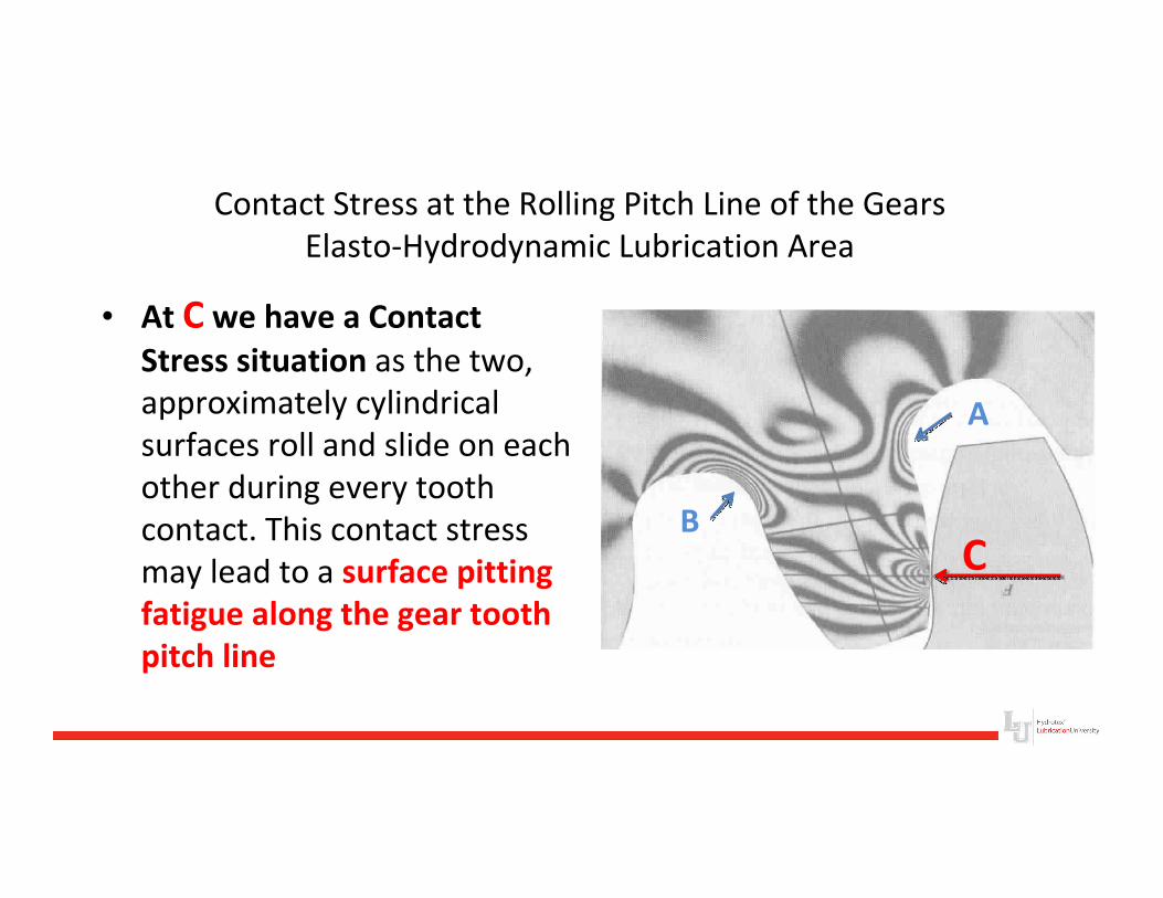
Contact Stress at the Rolling Pitch Line of the Gears
Elasto-Hydrodynamic Lubrication Area
• At C we have a Contact
Stress situation as the two,
approximately cylindrical
surfaces roll and slide on each
other during every tooth
contact. This contact stress
may lead to a surface pitting
fatigue along the gear tooth
pitch line
A
BC
Pitting - Hertzian Fatigue
• Pitting occurs when a fatigue crack initiates either at the surface
of a gear tooth or a small depth below the surface
• Small particles are removed from the surface of the tooth
because of the high contact forces
• Pitting is actually the metal fatigue failure of the tooth surface
• Surface irregularities caused by pitting lead to loss of oil film in
the contact zone and eventual failure
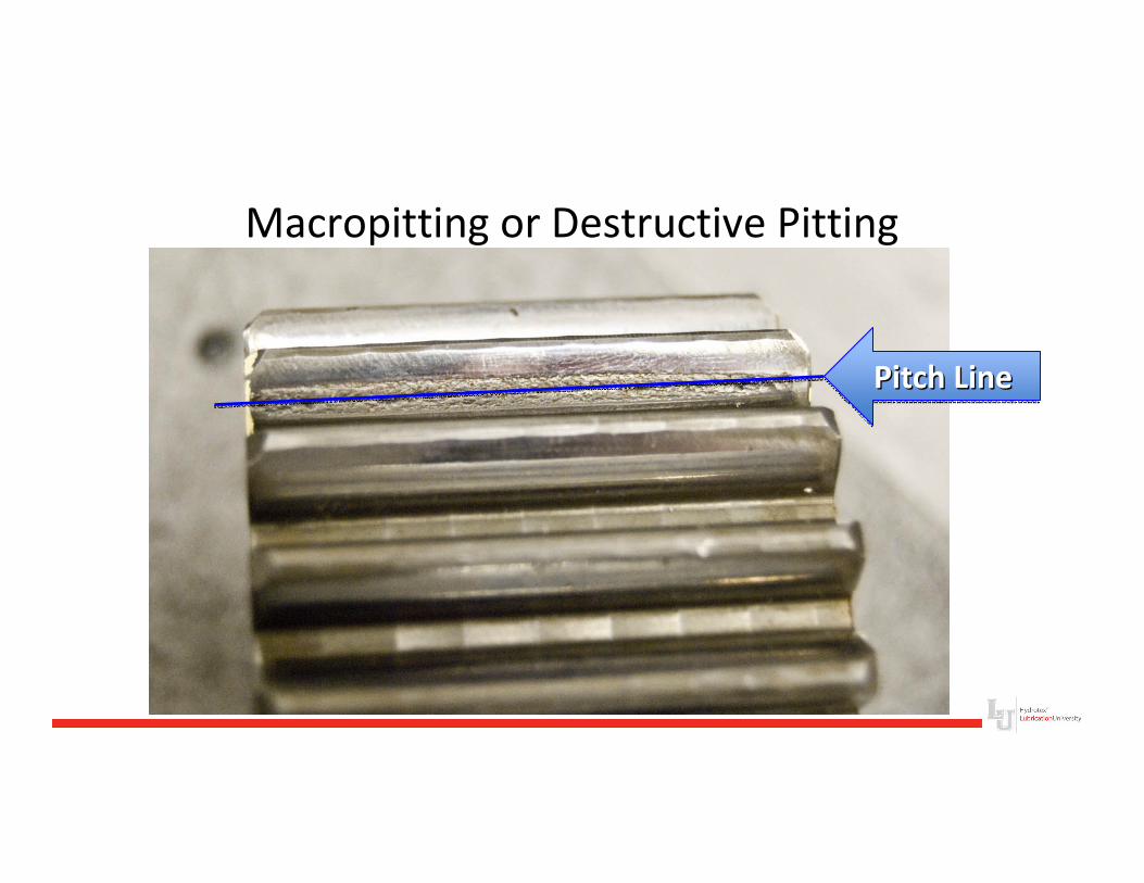
Macropitting or Destructive Pitting
Pitch LinePitch LinePitch Line
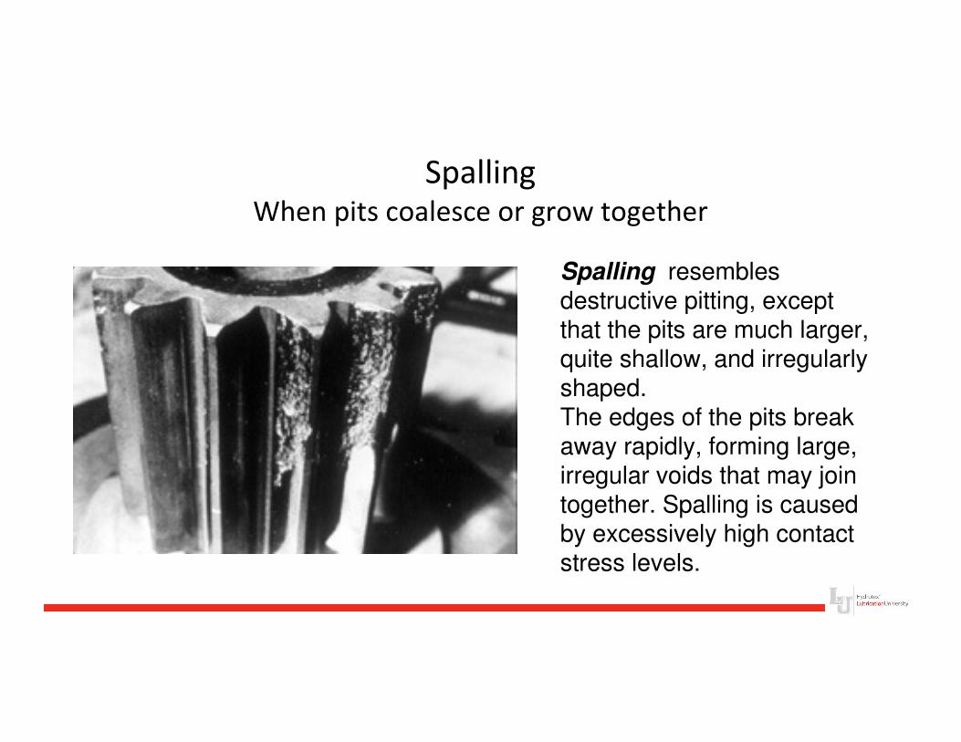
SpallingWhen pits coalesce or grow together
Spalling resembles destructive pitting, except that the pits are much larger, quite shallow, and irregularly shaped. The edges of the pits break away rapidly, forming large, irregular voids that may join together. Spalling is caused by excessively high contact stress levels.
Gear Spalling
Spalling is a term used to describe when a large area of
the gear tooth breaks away, caused by:
• High contact stresses associated with proud areas of the
tooth surface and loss of oil film caused by destructive
pitting
• Excessive or internal stresses (Over Loading)
• Improper heat treatment in surface-hardened gears
The Lubrication Challenge of Micropitting
Lubrication’s Role in Wind Turbine
Reliability and Life
Micropitting
• Micropitting is characterized by the presence of fine surface
pits and the occurrence of local plastic deformation and
shallow surface cracks
• It produces significant wear of the gear surface causing loss
of profile of the teeth leading to noise
• Root Cause Failure analyses show that micropitting is
frequently a primary failure mode responsible for initiating
other secondary failure modes such as macropitting, scuffing,
bending fatigue, and spalling
Micropitting
• Gears subject to extreme loads like those found in Wind
Turbines are surface hardened (carburized, nitrided,
induction hardened and/or flame hardened)
• Micro-pitting, unlike macro-pitting, usually starts away from
the mating pitch line of the gear teeth at the addendum and
dedendum
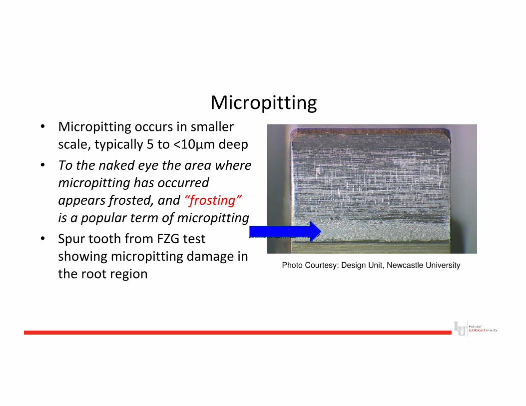
Micropitting• Micropitting occurs in smaller
scale, typically 5 to <10µm deep
• To the naked eye the area where
micropitting has occurred
appears frosted, and “frosting”
is a popular term of micropitting
• Spur tooth from FZG test
showing micropitting damage in
the root regionPhoto Courtesy: Design Unit, Newcastle University
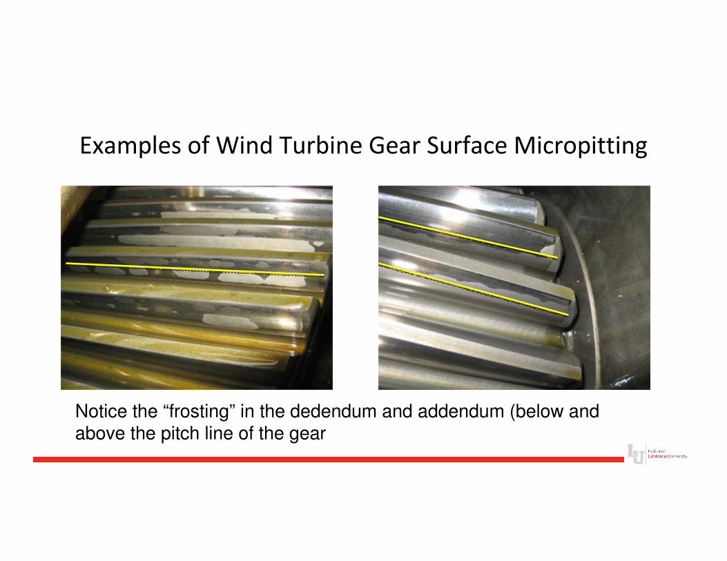
Examples of Wind Turbine Gear Surface Micropitting
Notice the “frosting” in the dedendum and addendum (below and above the pitch line of the gear
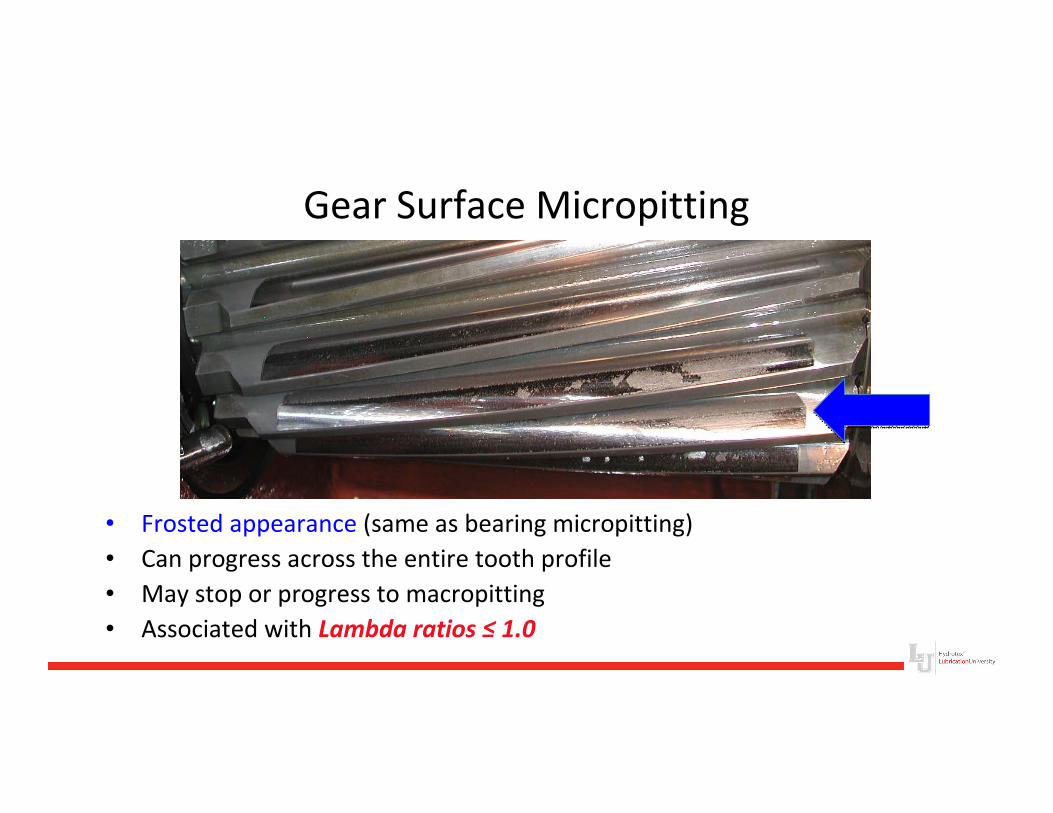
Gear Surface Micropitting
• Frosted appearance (same as bearing micropitting)
• Can progress across the entire tooth profile
• May stop or progress to macropitting
• Associated with Lambda ratios ≤ 1.0
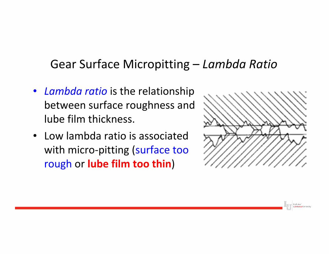
Gear Surface Micropitting – Lambda Ratio
• Lambda ratio is the relationship
between surface roughness and
lube film thickness.
• Low lambda ratio is associated
with micro-pitting (surface too
rough or lube film too thin)
Wind Turbine Gear Boxes Bearings
Are Also Affected by Micropitting
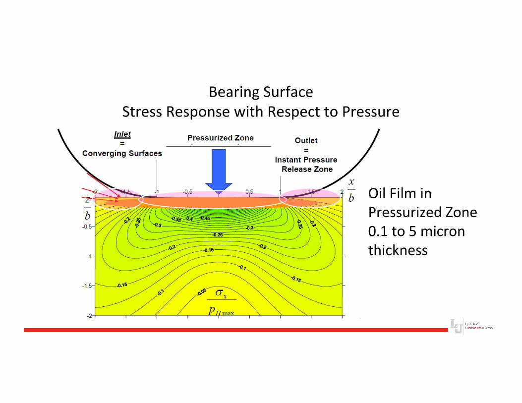
Bearing Surface
Stress Response with Respect to Pressure
Oil Film in
Pressurized Zone
0.1 to 5 micron
thickness
Wind Turbine Bearing Micropitting
• Micropitting is especially detrimental to bearing
function because it alters the geometry of rollers,
raceways, or both
– The altered geometry increases internal clearance
and results in edge stresses that ultimately cause
macropitting and bearing failure
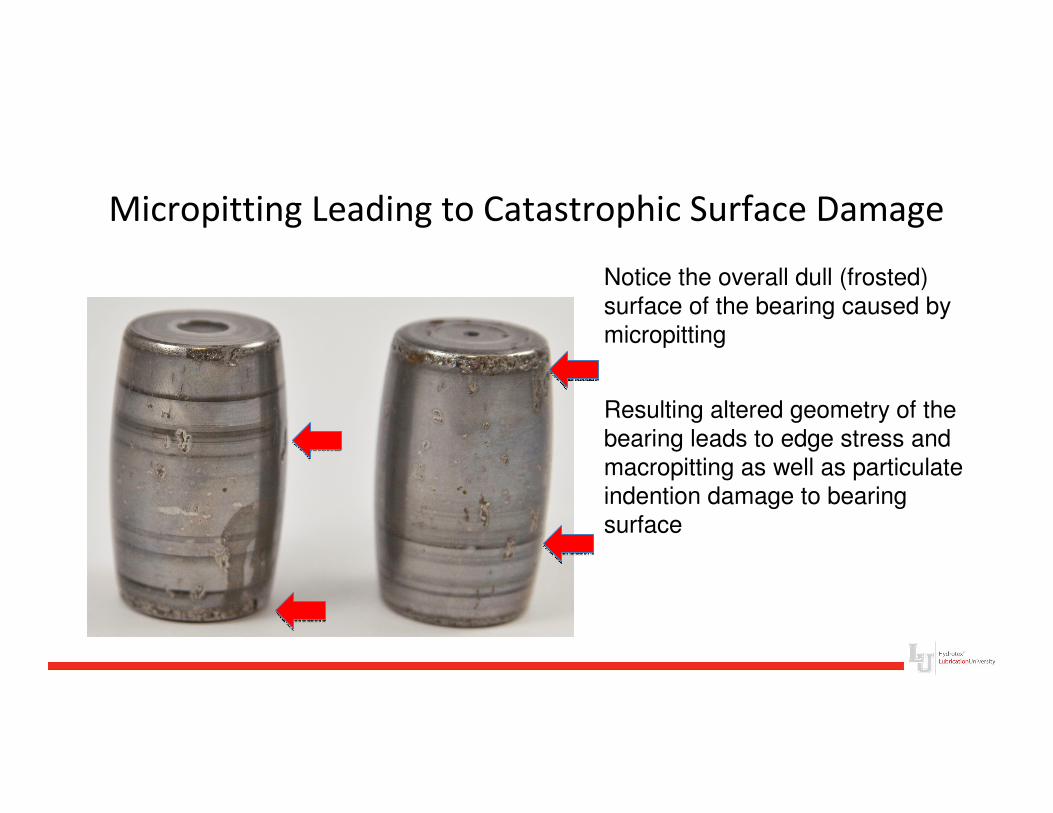
Micropitting Leading to Catastrophic Surface Damage
Notice the overall dull (frosted)
surface of the bearing caused by
micropitting
Resulting altered geometry of the
bearing leads to edge stress and
macropitting as well as particulate
indention damage to bearing
surface
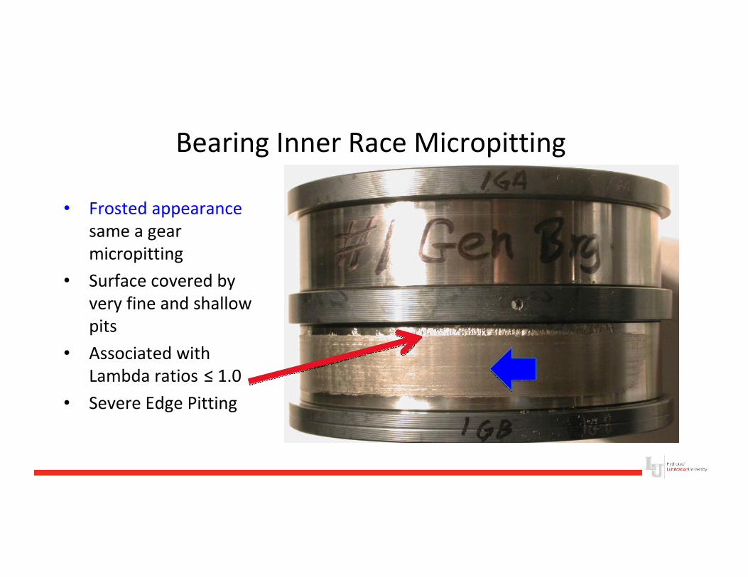
Bearing Inner Race Micropitting
• Frosted appearance
same a gear
micropitting
• Surface covered by
very fine and shallow
pits
• Associated with
Lambda ratios ≤ 1.0
• Severe Edge Pitting
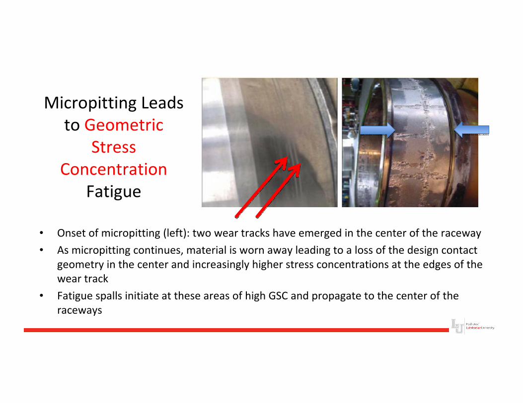
Micropitting Leads
to Geometric
Stress
Concentration
Fatigue
• Onset of micropitting (left): two wear tracks have emerged in the center of the raceway
• As micropitting continues, material is worn away leading to a loss of the design contact
geometry in the center and increasingly higher stress concentrations at the edges of the
wear track
• Fatigue spalls initiate at these areas of high GSC and propagate to the center of the
raceways
Micropitting Increases Surface Roughness• Full film, Elasto-hydrodynamic lubrication depends on
maintaining a oil film of just .01 to 5 microns to separate surface asperities
• 10µm deep Micropitting on both gear surfaces results in a possible combined asperity gap of >20µm – which is greater than the oil film
• RESULT:
– Boundary Lubrication or metal to metal contact
– More loading on the tips of the asperities
– Pitting
– Metal Particle Contamination
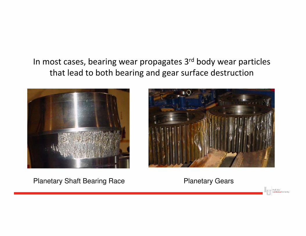
In most cases, bearing wear propagates 3rd body wear particles
that lead to both bearing and gear surface destruction
Planetary Shaft Bearing Race Planetary Gears
If it is Just the Lambda Ratio, Why Not Use Higher
and Higher Viscosity Lubricants Until the
Micropitting Problem is Solved?
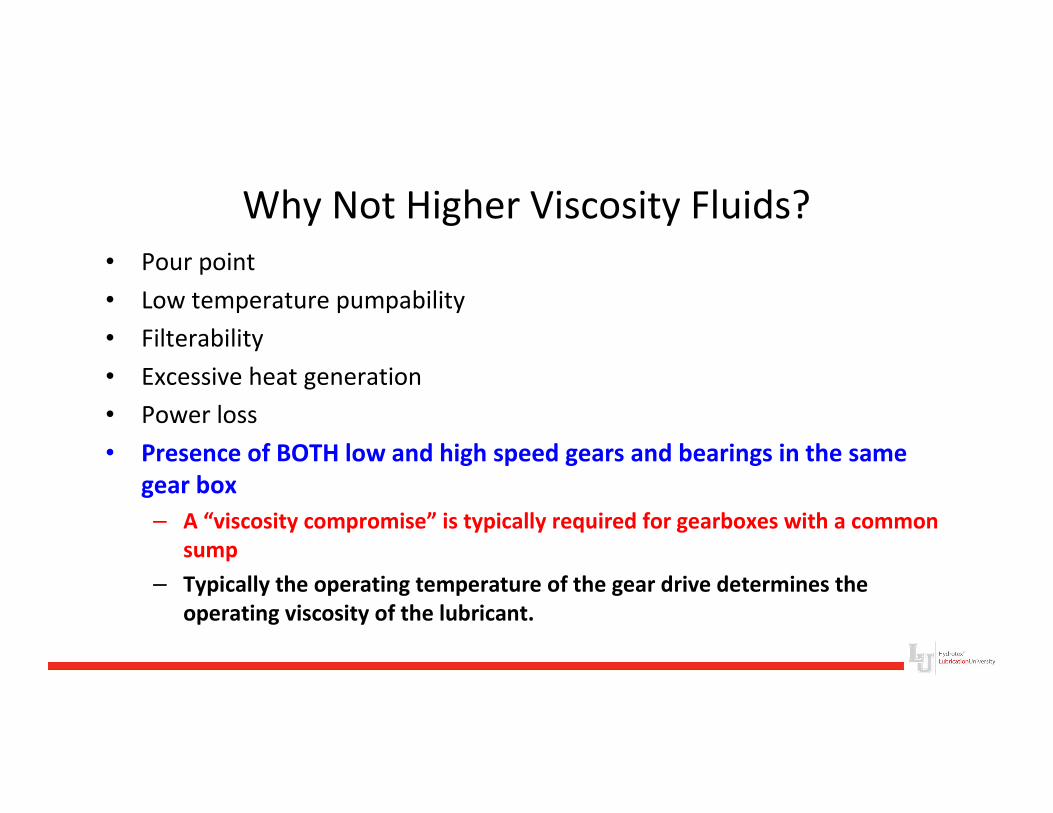
Why Not Higher Viscosity Fluids?
• Pour point
• Low temperature pumpability
• Filterability
• Excessive heat generation
• Power loss
• Presence of BOTH low and high speed gears and bearings in the same
gear box
– A “viscosity compromise” is typically required for gearboxes with a common
sump
– Typically the operating temperature of the gear drive determines the
operating viscosity of the lubricant.
Micropitting Summary
Sliding Friction: Sliding between gear teeth at low lambda in the
addendum and dedendum areas causes tractional forces that
subject asperities to shear stresses which can propagate
micropitting
Contact Compression: Bearing and Raceway contact at low lambda
also subjects asperities to shear stresses which can propagate
micropitting
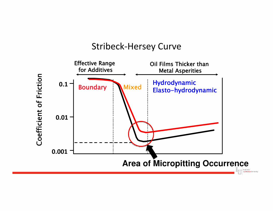
Stribeck-Hersey Curve
0.1
0.01
0.001
Effective Range Effective Range Effective Range Effective Range for Additivesfor Additivesfor Additivesfor Additives
Oil Films Thicker than Oil Films Thicker than Oil Films Thicker than Oil Films Thicker than Metal AsperitiesMetal AsperitiesMetal AsperitiesMetal Asperities
Coefficient of Friction
Coefficient of Friction
Coefficient of Friction
Coefficient of Friction
BoundaryBoundaryBoundaryBoundary MixedMixedMixedMixedHydrodynamicHydrodynamicHydrodynamicHydrodynamicElastoElastoElastoElasto----hydrodynamichydrodynamichydrodynamichydrodynamic
Area of Micropitting Occurrence
Micropitting Prevention
Micropitting Prevention
Control Water Contamination
Many experiments have shown water in oil promotes both micropitting and macropitting
Lubricants are susceptible to water contamination
– Ester-based lubricants
– Mineral oils with EP or anti-wear additives are especially prone to absorbing water
Micropitting & Macropitting Causes
Water Contamination in the gear oil can promote both
micropitting and macropitting through:
– Loss of oil film –
• Water interferes with the pressure-viscosity coefficient of the oil –
it’s ability to momentarily solidify in the contact area
– Corrosive wear (rusting)
– Hydrogen embrittlement
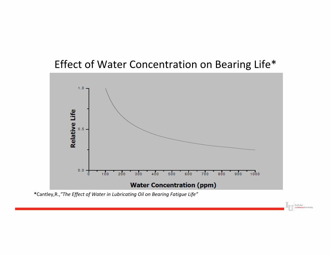
Effect of Water Concentration on Bearing Life*
*Cantley,R.,”The Effect of Water in Lubricating Oil on Bearing Fatigue Life”
Water Contamination of Lubricants
• With water contents of about 200 ppm, a reduction in bearing fatigue life
has been measured, depending on bearing type and composition of the
lubricant
• The primary cause is NOT the viscosity reduction by mixing the oil with
water
• BUT the occasional passage of microscopic water droplets under high
pressure through the lubricating zone and the resulting local lubricating
film breakdown!
• The Number and the Size of the microscopic droplets increase with the
amount of water – which means the Probability of water passing through
the lubricating zone increases as well
Water Contamination of Lubricants
• With water concentrations above 300 ppm, the tendency of oils to form
residues at high temperatures, in the form of
– Sludge
– Varnish
• This not only accelerated the aging of the base oils, it also causes additives
to precipitate out or reduces their effectiveness
• An increased risk of surface CORROSION has to be expected if there is
free water in a lubricating system
Water Contamination - Emulsions
• Thickened Oil/Water Emulsions also suspend abrasive
particles in lubricants and cause surface damage by
indenting and scratching the metal surface, causing
stress concentrations, and disrupting the lubricant film
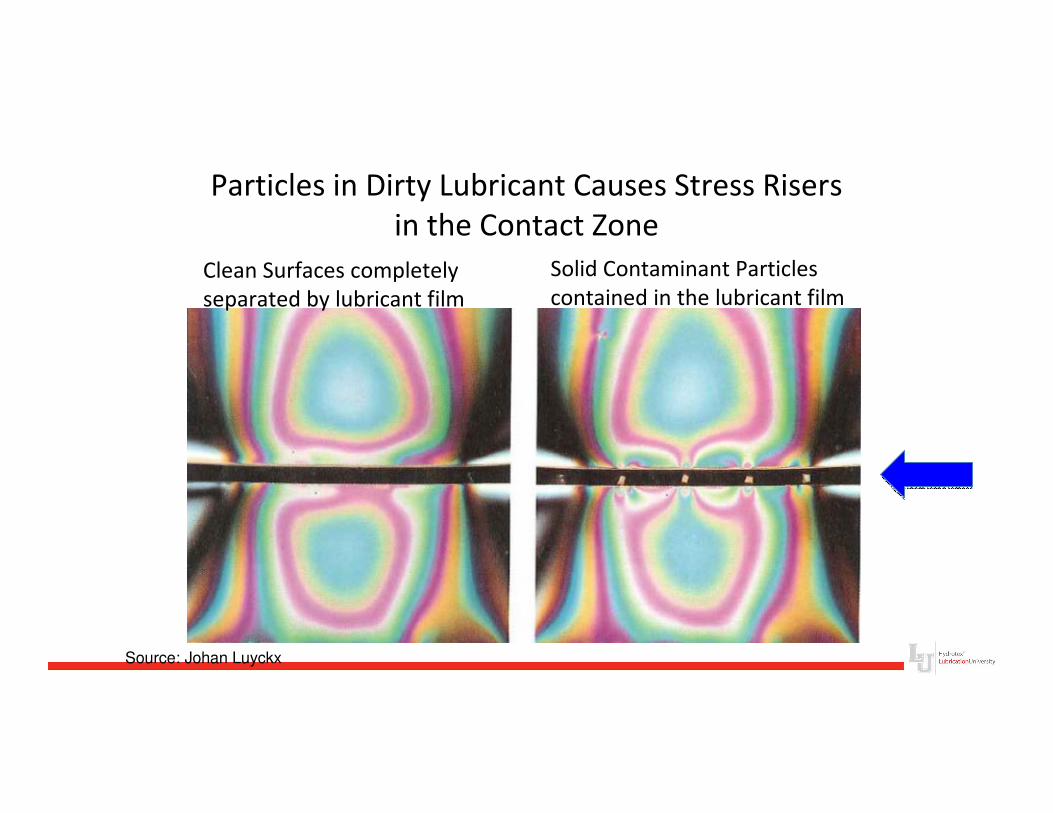
Particles in Dirty Lubricant Causes Stress Risers
in the Contact Zone
Clean Surfaces completely
separated by lubricant film
Solid Contaminant Particles
contained in the lubricant film
Source: Johan Luyckx
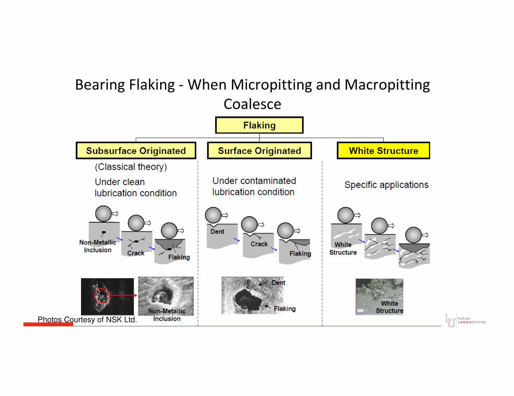
Bearing Flaking - When Micropitting and Macropitting
Coalesce
Photos Courtesy of NSK Ltd.
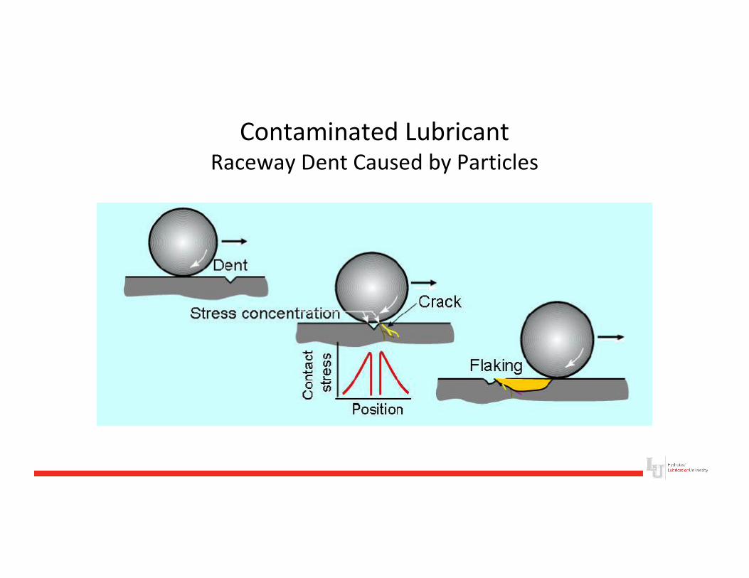
Contaminated LubricantRaceway Dent Caused by Particles
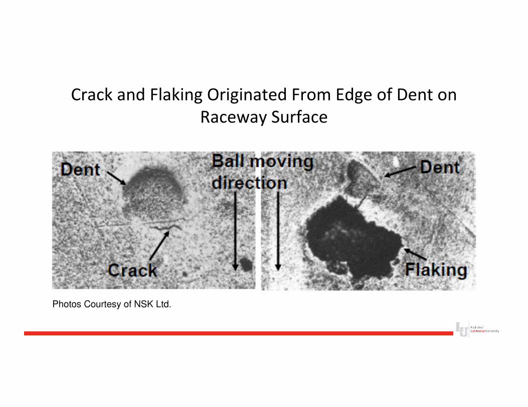
Crack and Flaking Originated From Edge of Dent on
Raceway Surface
Photos Courtesy of NSK Ltd.
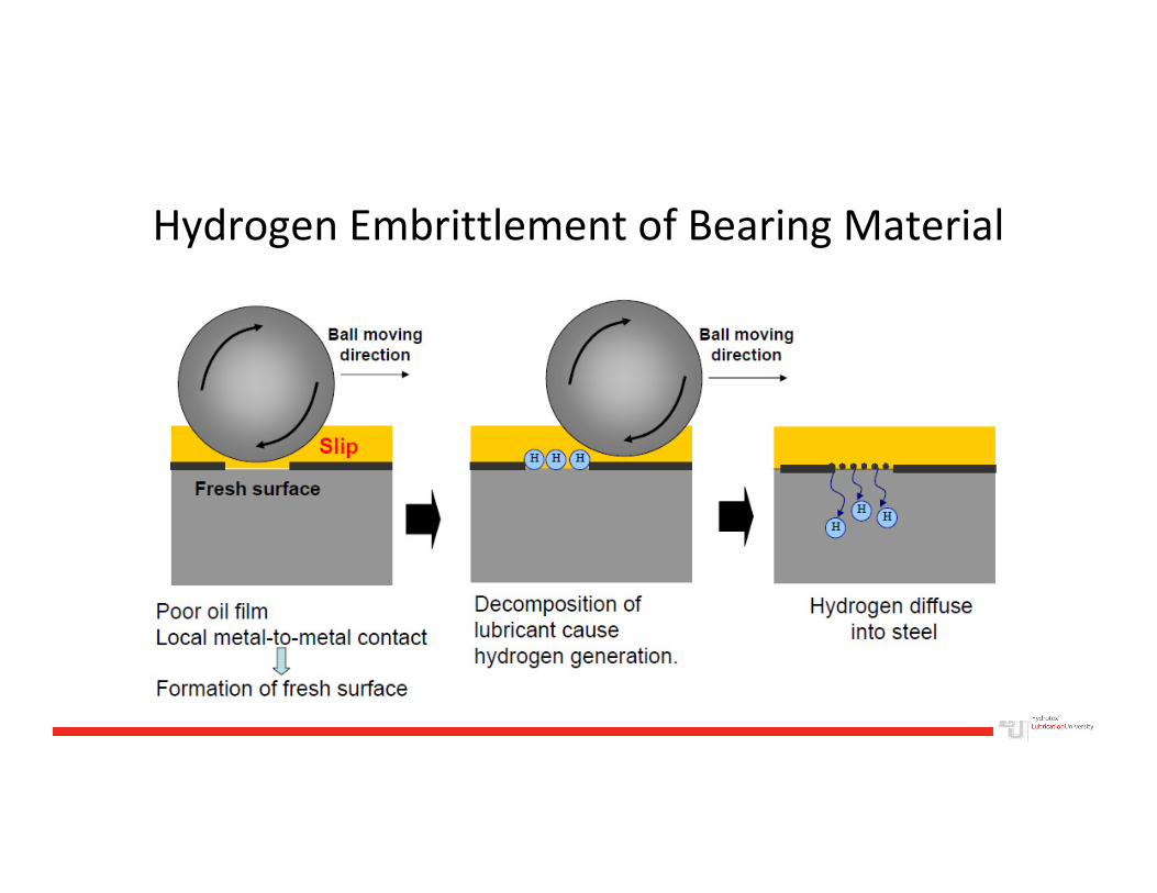
Hydrogen Embrittlement of Bearing Material
Micropitting PreventionLubrication Effects – Base Fluids
Selection of basestocks and additive chemistry also affect micropitting
•Tests have shown that micropitting resistance varies from lubricant to lubricant
•Oil solidifies under the high pressure generated in Elasto-hydrodynamic lubrication
•Tractional Stress on surface asperities is limited by the shear strength of the solidified oil
•Different basestocks have differences in solidification pressures and shear strength
Micropitting PreventionLubrication Effects – Base Fluids
• Polyglycols & Esters have low shear strength with
their flexible ether linkages – good lubricity.
– Polyglycols are very hygroscopic and have poor
compatibility with many seal materials and paints
– Esters are also hygroscopic
• Naphthenic mineral oils are too “stiff”, with compact
molecules that have a high traction coefficient
Micropitting PreventionLubrication Effects – Base Fluids
• Paraffinic mineral oils have open, elastic molecules
and low traction coefficients (good lubricity)
– Good Additive solubility
– Poor demulsibility (compared to PAOs and Group IIIs)
– Mineral oils contain numerous contaminates that may
cause deposits and surface corrosion (corrosive pitting)
under EHL pressures and heat
Micropitting PreventionLubrication Effects – Base Fluids
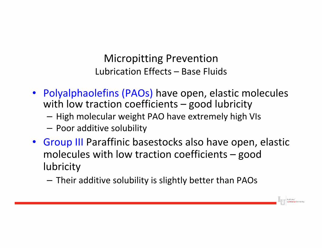
• Polyalphaolefins (PAOs) have open, elastic molecules with low traction coefficients – good lubricity – High molecular weight PAO have extremely high VIs
– Poor additive solubility
• Group III Paraffinic basestocks also have open, elastic molecules with low traction coefficients – good lubricity
– Their additive solubility is slightly better than PAOs
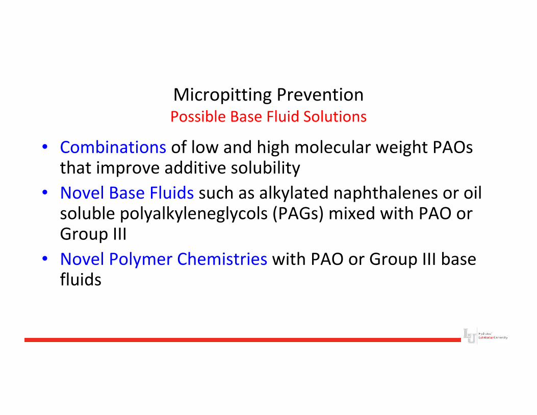
Micropitting PreventionPossible Base Fluid Solutions
• Combinations of low and high molecular weight PAOs that improve additive solubility
• Novel Base Fluids such as alkylated naphthalenes or oil soluble polyalkyleneglycols (PAGs) mixed with PAO or Group III
• Novel Polymer Chemistries with PAO or Group III base fluids
Micropitting Prevention
Lubrication Effects - Additives
Field testing has shown widely varying results for the
influence of sulfur-phosphorus (S-P) extreme pressure
additives on micropitting
Some S-P additives appear to promote while others
protect against Micropitting
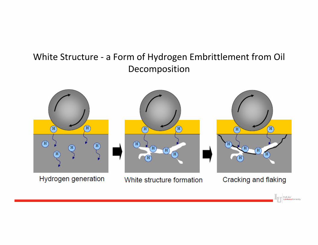
White Structure - a Form of Hydrogen Embrittlement from Oil
Decomposition
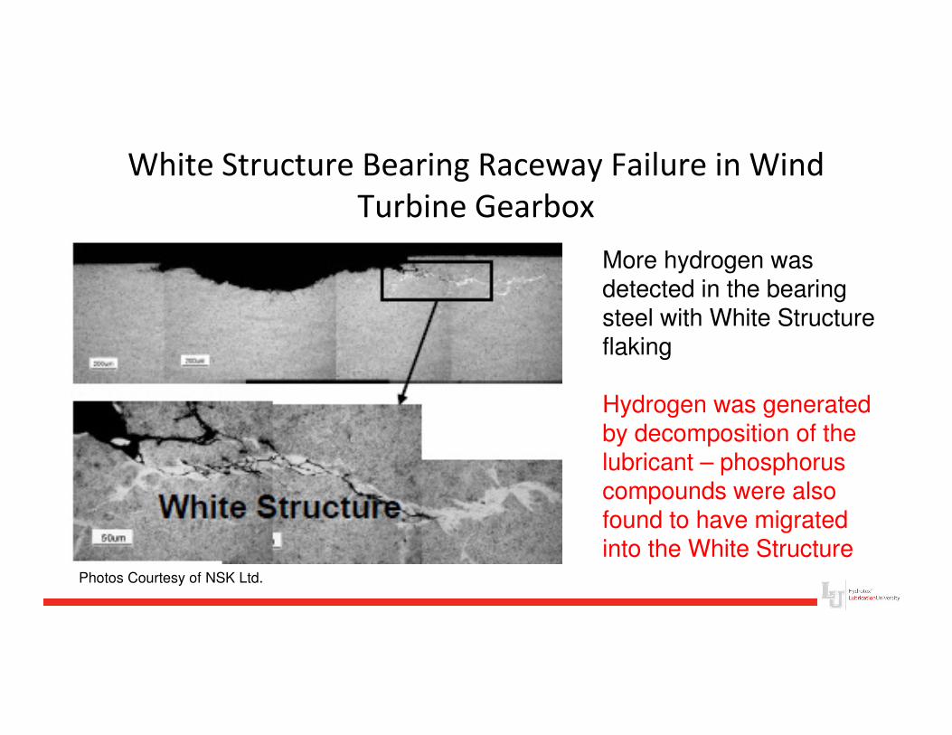
White Structure Bearing Raceway Failure in Wind
Turbine Gearbox
Photos Courtesy of NSK Ltd.
More hydrogen was detected in the bearing steel with White Structure flaking
Hydrogen was generated by decomposition of the lubricant – phosphorus compounds were also found to have migrated into the White Structure
Micropitting Prevention
Possible Additive Solutions
• Additive activation temperature appears to be a factor in determining micropitting performance
• Thermal stability and durability of the S-P additives –resistance to chemical decomposition of the additive as temperature increases also affects the micropitting performance of the additives
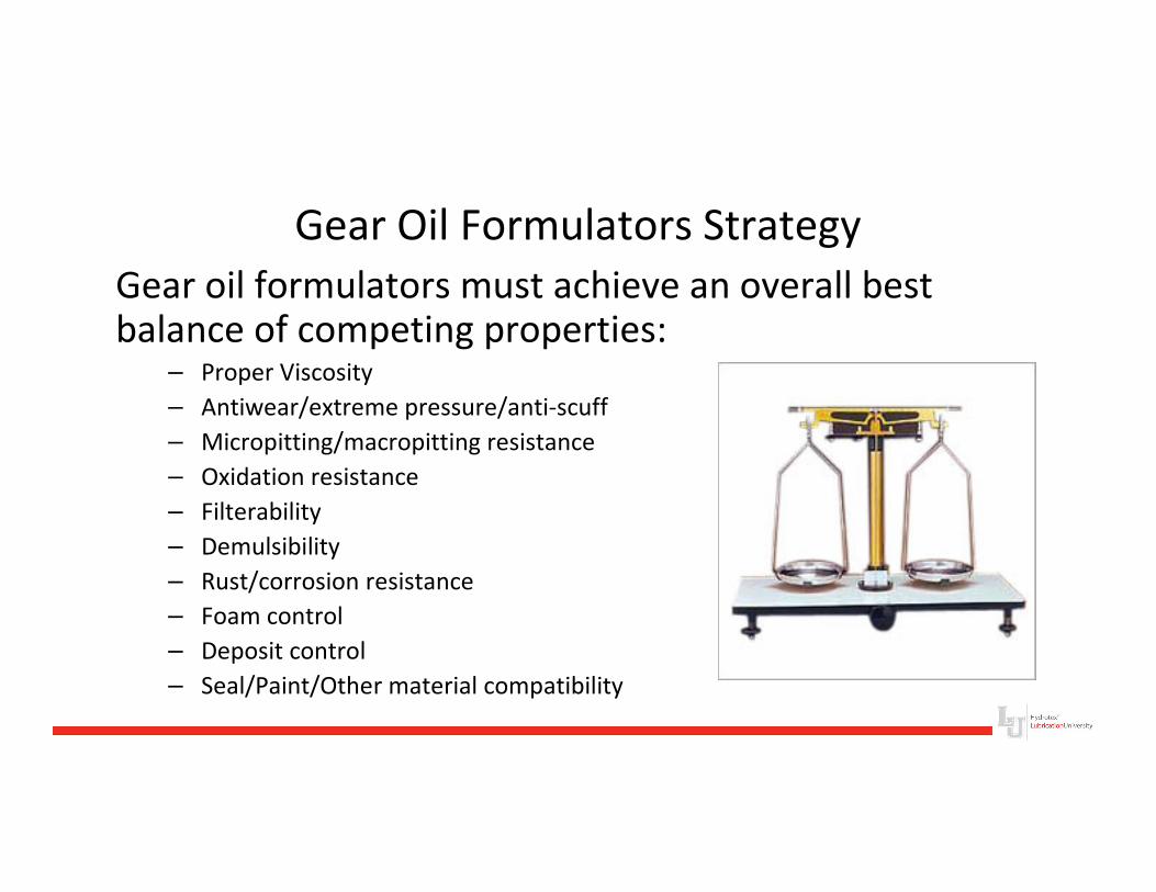
Gear Oil Formulators Strategy
Gear oil formulators must achieve an overall best balance of competing properties:
– Proper Viscosity
– Antiwear/extreme pressure/anti-scuff
– Micropitting/macropitting resistance
– Oxidation resistance
– Filterability
– Demulsibility
– Rust/corrosion resistance
– Foam control
– Deposit control
– Seal/Paint/Other material compatibility
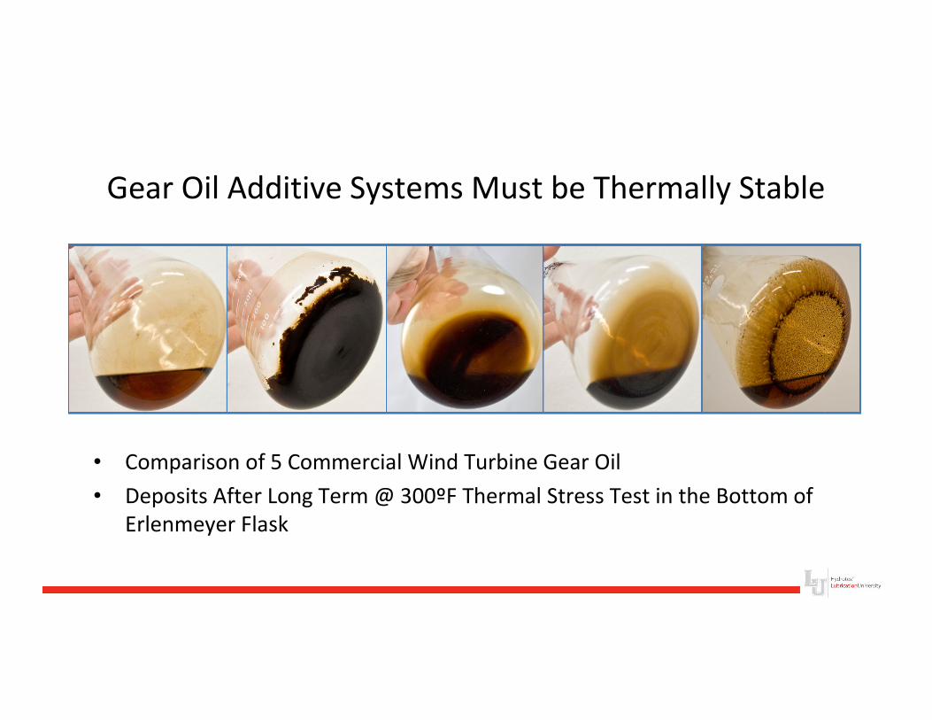
Gear Oil Additive Systems Must be Thermally Stable
• Comparison of 5 Commercial Wind Turbine Gear Oil
• Deposits After Long Term @ 300ºF Thermal Stress Test in the Bottom of
Erlenmeyer Flask
Thermal Decomposition of Gear Oil
• Increased filter plugging
• Increased viscosity
• Loss of boundary lubrication
• Promotion of hydrogen embrittlement
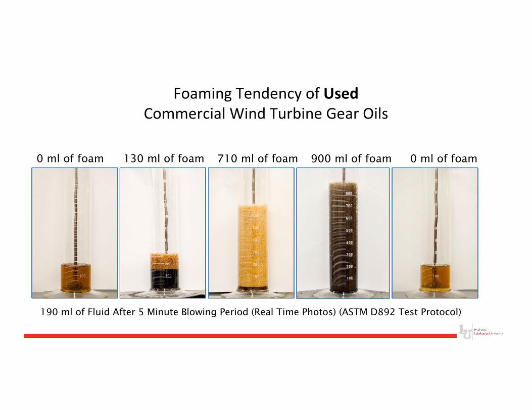
Foaming Tendency of Used
Commercial Wind Turbine Gear Oils
0 ml of foam0 ml of foam 130 ml of foam 900 ml of foam710 ml of foam
190 ml of Fluid After 5 Minute Blowing Period (Real Time Photos) (ASTM D892 Test Protocol)
Gear Oil Foaming
• Loss of oil film in contact zone
• Oil pump cavitation
• Higher operating temperatures
• Gear box leaking
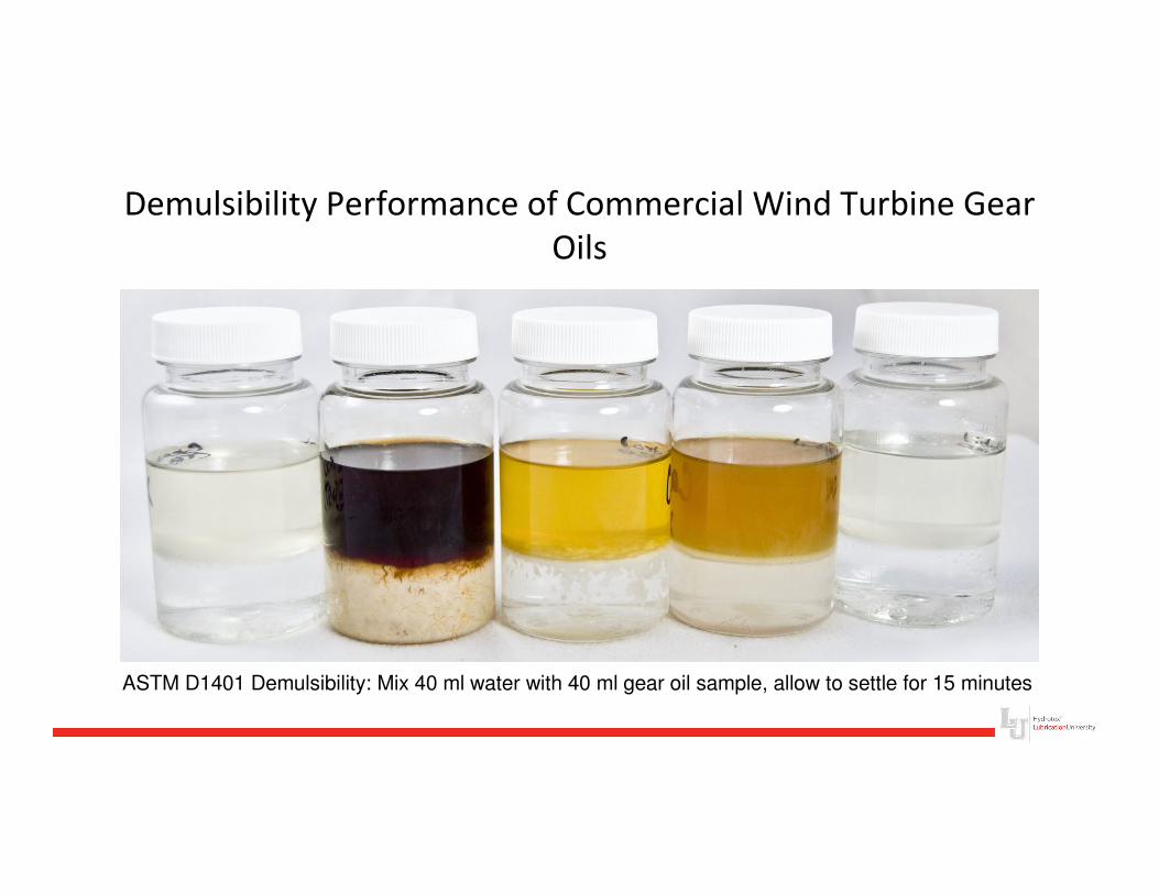
Demulsibility Performance of Commercial Wind Turbine Gear
Oils
ASTM D1401 Demulsibility: Mix 40 ml water with 40 ml gear oil sample, allow to settle for 15 minutes
Oil and Water Mixtures
• Loss of oil film in contact zone
• Promotion of hydrogen embrittlement
• Additive depletion or inactivation
• Rust
• Filter plugging
• Greater suspension of wear particles in emulsion
SUMMARY: Preventing Micropitting Is the First Step
to Extend Gear Box Life
• Micropitting affects both gear and bearing surfaces
• Both foaming and water emulsions disrupt the oil film between rolling and sliding surfaces
• Thermal stability and thermal durability of the basestock-additive combination is critical
• Keeping gear surfaces free of deposits allows the additive chemistry to work as designed and also reduces heat generation and retention