Embed Size (px)
Citation preview
FROST H E A V E INDUCED MECHANICS
OF BURIED P I P E L I N E S
By A. P. S. Selvadurai, I Member, ASCE, and S. B. Shinde, 2 Member, ASCE
ABSTRACT: This paper examines the problem of the flexural interaction between a long-distance buried pipeline embedded in a soil medium that experiences dif- ferential frost heave. The modeling takes into consideration the interaction at a transition zone between a frozen region and a frost-susceptible region that expe- riences a time-dependent growth of a frost bulb around the buried pipeline. The heave that accompanies the development of a frost bulb induces the soil-pipeline interaction process. The analysis focuses on the development of a computational scheme that addresses the three-dimensional nature of the soil-pipeline interaction problem, the creep susceptibility of the frozen region, and a prescribed time- and stress-dependent heave in an evolving frost bulb zone. The numerical results pre- sented in the paper illustrate the influence of the heave process and the creep behavior of the frozen soil on the displacements and stresses in the buried pipeline.
INTRODUCTION
Buried pipelines are constructed geotechnical facilities that are used quite extensively to t ransport mater ia ls such as oil, natural gas, coal slurries, mine tailings, and water. Such pipelines are designed, constructed, and main- tained according to s tandards and codes that ensure safe and economical operat ion during their service life. In contrast to above-ground pipelines, the structural analysis and design of a bur ied pipeline should take into consideration the mutual interact ion be tween the pipeline and the surround- ing soil. These interactions can be induced by a variety of effects including service loads such as deformat ions due to t empera tu re and pressure; loadings of a geotechnical nature , including ground subsidence, frost heave, and thaw settlement; the action of external loadings, be rm construction, roadway traffic loads, ear thquake loads, landslides (both onshore and submarine) relief due to excavations and pipel ine f lotat ion due to soil inundat ion (Ar- iman et al. 1979; "Lis t" 1980; Shibata et al. 1980; Smith 1981; Selvadurai and Lee 1981, 1982; Pickell 1983; Nixon et al. 1983; Ladanyi and Lemaire 1984; Jeyapalan 1985; Selvadurai 1985, 1988, 1991; Selvadurai and Pang 1988; Selvadurai et a|. 1983, 1990; Parmuzin et al. 1988). In the model ing of soil-pipeline interaction problems, adequate consideration should be given to the various t ime-dependent thermomechanica l phenomena associated with the mechanical behavior of soil, the structural response of the pipe, and the soil-pipeline interface that t ransmits actions between the buried pipeline and the surrounding soil. A variety of analytical and computat ional procedures, of varying complexi ty, can be deve loped for the analysis of a soil-pipeline interact ion problem. These range from simplified models of
~Prof. and Chmn., Dept. of Civ. Engrg. and Appl. Mech., McGill Univ., 817 Sherbrooke St. West, Montreal, Quebec, Canada H3A2K6.
2Engr., Res. and Tech. Div., ESSO Resour. Canada Ltd., 3535 Research Road NW, Calgary, Alberta, Canada T2L 2K8.
Note. Discussion open until May 1, 1994. To extend the closing date one month, a written request must be filed with the ASCE Manager of Journals. The manuscript for this paper was submitted for review and possible publication on October 7, 1992. This paper is part of the Journal of Geotechnical Engineering, Vol. 119, No. 12, December, 1993. �9 ISSN 0733-9410/93/0012-1929/$1.00 + $.15 per page. Paper No. 3445.
1929
J. Geotech. Engrg., 1993, 119(12): 1929-1951
Dow
nloa
ded
from
asc
elib
rary
.org
by
McG
ill U
nive
rsity
on
12/0
3/15
. Cop
yrig
ht A
SCE
. For
per
sona
l use
onl
y; a
ll ri
ghts
res
erve
d.
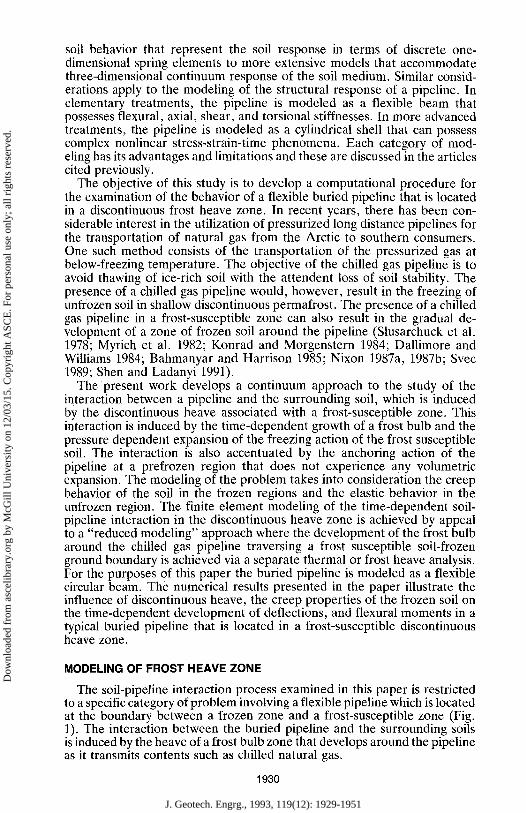
soil behavior that represent the soil response in terms of discrete one- dimensional spring elements to more extensive models that accommodate three-dimensional continuum response of the soil medium. Similar consid- erations apply to the modeling of the structural response of a pipeline. In elementary treatments, the pipeline is modeled as a flexible beam that possesses flexural, axial, shear, and torsional stiffnesses. In more advanced treatments, the pipeline is modeled as a cylindrical shell that can possess complex nonlinear stress-strain-time phenomena. Each category of mod- eling has its advantages and limitations and these are discussed in the articles cited previously.
The objective of this study is to develop a computational procedure for the examination of the behavior of a flexible buried pipeline that is located in a discontinuous frost heave zone. In recent years, there has been con- siderable interest in the utilization of pressurized long distance pipelines for the transportation of natural gas from the Arctic to southern consumers. One such method consists of the transportation of the pressurized gas at below-freezing temperature. The objective of the chilled gas pipeline is to avoid thawing of ice-rich soil with the attendent loss of soil stability. The presence of a chilled gas pipeline would, however, result in the freezing of unfrozen soil in shallow discontinuous permafrost. The presence of a chilled gas pipeline in a frost-susceptible zone can also result in the gradual de- velopment of a zone of frozen soil around the pipeline (Slusarchuck et al. 1978; Myrich et al. 1982; Konrad and Morgenstern 1984; Dallimore and Williams 1984; Bahmanyar and Harrison 1985; Nixon 1987a, 1987b; Svec 1989; Shen and Ladanyi 1991).
The present work develops a continuum approach to the study of the interaction between a pipeline and the surrounding soil, which is induced by the discontinuous heave associated with a frost-susceptible zone. This interaction is induced by the time-dependent growth of a frost bulb and the pressure dependent expansion of the freezing action of the frost susceptible soil. The interaction is also accentuated by the anchoring action of the pipeline at a prefrozen region that does not experience any volumetric expansion. The modeling of the problem takes into consideration the creep behavior of the soil in the frozen regions and the elastic behavior in the unfrozen region. The finite element modeling of the time-dependent soil- pipeline interaction in the discontinuous heave zone is achieved by appeal to a "reduced modeling" approach where the development of the frost bulb around the chilled gas pipeline traversing a frost susceptible soil-frozen ground boundary is achieved via a separate thermal or frost heave analysis. For the purposes of this paper the buried pipeline is modeled as a flexible circular beam. The numerical results presented in the paper illustrate the influence of discontinuous heave, the creep properties of the frozen soil on the time-dependent development of deflections, and flexural moments in a typical buried pipeline that is located in a frost-susceptible discontinuous heave zone.
MODELING OF FROST HEAVE ZONE
The soil-pipeline interaction process examined in this paper is restricted to a specific category of problem involving a flexible pipeline which is located at the boundary between a frozen zone and a frost-susceptible zone (Fig. 1). The interaction between the buried pipeline and the surrounding soils is induced by the heave of a frost bulb zone that develops around the pipeline as it transmits contents such as chilled natural gas.
1930
J. Geotech. Engrg., 1993, 119(12): 1929-1951
Dow
nloa
ded
from
asc
elib
rary
.org
by
McG
ill U
nive
rsity
on
12/0
3/15
. Cop
yrig
ht A
SCE
. For
per
sona
l use
onl
y; a
ll ri
ghts
res
erve
d.
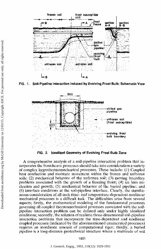
FIG. 1.
frozen soil frost susceptible _ L. soil
~ ~ ~ - ~ ~ ~ f r os t - r '~B I r .~A /-~h_ov ̂ section section / J . . . . . J . . . . . ~_~ = ~ A-A j B-B
~ ' ' . . . . - I : - ' . . : ~ :, : ' i ~ F, . - - : : - ~" .L-: ' :4; -:_-5~" " ' - : _~ ":" ~'~ ~ --'."-:'---~ ."..:L,. . ' - ~ - ~ - . . -
' ! Ipipe,nel : / f :iii--: - . : _ ~ . , . , . ' . ,~ ,: . ' . .
� 9 1 4 9
" ~ ~ ~ . ~,- ' / . . ' ~ - - t f r o s t ~ , v . i : " ' :Ibu,b :
I . B
So i l -P ipe l i ne In teract ion Induced by Evo lv ing Frost Bulb: Schemat ic V iew
#(;L--'I
c h i l l e d gas ~ . ~ Y j ~ ] " ' / . ~ . pipeline
. " ' . 1 " " [ . . .
: i . " ' ' " ' * ' I , " " " . ~ ( T ~ ' "," " " ' ~ ' " "." unfrozen so i l
~ ~ ~ ~ ~ (frost susceptible) :
. . . . " * . . ,L_ , . , . ; . .__ ; :~ : ;~ . : . : . ; J �9 ' e v o l v i n g frost �9 . . . �9 , -.. ' . . .
" bulb boundory , . . . �9 -
, . . . ' = . . . . . . . : ' . . ' " . " . . :
" . . . . " , / . . " ' . . . ' - 5 . , - .
I I I I I
FIG. 2. Ideal ized G e o m e t r y of Evolv ing Frost Bulb Z o n e
A comprehensive analysis of a soil-pipeline interaction problem that in- corporates the frost-heave processes should take into consideration a variety of complex hygrothermomechanical processes. These include: (l) Coupled heat conduction and moisture movement within the frozen and unfrozen soils; (2) mechanical behavior of the unfrozen soil; (3) moving boundary problems associated with the growth of a freezing front; (4) ice lens nu- cleation and growth; (5) mechanical behavior of the buried pipeline; and (6) interface conditions at the soil-pipeline interface. Clearly, the simulta- neous consideration of all such time- and temperature-dependent nonlinear mechanical processes is a difficult task. The difficulties arise from several aspects; firstly, the mathematical modeling of the fundamental processes governing all coupled thermomechanical processes associated with the soil- pipeline interaction problem can be defined only under highly idealized conditions; secondly, the solution of realistic three-dimensional soil-pipeline interaction problems that incorporate the time-dependent and nonlinear coupled processes (indicated by the aforementioned enumerated processes) requires an inordinate amount of computational rigor; thirdly, a buried pipeline is a long-distance geotechnical structure where a multitude of soil
1931
J. Geotech. Engrg., 1993, 119(12): 1929-1951
Dow
nloa
ded
from
asc
elib
rary
.org
by
McG
ill U
nive
rsity
on
12/0
3/15
. Cop
yrig
ht A
SCE
. For
per
sona
l use
onl
y; a
ll ri
ghts
res
erve
d.
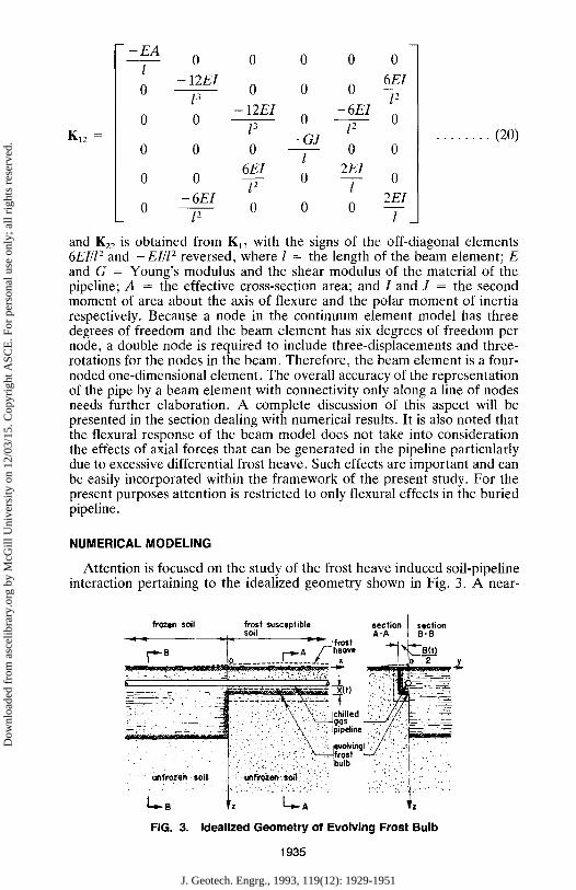
types can be encountered along its length. The accurate determination of the in situ hygrothermomechanical characteristics of soils that are necessary for the solution of soil-pipeline interaction problems is a daunting task. Consequently, plausible approximations need to be made for the solution of soil-pipeline interaction problem particularly in relation to effects of frost heave. In this context, a convenient simplification is to assume that the heat and moisture movement and the frost region generation can be considered as separate "thermal," "hygrothermal," and "phase transformation" proc- esses, which are independent of the mechanical processes. This assumption is certainly open to criticism; nonetheless it provides a useful first approx- imation to the treatment of an otherwise complex problem. In this study it is assumed that the development of a frost bulb around the buried pipeline is not influenced by the mechanical response of the frozen or frost-suscep- tible soils. The geometry and development of the frost bulb around the pipeline is specified by a separate analysis. An example of such an analysis that approximates the developing frost bulb as a zone with a rectangular cross section, is given by Nixon (1987a, b). In this treatment, the cross section of the frost bulb can be represented by a rectangular region that is defined by a time-dependent width B ( t ) and a time-dependent depth X ( t ) below the base of the pipeline (Fig. 2). The analysis by Nixon (1987b) provides empirical relationships of the type
x ( t ) : X o ( t ) ~ x . . . . . . . . . . . . . . . . . . . . . . . . . . . . . . . . . . . . . . . . . . . . . . (1)
B( t ) = Bo(t ) TM . . . . . . . . . . . . . . . . . . . . . . . . . . . . . . . . . . . . . . . . . . . . . . (2)
where X0, B0, nqx, and ~qB are constants, which depend on the thermal and frost susceptibility characteristics of the soils. It is indeed possible to specify alternative frost bulb geometries by examining the hygrothermal-phase transformation problems in their entirety. In view of the primary objectives of examining the role of the frost heave in the soil-pipeline interaction it is sufficient to restrict the studies to the methodologies just described. It must also be noted that the processes of thaw around a frost heave zone due to removal of the chilled gas has important consequences on the mechanics of a buried pipeline during subsequent refreezing. This problem is, however, beyond the scope of the present study, which mainly focuses on a persistent supply of chilled gas to allow the continual evolution of the frost heave zone.
CONSTITUTIVE MODELING
Several different types of constitutive responses are necessary for the reduced modeling of the soil-pipeline interaction problem. These include the volumetric expansion of the frost-susceptible material within a frost bulb region, the creep behavior of the frozen soil, and the mechanical behavior of soils in the unfrozen region. The constitutive models are formulated by adopting an incremental small strain formulation, such that, where appro- priate, the total incremental strain in the soil medium is composed of the volumetric strain due to the freezing action in the frost susceptible soil (d~l) , the elastic strain (d~[~ 1) and the creep strain [cl (ds i j ) , i.e.,
deq = dei(; ') + d ~ ) + de~; ) . . . . . . . . . . . . . . . . . . . . . . . . . . . . . . . . . . . (3)
Volumetric Strains In the frost-susceptible region around the pipeline, the volume change in
the soil occurs mainly as a result of the moisture movement and the for-
1932
J. Geotech. Engrg., 1993, 119(12): 1929-1951
Dow
nloa
ded
from
asc
elib
rary
.org
by
McG
ill U
nive
rsity
on
12/0
3/15
. Cop
yrig
ht A
SCE
. For
per
sona
l use
onl
y; a
ll ri
ghts
res
erve
d.
mation of ice lenses [see, e.g., Ice (1984) and Anderson et al. (1984)]. The process generally results in anisotropic volume change phenomena in which the ice lenses usually occur orthogonal to the direction of heat and moisture flow. In the ensuing treatment, however, it is assumed that the volumetric expansion within the frost bulb is isotropic. Also, the volumetric expansion is influenced by the "overburden pressure" within the frost bulb zone. The 2-D geothermal simulator (Nixon 1987a) analysis conducted by Nixon (1991) also provides an empirical estimate for the volumetric strain (e) that occurs within the frost bulb zone, i.e.,
e = e[ln(~r,,), X(t)] . . . . . . . . . . . . . . . . . . . . . . . . . . . . . . . . . . . . . . . . . . (4)
where % = the vertical total overburden stress at a desired depth. Since (3) is usually obtained as a result of fitting a model to specific computations applicable to frost-susceptible soils, limiting bounds have to be assigned for X(t) and ~,, i.e.,
x ( t M o , . . . . . . . . . . . . . . . . . . . . . . . . . . . . . . . . . . . . . . . . . . . . . . . (5a) . . . . . . . . . . . . . . . . . . . . . . . . . . . . . . . . . . . . . . . . . . . . . . . . ( 5 b )
where Xf = a limiting value of the depth of the frost bulb below the base of the pipeline and ~r~! and (r{i = limits for the total vertical stress. For isotropic frost induced volume expansion
d~}; ') = d e ~ i j . . . . . . . . . . . . . . . . . . . . . . . . . . . . . . . . . . . . . . . . . . . . . . . . (6)
where de = an incremental value of e. From (4) it is evident that
Oe(t, ~r~,) dX(t) + Oe de% (7) d e - ox(t) . . . . . . . . . . . . . . . . . . . . . . . . . . . . . . .
In the first term of (7), dX(t) indicates a change in the depth (below base of pipeline) of the rectangular frozen region. In conventional finite element analyses without adaptive mesh refinements, the finite discretization of ele- ments cannot allow for a change in X(t) in every time step. A possible way to accommodate this is to consider that a number of time steps are required to transform a region from an unfrozen to a frozen state. If m = the number of time steps considered, the incremental value of e(t, ~ ) will be
de(t, ~,,) - e(t , %) . . . . . . . . . . . . . . . . . . . . . . . . . . . . . . . . . . . . . . . . . . (8) m
instead o f (7). A l so t and ~,, in (8) are the current values o f t ime and ver t ica l stress during that increment.
Creep Behavior The creep behavior of frozen soil has been investigated very extensively
[see, e.g., Tsytovich (1975), Andersland and Anderson (1978), Ladanyi (1972), Ladanyi (1978), Phukan (1985), and Morgenstern (1981)]. In this study the creep behavior of the frozen soil is represented by the generalized power law relationship
(c) = 3 D dgij ~ B ~ ( , ~ ) ~ - ~,~,j . . . . . . . . . . . . . . . . . . . . . . . . . . . . . . . . . . . . . . (9)
where
1933
J. Geotech. Engrg., 1993, 119(12): 1929-1951
Dow
nloa
ded
from
asc
elib
rary
.org
by
McG
ill U
nive
rsity
on
12/0
3/15
. Cop
yrig
ht A
SCE
. For
per
sona
l use
onl
y; a
ll ri
ghts
res
erve
d.
(Yeff = (~ iD (T i D ) . . . . . . . . . . . . . . . . . . . . . . . . . . . . . . . . . . . . . . . . . (10)
1 o _ ( n ) (Tij ~ f f i j 3 (~kk~ij . . . . . . . . . . . . . . . . . . . . . . . . . . . . . . . . . . . . . . . . .
and B~ and n = the secondary creep pa ramete r and the creep exponent respectively.
Elastic Modeling It is assumed that the soil in the frozen region and the soil in the unfrozen
region can exhibit elastic responses that can be characterized by a homo- geneous isotropic linear elastic model. The incremental isotropic linear elas- tic stress-strain law can be represented by
&rq = Dijgtde~ ) . . . . . . . . . . . . . . . . . . . . . . . . . . . . . . . . . . . . . . . . . . . . (12)
Dijk~ = the elasticity tensor, which can be written as
Esvs Es (SikSj, + ~k~i,) . . . . . . . (13) Dok, = (1 + v,)(1 - 2v,) ~ij~kl -~ 2(1 + v,)
and Es and v~ = respectively the elastic modulus and Poisson's ratio. From (3), the incremental stress in (12) can be rewritten as
dgij = D#kldekt -- dPij . . . . . . . . . . . . . . . . . . . . . . . . . . . . . . . . . . . . . . (14)
where the incremental stress dPq due to volumetric expansion and creep is given by
dP,j = D,j~,[de~ ) + de~)l . . . . . . . . . . . . . . . . . . . . . . . . . . . . . . . . . . . . (15)
Pipeline Response The pipeline with a circular cross section is modeled as a one-dimensional
Bernoulli-Euler beam. The corresponding nodal deflections and nodal forces are given by
(UB) T = (~/1, U2, b/3, 01, 02, 03) . . . . . . . . . . . . . . . . . . . . . . . . . . . . . . . . (16) (PB) T = (P1, P2, P3, m l , mR, m3) . . . . . . . . . . . . . . . . . . . . . . . . . . . . . . (17)
respectively. The beam element stiffness matrix can be written as
[Kn K12] Ke -- LKr2 K22j . . . . . . . . . . . . . . . . . . . . . . . . . . . . . . . . . . . . . . . . . . (18)
where the submatrices are
_E• 0 0 0 0 0
0 12EI 0 0 0 6 EI l 3 l 2
12EI - 6 EI 0 0 0 0
l 3 l 2 GJ
o o o 5 - o o - 6 E I 4 E I
0 0 0 0 l 2 l
6 E l 4 EI 0 12 0 0 0 - - F _
K l l = . . . . . . . . . . . . . . . (19)
1934
J. Geotech. Engrg., 1993, 119(12): 1929-1951
Dow
nloa
ded
from
asc
elib
rary
.org
by
McG
ill U
nive
rsity
on
12/0
3/15
. Cop
yrig
ht A
SCE
. For
per
sona
l use
onl
y; a
ll ri
ghts
res
erve
d.
K12 =
- - E A
1
0
0 0 0 0
- 1 2 E l 0 0 0
l 3 - 1 2 E I - 6EI
0 0 0 l 3 l 2
- G J 0 0 0 0
l 6EI 2EI
0 0 0 l 2 l
- 6 E l 0 0 0 0
12
0
6El l 2
0 . . . . . . . . (20)
0
0
2EI
l
and K22 is obtained from Kn with the signs of the off-diagonal elements 6EI/l 2 and - EI/l 2 reversed, where l = the length of the beam element; E and G = Young's modulus and the shear modulus of the material of the pipeline; A = the effective cross-section area; and I and J = the second moment of area about the axis of flexure and the polar moment of inertia respectively. Because a node in the continuum element model has three degrees of freedom and the beam element has six degrees of freedom per node, a double node is required to include three-displacements and three- rotations for the nodes in the beam. Therefore, the beam element is a four- noded one-dimensional element. The overall accuracy of the representation of the pipe by a beam element with connectivity only along a line of nodes needs further elaboration. A complete discussion of this aspect will be presented in the section dealing with numerical results. It is also noted that the flexural response of the beam model does not take into consideration the effects of axial forces that can be generated in the pipeline particularly due to excessive differential frost heave. Such effects are important and can be easily incorporated within the framework of the present study. For the present purposes attention is restricted to only flexural effects in the buried pipeline.
N U M E R I C A L M O D E L I N G
Attention is focused on the study of the frost heave induced soil-pipeline interaction pertaining to the idealized geometry shown in Fig. 3. A near-
frozen soil frost susceptible section section s o i l A - A B - B
< < ; ' - ; ' - frost
I _J_o . . . . . . . . . . J . . . . . . .t___ , _LJo--s y
b . . . . . . . . ~ _ t ~--,., , ;:!IL~,~. :-~. _=~ - - ~ - - , ' . . . . . . . �9 : . . . . . - " ' h - - - ' ~ X ( t ) ~ ~ - - - - ~
" i' " -~. . ~ ~ ~ : ." ~..'ii -" ~ ~ L ~ _ ~ ' ' g a s " . .,~'. " . ~
. . ~ i . . . �9 . . . . . . . . : . . ~ - , - : - : . . _ . .
. , - ~ . : " ; . : " ~ - ~ - ~ f r o e t ~ L / ~ ' ~' ~ -'-: : '. J .
. . . . . . " " : - . i: '. Z--:-.):..". ?-:.:ii.;~ ! . , ,
L.-B ,, L._~
F I G . 3 . I d e a l i z e d G e o m e t r y o f E v o l v i n g F r o s t B u l b
1935
J. Geotech. Engrg., 1993, 119(12): 1929-1951
Dow
nloa
ded
from
asc
elib
rary
.org
by
McG
ill U
nive
rsity
on
12/0
3/15
. Cop
yrig
ht A
SCE
. For
per
sona
l use
onl
y; a
ll ri
ghts
res
erve
d.
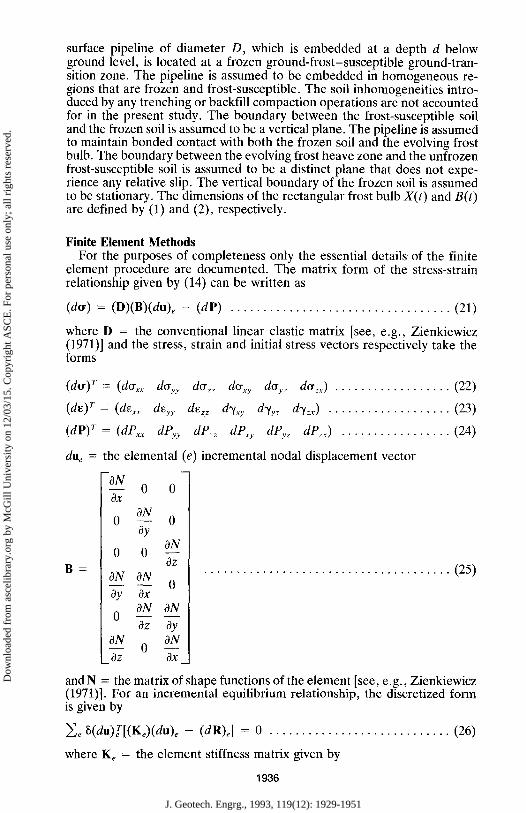
surface pipeline of diameter D, which is embedded at a depth d below ground level, is located at a frozen ground-frost-susceptible ground-tran- sition zone. The pipeline is assumed to be embedded in homogeneous re- gions that are frozen and frost-susceptible. The soil inhomogeneities intro- duced by any trenching or backfill compaction operations are not accounted for in the present study. The boundary between the frost-susceptible soil and the frozen soil is assumed to be a vertical plane. The pipeline is assumed to maintain bonded contact with both the frozen soil and the evolving frost bulb. The boundary between the evolving frost heave zone and the unfrozen frost-susceptible soil is assumed to be a distinct plane that does not expe- rience any relative slip. The vertical boundary of the frozen soil is assumed to be stationary. The dimensions of the rectangular frost bulb X(t) and B(t) are defined by (1) and (2), respectively.
Finite E lement Methods For the purposes of completeness only the essential details of the finite
element procedure are documented. The matrix form of the stress-strain relationship given by (14) can be written as
(dcr) = (D)(B)(du)e - ( d P ) . . . . . . . . . . . . . . . . . . . . . . . . . . . . . . . . . . (21)
where D = the conventional linear elastic matrix [see, e.g., Zienkiewicz (1971)] and the stress, strain and initial stress vectors respectively take the forms
(do') T = (dffxx doyy d%_. d%y dcryz dcr.x) . . . . . . . . . . . . . . . . . . (22)
(de) r = (d~x, deyy de= d%.v dyyz d%x) . . . . . . . . . . . . . . . . . . . (23)
(dP) T = (dPxx dPvy dnzz dPxy dPv._ dP~) . . . . . . . . . . . . . . . . . (24)
due = the elemental (e) incremental nodal displacement vector
-aN -~x o o
o ~ ay
ON o o -dTz
ON ON 0
ay ax ON ON
0 az ay
aN 0 aN Oz Ox
B = . . . . . . . . . . . . . . . . . . . . . . . . . . . . . . . . . . . . . . (25)
and N = the matrix of shape functions of the element [see, e.g., Zienkiewicz (1971)]. For an incremental equilibrium relationship, the discretized form is given by
Ze ~(du) Te[(Ke)(du)e - (dR)e] = 0 . . . . . . . . . . . . . . . . . . . . . . . . . . . . (26)
where K e = the element stiffness matrix given by
1936
J. Geotech. Engrg., 1993, 119(12): 1929-1951
Dow
nloa
ded
from
asc
elib
rary
.org
by
McG
ill U
nive
rsity
on
12/0
3/15
. Cop
yrig
ht A
SCE
. For
per
sona
l use
onl
y; a
ll ri
ghts
res
erve
d.
f Ke : L (B) T(D) (B) d O . . . . . . . . . . . . . . . . . . . . . . . . . . . . . . . . . . . . . (27)
e
and dRe = the incremental load vector due to the effect of volumetric strains and creep strains.
Incremental Load Vector If (7) is integrated from to to (to +mdt ) we can write
c~[/o + mdt, (~L,)m] = 1 2 e~[ti, (~r~.)i] . . . . . . . . . . . . . . . . . . . . . . . . . (28) m i = l
with a(to, [cr~.]o) = 0. Therefore , the volumetric strain in this region is achieved in an average sense. The incremental volumetric strain vector is then given as
(d~)(~,) _ da(t, cry.) (1, 1, 1 0, 0, 0) T . . . . . . . . . . . . . . . . . . . . . . . . . . . (29) 3
where da(t, cry,) is given by (8). For the creep strain vector, we have from (9)
3B~ (de)('~ = 2 (M' ) (~176 d t . . . . . . . . . . . . . . . . . . . . . . . . . . . . . . . . (30)
where the definitions of (d~ M) and a follow
M 1 =
- 2 1 1 0 0
3 3 1 2 1
0 0 0 - ~ 5 3
1 1 2 3 3 3 0 0 0
0 0 0 2 0 0
0 0 0 0 2 0
_ 0 0 0 0 0 2
0
. . . . . . . . . . . . . . . . . . . . . . . . . . (31)
Therefore, the incremental strain due to volumetric expansion and creep is
1 1 0 + 0 0
3B,~ (M,)(w)r d t . . . . . . . . (32) [d~"q + [&"~] - - -
The incremental load dRe given in (26) can be written as
(dR)e = ~ ; (B)T(D){[de (~')] +[de(")]} dO . . . . . . . . . . . . . . . . . . . . . . (33)
1937
J. Geotech. Engrg., 1993, 119(12): 1929-1951
Dow
nloa
ded
from
asc
elib
rary
.org
by
McG
ill U
nive
rsity
on
12/0
3/15
. Cop
yrig
ht A
SCE
. For
per
sona
l use
onl
y; a
ll ri
ghts
res
erve
d.
5.0
M m a x
q a ~
�9 ~. 0
3 . 0
~ . 0
1 .0
~. - .0
=3!
= Beam element model ( 4 do~lo ) nodes -" Solid element model (8 .,~.) & Shell element model (4 do,~l, ) nodes
2a
EbI ~ . !~" ~ �9 j . ~ .
~ E , ,v~
0 . 0 -" . . . . . . . . . . . . . . . . .
tO ' tO ~ I0 ~" I0 1
Eb I
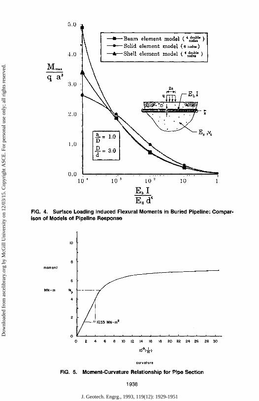
FIG. 4. Surface Loading Induced Flexural Moments in Buried Pipeline: Compar- ison of Models of Pipeline Response
moment
MN-m
6
Mp - - - -
4
2
0 0 2 4 6 S ]0 12 14 16 18 20 22 24 26 28 30
10"3(--~-)
curvature
FIG. 5. Moment-Curvature Relationship for Pipe Section
1938
J. Geotech. Engrg., 1993, 119(12): 1929-1951
Dow
nloa
ded
from
asc
elib
rary
.org
by
McG
ill U
nive
rsity
on
12/0
3/15
. Cop
yrig
ht A
SCE
. For
per
sona
l use
onl
y; a
ll ri
ghts
res
erve
d.
COrn
40m
pipeline . ,
+ Z
40m
.~-y
Om
IOrn
40m
i
Z
40m
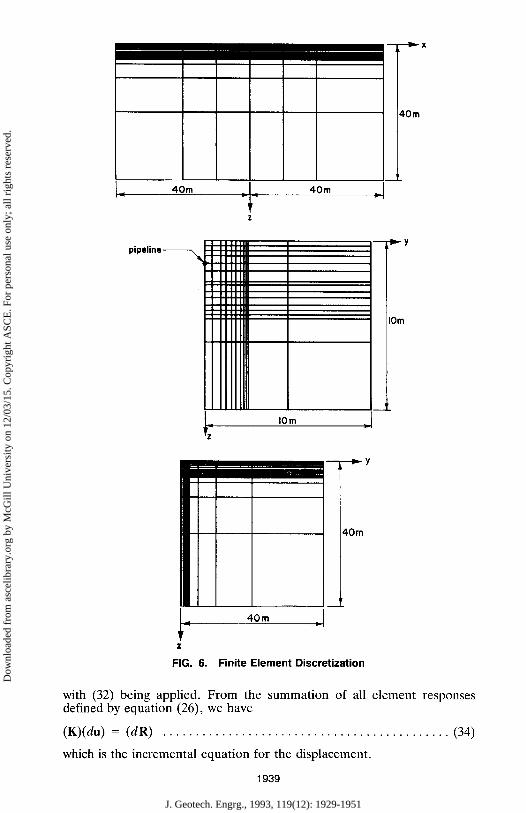
FIG. 6. Finite Element Discretization
with (32) being applied. From the summation of all element responses defined by equation (26), we have
(K)(du) = (dR) . . . . . . . . . . . . . . . . . . . . . . . . . . . . . . . . . . . . . . . . . . . . (34)
which is the incremental equation for the displacement.
1939
J. Geotech. Engrg., 1993, 119(12): 1929-1951
Dow
nloa
ded
from
asc
elib
rary
.org
by
McG
ill U
nive
rsity
on
12/0
3/15
. Cop
yrig
ht A
SCE
. For
per
sona
l use
onl
y; a
ll ri
ghts
res
erve
d.
25 YEARS - - ~
15 YEARS--D
10 YEARS--~
5 YEARS --#
2 YEARS - - 0
I YEAR--I
.5 YEARS --k
0,60
0.50
-0.40
0.30
0.20
S l l l ' f a c e D i s p l a c e m e n t (m)
0,25
0.20
0.15
0.10
0.05
0.00 0 5 10 15
I - 5 0
I l - 4 0 - 3 0
Distance along Pipeline (m)
-20 -10 10 2'0 3~0 40 510
-10.10
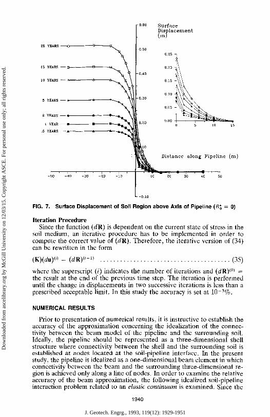
FIG. 7. Surface Displacement of Soil Region above Axis of Pipeline (B; = 0)
Iteration Procedure Since the function (dR) is dependent on the current state of stress in the
soil medium, an iterative procedure has to be implemented in order to compute the correct value of (dR). Therefore, the iterative version of (34) can be rewritten in the form
(K)(du) (/) = (dR) (~-') . . . . . . . . . . . . . . . . . . . . . . . . . . . . . . . . . . . . . . . (35)
where the superscript (i) indicates the number of iterations and (dR) (~ = the result at the end of the previous time step. The iteration is performed until the change in displacements in two successive iterations is less than a prescribed acceptable limit. In this study the accuracy is set at 10-~%.
NUMERICAL RESULTS
Prior to presentation of numerical results, it is instructive to establish the accuracy of the approximation concerning the idealization of the connec- tivity between the beam model of the pipeline and the surrounding soil. Ideally, the pipeline should be represented as a three-dimensional shell structure where connectivity between the shell and the surrounding soil is established at nodes located at the soil-pipeline interface. In the present study, the pipeline is idealized as a one-dimensional beam element in which connectivity between the beam and the surrounding three-dimensional re- gion is achieved only along a line of nodes. In order to examine the relative accuracy of the beam approximation, the following idealized soil-pipeline interaction problem related to an elastic continuum is examined. Since the
1940
J. Geotech. Engrg., 1993, 119(12): 1929-1951
Dow
nloa
ded
from
asc
elib
rary
.org
by
McG
ill U
nive
rsity
on
12/0
3/15
. Cop
yrig
ht A
SCE
. For
per
sona
l use
onl
y; a
ll ri
ghts
res
erve
d.
25 YEARS--O--- O
15 YEARS--~-- C
10 YEARS--,~ A
5 YEARS--m
2 YEARS--~ I YEAR--~
.5 Y E A R S - - ~
-0.80
- 0.50
Pipeline Displacement (m)
f 0.25 0.20 0.40
0.15
0 .10 0.30
0.05
0 .20 0 .00 i T
0 5 I0 15
Distance along Pipeline (In)
- 5 0 - 4 0 - 3 0 - 2 0 - 1 0 I 10 20 30 40 50
~- -0.10
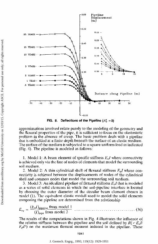
FIG. 8. Deflections of the Pipeline (B~ =0)
approximations involved relate purely to the modeling of the geometry and the flexural properties of the pipe, it is sufficient to focus on the elastostatic problem in the absence of creep. The basic problem deals with a pipeline that is embedded at a finite depth beneath the surface of an elastic medium. The surface of the medium is subjected to a square uniform load as indicated (Fig. 4). The pipeline is modeled as follows:
1. Model 1: A beam element of specific stiffness EbI where connectivity is achieved only via the line of nodes of elements that model the surrounding soil medium.
2. Model 2: A thin cylindrical shell of flexural stiffness EbI where con- nectivity is achieved between the displacements of nodes of the cylindrical shell and common nodes that model the surrounding soil medium.
3. Model 3: An idealized pipeline of flexural stiffness Eft that is modeled as a series of solid elements in which the soil-pipeline interface is located by choosing the outer diameter of the circular beam element chosen in model (1). The equivalent elastic moduli used to model the solid elements composing the pipeline are determined from the relationship
Ee q = (EbI)pipeli.~ from model 1 (1)p~pe from model 2 . . . . . . . . . . . . . . . . . . . . . . . . . . . . . . . (36)
The results of the computations shown in Fig. 4 illustrates the infuence of the relative stiffness between the pipeline and the soil defined by R ( = EbI/ Es d4) on the maximum flexural moment induced in the pipeline. These
1941
J. Geotech. Engrg., 1993, 119(12): 1929-1951
Dow
nloa
ded
from
asc
elib
rary
.org
by
McG
ill U
nive
rsity
on
12/0
3/15
. Cop
yrig
ht A
SCE
. For
per
sona
l use
onl
y; a
ll ri
ghts
res
erve
d.
25 YEARS 0 15 YEARS E] 10 YEARS
5 YEARS 2 YEARS I YEAR -"
0.5 YEARS A
i 0 .80 Mma x
Mp
. 0 .60
0.40
- 4 0 - 3 0 = - 2 0 - 1 0
0.20
D i s t a n c e along Pipeline (m)
30 40
-0,20
-0.40
- 0 . 6 0
- 0 . 8 0 J
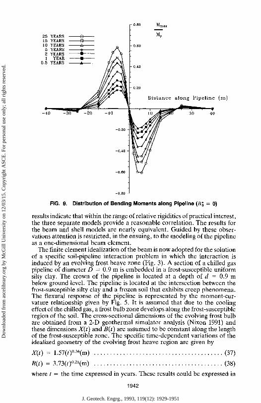
FIG. 9. Distribution of Bending Moments along Pipeline (B~ = 0)
results indicate that within the range of relative rigidities of practical interest, the three separate models provide a reasonable correlation. The results for the beam and shell models are nearly equivalent. Guided by these obser- vations attention is restricted, in the ensuing, to the modeling of the pipeline as a one-dimensional beam element.
The finite element idealization of the beam is now adopted for the solution of a specific soil-pipeline interaction problem in which the interaction is induced by an evolving frost heave zone (Fig. 3). A section of a chilled gas pipeline of diameter D = 0.9 m is embedded in a frost-susceptible uniform silty clay. The crown of the pipeline is located at a depth of d = 0.9 m below ground level. The pipeline is located at the intersection between the frost-susceptible silty clay and a frozen soil that exhibits creep phenomena. The flexural response of the pipeline is represented by the moment-cur- vature relationship given by Fig. 5. It is assumed that due to the cooling effect of the chilled gas, a frost bulb zone develops along the frost-susceptible region of the soil. The cross-sectional dimensions of the evolving frost bulb are obtained from a 2-D geothermal simulator analysis (Nixon 1991) and these dimensions X(t) and B(t) are assumed to be constant along the length of the frost-susceptible zone. The specific time-dependent variations of the idealized geometry of the evolving frost heave region are given by
X(t) = 1.57(t)~ . . . . . . . . . . . . . . . . . . . . . . . . . . . . . . . . . . . . . . . . (37)
B(t) = 3.73(t)~ . . . . . . . . . . . . . . . . . . . . . . . . . . . . . . . . . . . . . . . . (38)
where t = the time expressed in years. These results could be expressed in
1942
J. Geotech. Engrg., 1993, 119(12): 1929-1951
Dow
nloa
ded
from
asc
elib
rary
.org
by
McG
ill U
nive
rsity
on
12/0
3/15
. Cop
yrig
ht A
SCE
. For
per
sona
l use
onl
y; a
ll ri
ghts
res
erve
d.
1.00
25 YEARS-
15 YEARS 0.80
10 YEARS 0.25
0 .20
0.60 0 .15
5 YEARS -- * * 0 .10
0.40 o.o~
2 YEARS- 1 YEAR -- o.oo
0.5 YEARS-- 0.20
- 0 - - 4 0 - 3 0 - O - 1 O
k [ii~
Surface Displacement (m )
I T " ~ 0 5 10 15
Distance along Pipeline (m)
20 3'0 40 5'0
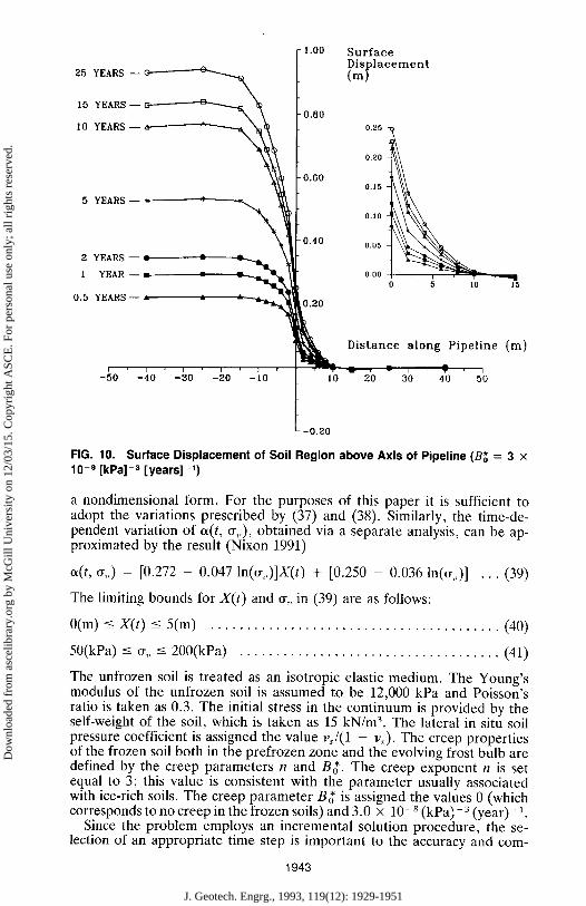
FIG. 10. Surface Displacement of Soil Region above Axis of Pipeline (Bg = 3 x 10⁻⁸ [kPa]-3 [years] -1)
a nondimensional form. For the purposes of this paper it is sufficient to adopt the variations prescribed by (37) and (38). Similarly, the time-de- pendent variation of cfft, ~,) , obtained via a separate analysis, can be ap- proximated by the result (Nixon 1991)
cfft, ~r~,) = [0.272 - 0.047 ln(~,)]X(t) + [0.250 - 0.036 ln(~,)] . . . (39)
The limiting bounds for X ( t ) and ~, in (39) are as follows:
0(m) ~< X ( t ) <- 5(m) . . . . . . . . . . . . . . . . . . . . . . . . . . . . . . . . . . . . . . . . (40)
50(kPa) -< or, _< 200(kPa) . . . . . . . . . . . . . . . . . . . . . . . . . . . . . . . . . . . . (41)
The unfrozen soil is treated as an isotropic elastic medium. The Young's modulus of the unfrozen soil is assumed to be 12,000 kPa and Poisson's ratio is taken as 0.3. The initial stress in the continuum is provided by the self-weight of the soil, which is taken as 15 kN/m 3. The lateral in situ soil pressure coefficient is assigned the value v,/(1 - Vs). The creep properties of the frozen soil both in the prefrozen zone and the evolving frost bulb are defined by the creep parameters n and B~'. The creep exponent n is set equal to 3; this value is consistent with the parameter usually associated with ice-rich soils. The creep parameter B~ is assigned the values 0 (which corresponds to no creep in the frozen soils) and 3.0 x 10⁻⁸ (kPa) -3 (year) -1.
Since the problem employs an incremental solution procedure, the se- lection of an appropriate time step is important to the accuracy and corn-
1943
J. Geotech. Engrg., 1993, 119(12): 1929-1951
Dow
nloa
ded
from
asc
elib
rary
.org
by
McG
ill U
nive
rsity
on
12/0
3/15
. Cop
yrig
ht A
SCE
. For
per
sona
l use
onl
y; a
ll ri
ghts
res
erve
d.
25 YEARS--~~-~ 15 YEARS--~-.,~ 1o VEARS--~---------~"~-, k
- 1 . 0 0
0.80
0.80
5 YEARS~-~'~~ 0.40
2 YEARS -- ~ I YEAR --
b~0
0.5 YEARS!--
Pipeline Displacement (m)
0,30
0.25
0.20
0.15
0,10
0.05
0.00 5
Distance along Pipeline (m)
- 5 0 - 4 0 - 3 0 - 2 0 - 1 0 [ I0 - 20 30 40 50
- 0 . 2 0
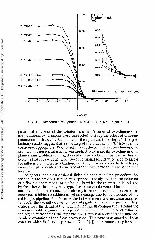
FIG. 11, Deflections of Pipeline (B; = 3 x 10 -8 [kPa] -s [years] -1)
putational efficiency of the solution scheme. A series of two-dimensional computational experiments were conducted to study the effect of different parameters such as B;~, E,, and ~ on the optimum time step dt. The pre- liminary results suggest that a time step of the order of (0.4/B~E)~) can be considered appropriate. Prior to solution of the complete three-dimensional problem, the numerical scheme was applied to examine the two-dimensional plane strain problem of a rigid circular pipe section embedded within an evolving frost heave zone. The two-dimensional results were used to assess the influence of mesh discretizations and time increments on the frost heave induced displacements at the surface of the frost heave zone and at the pipe location.
The general three-dimensional finite element modeling procedure de- scribed in the previous section was applied to study the flexural behavior of a flexible beam model of a pipeline in which the interaction is induced by frost heave in a silty clay type frost susceptible zone. The pipeline is anchored in bonded contact at an already frozen soil region that experiences creep but exhibits no additional volume change due to the presence of the chilled gas pipeline. Fig. 6 shows the finite element discretization adopted to model the overall domain of the soil-pipeline interaction problem. Fig. 6 also shows the detail of the finite element mesh configuration around the frost-susceptible region of the pipeline. The finite element discretization in the region surrounding the pipeline takes into consideration the time-de- pendent evolution of the frost heave zone. This zone is assumed to be of constant width B(t) and depth (d + D + X[t]). The connectivity between
1944
J. Geotech. Engrg., 1993, 119(12): 1929-1951
Dow
nloa
ded
from
asc
elib
rary
.org
by
McG
ill U
nive
rsity
on
12/0
3/15
. Cop
yrig
ht A
SCE
. For
per
sona
l use
onl
y; a
ll ri
ghts
res
erve
d.
25 YEARS 0 15 YEARS [] I0 YEARS
5 YEARS 2 YEARS l YEAR :
0,5 YEARS A
1.20
1.00
0.80
0.60
0.40
0.20
Mm,x Mp
Distance along Pipeline (m)
- 4 0 -30 - 2 0 - 1 0 II~ 1 0 ~ 2 0 30 40
-~176 t -0.80
-0,80 1
-1.00
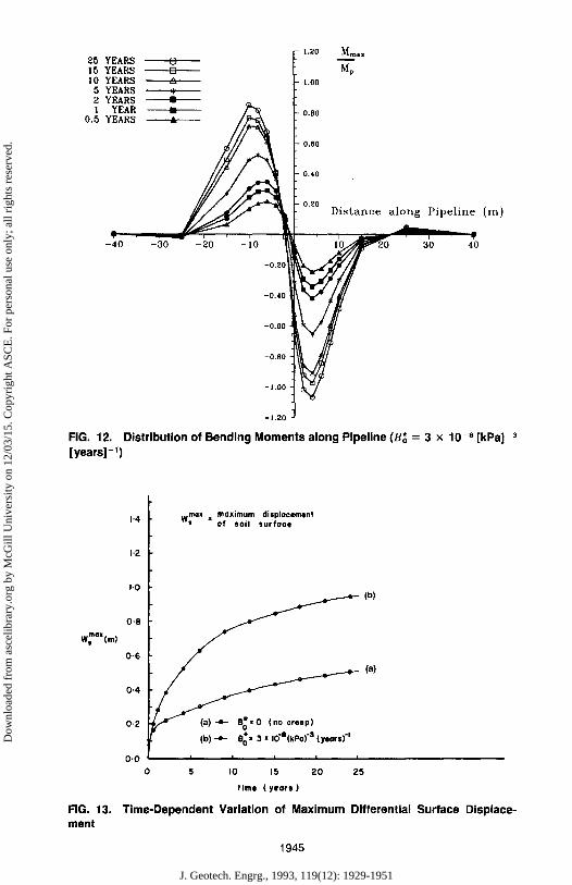
-1.20 FIG. 12. Distribution of Bending Moments along Pipeline (B~ = 3 x 10 -8 [kPa] -a [years] -1)
WmaX(m )
FIG. 13. ment
wmaXl maximum d isp lacement 1.4 = of soil surface
1'2
bO
0'8 ~ (b)
0-6
0'4 ~ (a)
0.2 * 3 x iO' l l (kPa) "8 ( y a o r e ) "1 (b) -e- B 0 �9
0'0 ~ i = = i
5 I0 15 20 25 t i m e ( y e a r s )
Time-Dependent Variation of Maximum Differential Surface Displace-
1945
J. Geotech. Engrg., 1993, 119(12): 1929-1951
Dow
nloa
ded
from
asc
elib
rary
.org
by
McG
ill U
nive
rsity
on
12/0
3/15
. Cop
yrig
ht A
SCE
. For
per
sona
l use
onl
y; a
ll ri
ghts
res
erve
d.
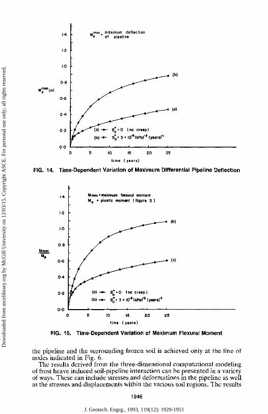
w~ aM (m)
FIG. 14.
max maximum deflection 1.4 Wp = of pipeline
1.2
1,0
0.8 ~ (b)
0.6
(a) 0.4
0.2 ~e" (b)'4- B*o=SX 104(kPo) "3 (yeors) "l
0'0 I I I I I
5 I0 15 20 25
time (years)
Time-Dependent Variation of Maximum Differential Pipeline Deflection
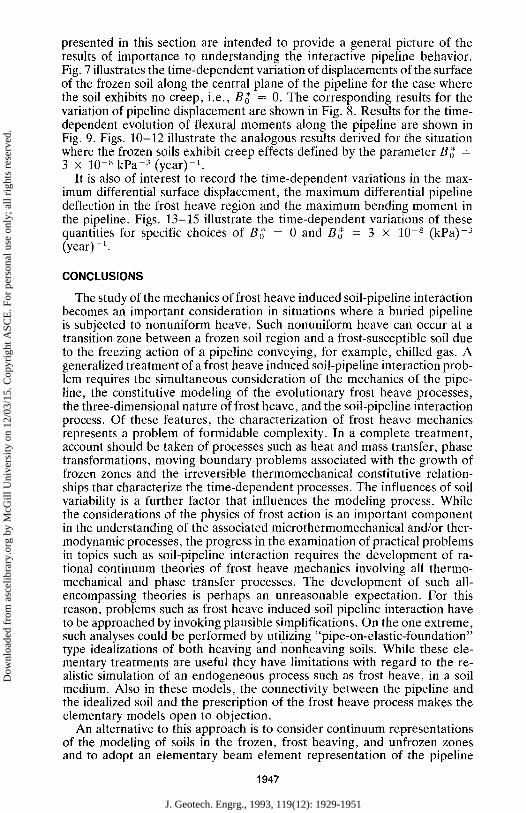
MnKix M p
I-4
1'2
I-0
0.8
0'6
0.4
0.2
0'0
FIG. 15.
Mmex.maximum flexural moment M p I plolfio moment (figure 5 )
(b)
~ ~ (a)
(b) --4- B o �9 3 x I0 "O (kPa) "$ (yeors] -I
I i i i i
5 IO 15 2 0 Z 5
time (years)
Time-Dependent Variation of Maximum FIexural Moment
the pipeline and the surrounding frozen soil is achieved only at the line of nodes indicated in Fig. 6.
The results derived from the three-dimensional computational modeling of frost heave induced soil-pipeline interaction can be presented in a variety of ways. These can include stresses and deformations in the pipeline as well as the stresses and displacements within the various soil regions. The results
1946
J. Geotech. Engrg., 1993, 119(12): 1929-1951
Dow
nloa
ded
from
asc
elib
rary
.org
by
McG
ill U
nive
rsity
on
12/0
3/15
. Cop
yrig
ht A
SCE
. For
per
sona
l use
onl
y; a
ll ri
ghts
res
erve
d.
presented in this section are intended to provide a general picture of the results of importance to understanding the interactive pipeline behavior. Fig. 7 illustrates the time-dependent variation of displacements of the surface of the frozen soil along the central plane of the pipeline for the case where the soil exhibits no creep, i.e., B~' = 0. The corresponding results for the variation of pipeline displacement are shown in Fig. 8. Results for the time- dependent evolution of flexural moments along the pipeline are shown in Fig. 9. Figs. 10-12 illustrate the analogous results derived for the situation where the frozen soils exhibit creep effects defined by the parameter B~ = 3 x 10 8 kPa-3 (year)-1.
It is also of interest to record the time-dependent variations in the max- imum differential surface displacement, the maximum differential pipeline deflection in the frost heave region and the maximum bending moment in the pipeline. Figs. 13-15 illustrate the time-dependent variations of these quantities for specific choices of Bg = 0 and B~ = 3 • 10 -8 (kPa) -3 (year)- i.
CONCLUSIONS
The study of the mechanics of frost heave induced soil-pipeline interaction becomes an important consideration in situations where a buried pipeline is subjected to nonuniform heave. Such nonuniform heave can occur at a transition zone between a frozen soil region and a frost-susceptible soil due to the freezing action of a pipeline conveying, for example, chilled gas. A generalized treatment of a frost heave induced soil-pipeline interaction prob- lem requires the simultaneous consideration of the mechanics of the pipe- line, the constitutive modeling of the evolutionary frost heave processes, the three-dimensional nature of frost heave, and the soil-pipeline interaction process. Of these features, the characterization of frost heave mechanics represents a problem of formidable complexity. In a complete treatment, account should be taken of processes such as heat and mass transfer, phase transformations, moving boundary problems associated with the growth of frozen zones and the irreversible thermomechanical constitutive relation- ships that characterize the time-dependent processes. The influences of soil variability is a further factor that influences the modeling process. While the considerations of the physics of frost action is an important component in the understanding of the associated microthermomechanical and/or ther- modynamic processes, the progress in the examination of practical problems in topics such as soil-pipeline interaction requires the development of ra- tional continuum theories of frost heave mechanics involving all thermo- mechanical and phase transfer processes. The development of such all- encompassing theories is perhaps an unreasonable expectation. For this reason, problems such as frost heave induced soil pipeline interaction have to be approached by invoking plausible simplifications. On the one extreme, such analyses could be performed by utilizing "pipe-on-elastic-foundation" type idealizations of both heaving and nonheaving soils. While these ele- mentary treatments are useful they have limitations with regard to the re- alistic simulation of an endogeneous process such as frost heave, in a soil medium. Also in these models, the connectivity between the pipeline and the idealized soil and the prescription of the frost heave process makes the elementary models open to objection.
An alternative to this approach is to consider continuum representations of the modeling of soils in the frozen, frost heaving, and unfrozen zones and to adopt an elementary beam element representation of the pipeline
1947
J. Geotech. Engrg., 1993, 119(12): 1929-1951
Dow
nloa
ded
from
asc
elib
rary
.org
by
McG
ill U
nive
rsity
on
12/0
3/15
. Cop
yrig
ht A
SCE
. For
per
sona
l use
onl
y; a
ll ri
ghts
res
erve
d.
with a restricted connectivity. An idealization of this type becomes a tenable alternative in instances where the growth of the frozen region can be de- termined via a separate analysis. This is in effect a decoupling of the frost heave process from the soil-pipeline interaction process, which, for the purposes of the determination of the frost zone growth around the pipeline is regarded as a satisfactory simplification. This paper presents such a treat- ment of a soil-pipeline interaction problem where: (1) The generation of frost heave in a frost-susceptible zone is determined via a simplified two- dimensional analysis; (2) the modeling of the soil-pipeline interaction takes into account the elastic and creep responses of the frozen and unfrozen soils; and (3) the three-dimensional geometry of a soil-pipeline interaction problem. With these assumptions, the mechanics of soil-pipeline interaction is induced by the stress dependent volume expansion of the soil during the growth of the heave zone. Within the limitations of this scheme the frost heave induced soil-pipeline interaction can be examined to generate results of interest and benefit to pipeline engineering. The numerical results for the time-dependent evolution of pipeline displacements, surface heave im- mediately above the pipeline, and bending moment distributions along the pipeline indicate trends that have been observed in large-scale controlled laboratory simulations of long-term soil-pipeline interaction during discon- tinuous frost heave.
The a priori prescription of the extent and growth rate of the frost heave region by appeal to a separate two-dimensional analysis is perhaps a re- striction in the current study. This, however, need not be construed as a limitation of the scope of the computational methodology. A satisfactory three-dimensional continuum model of frost heave and frost zone generation can be incorporated within the scope of a three-dimensional analysis to fully integrate the frost heave influences together with the soil-pipeline interac- tion problem. Such all encompassing three-dimensional models of frost heave and frost zone generation along with the study of time-dependent processes in soil-pipeline interaction is expected to be unduly extensive in terms of computer usage.
The primary objective of this study was to ascertain the basic influences of three-dimensional considerations and time-dependent phenomena on the modeling of frost heave induced soil-pipeline interaction. To this extent the analysis has shown that viable computational models of the interactive pro- cesses can be developed and although these models are computing-intensive, useful results of engineering interest can be derived using the continuum approach. The results presented in this paper are intended to give a general perspective of the scope of applicability of the computational modeling. Owing to the choice of a specific pipeline configuration, prescribed frost heave zone generation, and the specific choices of constitutive parameters, it is unrealistic to provide any generalized conclusions. It is, however, clear that creep deformations of the frozen soils have a significant influence on the flexural interaction between the pipeline and the frozen soil. The presence of creep enhances the pipeline displacements in the frost heave zone. These movements in turn contribute to increased flexural moments in the embedded pipeline. This is an important observation that is at variance with conventional interpretations of engineering problems where creep pro- cesses can have the general effect of relieving the stresses in embedded structural elements.
The computational modeling presented here is an essential prelude to assessing the relative importance of the influence of frost heave generation
1948
J. Geotech. Engrg., 1993, 119(12): 1929-1951
Dow
nloa
ded
from
asc
elib
rary
.org
by
McG
ill U
nive
rsity
on
12/0
3/15
. Cop
yrig
ht A
SCE
. For
per
sona
l use
onl
y; a
ll ri
ghts
res
erve
d.
and creep effects in the interaction between a buried pipeline and a soil region experiencing discontinuous frost heave. The results of the study are sufficiently encouraging to warrant the incorporation of a plausible frost heave model within the computational scheme. Such a model should address features such as the influence of large strains in the frost heave zones, limiting strength characteristics of interfaces, three-dimensional shell-type geometry of the buried pipeline, and creep rupture damage and failure in the frozen soil regions, These topics will be addressed in future investiga- tions.
ACKNOWLEDGMENTS
The work described in this paper was initiated through a research agree- ment between Selvadurai and Associates Inc., Materials and Mechanics Research Consultants, Ottawa, Ontario, Canada and the Centre for Frontier Engineering and Research, Edmonton, Alberta, Canada. The writers grate- fully acknowledge the contributions of Dr. J. F. Nixon, Esso Resources Canada Ltd., Calgary, Alberta, Canada, who provided the computational results pertaining to the 2D Geothermal Simulator Analysis (available through Mitre Software, Edmonton, Alberta, Canada) and made many helpful com- ments. The writers are grateful to Dr. M. C. Au for assistance with the computations. The writers gratefully acknowledge the positive comments and encouragements of the reviewers.
APPENDIX. REFERENCES
Andersland, O. B., and Anderson, D. M., eds. (1978). Geotechnical engineering for cold regions, McGraw-Hill, New York, N.Y.
Anderson, D. M., Williams, P. J., Guymon, G. L., and Kane, D. L. (1984). "Prin- ciples of soil freezing and frost heaving." Tech. Council on cold regions engineering monograph, Frost action and its control, ASCE, New York, N.Y., 1-21.
Ariman, T., Liu, S. C., and Nickell, R. E. (1979). Lifeline earthquake engineering-- buried pipelines, PVP 34, Amer. Society of Mech. Engrs., New York, N.Y.
Bahmanyar, G. H., and Harrison, P. J. (1985). "Pipelines surcharged by seasonally frozen soils." Ground Freezing, Proc. 4th Int. Symp. on Ground Freezing, S. Kinoshita and M. Fukuda, eds., A. A. Balkema, Rotterdam, The Netherlands, 291-296.
Dallimore, S. R., and Williams, P. J., eds. (1984). Pipelines and frost heave: a seminar. Carleton University, Ottawa, Canada, 1-75.
Ice segregation and frost heaving. (1984). National Academy Press, Washington, D.C. Jeyapalan, J. K., ed. (1985). Advances in underground pipeline engineering pro-
ceedings of the international conference, Madison, Wisc., ASCE Publications, N.Y. Konrad, J.-M., and Morgenstern, N. (1984). "Frost heave prediction of chilled
pipelines buried in unfrozen soils." Can. Geotech. J., 21, 100-115. Ladanyi, B. (1972). "An engineering theory of creep of frozen soil." Can. Geotech.
J., 9, 63-80. Ladanyi, B. (1981). "Mechanical behaviour of frozen soils." Proc. Int. Syrup. Mech.
Behavior of Structured Media: Studies in Appl. Mech., A. P. S. Selvadurai, ed., Vol. 5B, 205-245.
Ladanyi, B., and Lemaire, G. (1984). "Behaviour of a buried pipeline under dif- ferential frost heave conditions." Proc. CSCE Cold Regions Engineering Specialty Conference, Montreal, Quebec, 161-176.
Ladanyi, B., and Shen, M. (1989). "Mechanics of freezing and thawing in soils." Frost in geotechnical engineering, int. syrup., Saariselka, Finland, H. Rathmayer, ed., Tech. Res. Centre of Finland, Espoo, 73-103.
1949
J. Geotech. Engrg., 1993, 119(12): 1929-1951
Dow
nloa
ded
from
asc
elib
rary
.org
by
McG
ill U
nive
rsity
on
12/0
3/15
. Cop
yrig
ht A
SCE
. For
per
sona
l use
onl
y; a
ll ri
ghts
res
erve
d.
"List of source and reference material on pipeline design." (1980). ASCE Task Committee Report.
Morgenstern, N. (1981). "Geotechnical engineering and frontier resource develop- ment." Geotechnique, 31,305-365.
Myrick, J. E., Isaacs, R. M., Liu, C. Y., and Luce, R. G. (1982). "Frost heave program of the Alaskan natural gas transportation system." Amer. Soc. Mech. Engrs. Tech. Paper, 82/WA/HT-12, 1-8.
Nixon, J. F. (1987a). "Pipeline frost heave predictions using the segregation potential frost heave method." Proc. Offshore Mechanics and Artic Engineering ( OMAE), Conf., Houston, Tex., 1-6.
Nixon, J. F. (1987b). "Thermally induced heave beneath chilled pipelines in frozen ground." Can. Geotech. J., 24, 260-266.
Nixon, J. F., Morgenstern, N. R., and Reesor, S. N. (1983). "Frost heave-pipeline interaction using continuum mechanics." Can. Geotech. J., 20, 251-261.
Parameswaran, V. R. (1987). "Extended failure time in the creep of frozen soils." Mech. Mater., 6, 233-243.
Parmuzin, S. Yu, Perelimiter, A. D., and Naidenok, I. Y. (1988). "Studies of pipeline interaction with heaving soils." Proc. Fifth Int. Conf. Permafrost, Trondheim, Norway, 1307-1311.
Phukan, A. (1985). Frozen ground engineering. Prentice Hall Inc., Englewood Cliffs, N.J.
Pickell, M. B., ed. (1983). Pipelines in adverse environments II, proceedings of the ASCE specialty conference. San Diego, Calif., ASCE, New York, N.Y.
Selvadurai, A. P. S. (1983). "A soil-structure interaction problem for a group of connected flexible pipelines." Pipelines in adverse environments, ASCE specialty conf., M. B. Pickell, ed., San Diego, Calif., 199-211.
Selvadurai, A. P. S. (1985). "Soil-pipeline interaction during ground movement." ARCTIC '85, civil engineering in the arctic offshore ASCE specialty conf., F. L. Bennett and J. L. Machemehl, eds., San Francisco, Calif., 763-767.
Selvadurai, A. P. S. (1988). "Mechanics of soil-pipeline interaction." Proc. CSCE Annual Conf., Calgary, Alta, Vol. 3,320-334.
Selvadurai, A. P. S. (1991). "Mechanics of buried pipelines induced by random ground movement." Proc. CSCE Annual Conf. Engrg. Mech. Symp., Vancouver, British Columbia, Canada, 142-151.
Selvadurai, A. P. S., Au, M. C., and Shinde, S. B. (1990). "Soil-pipeline interaction in a pipeline with prescribed displacements." Proc. 1st Nat. Conf. on Flexible Pipes, Columbus, Ohio, S. M. Sargand, G. F. Mitchell, and J. O. Hurd, eds., A. A. Balkema, Rotterdam, The Netherlands, 135-142.
Selvadurai, A. P. S., and Lee, J. J. (1981). "Soil resistance models for the stress analysis of buried fuel pipelines." Interim Report, Tech. Res. and Development Project, Res. and Engrg., Bechtel Group Inc., San Francisco, Calif.
Selvadurai, A. P. S., and Lee, J. J. (1982). "Soil resistance models for the stress analysis of buried fuel pipelines." Final Report, Tech. Res. and Development Proj- ect, Res. and Engrg., Bechtel Group Inc., San Francisco, Calif.
Selvadurai, A. P. S., Lee, J. J., Todeschini, R. A. A., and Somes, N. F. (1983). "Lateral resistance in soil-pipeline interaction." Pipelines in Adverse Environments H, San Diego, Calif., M. B. Pickell, ed., ASCE, New York, N.Y., 259-283.
Selvadurai, A. P. S., and Pang, S. (1988). "Non-linear effects in soil-pipeline inter- action in a ground subsidence zone." Proc. 6th Int. Conf. Num. Meth. Geomech., Innsbruck, Austria, G. Swoboda, ed., Vol. 2, 1085-1094.
Shen, M., and Ladanyi, B. (1991). "Soil-pipe interaction during frost heaving around a buried chilled pipeline." Cold Regions Engineering, Proc. 6th Int. Specialty Conf., Hanover, N.H., D. S. Sodhi, ed., ASCE, New York, N.Y., 11-21.
Shibata, H., Katayama, H., and Ariman, T., eds. (1980). Recent advances in lifeline earthquake engineering in Japan, PVP 43, Amer. Society of Mech. Engrs.
Slusarchuk, W. A., Clark, J. I., Nixon, J. F., Morgenstern, N. R., and Gaskin,
1950
J. Geotech. Engrg., 1993, 119(12): 1929-1951
Dow
nloa
ded
from
asc
elib
rary
.org
by
McG
ill U
nive
rsity
on
12/0
3/15
. Cop
yrig
ht A
SCE
. For
per
sona
l use
onl
y; a
ll ri
ghts
res
erve
d.
P. N. (1978). "Field test results of a chilled pipeline buried in unfrozen ground." Proc. 3rd Int. Permafrost Conf., Edmonton, 1,878-883.
Smith, D. J., ed. (1981). "Lifeline earthquake engineering: current state of knowl- edge." Proc. 2nd ASCE Specialty Conf. of Tech. Council on Lifeline Earthquake Eng., Oakland, Calif.
Svec, O. J. (1989). "A new concept of frost-heave characteristics of soils." Cold Reg. Sci. Technol., 16, 271-279.
Tsytovich, N. A. (1975). The mechanics of frozen soil. McGraw-Hill, New York, N.Y.
Zienkiewicz, O. C. (1971). The finite element method in engineering science. McGraw- Hill, New York, N.Y.
1951
J. Geotech. Engrg., 1993, 119(12): 1929-1951
Dow
nloa
ded
from
asc
elib
rary
.org
by
McG
ill U
nive
rsity
on
12/0
3/15
. Cop
yrig
ht A
SCE
. For
per
sona
l use
onl
y; a
ll ri
ghts
res
erve
d.