Embed Size (px)
Citation preview
.r. -_·--
•
.-_ • .!
·~·.-:..
. -' --~ -
..... .:.:;._-·-
·...... - .. ;.o:-.-. -·
Plastic Design of.Unbraced Frames
PLASTIC DESIGN OF UNBRACED MULTISTORY SPACE FRAMES
by
Reinhard L. Gsellmeier
A Thesis Presented to the Graduate Committee
of Lehigh University in Candidacy for the Degree of
Master of Science in
Civil Engineering
FRITZ ENGINEERING lABOR.hvRY LIORARY
Fritz Engineering Laboratory Department of Civil Engineering
Lehigh University Bethlehem, Pennsylvania
April 1975
Fritz Engineering Laboratory Report No. 367.14
ACKNOWLEDGMENTS
The author wishes to express his sincere appreciation to
Professor George C. Driscoll, Jr., Assistant Director of Fritz Engi
neering Laboratory, who supervised this thesis. Without his techni
cal guidance and encouragement this thesis would not be possible.
The research for this thesis was conducted at Fritz Engi
neering Laboratory, Lehigh University, Bethlehem, Pennsylvania, and
was carried out as part of an investigation s~onsored jointly by the
American Iron and Steel Institute, National Science Foundation, and
Joint Committee for the Planning and Design of Tall Buildings.
Professor D. A. VanHorn is the Chairman of the Civil Engineering
Department and Professor L. S. Beedle is Director of Fritz Engineer
ing Laboratory.
Special thanks are also extended to Professor Lynn S.
Beedle, who as Chairman of the Joint Committee for the Planning and
Design of Tall Buildings, provided his assistance to the author.
The patience and encouragement of the author's wife were
also vital to the completion of this thesis. The manuscript was
typed by Joan Gorski, Debbie Zappasodi and Sheila Novak.
iii
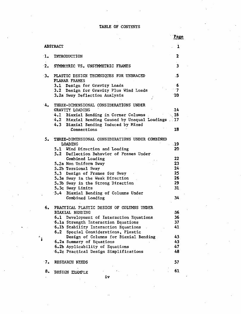
TABLE OF CONTENTS
··page
ABSTRACT 1
1. INTRODUCTION 2
2. SYMMETRIC VS. UNSYMMETRIC FRAMES 3
· 3. PLASTIC DESIGN TECHNIQUES FOR UNBRACED PLANAR FRAMES 3.1 Design for Gravity Loads 3.2 Design for Gravity Plus Wind Loads 3.2a Sway Deflection Analysis
6 .7 10
· 4. THREE-DIMENSIONAL CONSIDERATIONS UNDER GRAVITY LOADING 14 4.1 Biaxial Bending in Corner Columns ,16 4.2 Biaxial Bending Caused by Unequal Loadings .. 17 4.3 Biaxial Bending Induced by Mixed
Connections 18
· 5. THREE-DIMENSIONAL CONSIDERATIONS UNDER COMBINED
6.
LOADING . .19 5.1 Wind Direction and Loading 20 5.2 Deflection Behavior of Frames Under
Combined Loading 22 5.2a Non Uniform Sway 23 5.2b Torsional Sway 24 5.3 Design of Frames for Sway 25 5.3a Sway in the Weak Direction 26 5.3b Sway in the Strong Direction 29 5.3c Sway Limits 31 5.4 Biaxial Bending of Columns Under
Combined Loading 34
PRACTICAL PLASTIC DESIGN OF COLUMNS UNDER BIAXIAL BENDING 6.1 Development of Interaction Equations 6.1a Strength Interaction Equations 6.lb Stability Interaction Equations 6.2 Special Considerations, Plastic
Design of Columns for Biaxial Bending 6.2a Summary of Equations 6.2b Applicability of Equations 6o2c Practical Design Simplifications
36 36 37 41
43 43 47 48
· 7. RESEARCH NEEDS
8 • PESIGN EXAMPLE
57
61 iv
TABLE OF CONTENTS (continued)
:9. FIGURES
10. APPENDIX I - DESIGN AIDS DA-I - Properties of Beam Columns DA-II - Strength Interaction Curves DA-III- Stability Interaction Curves
11. APPENDIX II - COLUMN. DESIGN EXAMPLES
12. REFERENCES
13. VITA
80
110 111 113 114
122
131 135
. ·ABSTRACT
A review is made of the plastic design method fo.r
unbraced planar frames. Designing for gravity and combined loads
is shown. A discussion of drift analysis using the subassemblage
method is given.
An examination of some of the three-dimensional effects
which can occur in symmetric unbraced multistory space frames is
made. The consideration of these effects in a practical manner
for design is discussed. Some three-dimensional effects under
both gravity and combined loading are illustrated.
The practical plastic design of columns in biaxial
bending, a necessary tool when considering these effects, is
shown. Practical design charts for strength and stability, based
on! recent interaction equations for biaxial bending, are developed .• 'i ...
Several. design examples are included which illustrate the plastic
design technique and the practical design of columns in biaxial
bending.
1
1. INTRODUCTION
All building frames are space frames. It is usual design
practice to model symmetric building frames as a series of two-
dimensional, planar frames. For the majority of the structural ele-
ments within a building, this design approximation will give reason-
able member sizes. However, certain components of the building design
may require the consideration of three-dimensional effects.
The purpose of this thesis will be to comment on certain
three-dimensional effects in symmetric building frames, and how they
may be approximated in a practical design approach. Although s~
metric frames are not usually considered as space frames, the consid-
eration of symmetric frames is a first step in the practical plastic
design of space frames.
A review will first be made of the plastic design techniques
of unbraced planar frames, then three-dimensional considerations under
.gravity loading and combined loading will be considered. The practi-
cal plastic design of columns under biaxial bending, a basic tool
when considering three-dimensional action, is shown. Design aids and
design examples for biaxial bending design are included. This thesis
concludes with a design example which illustrates some of the three-.. .. dimensional plastic design techniques.
2
2. SYMMETRIC VS. UNSYMMETRIC FRAMES
With respect to its floor framing pattern, a building
frame may be classified into one of two categories:
1. Frames which are locally symmetric with respect to a bay
(two columns spanned by a girder) or a bent (series of adjacent bays)~
The floor framing plan of Turtle Creek Village Offices in Dallas,
Texas, shown in Fig. 2.1, illustrates a symmetric frame.
2 •. Frames which are locally unsymmetric with respect to a
bay or a bent. The floor framing plan of One Chemung Canal Plaza
Offices in Elmira, New York, shown in Fig. 2.2, illustrates an un-
symmetric frame. •
All building frameworks, whether they are symmetric or un
symmetric, will act to resist the loads as a three-dimensional space
frame. This is true for both gravity or gravity plus wind loads.
The methods of designing symmetric versus unsymm~tric frames are
. quite different, however.
Due to their geometry, unsymmetric frames inherently in
volve a three-dimensional design-procedure. Members must be designed
to resist torsional stresses, as well as biaxial bending. Addition-
~J ally, the critical externally applied loading patterns which will
produce maximum stresses in each of the members are not always ob
vious. A rigorous series of loading patterns may have to be investi
gated.
3
" ~t
~ ~
~
~ .. Symmetric frames, on. the other hand, are often approximated
as a series of planar frames with in-plane loadings. For most por-
tions of the building design, it has been shown that this is a reason-
able and accurate approxilllation. In certain instances, however,
three-dimensional effects, especially in considering biaxial bending
of .c;:olumns in urtbraced building frames, should be investigated by the
designer.
This thesis will limit its discussion to symmetric building
frames.
4
3. PLASTIC DESIGN TECHNIQUES FOR UNBRACED PLANAR FRAMES
· A brief review of the plastic design technique as applied
to unbraced multistory frames will be made here only to serve as a
reference for later chapters in this thesis. For further informa
tion, refer to Refs. 1 to 6.
In the plastic design.of any building frame, there are
three criteria which the frame must meet to satisfy structural as
well as human response requirements:
1) The frame must have sufficient strength to carry full
factored gravity loads alone (F = 1.7).
2) The frame must have sufficient strength to carr:y
factored gravity plus wind loads (F = 1.3). This condition is re
ferred to as the combined loading case.
3) The frame must be sufficiently stiff when subjected to
combined loads such that the horizontal drift at.working loads is
.within acceptable limits. These drift limits may be imposed either
to prevent damage to non-structural components such as walls and
windows, or to prevent occupant discomfort.
In the articles below, the design techniques used to satisfy
~.each of the above three requirements will be briefly discussed, as
applied to plastically designed unbraced multistory frames.
5
3.1 Design for Gravity Loads
The first step is to make an estimate of the gravity loads,
which include both dead and live loads. Based on their tributary
areas, the axial loads in the columns can then be calculated. In
this step, live load reduction factors should be used in calculating
the column axial loads.
Next, girder fixed end moments are calculated, assuming a
uniformly distributed factored gravity loading, as illustrated in
Fig. 3 .1. No live load reduction factors should be used here .•
Notice in Fig. 3.1 the formation of a three-hinged mechanism in the
girders, with moments occurring at the ends of the girders first. It
is recommended in unbraced frames that moment resistant connections
be used at both ends of the girders in wind resistant bents. The
reason is that a girder with one end hinged will allow excessive
deflections under combined loading, unless the girder size is made
extremely large. For supported bents which are assumed to carry no
wind, however, it may be structurally and economically feasible to
have one or both ends of the girder pinned. Girders can then be
selected for the roof and all the floors based on the required M • . p
It should be noted that all the floor girders in a given bay will
··usually be subjected to the same gravity loading, and therefore will
all be the same size to satisfy this loading requirement.
The column moments due to gravity loading are calculated by
assuming that the net joint moments from the girder fixed end moments
and eccentric girder end shears are distributed equally to the columns 6
above and below the joint. Fig~ 3.2 illustrates the effect of the
girder shear eccentricity. Fig. 3.3 illustrates the assumed distri-
bution of loads to the columns. By assuming that the joint moment
is distributed equally to the columns above and below the joint, we
are assuming that the columns above and below the joint have approx-
imately the same stiffness. In an actual high-rise building frame,
this condition is very closely approximated, as column sizes vary
only slightly from story to story. In any event, a~slll~P:;ng ail.
equal distribution is conservative, since it is a lower-bound, equil-
ibrium approach.
In Fig. 3.3, notice that the columns will be subjected to
reverse curvature. If the girder loads are equal, the columns will
in fact be bent in symmetric reverse curvature. This is the usual
case for gravity loads.
Once the column axial loads and end moments have been de-
termined, the columns may be designed, using be~column interaction
equations or curves. The columns must be designed to satisfy both
in-plane bending strength and lateral torsional buckling stability.
Since the columns are in reverse curvature, usually the in-plane
bending strength criteria will control. A more detailed discussion
iof the column design procedure is given in Chapter 6.
3.2 Design for Gravity Plus Wind Loads
In the design for the combined load case, a smaller load
factor (F = 1.3 vs. F = 1.7 for gravity loads alone) is used. 7
_. -: ... :
This smaller load factor is aliowed because it appears unlikely that
both full factored gravity load and full factored wind.load would
occur simultaneously on the structure. Thus, the first step in this
design procedure is to calculate the factored column and girder grav-
ity loads (this information is usually known from the design of the
bent for full factored gravity loads).
I
The next step is to formulate equilibrium of the frame in
its displaced position. An estimate is made of the lateral wind
pressure. Also needed is an estimate of the ultimate sway drift
index, (~/h)ult" Usually (~/h) 1 is estimated somewhat larger than u t
expected, to give a somewhat conservative design.
Equilibrium of a story within a frame in its displaced
position can now be formulated, as shown in Fig. 3.4. From Fig. 3.4
the sum of the colunm end moments within the story required to resis·t
the overturning wind and gravity load moments is given as
LM = (I:H)h + (D>)~ c (3.1)
where I:H is the sum of the factored wind loads down to the level and
I:P is the sum of the factored gravity loads down·to the level. This
story equilibrium step is done for all the stories within a frame,
usually working from the top down. In this step, the P~/h shears in
i I the supported bents must also be taken into consideration. These P~ h
shears in the supported bents are usually assumed to be transferred
by diaphragm action of the floor slabs to the wind resistant bents.
8
··"~-,r.:.
The sum of column end moments in a story is then distrl-
buted to the individual columns. Any logical, reasonable distrib.u-
tion may be assumed by the designer - for instance, distributing the
sum of the column end moments (l:M ) equally to each of the column c
ends.
The next step is to consider equilibrium of two consecutiv~
stories to determine the effects of the previously determined column
end moments, as shown in Fig. 3.5. The following equilibrium equation
may be derived from the fact that the sum of the moments around each
joint must equal zero:
l:M = 1/2 [ (l:M ) 1 + (l:M ) J g c n- c n (3.-2}
where rM equals the sum of the girder joint moments for a level. ·g
The sum of girder joint moments for each bay is then calculated by
distributing to each girder a percentage of the total level girder
joint moments, l:M • Although this distribution is arbitrary, an g
equal distribution usually results in more nearly equal girder sizes
"for all girders on a level.
The girders may then be designed to resist these moments
plus the moments caused by the factored gravity loads acting on the
girders themselves. Fig. 3.6 shows a typical bending moment diagram
ifor a girder with wind from the left. MI and M2
represent the girder
end moments. Notice that girder moments are calculated for center-to-
center spans, but all plastic behavior is assumed to occur within the
9
girder clear spans since the joints within the boundaries of the column
are assumed relatively rigid. The statical solution of the girder in
Fig. 3.6 will give values of the required girder ~· In Fig. "3.6 a
mechanism forms. Often for slender frames in which sway may be a
problem, the maximum girder positive plastic moment is restricted to
a value less than Mp.
The final step, called moment balancing, is to bring column
moments into balance with girder moments. The girder end moments and
shears of Fig. 3.6 are transferred to the column center-lines. The
column joint moments are then adjusted so that they are in equilibrium
with the girder end moments.
These column joint moments, together with column thrusts
adjusted for the girder shears, form the basis of design for the
columns under the combined loading case.
Obviously, the larger sections, whether governed by the
·gravity or combined loading case, control the design. For most
frames, member sizes will be governed by gravity loads in the upper
stories and by combined loads in the middle and lower stories.
. 3.2a Sway Deflection Analysis -~
In the preliminary design of an unbraced frame, a censer-
vative estimate of the story drift at ultimate load is made. The
preliminary member sizes _should_ then be analyzed for drift at both
10
working and ultimate loads. The values of calculated drift shoUld
then be compared to some acceptable drift limits.
There are many methods available for calculating drift de
flections in a building. These may range from rigorous second-order.,
elastic-plastic stiffness formulations for an entire frame, to simple
one-story models. None of the methods allow for a quick calculation
of the sway deflections, but some methods are simpler than others.
One of the more popular methods is the sway subassemblage method de
veloped at Lehigh University. In this section some of the basic
principles and results of this method will be given. A more detailed
discussion of the sway subassemblage method is given in Refs. 7 to
13.
The sway subassemblage method uses a model called an asse~
blage to represent a story in a building frame. Fig. 3.7 illustrates
a typical story in a frame as represented by an assemblage. The
assemblage will consist of the girders and a portion of the columns
below the floor.level extending down to a row of assumed inflection
points. Furthermore, the assemblage is separated into subas.se~
blages, each subassemblage consisting of one of the columns plus
the girders framing into the column top. Typcial exterior and in-
iterior subassemblages are illustrated in Fig. 3.8.
The shear versus drift relationship for the assemblage is
determined by ~ displacement .method during an assumed set of joint
rotations 0. Changes in the girder end moments during the rotations
11
-
0 can be used to determine other functions such as the column end
moments and the drift ~. The relationship between these functions
is calculated as girder moments change from a state of at-rest
equilibrium under factored gravity loads (F = 1.3) to a final state
of combined gravity and lateral load equilibrium. It may be noted
that gravity loads remain at a constant factored level of F = 1.3 as
the wind loads are increased.
The resulting drift ~ versus horizontal shear rH relation
ship for the story can then be plotted, as shown in Fig. 3.9. From
this plot, it can be determined if the sway at working wind loads is
within acceptable limits (see Art. 5.3C). Also it can be checked if
the story has sufficient strength to reach the factored ultimate
wind load (F = 1.3). If additional strength or stiffness is needed,
it is more effective to increase the girder sizes. Fig. 3.9 shows
the effect of increasing the girders vs. increasing the columns. For
a more detailed explanation see Article 5.3a.
It is not necessary to analyze all the stories in a build
ing for drift. For medium sized frames (about 20 stories), it is
usually sufficient to analyze one story near the top, middle, and
bottom. If each of these stories sways within acceptable limits,
iit can be assumed that all the stories have an acceptable sway.
This is a reasonable assumption, since the stiffness of a multistory
frame changes gradually from one story to the next, and does not make
sudden drastic increases between adjacent stories.
12
When deciding which of several adjacent stories to analyze,
it is usually best to select the most critical story. For instance,
since columns come in two story lengths, the lower of the two floor
levels fastened to the-column is critical, since it carries a larger
wind load.
13
4o THREE-DIMENSIONAL CONSIDERATIONS UNDER GRAVITY LOADING
As discussed in Chapter 3, building frames must be designed
to resist factored gravity loads alone (F = 1.7). Under this type of
loading, three-dimensional resistance of the frame as a whole does
not occur for symmetric frames. Local three-dimensional phenomena
can occur, however, to cause biaxial bending in some of the building
columns under this type of loading.
In this chapter, three cases will be considered which cause
biaxial bending in columns under gravity loading:
1) Biaxial bending in corner columns.
2) Biaxial bending caused by unequal loadings along
exterior girders.
3) Biaxial bending induced by mixed connections.
In order to illustrate these cases, the building frame
shown in Fig. 4.1 will be referred to in this chapter.
In Fig. 4.1 notice that the building has a weak direction
and a strong direction. The weak direction of the building is, for
most frames, the direction with the fewest number of bays. Because
of the fewer number of resistant bays and longer exposed surface area, .;
j. wind blowing in the weak direction is more critical than wind blowing
in the strong direction. For this reason columns are usually oriented
with their strong axis in the weak direction of the building. Addi-
. tionally, floor girders in the weak direction (Fig. 4.1) are usually
14
i
fastened to columns at both ends with moment-resistant connections.
These fixed-fixed floor girders offer a much higher wind resistance
than girders with one end fixed and one end simply connected (see
Art. 5.3a). Girders with both ends simply fastened can offer no wind
resistance.
Spandrel girders (Fig. 4.1) will be referred to here as
girders which run along the exterior of a building. Spandrel girders
usually carry some type of exterior wall loading, but sometimes they
are framed with floor beams to carry part of the floor loading as
well. Spandrel girders are either fastened with rigid connections or
simple connections. In unbraced frames, however, at least some of
the spandrel girders must be rigidly fastened at both ends to help
resist the wind loading in the strong direction.
For the frame shown in Fig. 4.1, notice that there are five
bays in the strong direction. Because of the smaller wind load in
the strong direction, girders are rigidly framed in only the two end
bays. Resistance to the wind loads is not needed in the remaining
bays in the strong direction.
It may be mentioned that if a building frame is more square
in shape, with an approximately equal number of bays in both direc-
tions, then it has no definite strong or weak directions. A building
with this geometry may very likely have all of its girders rigidly
framed.
15
4.1 Biaxial Bending in Corner Columns
Corner columns in locally symmetric building frames will
be framed by two mutually perpendicular spandrel girders. Consider
corner columns Al, A6, Cl and C6 in Fig. 4.lo The spandrel girders
framing.into these columns are fixed at both ends, and hence form a
three-hinged beam mechanism under factored gravity loads as shown in
Fig. 3.1. As shown in Fig. 4.2, the fixed end moments of the span-
drel girders will.produce biaxial bending in these corner columns.
Notice that the fixed-end moments of the spandrel girders are assumed
to be distributed equally to the columns above and below the joint.
This convenient assumption-is acceptable in plastically designed tall
buildings (more than 5 stories), since column stiffnesses generally
change very slightly from one story to the next adjacent story.
Also notice in Fig. 4.2 that if M 1 were equal to M 3
and . p p
Mp2 were equal to Mp4 (this would imply equal gravity loading in the
upper and lower stories, which usually occurs in tall buildings),
then the column would be bent in symmetric reverse curvature in both
directions. For such columns, the governing design crit~ria would
probably be biaxial bending strength.
The corner columns would only be subjected to uniaxial
bending if the spandrel girders framing into them in the strong d·i-
rection were fastened with simple shear connections only. Since
these spandrel girders would then transfer their shear to the webs
of the columns, no moment about the columns weak axis is induced
16
because no eccentricity exists· (in fact, a .small amount of eccentri
city would exist). This shear eccentricity would result in a bending
moment about the column's strong axis. This moment, coupled with
the weak axis moment due to the spandrel girders in the weak direc
tion, would produce biaxial bending. Ordinarily, corner columns will
be oriented so that the spandrel girders in the strong direction
frame into the column's web.
4.2 Biaxial Bending Caused By Unequal Loadings
The girders which span between two adjacent exterior
columns are referred to as·spandrel girders, as shown in Fig. 4.1.
Usua~ly, two adjacent spandrel girders will be carrying the
same load, often this load being an exterior wall load. When these
adjacent girders carry the same load, the column into which they
frame will not be subjected to any net moment about an axis perpen
dicular to the girders.
Sometimes, however, two adjacent spandrel girders will be
carrying two widely different types of loading. Such a situation
could occur, for instance, when the exterior facade is brick in one
bay and say glass in the next bay. Consider Col. Bl and the girders
framing into it as shown in Fig. 4.3. One spandrel carries a load of
w1, the other spandrel carries a load of w2• The resulting fixed end
moments are, respectively, M1
and M2
• As shown, w1
< w2 and hence
17
The net moment on the columns above and below is
• This moment, together with the moment Mp3
/2 carried
over to the column from the interior floor girder, produces biaxial
bending in the column.
It may be pointed out that if the spandrel girders were
both simply fastened to the column flanges, a small bending moment
would be transferred to the columns due to the eccentricity of the
unequal shear forces. If, however, the column were rotated 90° such
that the spandrel girders were simply fastened to the column web,
the unequal shear forces would have no eccentricity. In this case
only uniaxial bending of column Bl would occur.
4.3 Biaxial Bending Induced By Mixed Connections
In Fig. 4.1, consider column C2. About its strong axis,
it is rigidly framed by a floor girder. This girder will produce a
net moment about the columns strong axis. For the spandrel girders,
one is rigidly fastened and one is simply fastened. As a result,
these girders will produce a net moment about the columns weak axis.
As a result, column C2 will also be in biaxial bending.
18
5. THREE-DIMENSIONAL CONSIDERATIONS UNDER COMBINED LOADING
As discussed in Chapter 3, building frames must be designed
to resist factored gravity plus wind loads (F = 1.3). This is called
the combined loading case.
Under thi·s type of loading, all frames, whether they are
symmetric or not, will act as space frameworks to resist the loads.
The building may not sway uniformly, it may sway in two directions
simultaneously, or it may twist. If all of these factors are exactly
considered, however, the design of any frame would be complex indeed.
In this chapter certain design approximations and simplifications
which can be used for regular, symmetric frames will be discussed.
It will be stated here that these approximations are not rigorous
analytically, but they will lead to a practical, reasonable design.·
Some of the techniques have been used in the past for the elastic
design of multistory frames, but their applications to plastic design
have been rather limited.
The following topics will be discussed in this chapter:
(1) Wind direction and loading.
(2) Deflection behavior of frames under wind:
a. Sway approximations
b. Torsional behavior
19
. -
(3_) · ])esign of frames for sway:
<. a. _Sway in the weak direction.
_-'-_b.. Sway in the strong direction.
c. Sway limits.
: (-4} B~al bending of columns under combined loads.
5.1 Wind Direction and Loading
Wind c~ blow in any direction. In addition, it may be
turbulant, non-uni£orm over the face of a building, and it may create
suction forces on the building. Most building codes neglect the non-
uniform, turbulant, suction-action of the wind (although the Hancock
Building in Boston clearly illustrates some of the inaccuracies in-
volved). It is felt that large over-estimating of the wind working
loads will safeguard against ~ny ill effects created by these assump-
tions. However, the problem of designing a building for a certain
critical wind direction is up to the designer.
As an illustration lets consider the symmetric, rectangular
shaped building frame in Fig. S.la. It is subjected to the most
general type of wind loading pattern, wind coming in at an angle to
the building's prinicpal directions. The components of the wind ~
i in the strong and weak directions of the building will be Wsin9
and Wcos0, respectively. Notice that the wind shearing forces
on the building have been set equal to zero. This is not exactly
correct, since the building must have a drag coefficient greater
20
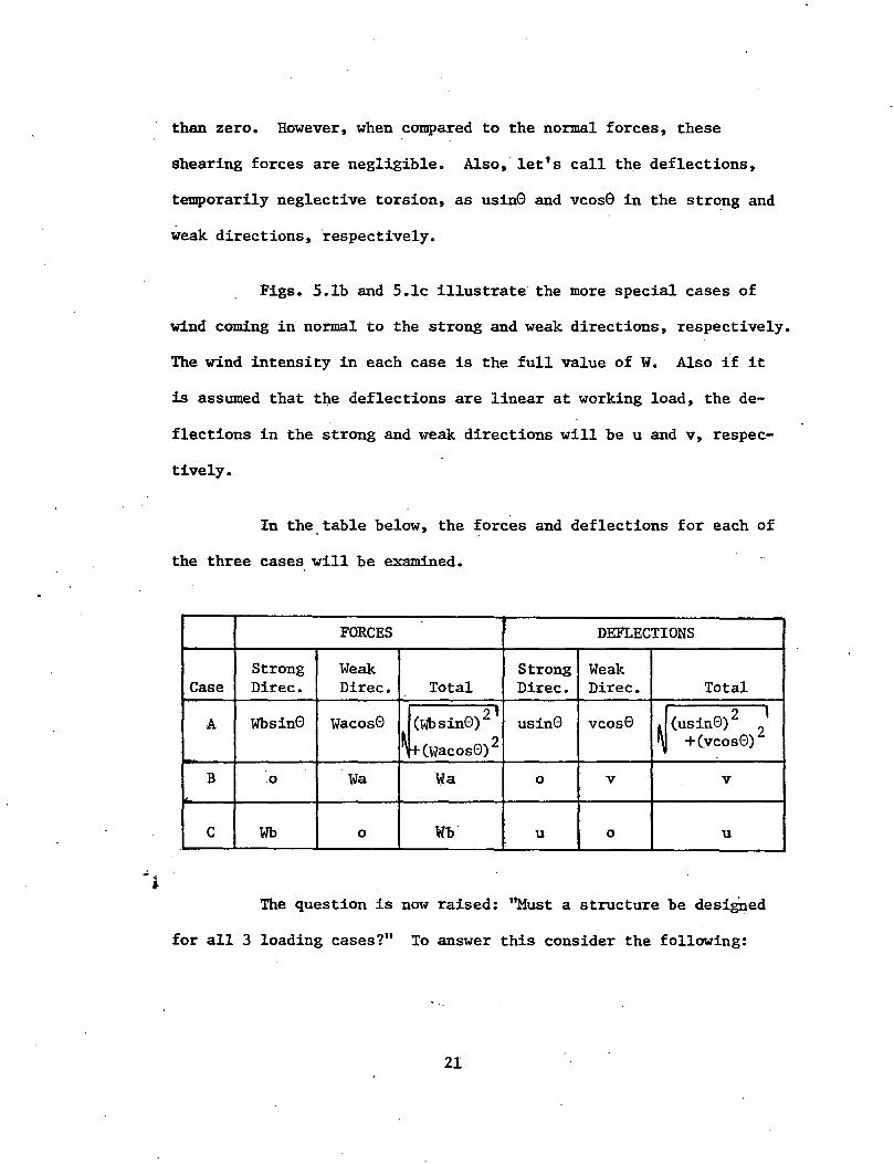
than zero. However, when compared to the normal forces, these
shearing forces are negligible. Also, let's call th~ deflections,
temporarily neglective torsion, as usin0 and vcos0 in the strong and
weak directions, respectively.
Figs. S.lb and S.lc illustrate the more special cases of
wind coming in normal to the strong and weak directions, respectively.
The wind intensity in each case is the full value of W. Also if it
is assumed that t4e deflections are linear at working load, the de-
flections in the strong and weak directions will be u and v, respec-
tively.
In the.table below, the forces and deflections for each of
the three cases will be examined.
FORCES DEFLECTIONS
Strong Weak Strong Weak Case Direc. Direc. Total Direc. Direc. Total
A Wbsin0 Wacos0 (Wbsin0) 2 1 usin0 vcos0 ~ (usin0)
2 2'
1 ~ r+- Cwacos0) 2 +(vcos0)
B .0 wa wa 0 v v
c Wb 0 Wb. u 0 u
The question is now raised: ''Must a structure be desigued
for all 3 loading cases?" To answer this consider the following:
21
~
(1) The total forces and deflections for case A lies be
tween those of cases B and C.
(2) Cases B and C each subject the building frame to its
maximum forces and deflections in their respective wind directions.
(3) The failure envelope for bea~columns is, even using
the most conservative failure theories, a straight line triangular
pattern.
In view of these considerations, it is generally found
that if a building is designed to resist the wind of cases B and C,
that building will be sufficiently stiff for wind coming in at an
angle.
5.2 Deflection Behavior of Frames Under Combined Loading
As was previously discussed, frames have many degrees of
freedom with respect to the ways in which they can deform. For in
stance, the frame may twist, or it may not deflect uniformly along
any one side, or both sides may sway simultaneously. For regular,
symmetric frames, these phenomena also exist, but certain assumptions
can be made to simplify the design process. Assumptions pertaining
j to the following two areas will be examined:
(1) Non-uniform sway.
(2) Torsional sway.
22
5.2a Non-Uniform Sway
Consider the rectangular building frame shown in Fig. 5.2.
It is subjected to a uniform wind loading along its long side, in the
weak direction. Wind resistance is provided by a series of equally
spaced planar bents. In all likelihood,. each of the interior bents
will be of the same stiffness, ~, since they each have the same tri
butary areas for both wind and gravity loads. For these reasons the
end bents will also have the same stiffness, k2• It is difficult to
state whether k2 will be larger or smaller than ~, for th~ following
reasons:
(1) The exterior bents have a smaller tributary area for
gravity and wind·loads. This will tend to make k2 smaller than k1 •
(2) The exterior bents are loaded eccentrically about the
weak direction. This will tend to make k2
_.larger than k1 •
However, in view of these 2 reasons, it is likely that the
stiffnesses of the exterior and interior bents will be close to each
other. Thus, in most rectangular building frames the actual sway de
flections will be as shown in Fig. 5.2: smallest deflections at the
ends, largest toward the center. Although this type of non-uniform
sway deflection could be treated analytically, it is not a practical
•• design approach for the following reasons:
(1) Each of the bents would have to be designed for a dif
ferent value of ~/h. Thus, each of the bents will resist a different
P~ overturning moment.
(2) The frame must be analyzed at factored working loads to
23
check if the sway values assumed for each bent are correct.
In view of these difficulties, it is much simpler to assume
that the building undergoes a uniform sway as shown in Fig. 5.2. Al-
though this is not exact, it is a practical approximation. After all,
floor slabs, walls, partitions and the exterior cladding interact with
the steel Iilembers to tie the building together into "one package".
Under an assumed uniform wind load, all these components will interact
together to try and sway together. Those components which are less
stiff will be carried along by those components which are more stiff.
Thus, it may be concluded that an assumed uniform sway is a reasonable
approximation. The magnitude of what this assumed sway should be will
be discussed in Art. 5.3c.
5.2b Torsional Sway
All frames will experience some kind of externally applied
twisting moment. For unsymmetric irregular frames as shown in Fig.
5.3a, it is obvious that the framework must be designed to resist
these applied twisting moments. In addition, some symmetric, regular
building frames with a central core as shown in Fig. 5.3b must be
designed to resist torsional forces. The reason is· that a slight i~
~ balance in the wind forces may create large torsional moments applied J to the core.
MOst regular,symmetric, unbraced building frames can, how-
ever, be designed neglecting torsion. Although it is true that these
24
i
I $
frames may be subje<:ted to small amounts of torsion due to unbalanced
wind forces created by tuTbulance or suction, these torsional forces
will generally be small. Thus, frames of this type may be designed
assuming the deflection behavior shown in Fig. 5.1. The structure
does not rotate, but simply deflects in the two mutually orthogonal
weak and strong directions.
It will be noted here that special circumstances may dictate
that a regular, symmetric frame may have to be designed considering
torsion. Two of these special circumstances which sometimes occur
are:
(1) Wind being partially obstructred by an adjacent build
ing, thereby setting up a non~uniform external load, as shown in
Fig. 5.3c. This factor has been highlighted by the recent revelation
that wind tunnel studies for a building are often inaccurate if the
adjacent buildings are not included in the model.
(2) A building fastened to an adjacent building, or re
strained in some other manner along one side. As illustrated in
Fig. 5.3d, this sets up unsymmetric boundary conditions which thereby
.induce torsional forces.
5.3 Design of Frames for Sway .:~
In the previous section, it was discussed how the deflection
behavior of building frames will be approximated for regular, s~
metric frames: design for wind separately in the weak and strong
25
•
directions, no torsion and uniform sway. In addition, in Ch. 3, the
plastic design technique using moment balancing was demonstrated. The
purpose of -this article will be to illustrate some of the more general
techniques and principals of designing buildings for sway. Three
areas will be considered:
(1) Designing for sway in the weak direction.
(2) Designing for sway in the strong direction.
(3) Sway limits.
5.3a Sway in the Weak Direction
Referring to Fig. 5.1, wind blowing in the weak direction of
a building is usually the most severe case, for the following reasons.:
1. The wind surface is larger on a face perpendicular to
the weak direction.
2. There are a fewer number of bays resisting the wind
forces in the weak direction.
In view of these factors, it must be realized that control
ling sway in the weak direction is a primary consideration in the
plastic design of unbraced multistory frames. Often, for frames with
a total height to total width ratio H/W greater than 4, the control
~f deflections may control the design, instead of strength. For this
reason, good engineering judgment should be used. Several points will
be listed here as applied to unbraced multistory frames.
26
.~ . •
(1) Do not use an unbraced frame, if at all possible.
Braced frames are much more economical structurally, and are better
able to control drift. Obviously, architectural requirements may
often dictate the use of an unbraced frame.
(2) Orient columns such that their weak axes are in the same
direction as the weak direction of the building. In this way, maximum
resistance to the wind in this critical direction will be providea.
(3) In the weak direction, space the columns as close to-
gether as possible. The importance of this cannot be over-emphasized
and is illustrated in Fig. 5.4. In Fig. 5.4, girders AB and BC are
rigidly fastened at both ends to columns. As the frame sways, two
stories will deflect by an amount 8 relative to one another. Also,
assuming for the purpose of illustration that the girders are of·equal
length, all joints rotate by an amount 0. The girders tend to resist
this joint rotation with a resisting moment called M , where: r
M = 6 EI 0 r L
for both ends fixed and
(5.1)
(5.2)
for one end fixed and one end simply supported. It is these girder
resisting moments, along with any column moments, which resist the
overturning moments due to wind and P8 in a building frame. Examining
equations (5.1) and (5.2) above and Fig. 5.4, observe that shorter
girders of the same EI.will produce a much larger resisting moment,.
27
M , for the following reasons: (1) the shorter girders must go r
through a much larger rotation 8 for the same sway, 6; (2) the
shorter girders will have a smaller value of L.
Thus, for slender frames in which drift may be a problem,
closer spacing of the columns in the buildings weak direction will
greatly reduce the sway. Again architectural constraints of the
floor plan may require wide bays in the interior of a building. Under
these circumstances, the designer may wish to investigate the possi-
bility of using a tube design, in which columns are closely spaced
around the perimeter of a building.
It is important to understand that it is primarily the gir-
ders which resist sway, not the columns. The more flexible the gir-
ders are made (by having bays of 25 feet wide and over), the more
uneconomical an unbraced frame will become, because of the extremely
heavy girder sizes that will be required to resist the sway.
(4) In those bents which are designed to resist wind, it is
preferable to use moment resistant connections at both ends of the
girder if possible. Comparing equations (5.1) and (5.2), a girder
with two fixed connections develops four times the resisti~g moment
capacity (6 + 6 = 12 vs. 3 + 0 = 3) in the elastic range as a girder
•twith only one end fixed. The much larger heavier girders required
when only one end is fixed are usually more expensive than the addi-
tional cost of an extra moment resistant connection.
28
Simple girders may be.economically used, however, in those
bents which are not required to carry wind load. For instance, con
sider the plan view of the building in Fig. 5.5. Calculations may
show that adequate wind resistance can be achieved by using rigid
moment resistant connections in every other bent. The other bents are
called supported bents, and they are assumed to carry no wind. These
supported bents go through a deflection~, but their P~.overturing
moments are assumed to be transferred as P~/h shears through the floor
slabs to the wind resistant bents. In this case, since these bents
carry no overturning or wind moments, the girders may very well be
simply fastened.
Another reason to have only every other bent in a frame as
wind resistant may be for girder depth limitations. In the lower
stories of a building, girders which resist wind become excessively
deep (24" - 36"). They may be hidden as dropped girders in walls,
doorways, or other partitions. Girders which resist no wind, however,
usually impose no severe clear ceiling height problems, as these gir
ders are not required to be very deep.
5.3b Sway in the Strong Direction
Referring to Fig. 5.1, wind blowing in the strong direction
of a building is usually not as critical as wind blowing in the weak
direction, for the following reasons:
(1) The wind surface area perpendicular to the strong
direction is usually smaller. 29
(2) There are a large number of bays resisting the wind in
the strong direction.
For these reasons, it is much less difficult to control de
flections in the strong direction. Since it is rather easy to control
these deflections it is good engineering practice to keep them reason
ably small. The sway deflections should be kept small not only to re
duce the sway motion felt by the occupants, but also to reduce the
P~ overturning moments. By reducing sway, these moment loads will be
reduced, which will allow for a reduction in the required stiffnesses
of the members.
To resist the wind in an unbraced frame, it is necessary to
provide some rigid moment resistant girder connections in the weak
direction of the building. However, because of the smaller wind ef
fect, not all bents and not all bays within the bents need to be wind
resisting. Consider the building frame in Fig. 5.5. In the strong
direction of the building, there are 36 bays. However, the 12 wind
resistant bents shown may be fully adequate to resist the wind and
keep the sway within reasonable limits. For the reasons previously
mentioned, also note that the girder spans in the strong direction
may be longer than those in the weak direction.
It is often architecturally possible to enclose braces be-
tween exterior or interior walls along the strong direction of the
building. When this is possible, bracing will result in a much more
structurally economical solution for resisting wind in the strong
direction than will a series of moment resistant bays. For this
30
·reason, many building frame~ will' be designed as unbraced frames in
the strong direction and as braced frames in the weak direction.
When placing the wind resistant bents, symmetry is an i~
portant consideration. Unsymmetrical placing of the wind resistant
bents will tend to introduce torsion into the building.
Another consideration in the placing of wind resistant
bents is the carry-over of P~/h shears from the supported bents.
Consider Fig. 5.6a. Although the wind resistant bents are spaced
symmetrically, they are not evenly spaced but are bunched up at the
ends of the building. This requires the P~/h shears induced in the
supported bents near the middle to be carried through the floor slabs
all the way to the end wind resistant bents. A much better~ more
equal spacing of the same number of wind resistant bents is shown in
Fig. 5.6b. Each of the supported bents is adjacent to a wind resis~
tant bent.
5.3c Sway Limits
In the previous sections, the actual d.eflection behavior of
frames has been discussed. Also shown was how and why a simplified
.:.j.deflection behavior pattern can be assumed for regular, symmetric
frames. In Article 3.2a, the subassemblage method of analysis for
calculating the magnitudes of sway deflections in unbraced frames was
briefly discussed. Using this method, one is able to arrive at the
lateral load versus drift relationship for a story in a frame.
However, one of the problems which has not yet been resolved
in unbraced, plastically designed frames is the magnitude of allowable
sway indices, ~/h, under working load. Referring to Ch. 3, the plas
tic design technique is based on assuming a value of ~/h at factored
loads. For a conservative design, this value of ~/h is usually
assumed to be a much larger value than the actual sway at. ultimate
load. A value of 0.01 is often assumed for ~/h in the design. After
the frame is designed, several stories in the frame are analyzed using
say the subassemblage technique, to calculate their lateral load
versus drift relationship. For ordinary design, the sway at ultimate
is usually much less than the initial assumed design sway. At working
wind load (the gravity loads are assumed to remain at a constant
factored level of 1.3 throughout the sway behavior of the structure)_
typical sway indices range from 0.002 ~ ~ ~ 0~005 •.
The question is now asked, '~at is a reasonable acceptable
sway index at working load?" To answer this question, three items
must be considered:
(1) The sway must be small enough at working load to pre
clude the formation of any plastic hinges in the structural mem0ers
themselves.
(2) The,sway at working load must be small enough to pre-
vent damage to non-structural building components, such as walls,
windows, ceilings, utilities, etc.
(3) The sway at working load should be small enough to
ensure no occupant discomfort due to motion.
32
·From the load ve~sussway relationship obtained from the
subassemblage analysis, it is a simple matter to check item (1) above.
For most designs, a hinge will seldom occur below the working load.
Item (3) also imposes no problems for usual unbraced frames. This is
because occupant discomfort is caused by the amount of total sway, not
the relative story sways. Since an unbraced frame is structurally
economical only for buildings below about 30 stories, the total build-
ing sway is usually well below the human discomfort limit. Consider-
ation of item (2),however, is a much more difficult problem. In the
' early days of tall building construction, a sway index of 0.002 was
often used as a guideline. The modern era of tall buildings, however,
differs from the early era in two important respects. First, today's
buildings have a lighter, more flexible frame coupled with a lighter,
exterior frame. In the old days, buildings were often designed using
high factors of safety and were usually shrouded in a very heavy
masonry or stone cladding. For this reason, deflection problems
were justifiably considered to be of secondary importance. The re-
quirement of a sway index of 0.002 was often easily met.
The second difference between the two eras is the methods
of desigp. The overturning P~ moments were usually not considered
in the early days, but they form an additional loading in the present ~~
plastic design technique.
In view of these differences, there seems to be no logical
reason why an allowable working load drift index of 0.002 should be
used as the performance criteria for to~ay's plastically designed
33
• i
frames. For most plastically designed frames, the member sizes would
have to be extremely large to meet this criteria. It is the author's
opinion that an index of between 0.003 and 0.004 may be a reasonable
criterion.
5.4 Biaxial Bending of Columns Under Combined Loading
In Chapter 4 it was discussed how biaxial bending in
columns could occur when subjected to gravity loads. Often, the
most critical condition of biaxial bending in some columns will
occur under combined loading.
Consider the building frame in Fig. 4.1. For wind loading
in either the strong or weak directions, the following columns will
be subjected to biaxial bending: Al, Bl, Cl, A2, B2, C2, A5, B5, C5,
A6, B6, and C6. Three cases will be examined below:
(1) Column Al with wind in the weak direction. Column Al
is a corner column framed by two spandrel girders. With wind in the
weak.direction, the spandrel between column Aland Bl carries wind
'and gravity loads. The typical bending moment diagram of this girder
is illustrated in Fig. 3.6. The spandrel between c~lumns Al and A2
carries only gravity loads, and has a bending monent diagram as
shown in Fig. 3.1. The resulting free body and bending moment
diagrams for column Al are shown in Fig. 5.7. Notice that M3 will
probably be greater than MI' since the wind load is greater at the
lower level.
34
· (2) Column Bl with wind in the weak direction. Column Bl
' is an edge column framed by two spandrel girders and one floor gir
der. The spandrel girders carry gravity and wind loads, and their
typical bending moment diagrams are illustrated in Fig. 3.6. The
floor girder carries only gravity load, and has a bending moment
diagram as shown in Fig. 3.1. The resulting free body and bending
moment diagrams for column Bl are shown in Fig. 5.8. Only the top
joint of the column is illustrated. A similar situation would occur
at the lower joint of the column. Notice that Mpl and M2 add to
produce a large moment about the column's strong axis.
(3) Column B2 with wind in the weak direction. Column
B2 is framed by four floor girders, three of them being rigidly
fastened. The two floor girders in the weak direction carry wind and
gravity loads. 'The tw? girders in the strong direction carry only
gravity loads. Only one of the floor girders in the strong direction
is rigidly fastened. The resulting free body and bending moment dia
grams for column B2 are shown in Fig. 5.9.
The above cases serve only to illustrate some of the ways
in which columns can be subjected to biaxial bending under wind
plus gravity loads. Many other cases exist, but they are similar to
those illustrated here.
In Chapter 8 a design example will illustrate some of the
three-dimensional effects for a symmetric frame subjected to combined
loading.
35
6. PRACTICAL PLASTIC DESIGN OF COLUMNS UNDER BIAXIAL BENDING
As was observed in Chapters 4 and 5, columns are often
subjected to biaxial bending. Fig. 6.1 illustrates the end moments
and axial load on a typical column subjected to biaxial bending. ·The
problem is to develop a practical design approach to select the re-
quired column section. In the past, it was usual practice to select
somewhat larger, over-designed sections for those columns subjected to
biaxial bending. This was either the result of extremely conservative
interaction equations, or a fear on the part of the designer that bi-
axial bending was a very dangerous loading condition, and hence re-
quired larger sections. Even for frames which used a plastic design
approach, columns in biaxial bending were often designed elastically.
During the past several years, considerable research has
gone into predicting the ultimate strength behavior of columns in
biaxial bending. In this chapter, some of the more recent develop~
ments will be examined, and a practical design approach for unbraced
frames is given.
6.1 Development of Interactiori Equations
The capacity of a column under biaxial. bending will be
limited by one of two criteria: '"t
1. Strength - This criteri<)n usually controls short
columns (small L/r ), or medium length columns y
bent in reverse curvature about both axes •. ·
2. Stability-. This criterien usually-controls slender ·~ ... ~~.,i... ·:··:-·· .. "
columns (large ttry), or medium
length columns bent in single curvature about
one or two axes.
Solutions for columns subjected to uniaxial bending are
-available, and interaction equations have been developed which
agree well with theory and tests. The solution for column
capacities under biaxial bending, especially in the inelastic range,
has proven to be a much more difficult task, however. Reference
14 gives a review on the solution to this problem. In this
section only some of the more recent developments will be briefly
examined. The solutions to strength and stability will be e~
amined separately.
6.la Strength Interaction Equations
Recently several approaches have been used in an attempt
to define an exact solution for the capacity of wide-flange
columns of zero-length. Ref. 15 has categorized these approaches
into three groups:
1. An equilibrium approach which was developed by·
Ringo (Ref. 16) and by Pfrang and Toland (Ref. 17.) For a pre-
determined set of locations and angular rotations, P, M , and M were X y
evaluated. Interaction diagrams were then constructed for speci-
fie wide-flange shapes.
2. An analytical approach developed by Morris and
Fenves (Ref. 18)which related P, M and M to various locations X y
of the neutral axis. Santathadaporn and Chen (Ref. 19)formulated
37
dimensionless interaction curves for these equations which they
demonstrated to be independent of various width to depth and flange
thickness to depth ratios for wide-flange shapes.
3. An approach by Chen and Atsuta (Refs. 20 and 21)
and more recently by Chen and Tebedge (Ref. 22) have been based on
superposition. By defining a solution for a rectangular shape,
they demonstrated that the solution for any shape could be obtained
by substracting rectangular areas from an original rectangular
shape.
The exact solutions obtained by these three groups were
all in agreement, and the interaction curve obtained is illus-
trated in Fig. 6. 2.
Up until very recently, linear expressions have been
used in the design of columns under biaxial loading. For instance,
the CSA Specification (R,ef. 34) uses the following e<!J:Uati:ons for.
column strength capacity:
p p
y + 0.85 Mx
M px
M p .. + 0.85 J.... ~ 1.0, for P ~ 0.·15
Mpy y
M M . P ~ + J.... < 1.0, for p > 0.15 M M y
px PY
(6.1)
(6.2)
~i At present the AISC Specification has no criteria for the ultimate
strength design of biaxial bending. However, if the AISC Speci-
fication working strength equation were factored by 1.67, an
equation similar to that of the CSA Specification would be obtained. The extreme conserv~§ism of Eq. 6.1 is shown in Fig. 6.2.
Notice how the capacity is grossly underestimated when compared
with the exact interaction curves.
One reason that Eq. 6.1 is so conservative is that it ·
assumes the same relationship exists between M /M and P/P Y PY Y
as between M /M and P/P • In fact, the relationship is differ-x px y
ent for the weak and strong axes. As given in Refo 4, the
relationship is: '·
M Mpcx . = 1.18
px
M _.££I. M
PY
=·1.19
p (1- p)
y
[1-{~) 2 J
(6.3)
(6.4)
To correct for the strong and weak axis differences,
Pillai (Ref. 23) recommended the following equation:
: + 0.85 Mx + 0.60 ~ ~ 1.0, for : ~ 0.15 (6.5) M M . y px py y
is plotted (together with Eq. 6.2 to limit the maximum Eq. 6.5
~/Mpy = 1.0) in Fig. 6~2. Although Eq. 6.5 allows much higher
capacities than Eq. 6.1, it is nevertheless extremely conservative.
From Fig. 6.2 also note that Eq. 6.5 appears to be the best
approximation possible using linear terms.
In an attempt to more closely approximate the inter-
.; f. action T b d d Ch (R f 22) h d h curves, e e ge an en e • ave suggeste t e
following interaction equation:
39
where:
a = 1.6 -
a =·1.0,
+(~ ·Yl < 1.0 pcy.
p p
y 2.0
for
ln (:} , for 0.55 < bf
d
y b b
f < 0.55 or f > 1.0 - -d d
bf = flange width of column
d = depth of column
{6.6)
< 1.0 {6.7)
{6.8)
In Fig. 6.2 Eq. 6.6 is plotted for a wide-flang.e section which
meets the requirements of Eq. 6•7. Notice the much better
agreement of Eq. 6.6 with the exact solution, and the much higher
capacity which it allows than any of the presently formulated
interaction curves. It may be of interest to note that if Eq. 6.6
were used with a= 1.0, {very conservative, linear case), it
would be the same as the interaction equation formerly used by
the CRC guides {Refs. 15 and 24)o
In this thesis, Eq. 6.6 will be used as the strength
design criteria for biaxial bending of columns·. It gives
excellent agreement with the theoretical solution. In addition,
it has recently been proposed for acceptance in the AISC Speci-
fication.
40
·~-~.:·=-·;{::-.- ·._ ...
6.lb Stability Interaction Equations
In Article 6.-la. the solution to the problem of maximum
strength capaci_ty of "wi¥-;:-flange columns under biaxial loading has been
discussed. These solutions have precluded, however, any type of
stability failure prior to the attainment of the ultimate column capa-
city. Past experience with columns subjected to uniaxial bending tells
us that columns may buckle laterally and torsionally prior to the
attainment of their ultimate capacity. Solutions proposed to define
this type of behavior for columns under biaxial bending will be dis-
cussed in this article.
Differential equations for the elastic region were first
formulated by Good~er (~ef. 25). These equations were solved exactly
by Culver (Refs. 26 and 27) and were solved approximately by several
other investigators.
In the inelastic range, numerical· -• procedures to obtain
the maximum capacity have been used. Most recently, Chen and Santa-
thadaporn (Ref. 28) used an incremental approach which considered
yielding of the material, residual stresses, end warping restraint,
end bending restraint, and initial imperfections. This solution
was compared to the analytical solutions of Birnstiel (Ref. 29, 30,
31) for which excellent agreement was obtained. In addition, the
solution of Chen and Santathadaporn was found to give excellent
agreement with existing test results.
Based on the_solution of Chen and Santathadaporn,
Tebedge and Chen (Ref. 22) prepared interaction curves for a 41
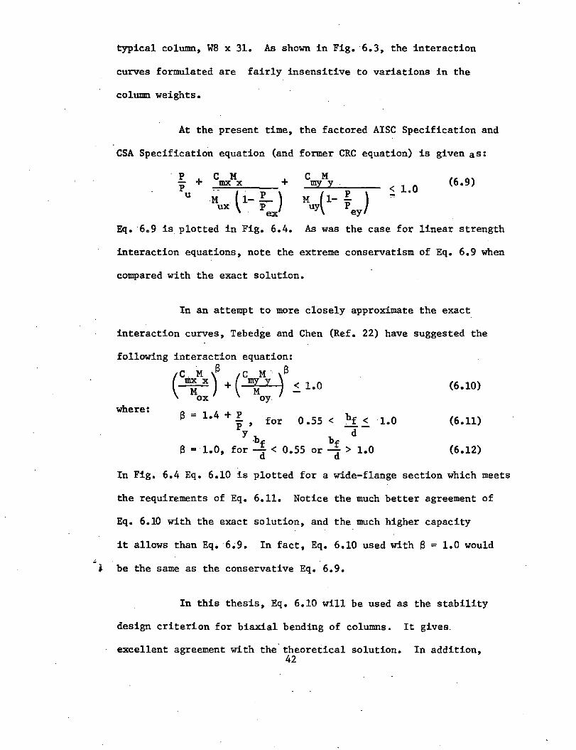
typical column, W8 x 31. As shown in Fig. 6.3, the interaction
curves formulated are fairly insensitive to variations in the
column weights.
At the present time, the factored AISC Specification and
CSA Specification equation (and former CRC equation) is given as:
P + C M + P .,-Fmx=-~x;.._. __
u .li . ti-!..) ux p . ex
C M myy
< 1.0 (6.9)
Eq. 6.9 is plotted in Fig. 6.4. As was the case for linear strength
interaction equations, note the extreme conservatism of Eq. 6.9 when
compared with the exact solution.
In an attempt to more closely approximate the exact
interaction curves, Tebedge and Chen (Ref. 22) have suggested the
following interaction equation:
where:
(c"';.Mx) + (~B < ox oy.
1.0
13 = 1.4 + p f p , or
y -bf
13 = 1.0, for ~ <
0 .55 < bf < d
bf 0.55 or ~ > 1.0
(6.10)
1.0 (6.11)
(6.12)
In Fig. 6.4 Eq. 6.10 is plotted for a wide-flange section which meets
the requirements of Eq. 6.11. Notice the much better agreement of
Eq. 6.10 with the exact solution, and the much higher capacity
it allows than Eq. 6.9. In fact, Eq. 6.10 used with 13 = 1.0 would
i be the same as the conservative Eq. 6.9.
In this thesis, Eq. 6.10 will be used as the stability
design criterion for biaxial bending of columns. It gives.
excellent agreement with the. theoretical solution. In addition, 42
.:. J.
it has recently been proposed for acceptance in the AISC Specifi-
cation (Ref. 32).
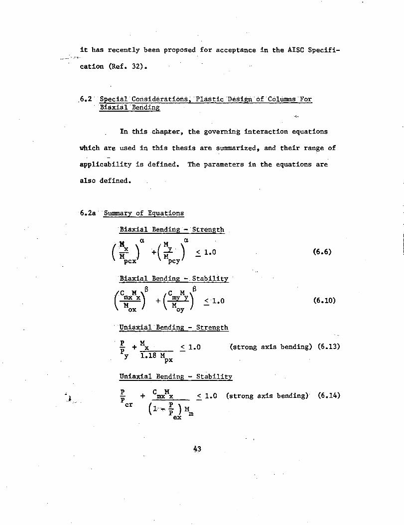
6.2 Special Considerations, Plastic Design of Coltimns For ·Biaxial.Beriding
... ~ ..
In this cha~~, the governing interaction equations
which are used in this thesis are summarized, and their range of
applicability is defined. The parameters in the equations are
also defined.
6.2a Summary of Equations
·Biaxial·Bending -·strength
. :M a M a
( X ) . ( J_ . ) < 1.0
Mpcx· + Mpcy
Biaxial Bending -.Stability
(
C M S c M S : x) + ( :Y Y) 2_ 1.0 ox oy
· Uniaxial Bending - Strength
P + Mx < 1.0 py 1.18 M
px
(6.6)
(6.10)
(strong axis bending) (6.13)
Uniaxial Bending Stability
p p cr
C M + mx x < 1.0 (strong axis bending)· (6.14)
( 1··~ ~ ) Mm ex
43
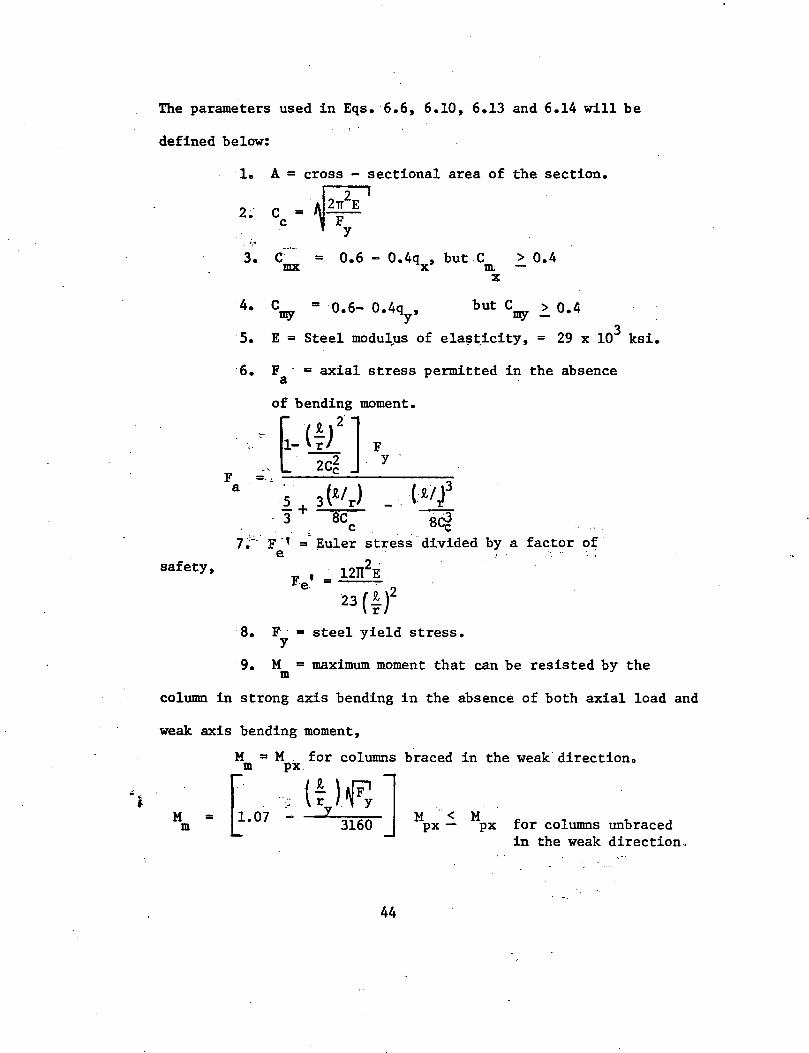
The parameters used in Eqs. 6.6, 6.10, 6.13 and 6.14 will be
defined below:
safety,
1. A = cross - sectional area of the section.
2; Cc = ~z;2E I y
F a
3. C = 0.6 - 0.4q , but C . > 0.4 mx x DL
X
4. but cmy > 0.4
s. 3 E = Steel modu~us of ela~~icity, = 29 x 10 ksi.
6. F = axial stress permitted in the absence a
of bending moment.
'C.J!J:].Fy _, l 2Cc
1 + 3 (t/ r) 3 sc
c Tf- F ·' =· Euler stress divided by a factor of e ..
12rr2
Fi
23 (; )2
F.e.' =
8. F · = steel yield stress. y
9. M = maximum moment that can be resisted by the m
column in strong axis bending in the absence of both axial load and
weak axis bending moment,
M m =
M = M . for columns
( :X(!~~ J ~- 07 ~ 1 316~
braced in the weak.directiono
M < M px - px for columns unbraced in the weak direction,
'
.. j.
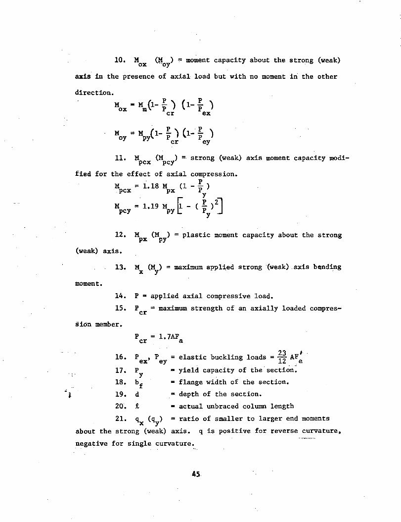
10. M ox (~0y) = mom~nt capacity about the strong (weak)
axis in the presence of axial load but with no moment in the other
direction.
M = M (1- p ) ox m P (1-: )
cr ex
M0y = M ( 1- : ) (1-· : )
py cr ey
11. M (M ) = strong (weak) axis moment capacity· modi-pcx pcy
fied for the effect of axial compression.
M = 1.18 M (1 - : ) ·. pcx px y
M = 1.19 M ~ - ( pp )2]
pcy PYL y
12. Mpx (MPY) = plastic moment capacity about the strong
(weak) axis.
moment.
13. M (M ) = maximum applied strong ·(weak) . axis be.nd~g X y
14. P = applied axial compressive load.
15. P = maximum strength of an axially loaded comprescr
sion member.
16.
17.
18.
19.
20.
P = 1. 7AF cr a
p ex'
p y
bf d
t
23 I Pey =elastic buckling loads= 12 AFe
= yield capacity of the section:
= flange width of the section.
= depth of the section.
= actual unbraced column length
21. qx (~) = ratio of smaller to larger end moments
about the strong (weak) axis. q is positive for reverse curvature,
negative for single curvature.
45.
I I
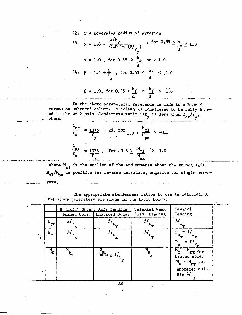
22.
23.
24.
r = governing radius of gyration · .:.P/P ...
a Q 1•6 - ·2.0Yln (P/P )
y
, for 0.55 ~ bf < l.O
d
a = 1.0 , for ·0.55 -> bf· or > 1.0
p a =·1.4 +'P y
·r , for 0.55 ~ bf < 1.0
d
a 1 o ·f ·0.55 > bf j.) = • , or or bf -·> i-~-0 d _4
In the above parameters, reference is made to a braced versus an unbraced column. A column is considered to be fully brae
. ed if the weak axis slenderness ratio 'Mr is less than R, /r , · y cr y where. . . -- --···---- - -- . ·- -- ~-
• i
R,cr = r y
1375 + 25, for . Mxl F 1.0 > M· > -0.5
y px
R. :....££ r y
= 1375 , for -0.5 > Mxl > -1.0 F M .
. - .¥. .. ------····-·- , .. - --. _____ p~_. ---------------where Mxl is the smaller of the end moments about the strong axis;
M_~/M is positive for reverse curvature, negative for single curvaA.L px
ture.
The appropriate slenderness ratios to use in calculating . · the above parameters are given in the table below.
Uniaxial Strong Axis Bending Uniaxial Weak Biaxial Braced Cols. Unbraced Cols. Axis Bending Bending
p 'M R-1 u u cr r r r r X y y y
p if R,f R./ p = u e r r r e r
X X y x· X
p = R-1 -. e~ rv
.11 -x .M M }1 - .M 11} p-x m.
1./r py m px for US1ng braced cols.
y M =M for m PY
unbraced cols. use 1/r
y
46
~ . j.
6.2b Applicability of Equations
There are several special provisions which are not
immediately evident in Equations 6.6, 6.10, 6.13 and 6.14, but
which nevertheless are extremely important. These provisions
will be considered here.
(1) Local Buckling - Member instability due to local
buckling prior to the attainment of the ultimate capacity of the
member is avoided by selecting only those sections specified as
compact by the AISC Specification (Ref. 32). Design Aid I
(.DA-I) in Appendix 1 lists the properties of all column sections
which meet the compact section requirements.
(2) Effective Length Factor, K - Note that in the
parameters defined for use in Eqs. 6.6, 6ol0, 6.13 and 6.14, a
column effective length factor of K=l has been used. This is
allowed provided the secondary PfJ. moments are included in the
design (Ref. 33).
(3) Maximum Axial Load Ratios - The maximum column
axial load ratio, P/Py' shall not exceed 0.75. This provision
is included, based on the work reported in Ref. 33, to safeguard
against the following four effects:
(a) Gravity load instability in the upper stories of
the frame.
(b) Loss of stiffness due to residual stress.
(c) Extensive yielding of the column ends at the
factored load. 47
• • - --~. ~-- -
. (d) Lateral - torsional buckling
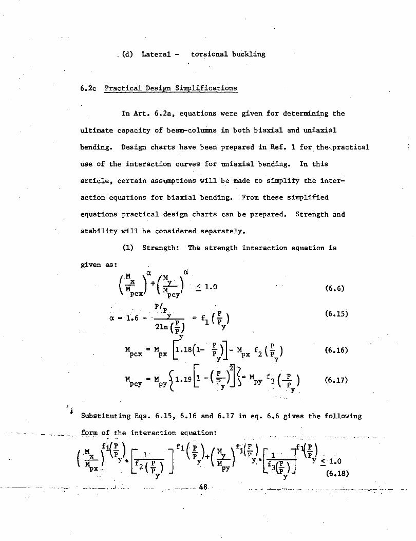
6.2c Practical Design Simplifications
In Art. 6.2a, equations were given for determining the
ultimate capacity of be~columns in both biaxial and uniaxial
bending. Design charts have been prepared in Ref. 1 for. the,practical
use of the interaction curves for uniaxial bending. In this
article, certain assumptions will be made to simplify the inter-
action equations for biaxial bending. From these simplified
equations practical design charts can be prepared. Strength and
stability will be considered separately.
(1) Strength: The strength interaction equation is
given as:
( Mx )'\(L) d.· < 1.0 M . M ,
pcx pcy
P/ a = 1.6 -
. p .. y ·p
2ln ( P) y
Mpcx = Mpx E-18(1- ~)} Mpx £2 ( ~Y)
M = M ~1.19 ~ - ( ~)~(= M · f 3• .(·~ ) pcy py [ P j) PY p
.Y .- . y .
(6.6)
(6.15)
(6.16)
(6.17)
Substituting Eqs. 6.15, 6.16 and 6.17 in eq. 6.6 gives the following
f~rm of the interaction equation:
__ , _______ , .. .) . .' .... · .... ..- .. ~ 46 .. ----·- ·--'----:--· .. -------·- ·-- :··----- ·----------= -~ ·---
So, for any given value of P/P.y' an exact relationship between
M /M and M /M is given by Eq. (6.18). The resulting interaction X px Y PY
curves are plotted in Appendix I, DA-II.
Note that the only approximation which was made in
preparing the strength interaction curves in DA-II is that
o.ss ~ bf/d ~1.0. In DA-I are listed all those column sections
which are classified as compact by the AISC Specification (Ref. 32).
From DA-I observe that the bf/d requirement is met for all but 10
of the intermediate weight 14 inch wide-flange sections. These
10 sections have a bf/d ratio ranging from 1.01 to 1.05. The reason
an upper limit of 1.00 was set for bf/d is that this was the upper
limit of the columns which were tested during the formulation of
the interaction equation. Since the worst value of bf/d equals .
1.05, the author feels that this slight variation should not,require
the strict.limitation of et equal to·l~O. Thus, it is reasonable
that all the column sections in DA-I may be acc~rately designed for
strength by the interaction curves of DA-II.
The procedure for using the strength interaction curves
of DA-II for given values of P, ·M and M is: X y
(a) Select a trial section size from DA-I.
(b)
(c)
Calculate P/P and M /M ratios. Y Y PY .
From DA-II read off the M /M ratio, and calculate x px
the M capacity of the column. X
49..
(d) If the M capacity is > the required M , the section X . X
is o.k. for strength (maybe try. a lighter section). If theM X
·capacity is. < the required M , select a larger section from DA-I X
~d repeat the steps above.
Although the design is a trial and error process, DA-II
permits the rapid checking of a section for strength with a minimum
of calculations. Some column design examples are given in Appendix i
II.
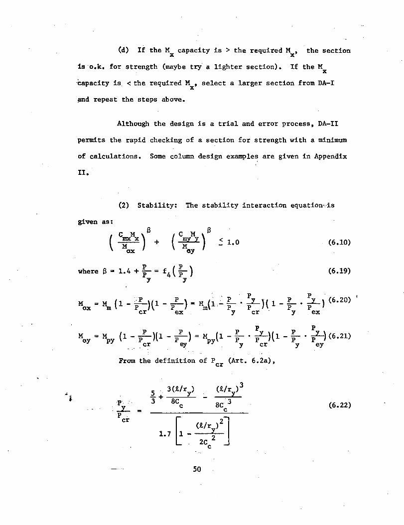
(2) Stability: The stability interaction equation·-·is
given as:
( c M a c M ) a :X) + ( w y ~ 1.0
ox ey (6.10)
where a= p 1.4 + p = f4 ( ~ ) (6.19)
y y
p p - I
M = M ( 1 - l)t 1 - ....!:.._) = M (L~ ~ • _L_ }( 1 - ~ • ~) (6.20) ox m P \ P m . P P . P P cr ex . y cr - y ex
M = M (1- pp )ll - pp ) = M (1 - ~ • :y ){1 - ~ • :y) (6.21) oy PY _ cr ey PY y cr y ey
From the definition of P (Art. 6.2a), cr
p·. ·_J_ =
p cr
5 . 3(1/r ) . y
3+ 8C c
50
(6.22)
. ··w 21T E where C = --c F . y
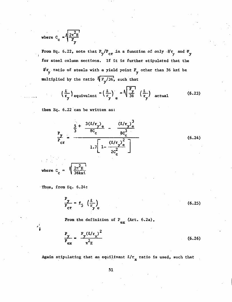
From Eq. 6.22, note that P_ /P is_ a function -Of .only --R/r and :P 1
y cr y y
for steel column sections. If it is further stipulated that the
9/r . ratio of y
steels with a yield point F y
other than 36 ksi be
multiplied by the ratio ~ F /36~ such that y
1 1 . ' fF:1 1 { r ) equivalent = ( r) . = ·~ Jt ( r)
Y Y e Y
then Eq. 6.22 can be written as:
5 + 3{1/r ) l e
(1/r ) 3 I e
p 3 ac 8C3 c .J... c = p
1.{ 1- (1/r )2
J cr
-:t.. e
2c2 c
where Cc = ~
·Thus, from Eq. 6.24:
p J_= f p 5 (! ) cr y e
From the definition of P (Art. 6.2a), ex
p J_= p
ex
actual (6.23)
(6.24)
(6.25)
(6.26)
Again stipulating that an equilivant 1/rx ratio is used, such that
51
. (6.27) actual
Eq. 6.26 becomes:
P 36ksi(t/r ) 2
_J__ = x e = f6 ( tr- ) Pex n2E x e
(6.28)
Likewise it can be shown that
\
(6.29) e
Substituting Eq~-6.25, 6.28 and 6.29 in Eqs. 6.20 and
6.21 gives the following:
M =M ox m [ 1 - !..._ • f (!.._) J ~ -!..._ • f ( !_) "] P 5 r . P 6 r y ye y x e·
M ·f~ (t)] = py 9P r e y, y
(6.30)
(6.31)
Consider now the maximum strong axis bending moment term
M in Eq. 6.30. From Art. 6.2a, m
M • M , braced columns m px
M = rl. 07 - ~ ~] M ::: M , unbraced columns m ~ 3160 px px
52
(6.32}
(6.33)
. <
.:. j
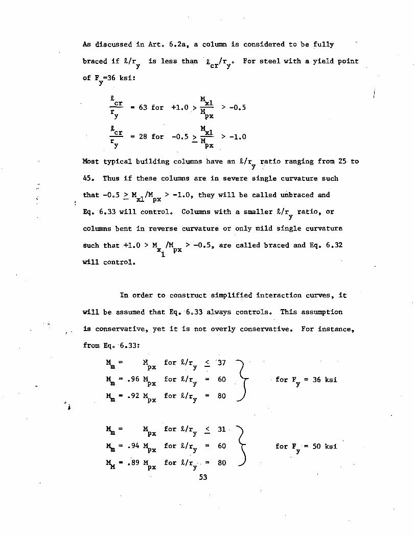
As discussed in Arto 6.2a, a column is considered to be fully
braced if 1/r is less than 1 /r o For steel with a yield point y ·cr y
of F =36 ksi: y
1 Mxl cr = 63 for +1.0 > -o.5 >--r . M
y px
R,cr 28 for
Mxl > -1.0 = -o.5 ~ M r y px
Most typical building columns have an 1/r ratio ranging from 25 to y '/
45. Thus if these columns are in severe single curvature such
that -Oo5 > Mxl/M > -1.0, they will be called unbraced and - px
Eq. 6.33 will controlo Columns with a smaller 1/r ratio, or y
columns bent in reverse curvature or only mild single curvature
such that +1.0 > M /M > -0.5, are called braced and Eq. 6.32 :xi px
will control.
In order to construct simplified interaction curves, it
will be assumed that Eq. 6o33 always controlso This assumption
is conservative, yet it is not overly conservative. For instance,
from Eqo 6.33:
M = M for 1/r < '31
} m px - y -M = .96 M for 1/r = 60 for F = 36 ksi m px y y
M.n= .92 M for 1/ry = 80 px
M.n= M for 1/r < 31
~ px y
M.n= .94 Mpx for 1/ry = 60 for F = 50 ksi y
~- .89 M for 1/r-- = 80 px y 53
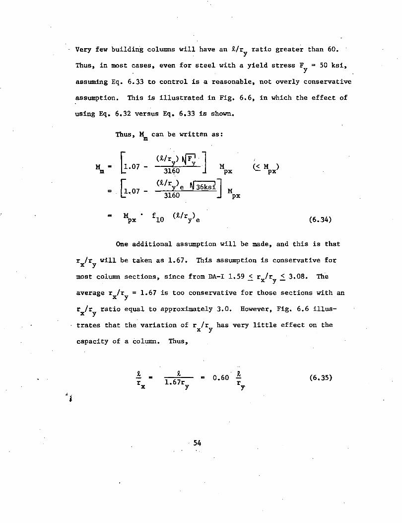
Very few building columns will have an £/r ratio greater than 60. y
Thus, in most cases, even for steel with a yield stress F = 50 ksi, y
assuming Eq. 6.33 to control is a reasonable, not overly conservative
assumption. This is illustrated in Fig. 6.6, in which the effect of
using Eq. 6.32 versus Eq. 6.33 is shown.
M = m
=
=
Thus, M can be written as: m
G-07 (!/ri) ~. J 3160
M
G.07-
M px
(£/r ) N 36kst] ~ e 3160
(R./r ) y e
px
M px
I
(< M ) - px
(6.34)
One additional assumption will be made, and this is that
r /r will be taken as 1.67. This assumption is conservative for X y
most column sections, since from DA-I 1.59 < r /r < 3.08. Th-e - X y-
average r /r = 1.67 is too conservative for those sections with an X y
r /r ratio equal to approximately 3.0. However, Fig. 6.6 illusx y
trates that the variation of r /r has very little effect on the X y
capacity of a column. Thus,
- = r
X 1.67r
y =
54
0.60 fl. r y
(6.35)
~
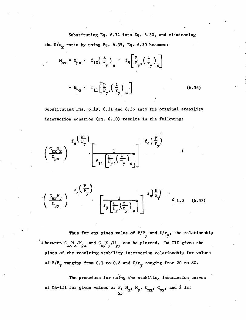
Substituting Eq. 6.34 into Eq. 6.30, and eliminating
the R./r ratio by using Eq. 6.35, Eq. 6.30 becomes: X
M =M ox px fa[: , (! ) J y y e
= M • px f [p (! ) J 11 P , r · (6.36) y y e
Substituting Eqs. 6.19, 6.31 and 6.36 into the original stability
interaction equation (Eq. 6.10) results in the following:
+
~ 1.0 (6.37)
Thus for any given value of P/P and t/r , the relationship y y
;. between C M /M and C M /M can be plotted. DA-III gives the mx x px my y py .
plots of the resulting stability interaction relationship for values
of P/P ranging from 0.1 to 0.8 and R./r ranging from 20 to 80. y y
The procedure for using the stability interaction_curves
of DA-III for given values of P, M , M , C , C , and R. is: x y mx my 55
..
(a)
(b)
(c)
Select a trial se.ction size from DA-1.
Calculate P/P , C M /M , and t/r ratios. Y my Y PY Y
From DA-III read off the C M /M ratio, and mx x px
calculate the M capacity of the column. (Fig. 6.5 and 6.6 illusx
trate there is a smaller percentage error when·reading off the
C M /M value versus calculating this value and reading off the mx x px
C M /M value). my Y PY
(d) If the M capacity is > the required M , the section X X
is o•k. for stability (maybe try a lighter section). If the·M X
capacity is < the required M , select a larger section from DA-I X
and repeat the steps above.
As for strength, the design for stability is a trial and
error process. DA-III greatly reduces, however, the calculations
required for checking the capacity of a section. Some column
design examples are given in Appendix II.
Chapter 8 illustrates the plastic design concept for some
typical members· in a symmetric building frame. How biaxial bending
might typically occur in columns is shown. The practical plastic de-
sign of these columns using the previously developed design aids is
illustrated • ..:i
56.
· 7. RESEARCH NEEDS
In this thesis some of the fundamental three-dimensional
effects occurring in symmetric unbraced frames have been examined.
The practical plastic design of columns in biaxial bending was
illustrated. The study of these topics is only a beginning. There
are many other areas which require additional research before the
plastic design of unsymmetric space frames can become a practical
design office technique. These areas are:
1) The effect of torsion on the ultimate strength
behavior of individual members. At the present time the ultimate
strength behavior of column sections can be accurate~y predicted
for only three load components: axial load, strong axis bending,
and weak axis bending. Torsional forces on the ends of a member
will require the development of a failure criterion to include
this additional load. The derivation of new interaction equations
which include torsion, and which can be practically utilized in
design, are also needed.
2) The effect of torsional forces on the overall
behavior of a frame. The present plastic design approach
assumes that no twisting of the frame occurs under wind loading.
For unsymmetric frames or for some special cases of symmetric
frames (see Art. 5.2b) this assumption is invalid. The plastic
design technique will require modification to account for twist
ing action of the frame.
57
3) The sway deflection behavior of a frame when some
of the columns are subjected to biaxial bending. The subasse~
blage method described in Art. 3.2a can be used to predict the
load vs. deflection behavior for an individual story in a frame.
This method as well as other methods consider only uniaxial bending
of the columns. The additional bending moment caused by biaxial
bending will probably reduce the stiffness of the column against
sway, but to what degree it is not yet known. A discussion of the
subassemblage technique for asymmetric frames is given in Ref. 35.
4) Some type of rational method for determining if a
building has sufficient stiffness to adequately resist sway. The
present emphasis is to estimate a building~ sway deflection index,
A/h, and compare it to a limiting sway deflection index (see
Art. 5.3c). As indicated in Art. 5.3c, there is no unique,
acceptable, rational limiting sway deflection indexo Perhaps
instead of being concerned with a buildings sway index, more atten-
tion should be focused on evaluating the building structure as a
whole against existing building structures. Buildings which have
been successfully completed in the past using plastic design
should be used as a standard against which future buildings can be
compared. When it is shown by past successes that the plastic
~ design technique results in an acceptable building design, less i
emphasis on evaluating and comparing a buildings sway deflection
index is needed.
5) Including the added stiffness of a building's floor
58
slabs, interior walls, and exterior cladding. Traditionally otily
the stiffness of a bare metal ·frame is considered. A method is
needed for determining how and to what degree these secondary
stiffening elements combine with the frame to resist externally
applied loads.
6) The effect of floor slabs acting compositely with the
floor girders through the use .of shear stud connectors. A method
for considering the plastic behavior of these composite sections
is needed.
7) Distribution of P~/h shears from a supported bent
to a wind resistant bent. It is usually assumed that the P~/h
shears in a supported bent are completely transferred through the
floor slabs to a wind resistant bent. Since a supported bent will
probably never be subjected to its factored gravity design load~~
it inherently has some stiffness to resist the wind as well as the
P~/h shears. The magnitude of this resistance · and how it affects
the overall behavior of a building is not yet well understood.
Many of the research needs discussed above apply.not
only to plastic design but to elastic design as well. From the
above it may appear that there is much which is not known about /...:
• the behavior of a building. The picture is not all that bleak,
however. After all, buildings have been and will be constructed
using somewhat primitive design techniques, but as long as these
buildings stand up and serve their intended purpose, then the
59

design is an acceptable one. Plastic design is simply an effort
to make a more economical acceptable design.
60

8. DESIGN EXAMPLE
61
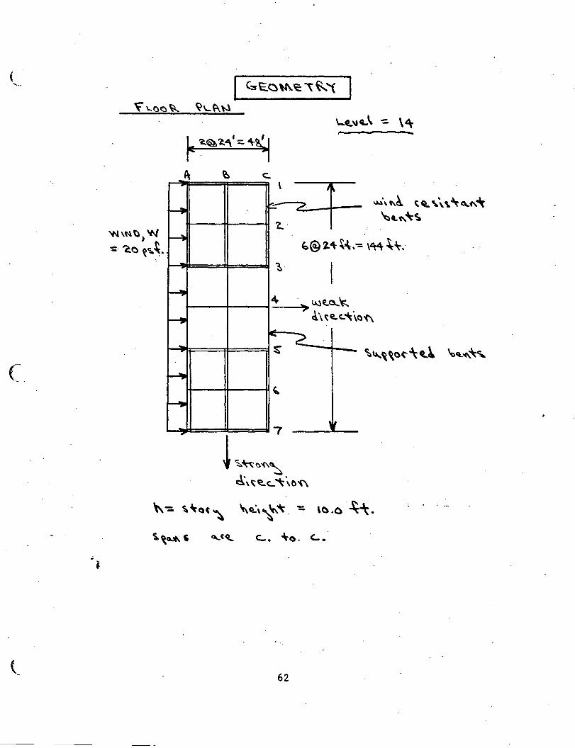
( ..... I C::sE..o\1\~ ~ ~ '(
~'-C~~ ~\..~W
'IN\\'\~) w -=· 'C. a ~~ ~.
~< ~Q~~·=~~
1\ ~ c:. \
~ r:::-
1.· r--4
~
~ 4
I-' L .... ....
... ~
~ ~
~
~ 7
62
J" /
~®~4\-~.
r
. '> ~E!..3.-'t:... ~\~li!..(..~\o
~ -
'~
-
~\t\~ tca. ~\\. ~o_ .. ,,~ ~CL~\-CJ.
' '
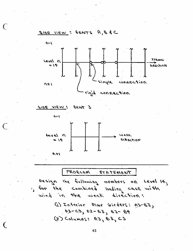
(
?~C)~Lctf\ . ~\ ~ '"~+J\~"-l'
~n ... c.N~ ., ~\~ C:.."''t\0 t.\
\:)(l.~\~<\ \\..~ ~~\\~u.l\'(\~ ~~W\~Q.~~ Oi\ L~\IQ.\ \4~
.:;. ~~ \~~ <:..~~~\i\q__~ \o~\'f\~ c...a...~~ ~\ ~ \.a..:)\~~ \'t\ ~<l ~ ~0...~ ~"~.q_c.. ~\0"'(\ •,
Cl.\ '!:..(\\~~\~(' ~\~~ ~·\(c.\<l~<;.~
\)_}---C..~> ~'2.- ~ ~ ~ ~- ~~ . ) . .
~) <...o\~~t\~~ -~~)~~')C..~
63
C.
Cl') ~~"(\~~~\ . ~\~~-ct.~~\ t\V~~, ~~~-~4\~ c.. ')7/-cC'i ) (..~~c.:. 4
~~ ~\~'(\ ~(' ~4t· ~~\\~\(\~ O....S..~u._'N\~.l \~~\'(\~:
<l) u...~,~(""'~ ~\~\('\ ~""~ ~c\ ~~"''4'\\. ~~0..."\~ \~~~~\ \(',~-t\a<"" ~\~~~ ~'~~q,_'t"-tJ
~<.. ":.. '. (:) "'-/ {..+.
~) U..~\~~~"\'\ ~\~ '\-'{ \~ ..... ,~c\ Ul~t \:-.\'(\~ ~"G.N\'~
\~~\) ~~~~~~~\ ~\('6..ct.~~ \ ~\-= \,~ ~/~~.
~~\.'-~ \~"~ \oa...~ ~) ~~\ \a'-.~~)
~ '<" ~ \ ~ ""\-().. ~ "\. c_o\u...'M.~ ~'lA..r
~""c....
~ ~ ~ ""-'4'4\. ~ (-b. "'::\ '='
\.~ J '-\. \"' .
64
0....~\,.o._\) ''-l\l...c..'-.~ ~..a...} ~\'Et,\(Q~\:,"~}
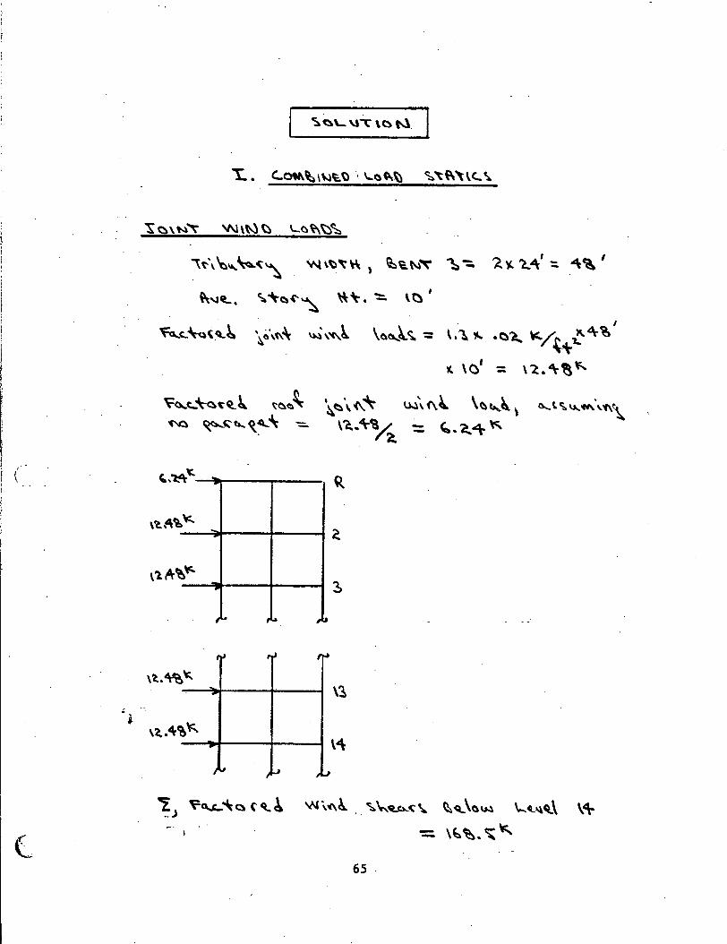
~~\~""t' 'N\N~ '-~~~~
\t-\~"'~'t~ W\~'"~) ~'a~~ ~-:. ~~ "L41
:. "\~I
~'-lCL. ~ "\-()"'~ \\\-. "!:::. \t) I
\~CJ..,)..~: \.~"'" ·0~ ~/"""'-t~~ I
~ \C' = \'2.~~\;.
~a..~~~~~ ~~~ 'C".Q ~~ta...C{~\ -
'~~\.(\~ ~-..(\~ \~e,..~ \ \'(. .. 4\-~ : '-·a.~"
(
't;.
\'10. -
~~ ,L.o ... ~.
,,
\~
65 .
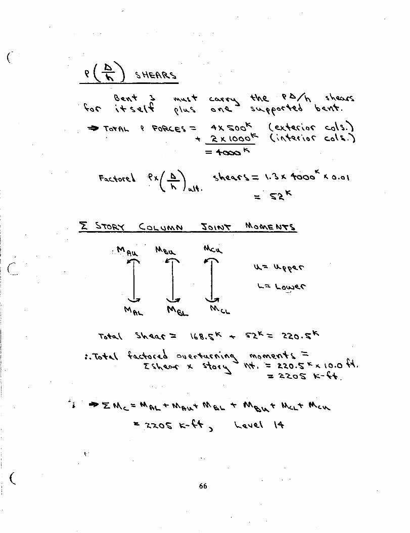
(
(
(_
c..c...~~~ ~'l . ~ h/~ '\~~ ~'C\~ ~~~~~~-"'rt.~ ~~'1\\-.
~ t;:~~C..~\ ': 4 ~ ~()_<::)" -It ~ )(. lOOO \<:...
=~"
l ~\ct.< \a("· c_a\ \\ <.. ~(\\q_~\a' c:.o\ \. .)
\a~\ ~~ .. Cl.~~ ':: \~ \. ~ '*' ~ 'S"l,. ~ -: C."ao. ~"
:.\~-\-"\ ~<l...t.\at..._~ o"ct<-~~t\,~~ ~aM.~i\'\\, -=. !:~"'":.~ 'f... ~~:\()(~ '<\"". ·-= !..1.0.~ ~ )(. \0.0 ~.
': ~~0~ "-~'\-.
\ .
66
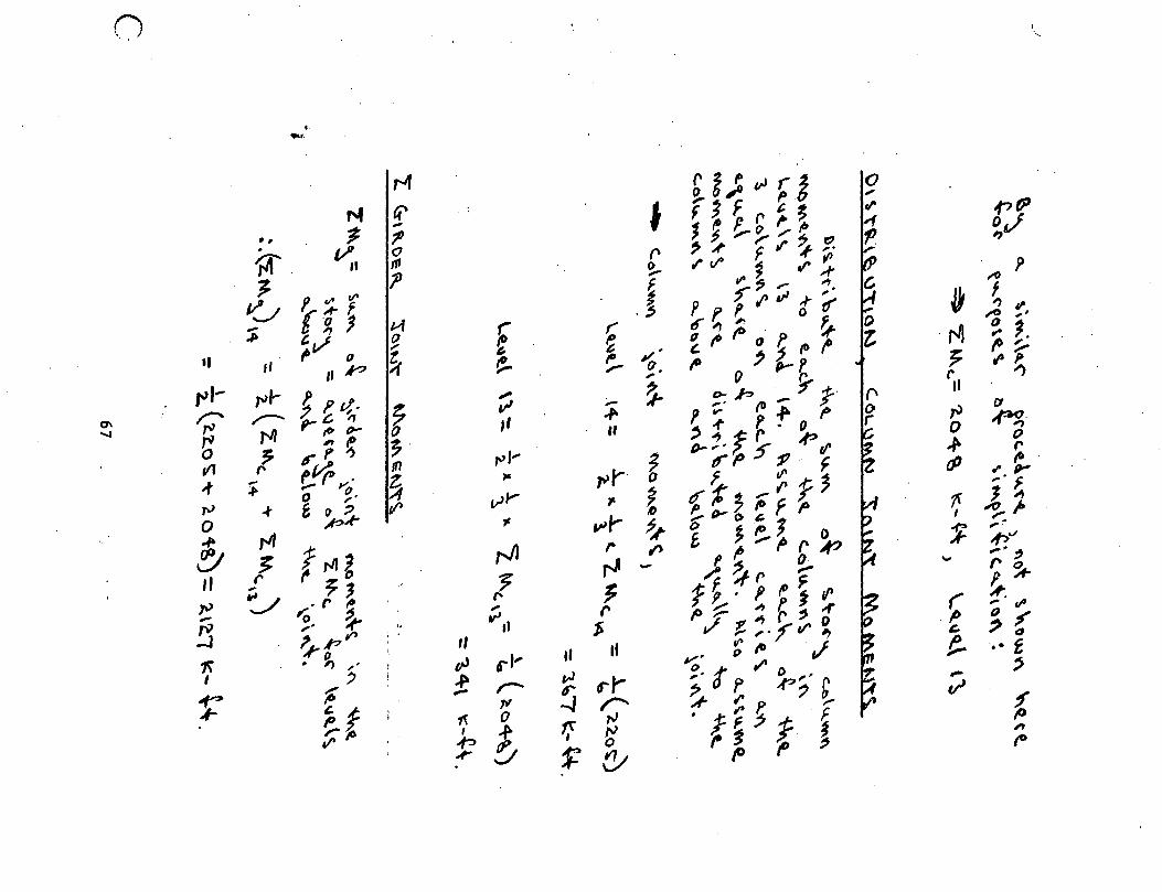
() I ·, .
.. -· r-4 ~i;'-"ri 0 ,
"' (? I 'j F ~· rl' .pfP
-; .... ~ ,,..,.~ .,., •• ? '~.,-(),.I' o,j . (/ 0 " '~ F'"~~ ~
, ~. II "' 1- ?
~ I"VO ~ .r~ ;0 p f_ .,. , ,... "'·
0 ~~f .! Prf~'"'t';r ~ f
·o J t-1
..., ,-
- ~ ;10 ,,
~ &. , (" tf" ,., , ;,
,.v 0
() ~ , ~~,oo·f~~ ·~ ~ 1. ,. •• ~
~ fO~ ,, ,, ../'? ~ I"~ to ~'jp_ 7 ,.... . P- (l~
"'' .... J'1,.... ~ p ~-,. () ~ r
,. -- ~ ~ .b ..... y ;-· II
0\ ~ ,--.. c. "' ff v' ..,. , ... (D.,. ~ C1
....... "" ,. If» I>-
,, II ,_,. ~-0 ~ ~·
~ 7 p ~ ~· 0
IJ- 'J. f. 5 .p tl' _,. 0
V1 " r~ tn "''" ("
~ trl' 17·· f tP ~
..,. ~ t. (" y;' z.. )& ~r· o ,.. "' "' (J'"
rJ ;f> 0 ~- v,.... .,. ~ trt';-"f~ ;· ~
-+ & ~~ tf> ~
0 ~ ,... !> ':,. II-' 0 ~ f p I ~~-
~ rJI ,., ~ ~ ~1>1 0 11 ,.
t:l J f,.ng "" ,. ., £ I' ,... ~ r A'?
_pv
rJ - }. ~r ~ "" ,.:1
II ;, 71 .' 1 ~~
"' 'J .r fi
~ f~·fP~,p ~ , .~ - '0 'J .r,, r P~ ,e.~, ,. 1/'
!:3 ,. ~ "
$ ._~,~r o 11 I' ?. p, ' ' ,, ,..,.?V'#) &,. ~ tJ
',/'o ' !! 1\ . , ,. vJ 6'" ,, al II ,., ~ to ,1 ..• f
I ' i ..f' ,J ~- t ,. t> ' % ,- tr r r ~ p ,p ;· b -
~ - ,r
~t ,., -J r- A- ~ P. - t ; ~ 0
I ~ 1( ~ .,.,.jf ~ V' ?~
,
j ~ (y ,. ~ I' ~ fO
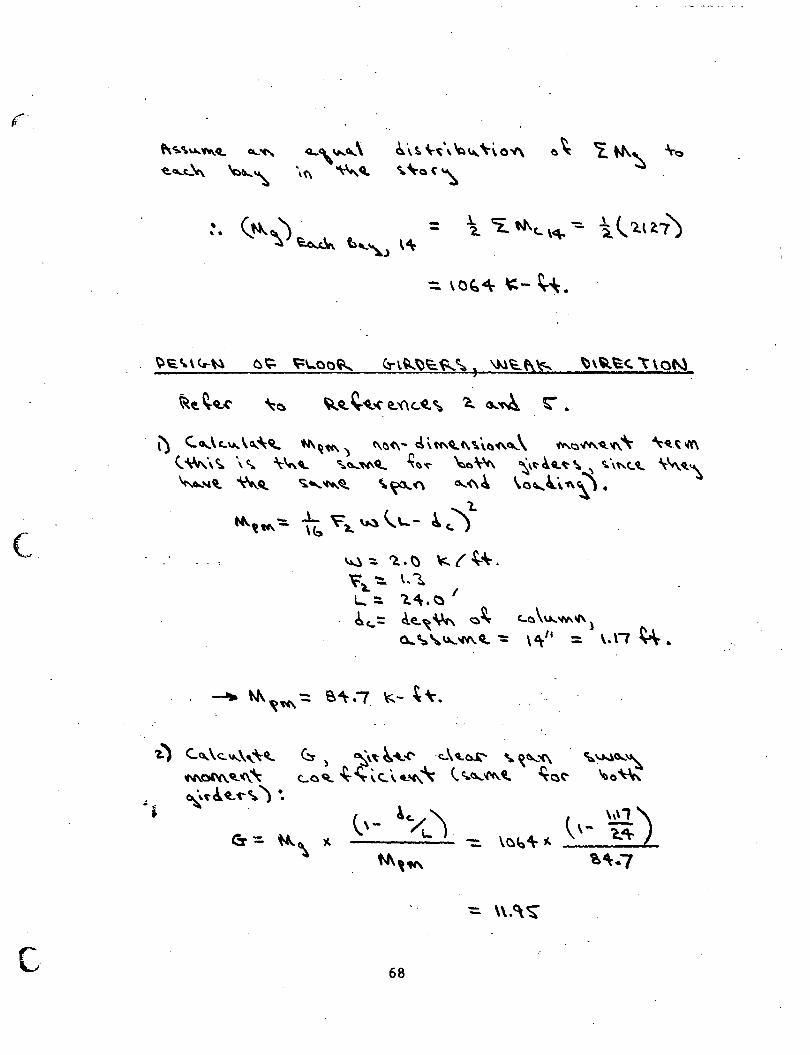
(_
c
~·\S. '\-~\ ~~ '"'0~ ~~Q(~
l) C.o...\c..u..\~\~ 'N\Qtc\) t\M\"' cl\~q_,f\\.\~(\,\ ~~""'-~~~ '\._~It(\ <.:\'.,,\ ~ \c.,. \-~'- ~~,.,._Q.... ~~~ ~\1c\ ~,~ ~Q..~ ~ ' c:.\"t.~ \""-~'\ ~~ ~Cl Ci.'""'-El \~ot'\ ""'-<\~ \.o,l\ 1\\\.
~,w...-::. i6 ~~ ~ \.\...- 4 c..) "l..
~) C..~\<:.."'''""4l.. N\ol'4\. ~ (\ '\
~'"~~'("'~) ~ "t.
~ -::. ~ • ~ \c:.. { -\-"- • ~).. ':::.. \. '1
- ~ I L.- ... ~.(:) 6c..:: ~~,~ ~~ <-o \u..W\11\ l
0... ~ 'U....'"'-0.. ":: \ 6r'' = \. \t ~.
(!f ) ~~ ~~.(" ·c:..\~~ ~ ~\\...'<\ ~~0...~ C..O~ ~~\<:.\~~ (..C.o...'f'C\.~ ~Ot' ~a'"'
68
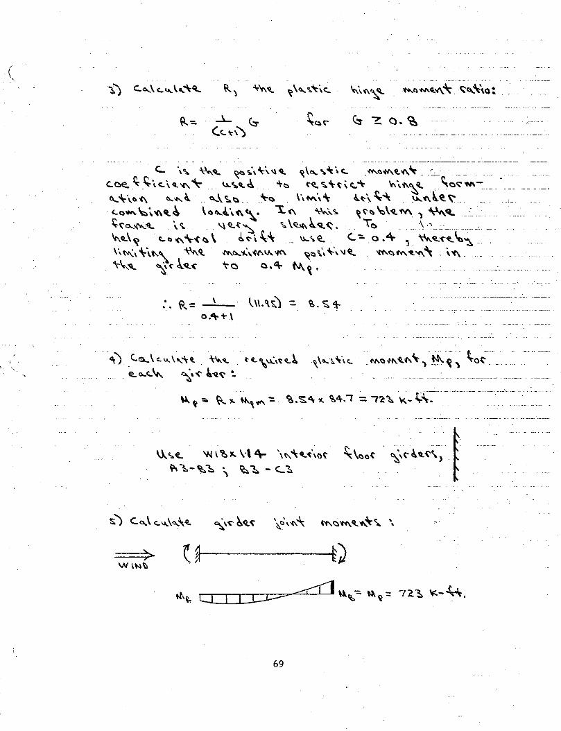
(
. c... \c;,. ~~ ~1::)~\~\."<Q. ~,~,~-\" _<M.Ciotl\t."'~--':_:_ ---
C.Cle,~_~i.<..\~"'~ (.t..~~~-- ;.0 ('(l~"'~\t.~ ~\f\\~ _,_,()~W\~--- --------
~~\.«)(\ ll..."'-~- .. ~\~~-- ~~ . \\M\"' lt-\""\ . ~'C\l~~-- ····-. c...a~~\"'~~ \a~~\'C\\,• '"!.<'\ ~\~ ~t'~ ~\~M. 1 ~'- __ ·:_ ...
~~o...~~ . \' '-\ <t.-t~ "':. \~ ~Q..~. _ To _ ... \ .... ________ ·-·----·- _ _ ... . ... ~~\~ t.C)"''--t~\. ~~\.t.~ ___ 1.)..\Cit_ (.-:._o."\- 'L~<Cl.'f"~~~---· \\ ~\ '-\t..' ~Q, ~()..~" f-1\V... \(('\ ~a\\'\-'\ \1 ~ '«'~ ~ ~ ~" . \ 'f\ - - - . .. - - - ·--. .
\-\,__~ ~-(' .k.~~ ~0 0 .(\. N\. ~ . -.... ··- .... : ....... -· ·--------·--· --.
:. R= ----'-
·i ' 4;) C.~\c.u..\~"\~ ~~ u ... \1..('~~~ ~o...<..\c... ~'~ ~-q_~ ~
\!...,. ._ "" 1'~ .... \-\ + \"'It ........ t !\, "'· t ~' (" I. .. ~~) t ~1::.-~1:. ) ~~- '-~ f
69
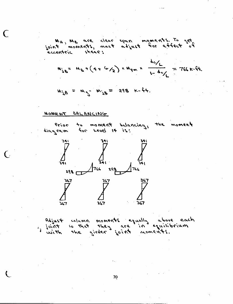
c
(~
l.
~ ~ ) No..t:, C...:( e._ c..\~c::...('
~o\~ "t ""'o""'~"'~~, ""'-~\. ~ Q.U...oQ.~~\.c:.. \"'~~ ...
"S.~~ ...._c:)"'q_"'-~\.. To ~f!!t ~~\.~~'\ ~~t ~~'COl(,.~ 0~
. lt. 0 ~~ "'"t' ~~\.. ~~<...\t.l<.:r-
~('\a~ ~~ ~aN\.~:C\~ ~~\Q...'C\<..\.+..~ \ ~"- 'N\.(,)'CII\.~ ..... \
~\c...~~'"' ~0~ \....~"~ \4\- \~ •. ~~\ 'l'r\ ~+\
l ! ! '14\-\ ~ 3W ~ ~~ 1.'' ?~t. 1.(\\ r~b
~~7 'lC.."7 ~~?
l l l ~b7 1.~7 . ~C:,?
~~~""~~ .; \c.),.(\~
c.. e. \~1M."'- t'4\ a M. ~ '4\ ".r ~ «..\~~\\'\ ~~~~'L • e..o...c..~
• W\""' \.o ""'-~~ '""'~ '\
"""""Q.. ~' ~ 4-4...<:'
~~~ \of\ 0..\ ""- \\, ~('\~ ~ \. () \ ""\ N>,. (,) 'M. <t "'-\- \ •
70
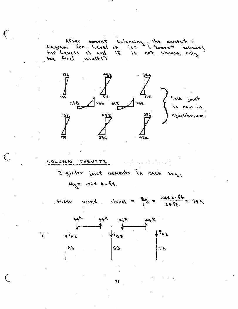
C.~
.,; '
J
(_
~~'0..< t-1\c)~~i\~ !\,~(''~ ~~(" '-"-~'-\ ~o(' \...Cl.-.u .. \\. \ ~ a..~ ~~ ~\(\~' ~~~\~\.'\
~cs...''"<..:\C\~, ~'Cl.. .... ()1'1\.ct~\ ,, \'\- \ ~ ·. {.. '0-~-t\"' ~cs...\~,+.,~ \ ~ \ ~ (\()~ . ~ ~0"'-)'(\) ~(\\~
.. -
~~ ~c\+..~
\~ (\~~ \'f\
~\ u.:S,'b<-\ ~"' •
"t ~,t'~4L~ \~\(\'\- tc\~ft.ct'C\~'\. \" ~o...t....~ \.,~ \
"'-~-:: \Ob'\- ~- ~.
~\,.l~ \.~...)'\,(\~ ""'""""~ ~-: \«l~«\- \:.-~
"'"" ~ - -- 2."\- ~. --'.· l.
~~ ~~ 'tJ\~ ~~
~ 1 . ~ 1 ~~\\1. ~~~~ .~C.'\a
~"' ~~ c.~
71
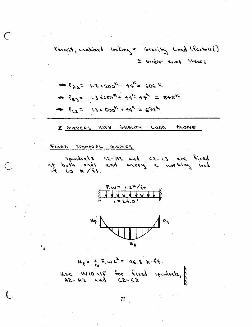
c
~ . i
\~~~t~,:\) c:..o~'a\f\oCl~ \6,\\'f\~:: . ~t~\l\~ '-ott...~ \~~~\o\t.ll
~ ~\(~~ \N\'C'.~ ~"'t.~ ~
":1!111> ~ "~-= '· ~ -..'So~- dr~= ~oro "
.,... ~~ ~ ~ v~ ~~~o "- + "t4~ ~~~ ::. ~"\-s"
_.. ~c.."!:.-= \.~"' !;oo'c¢.. ~ ~" -=. ~~'\-"
~~)..~~\~ ~\- ~o\"' ~('..~~ ~~ \.~ '.=. I~\.
~l...- ~~ ~'1\~ c.~- <.~ 0...(~ ~·,~ct.!. 0-'N~ C..~~~"\ G... WQ~ "-\'«\~ \a-.,~
~D ":: .l_ i\ W \_'1., ': '\~, ~ ~-~'\- • ' . \b
~~.q_ '1/\J \0 ~\~ ~()~ '""~~~ ~~"'~(ct.\~) ~ \\~- ~~ '-11\.4 c::...~- C..1:. ~
72
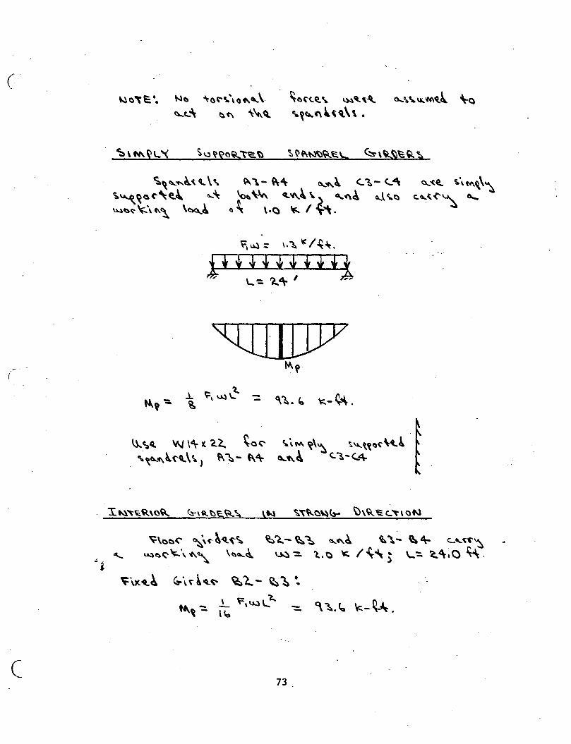
c-
(
.:.
c
~a~~', ~a '\o~\.\o._,\ ~aC'C..~\ \.)..\'-~"'- o....~~u..~~l \-a ~t_ "\ e.(\ '\~ ~ '-~~~,~~\\.
~''"'~'( ~ \\ ~ "\- ~"" ~'f\.~ <.:~- <..4\ c:.~~~("~t,~ .... \- ~~ ~'4\,~\} "~4 ~.l~Cl ~~~~\C\~ \~4 a~ \·~ ~ I~'"\.
~-~.
~'{'!., 'io.\ M.\\~ C.~(.('~ 0.....
~\oo<' ~\t"~-4t'('~ ~'}..-~~ '"'~ ~'\- ~+ C...'-~f'~ -.... u.l~~ \;..\ 'C\.~ \~a....cl ~-::.. 'L o ~ I~~ ) \....-=:. ~ 4\; 0 ~ .
73
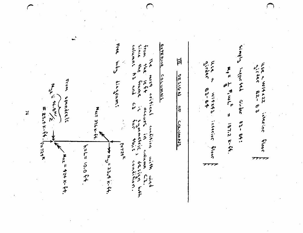
r
......, ~
..(J
.... 1 0
., --
"" ~ 0 ,
.I
{1
r tl' -P 0 -· , -? 0
~ ~ ;
- ~ f 1- t ':1' p I'
p- v' 1 ,, r- 0 , fO "'
"' ~ ~ .(?k
t.~ 1 , I>'~~ II • 1> ~ I' • "' .... 7 ,. ~-'~,., # •• (' -1" • "'" I' ]! "' • . -. _,. ,.. -;:; . 11 "' o r 1< r p ' ~ • r ,.. _, t r ~ r11 ~
~ ,,.. J
.,.. t< 0 - . ' ' {' ,.; I' ' ..,-- :1= ~ • ~- ~ . ~ -·'
;j '"\_ 7 !~ -t ~ ~ ? .#- ,, ~ ~- ... --1f 'F ,... ~ o, ,. D ~ ~ ~ ~
,.. '' ~ !t r ,, , ~ t' v !).. _,. ~ -,, r F E rJ 0 "' 0 ~ ~ ,· .,. "' 7"'; '1 f :,. t: :::
• I. ~,/; (' :r f p Vi;. . :t ~ ·" - .tr /)-'
~ ~
~
~ '(I
r ~ ~ z (/I
~~ F , ,.. r,. ~ p
fJJ vl£
I -tJ~
~~ tr
7 .,. (0 ~ -· 0 ....,
·-"' -0 0 ..,
~ #0 ,,
,pi' "f1 ,.
£ ,...t>
II
-tP ..J • f'J
tr I
~
" ,,
' -~
" ol' f ~ ~
~ r
~ , ...
r tP
"" I
$ ..
r {~ ';p " £ -,.,. ,.., ~
·~ tf' qJ ,.
!' ,,
" ~
f D ,
(")
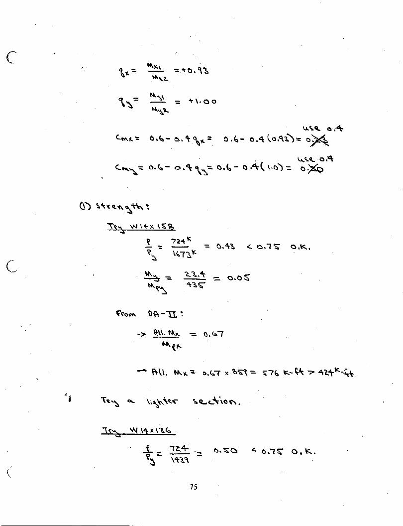
c
C.
_,;.
- ~ \. 0 0
u..~~ o·.~
<..~~-:: (:),~- ~. ~-\~::: 0. ~- o ."\ \o.<\l.)= eM V...'~ -a."<\
c......,~':::. o.~- o. <\ \~-:. o.~- o .4r~ \.C))':::. o :)(Q
''";:s '1-l \+)C.\~%
~ 724~ - - - - 0."\~ <. o.('$; o,\<.., \>~- \~T~~
o.os
i \ot~ ~ \\~"' ~'('" ~~'-~\a"'.
\("~ 'N \1 ~ \1..~
j_ _ i'a4 _ o. ~~ ' o.,~ o. \=:.... ~~- \'\-~~ -
75
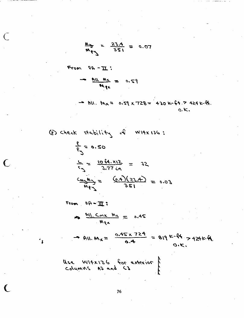
c
• •
~ - 21..4\ - ~-01 -1'1\t~ 1-.S\
'rt-atc'\ ~~ -"'I.. ..
-- ~\\. ~~ - (). ~·~ -~,~
--. ~\\. ~~ ~ o.~ ~ l'a~-= 4r1.o ~ ... ~, .? ~~"\ ~-4\.
o.~ ..
~) C..~'tc.." ~"'~~\ \', '\-'\ ()~ w \"\~ \~<a ~
t -: ~. SCl ~
c. .... ~"~ -:::. (t,.~)( ~~.+) - ~.o~ -~~~ 1>S\
'fta~ . ~~ -·:m. ~ .. ~\\. <..4'1'\.'J'.. \11\le.,. ().4~ -t4\ Q. JC.
~.4\:~ )(..I C.4 ~l\ ~-~- ? ~1.4~,~-~ ~\\. "")(. ~ -~.4
o.~,
\l...~-Q.. W\<\-lC. \~ ~ ~~~ Q.x.~\~t- ~ C:..()\~'t4\'l\.~ f\~ 0...'1\~ "'"\ . f
76
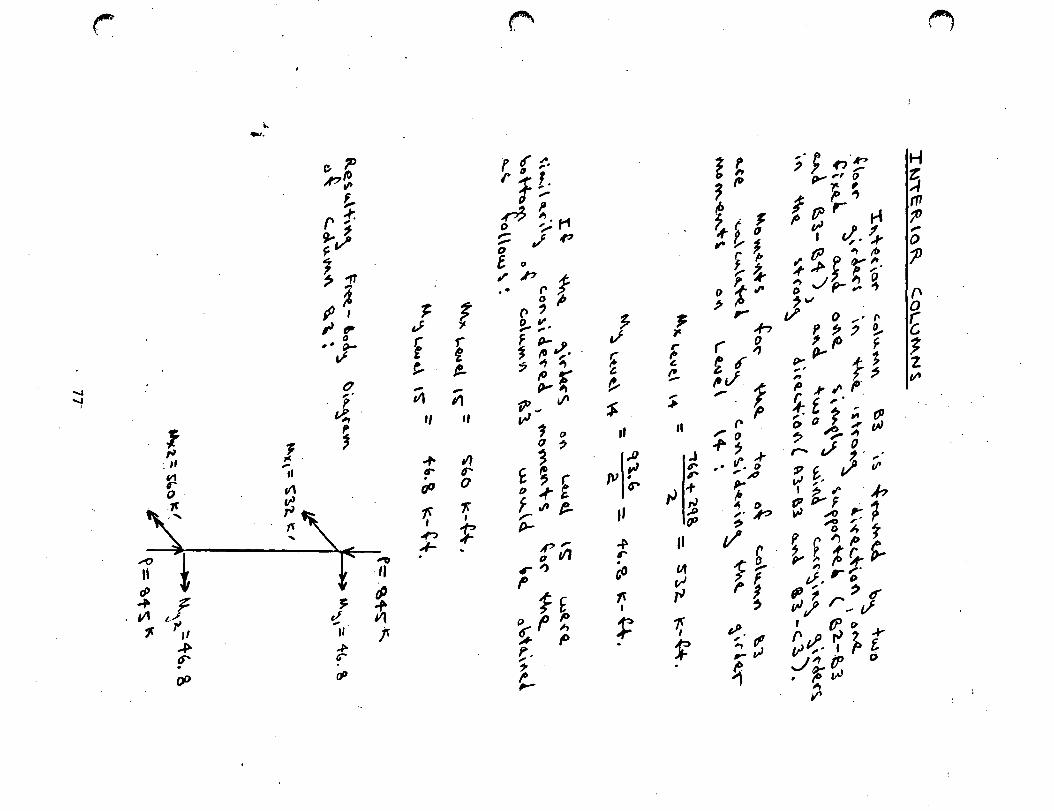
....., .....,
I
~
t. -· ~: PI!>
!.. r1 ~J ~ 1f
~· /lt ~fl'
0 ,, ~ v
0 ,.
' ~ 1 !
; ~
: ,, ... tl
~ V\ .
~ ~, .. " ! --r ; $ ~ J ~ V1 t.; .. II f ~ ,, ~
~ (i IF" . • d' fP
~ ,.;
f t, -tl1 ,,
..,. tr . all
1[
~ .
f f e. -V1 ,,
"' 6"' 0
-,: ' 1f
f"
I' ~ -:-r1~
' ~ ,,.,... o ~ r' ~ .I , 0 e. 0
II' p ,.f; .. ~ ~ r ., ~ ~-F P- o ~ fO ~· ., ., ...,
:..r 'P., II'
,., ' ~ 0 .,
~ t ; (" 0 ..,. ~
'"'e. ,... P-
P'" 11 til
r'> f
f£ () f p 6': h , p t· ~ ,_
7 v r; ~
t-1-,,
~I~ ,, ~ r . G'J f{ I
~
~ 7'
~ c. ~ , .,.
II
.J 11" r
L} I+ ,., ~ fP
II
ell v rJ
t; f
E ~ ~ (0
!J 1 ~ f a ,-v~
r P !--~ () t .,.
~,. ,.., 0 r , r ,
to,./ '[ ., r
ro _,.~~ • If". I> • , ,t1
~ ~ 0 . ,. p ~
t/ r -;g.. ,.~
' tJ>. ~ tl' _v~
~
~·; .,·~ y ,, ()
I ~; p ~ ,- ...
I c/,. ~ tP "' t1>
~ ~ ~ ¥~. ~ Jp- ~ ~ ,..,
1/ 0 •(' ~f?'3~ P r
'!:,.. -t; , f ~ p ; "' p· ~f,.·~· c,a,l~~
. ~ 'r 3 r-- v '-. ,· :P f. ~ II' "' , . I~..- J? ~ p.-.1 ,;. 1
,0 ,. r p ~ ~ t ~~%~~
. ' ,. ,.. v, D , , ~
vJ} r_ f I fP_o
""rJ~ ..... cr ,. ' r t J"'IP o . ro ,_..,
'1ft V'
H
~ "' 1' ,.. 0 tJ
(\ 0
f 1 z II'
~
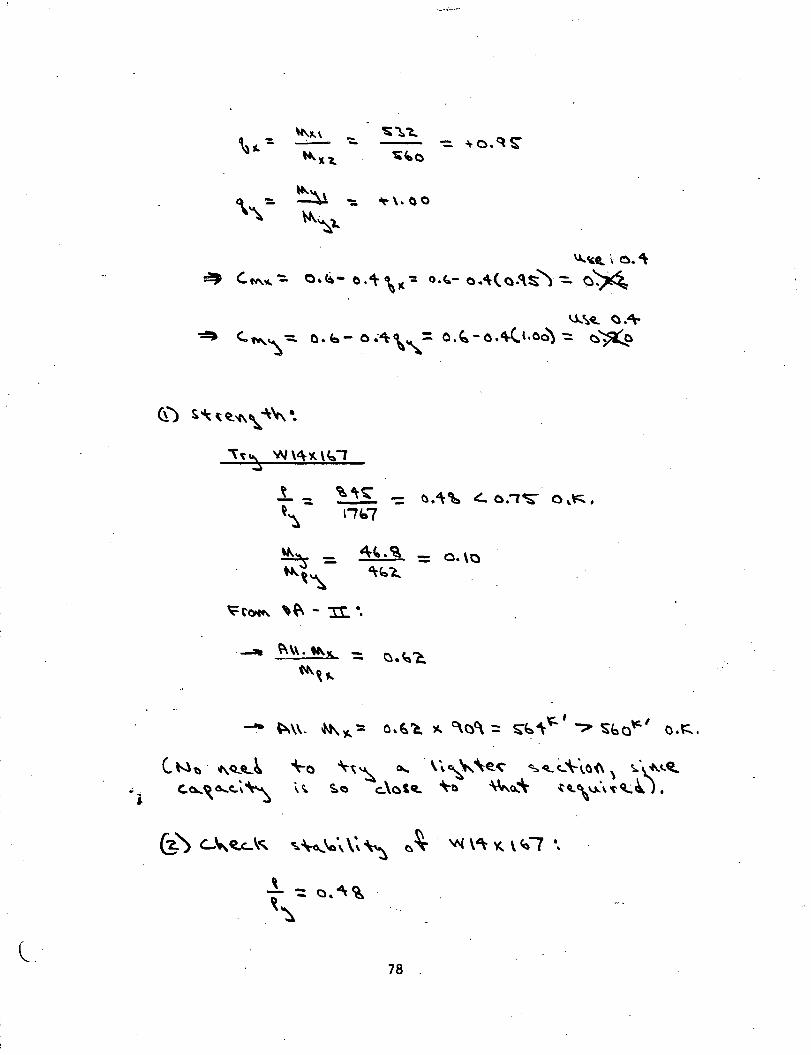
;
I J c. '
\t.." \ - ~~'l.. ~ - - -\-0.<\~
.... ~ 'l. ~-0
~\l ":. ~\.()0
~~l.
"'-~4l i- o. '\ ~ '-"'-~e.-:. o.~- o .'\- \K-: o.<..- o.-\( a.<\~)-::.. ~~
IJ...\~ () .4\~ <:..""~ ~ o. b- o .-~\,:. o.~- o.4(l.oo) ':: ~~
\~~ W\4~\~1
.1. ":. ~ -= ~.'\~ ~ 0.'1~ 0 '"' ~~ lifo?
~ = "'""·~ = o.\o ..... ~~ ~~~
~"~ ~~ - 'It.·.
c. t-l1) ""<t.4L ~ ~~,a...c..~~
(3.) '-~ 4itc.. \~ ~~\a\\~~ ~ ~ 'N \ ~ ~ \ Co-, •,
\ ~ - o.~~ -~
78 -
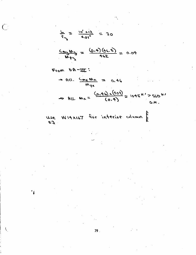
·-
\... ---~~
- "lo
_ o.o~
~ f\-\\.
,.,.,.. ~ \\.
\J...~~ 'N \1\ )..\b'7 ~at- \i\\~'t'\\\~ ~o\'A..'M.\f\ ~ ~~. £
79.

9. FIGURES
80
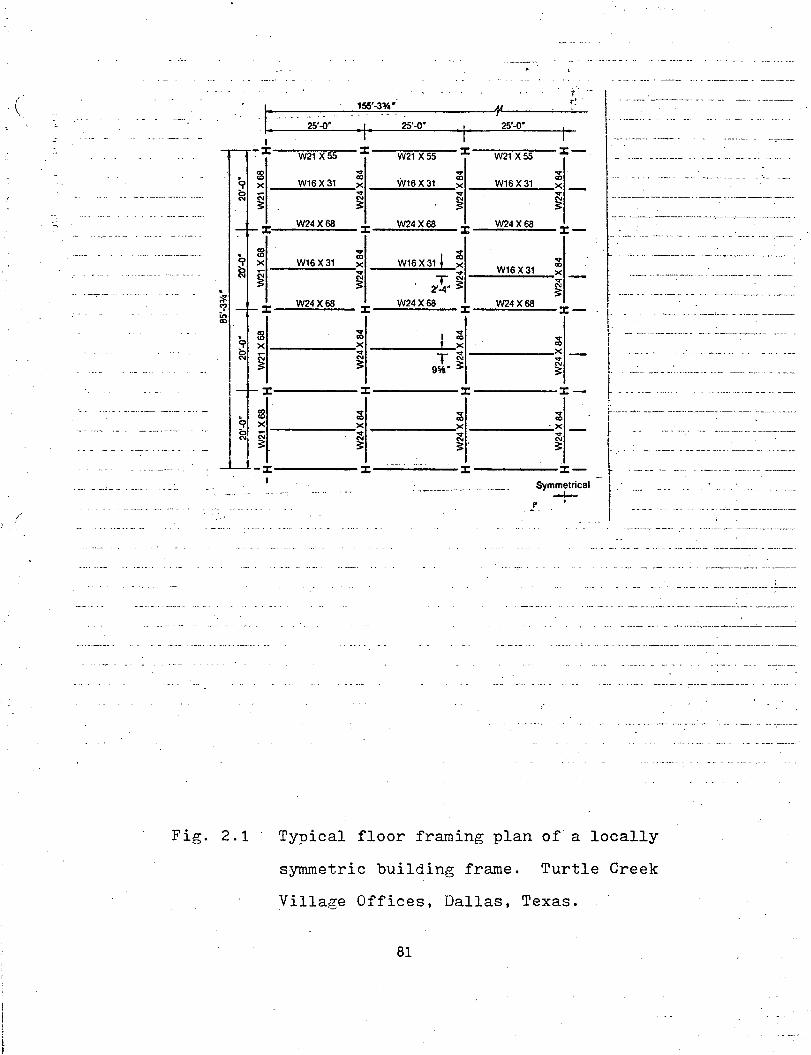
. ~ <? i:n CD
~ "'
9 g
t' ... 155'-3~· ·t·! .
~------~~~~----~--~~~--~~-I: -I
-:-X
a>
"' X
<\i ~
X
:2
25'..{1"
W21 X 55
W16 X 31
W24X68
.... CD
25'-0' 25'-0' I'
W21 X 55 X -~w=2,...,.X:-:55,...-- ::c-....
W16X31 CD X
~ _....:;W.:.:1.::,6~X.::,31:..__x _ ....
"' ~ ~ W24X68
X __ W.:.=24:..:X.:.:68:;::...._ ::C _
~ X W16X31 .... "'
W16X31 ~ X
T~ ~~~~~-~ ---~~~- ~ ___ w_,_s_x_3-.1 -:x
~ ~ 2'-4" ~ ~ X W24X68 W24X68 --:.:.:=.::::..-:c-....:.:.;;..:.;.;:.::::..._ X __ _;.;W.;;;.24.;..;X.;..68;.;;...,_::C _
f -::::-···--~~ f· l·
• :2 ~ ~ r 0 ~ l , x ______ x _____ ..~..-x - •
g ~ ~ gi· ~ ------:i - t -~~: --~-~- -_-______ ·-- ---· ---1 x-----x-----x-----x- ~- .. --- --·-· ···-·· ------··---
1 ~~ il-· --i --i .--· ~ r-~---~ ---=--=:= -=--n -x------x------x ------~%- -r . . -- -- --~----= ~-= . XSym~j~ical J ·
Fig. 2.1
I
Typical floor framing plan of a locally
Turtle Creek symmetric building frame.
Village Offices, Dallas, Texas.
81

(
,.,.·
Fig. 2.2
1.0 co X
co -~
W12x16.5
,--------1-------1~
~ ....... -- ... .
~--~L_--1--~: ~:-.. ···---· . I ~-- ·-
: +J ;:::-----~·--~ .. -- :
Floor framing plan of a locally unsymmetric
building frame. One Chemung Canal Plaza
Offices, Elmira, New York.
82
.I
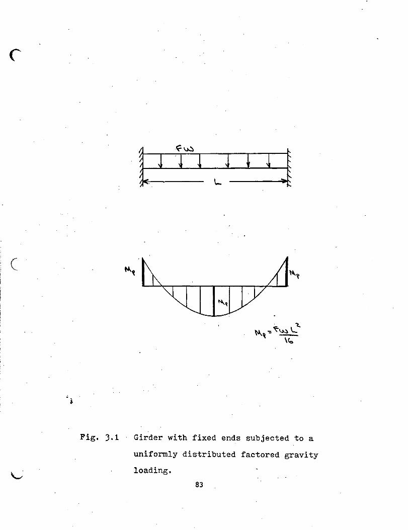
(
Fig. J.l
:
Girder with fixed ends subjected to a
uniformly distributed factored gravity
loading.
83
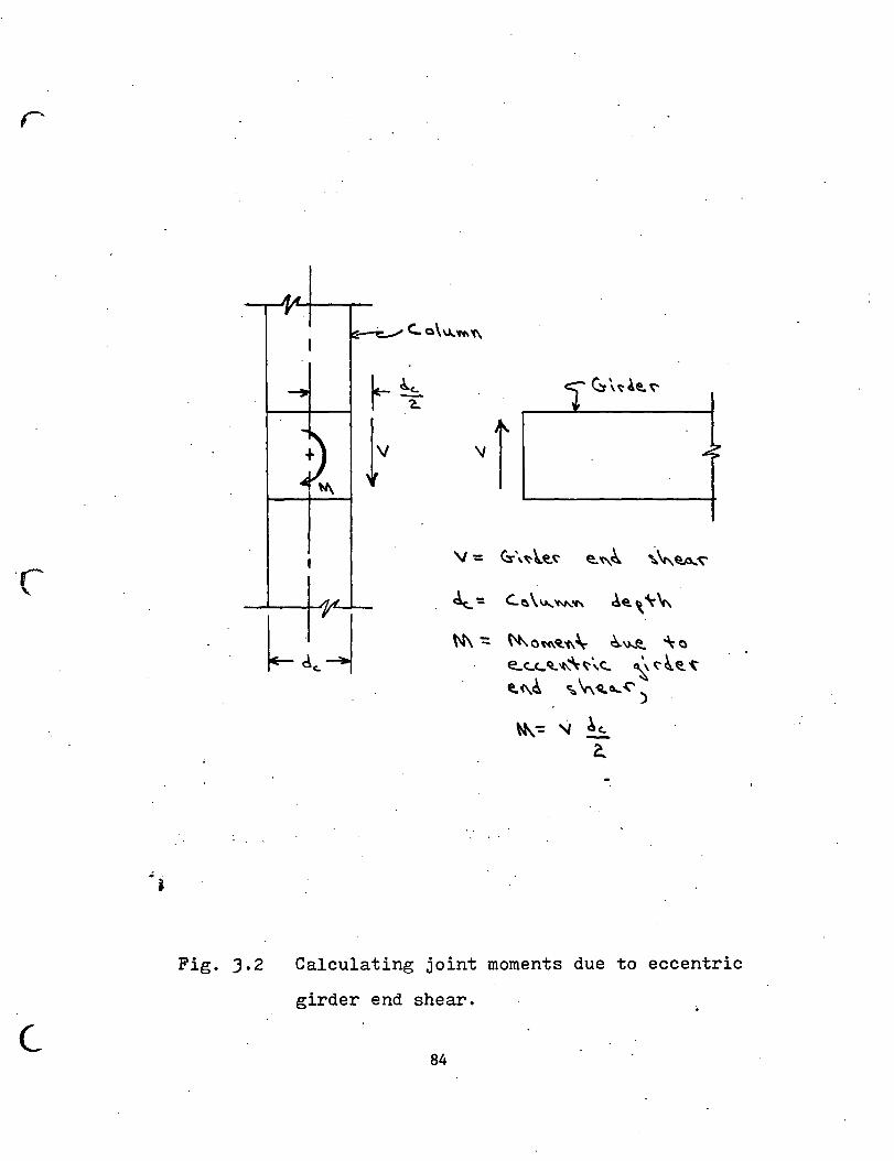
·c-
Fig. ).2
(_
'-: '-~ \ "''N\.'C'\ de. '~ \-.
N\ -:: ~0.-.c\.q_'C\\- ~\)...~ ~ 0
e..~c..Q..'t\'\~':..<:.. ~ ~~~ '("" ~(\~ ~ ~~o...(')
~-= "' h a
Calculating joint moments due to eccentric
girder end shear.
84
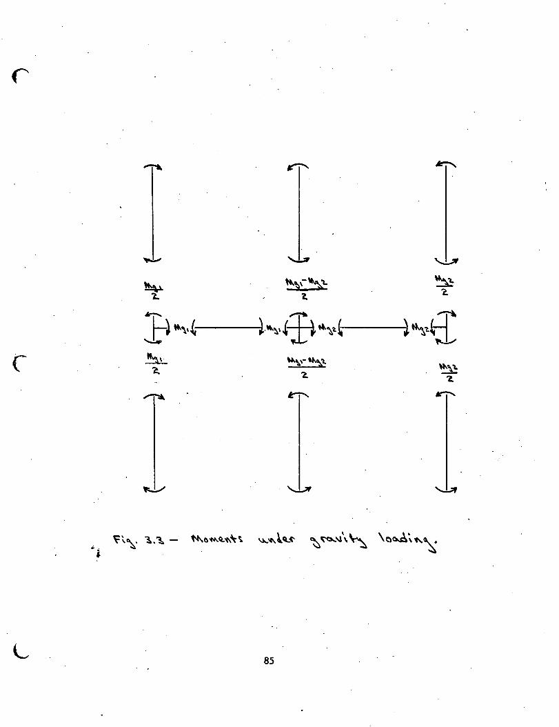
~ '-!..7 '-.,!..;IF
~ t+..t;f''L ~ 1.. 'l. " ~ ~
~~·8: t-) .._,,~ ~~·~fl ";·' .........:...
~ ~,-~'1.
"''" ~ 2. 'Z.
~ ~ ~
L 85
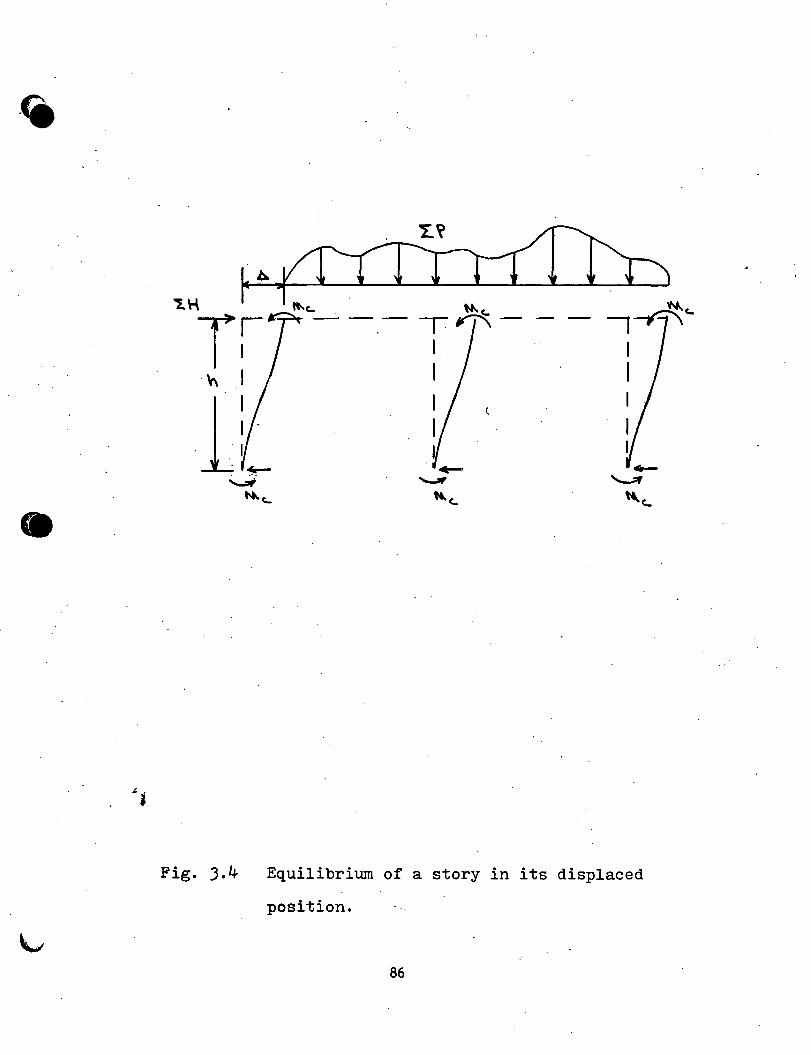
·fit
·~ rb,~
'l.H "'-c.. ~c.. ~c..
Tl -· -.- T rl'\- - - 1-,-,' I I . . I
-~ 1 I . . I
l!_ ..........;;
~c.. ~~
•
Fig. J.4 Equilibrium of a story in its displaced
i . position. '
86
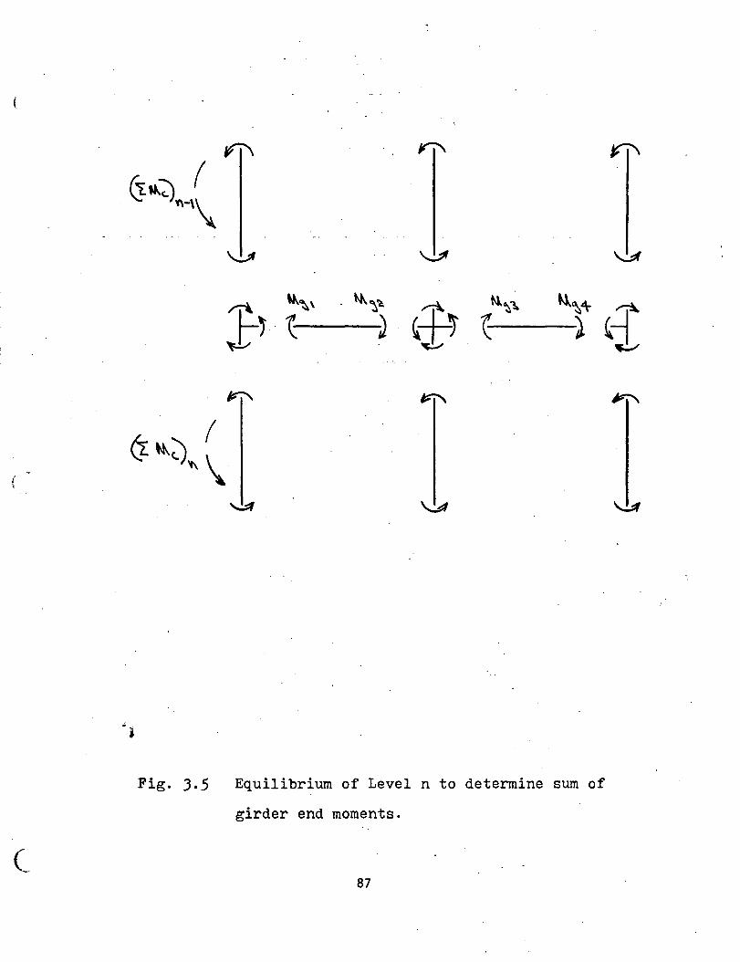
~ Ill\
~~~-0 ( <. '1-\\.
~ \...!:If
~ ~~\ ~~~ ~ ~~~ M.~4 ~ t~ ~ ~ '*~ ~ ) (-j ~ ~ ~
-• Fig. 3.5 Equilibrium of Level n to determine sum of
girder end moments.
( 87
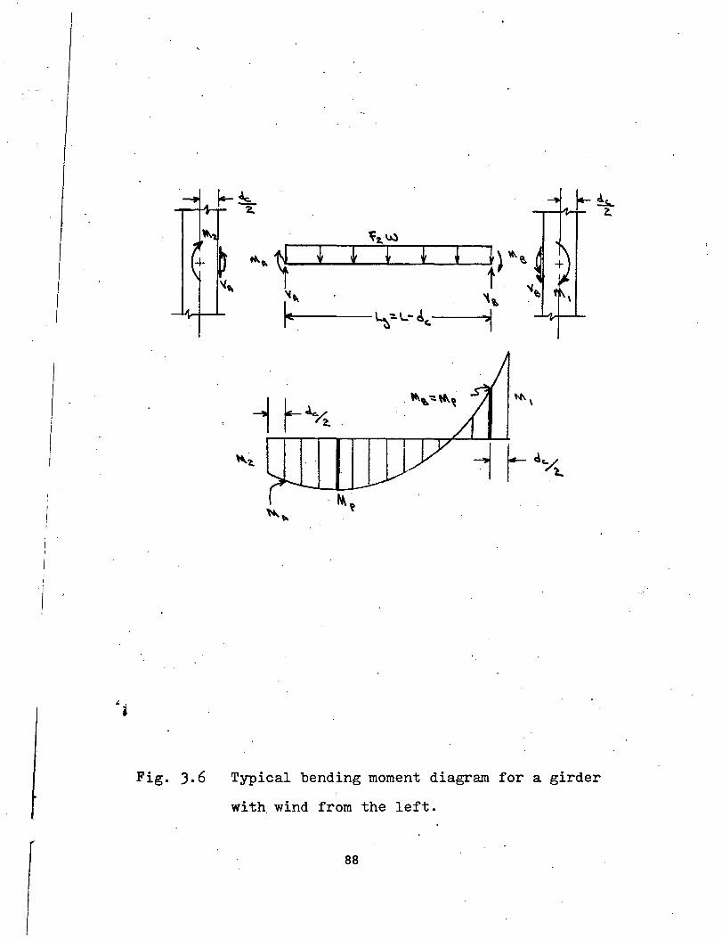
" . i
Fig. ).6 Typical bending moment diagram for a girder
with. wind from the left.
88
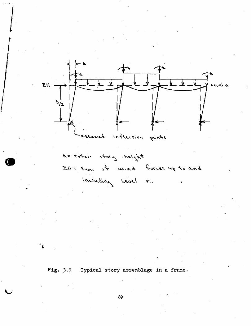
• ~ "= ~c.~,\· ·~.:~o~~ , "'-Q\~"'-.~
'L ~ ': . ~~ 0 ~ . ~· \ "'~ ~c:)~(._oQ. ~ ...,.,, ~c:) 0...."' ~
•
Fig. J.7 Typical story assemblage in a frame.
89
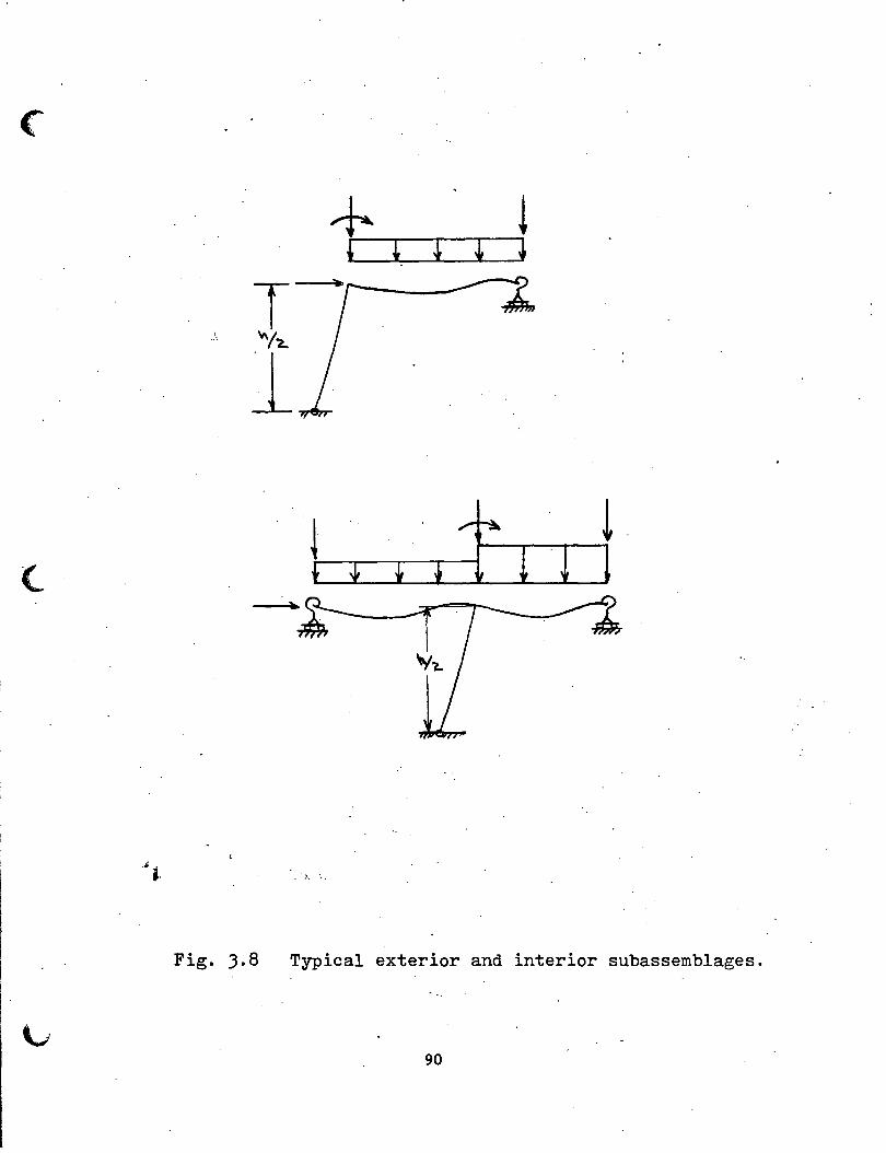
T .. ~ "'!?...
1
(_
)., ·.
Fig. 3.8 Typical exterior and interior subassemblages.
90
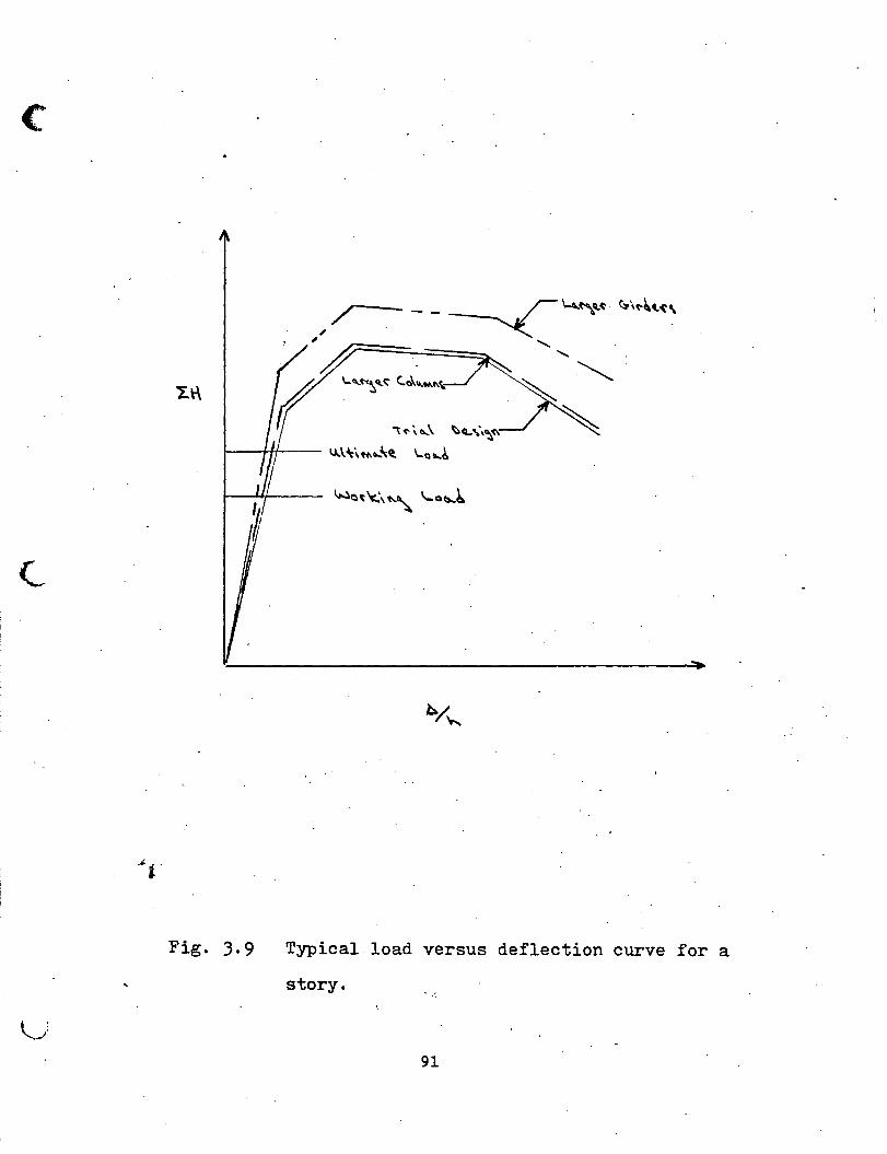
c
, ~ - - ~'-'-~U' (:,\"'~~~\
'~- ',~ (( '-'~~· ~"'-·• ''
~ ('' "'' ~Q.. .. \~~ 1--t-H--- IJ..\~i.~6..-'t. ~Q6..~
Fig. 3.9 Typical load versus deflection curve for a
story.
91
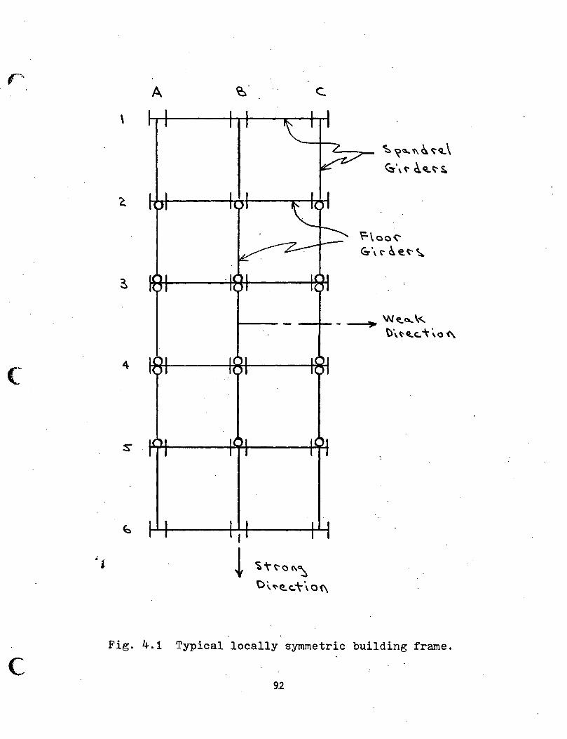
c
c
A
\
4
c.
I
t ~T<:'o"":::, C \ "e..c.:t \ o {\
~ ~~1\~~~\ ~\~ ~Q..~S..
Fig. 4.1 Typical locally symmetric building frame.
9_2
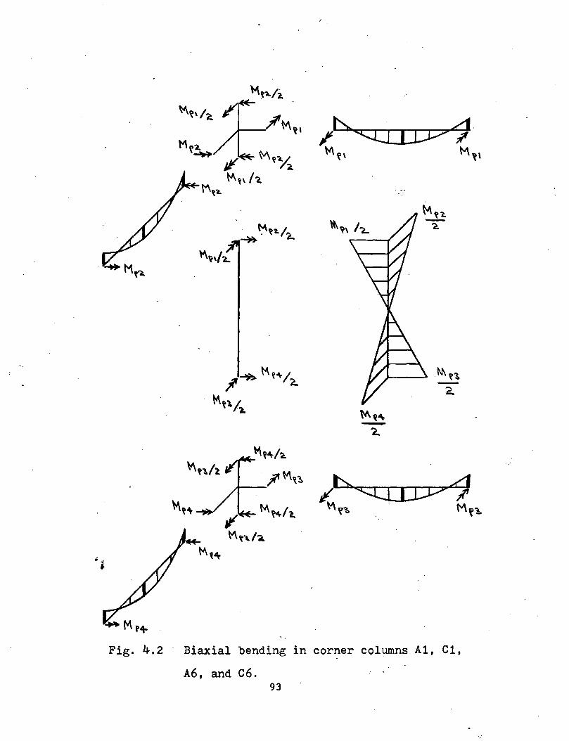
Fig. 4.2 Biaxial bending in cor~er columns Al, Cl,
A6, and C6. 93
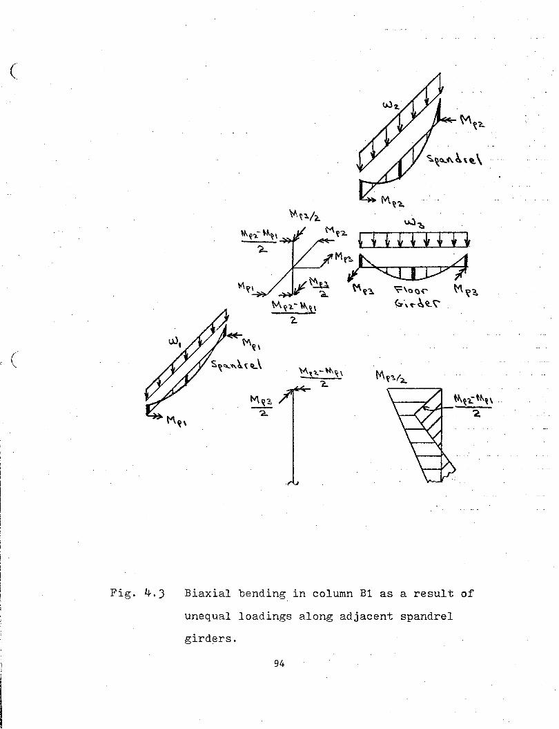
(
( '-
Fig. 4.3 Biaxial bending in column B1 as a result of
unequal loadings along adjacent spandrel
girders.
94
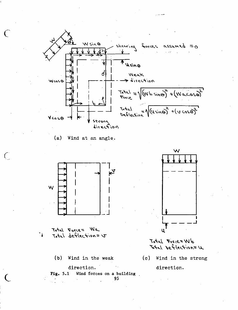
c
. . ,: .. ~
\1\l~~~
-~ c~:,~~c...~·\a(\
w
(a)
~~('<:)'(\~
!.'n'f..c...~ \o-1'\
Wind at an angle ..
-1 ·~ I I I I
~~.....:.....--~-J
\o-\:~\ ~a(L'\.-:; 'N 0...
\o'h .. \ 6e.~\~c... ~'a"':: \l'"
(b) Wind in the weak
direction. Fig. 5.1 Wind forces on a building
95
w
I I ~ ___ ...J
\.\.
\o4.;~\ ~o\L~":.~'-c
~''-' \e.. ~\t.c...\-\~1\-= \l...
(c) Wind in the strong
direction.
i (.
\ ·.
~~ \~~ ~- ~~ -::. ~1... _{ I I I
II 1: 'I:~~a~,')~ ~~, .. i\S. _}
~~\T-~~E.~~-= ~)\ 7 I'
1\
I' I I
~ I 'I I, ' n
n ~\~\JN\~t ~\W~'{
ll '-
] ~\ ~\
I I I I ~
Fig. 5.2 Assumed versus actual sway deflections.
96
/
\_
I ' . '
(a) . Unsymmetric frames-.
(b) Frames with central
cores.
(c) Building obstructed
by other buildings.
(d) Building restrained
along one edge.
-o------. -. -
~~
n r-----~~
[\ [\ [\ \
~------------------~' 1\
Fig. 5.3 Cases in which torsional effects must be
considered. 97
c
~
~~~~~~~~-r~
L-~-t~·-- L
I /El: I
I
W\'--=. ~t.~\~~\i\~ \\t-lt.:t" 'N\Ot4'.t..~\~ 0....\0.:\'C\\~
~\J.lO...~
Fig. ).4 Girder rotation resistance against sway.
98_
Fig. 5.5
.. \_ W\~~
J ~~~\ <;,. ~o.,;~~
"'""~ ~
- \ ~
...--
-
I
I ~~~a(\~ 'f 't)\ "~c..~ \a'<\
Spacing of wind resistant and supported bents·
in the weak and strong directions. 99
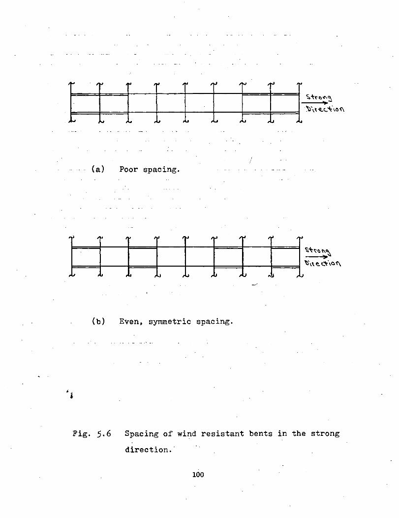
'"" . ~~
"" lrl -~ ;~
·""' ""' ... ,IJ .~ .. ,L.,
(a) Poor spacing.
-~ , .. ~~ ltl , .... I,J
,J f,l ,u ,LJ J..J ,u
(b) Even~ symmetric spacing.
II>J
-~
;J
1"'-l
I !
,r-J
,i.J
trl
.-!J
""
,.l,
I,J
l.J
~~f'e.-t\
·~\~'t.<..:
~~~e.~~ '>
~\\e. ~\0'<\
Fig. 5.6 Spacing of wind resistant bents in the strong
direction.·
100
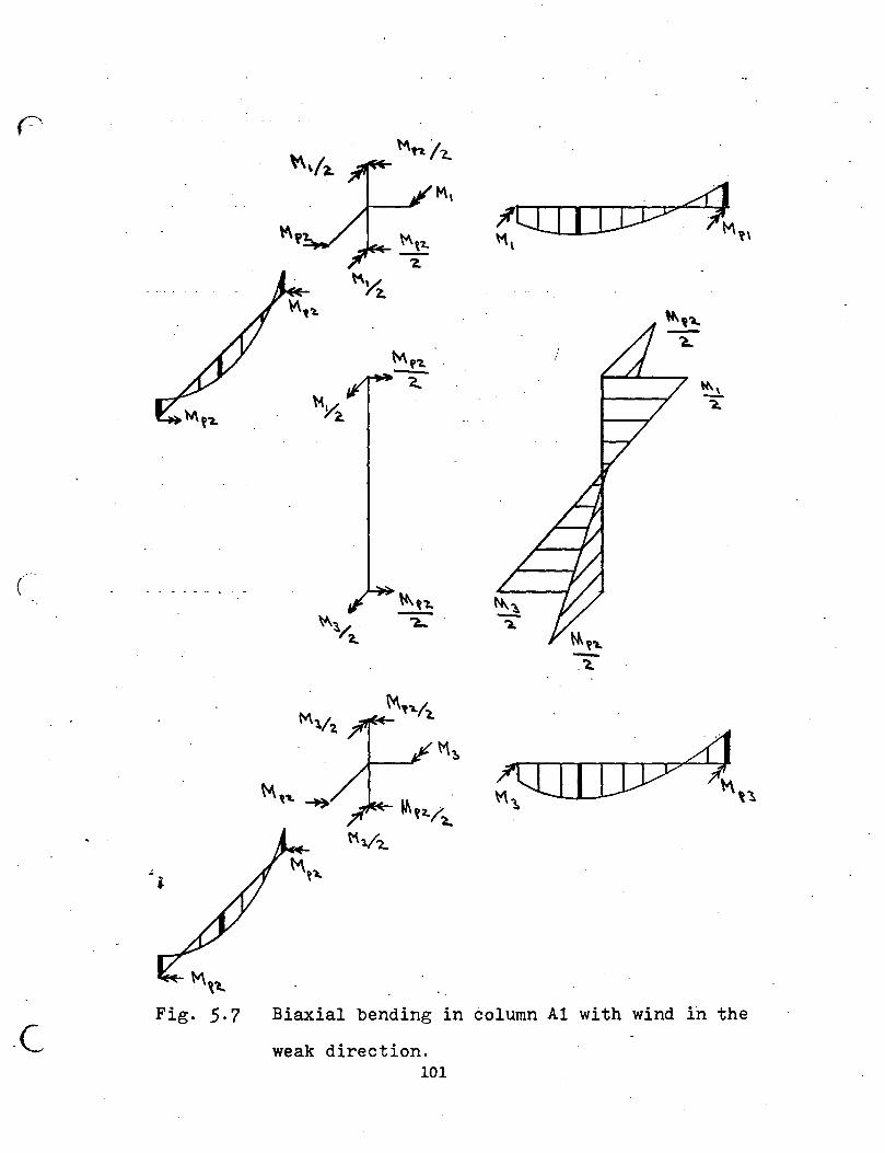
r·
(
.c
.4
M\1..
Fig. 5.7 Biaxial bending in column Al with wind in the
weak direction. 101
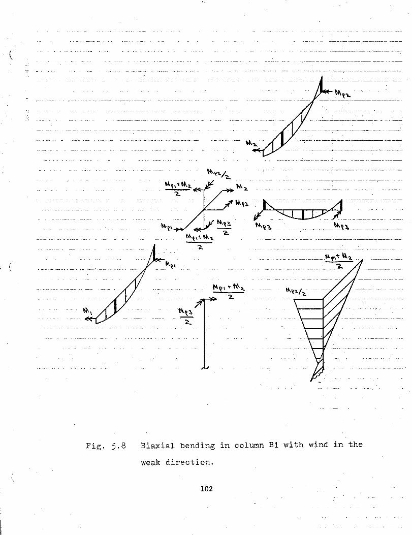
(
-----------~l~ --------------
------ ----- .... f\'t ~,: ( \ --------- -------'
Fig. 5.8 Biaxial bending in column B1 with wind in the
weak direction.
102-
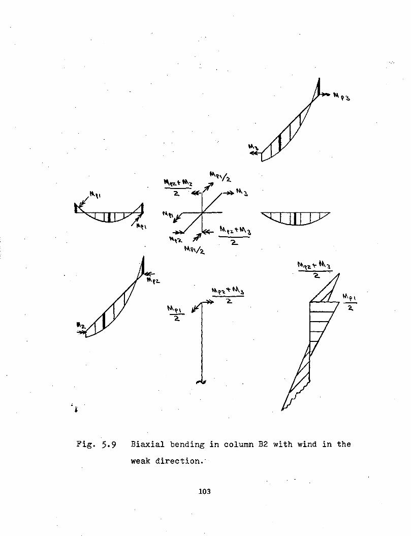
"'' ~I 'CIJIIJY
Fig. 5.9 Biaxial bending in column B2 with wind in the
weak direction.·-
103
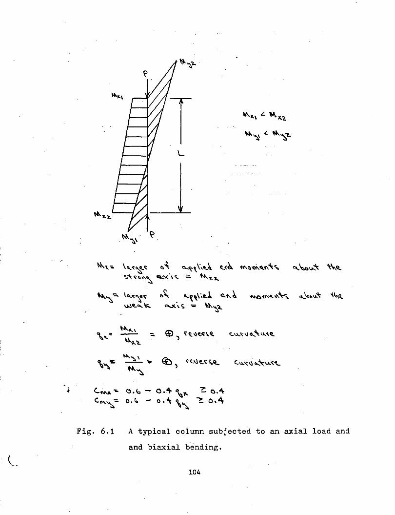
.:.
;:. ( il '-l ..
•
. N-.'\\.
"'-"--:. \~~~~ ~". ~~\\'~~ <L~ ff\a'"'-'-'l\~" ~~a\Jo..~ '\\..Q... ";,.~~I:>~~ Q.."'( \ ~ -:.. N..,._..l..
,.,., ':
\~
c..M.¥. 'I:.
c."~-:.
Fig. 6.1
~~ 0...~,\~(t.~ <!..C\,~ o.-K.\ ~ -= "-~c.
~"k\ e:>) ~'t'l)t..~~~ C:.\J...~ 'I) 0.... '\ U..\~ --"").,~
""~ \ --= ~~ .
~') H .. \le,..~~Q.. C..u.,.'ii;:'l) a.....~v..~ .......
~.c.:,-
0 ."\- '"' ~ o.4\
o.~ - o.~ \'\, ~ o,4-
A typical column subjected to an axial load and
and biaxial bending.
104
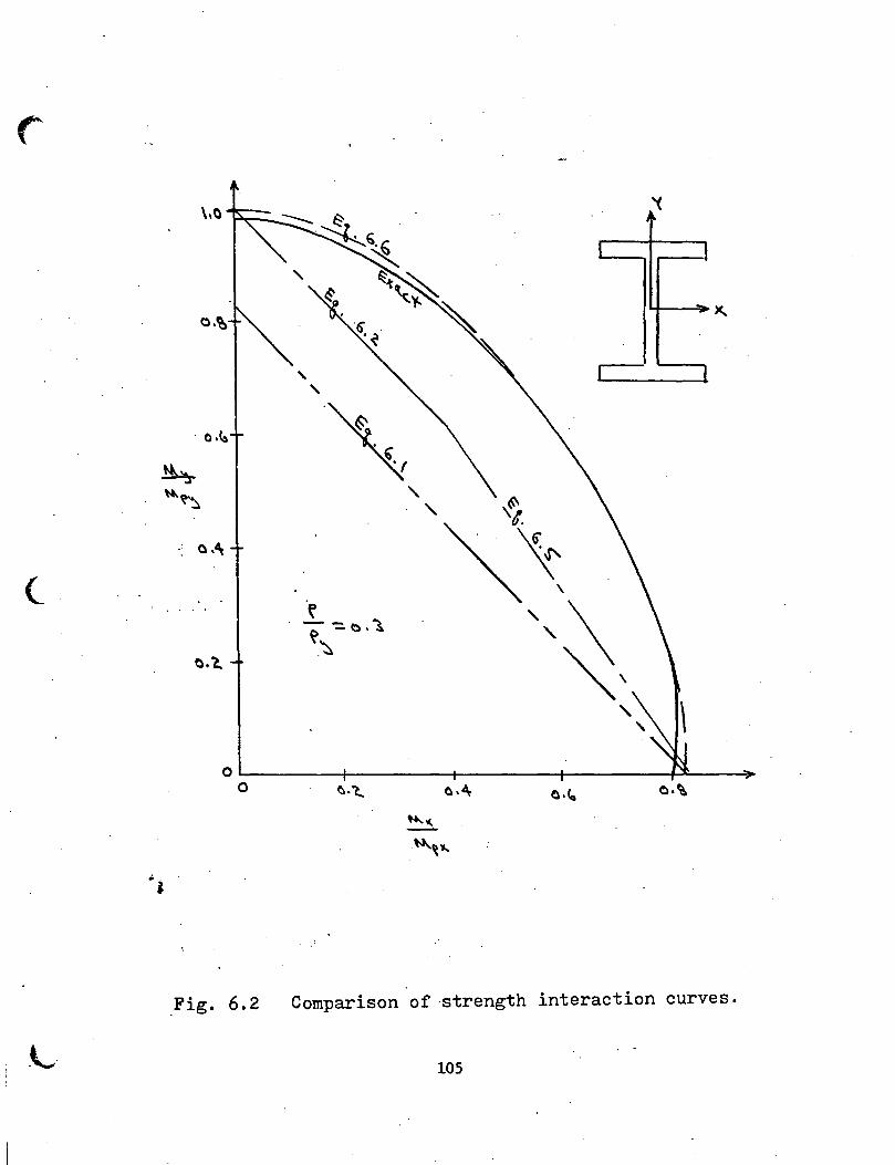
\,0 '(
l l
o.~ - X..
' 1 l
' . o.~ ~ ~ ' I
""'"~ ' ,~, o.~
(_ ~ ',\ ~ -::. 1:) • "l
C),l,. -~
"''
Fig. 6.2 Comparison of -strength interaction curves .
. L 105
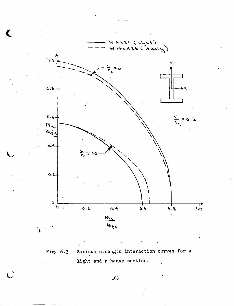
( 'N ~)C.~\ <.. \ .. \~\.-~)
--- 't-l \~ 1-. ~ 'l,.(:, <...~~'I~)
\,()
\... i ~(.
-:::.o
~ o.~ ~ X
" ~ " ~ !.. : 0 .~
-~ ~"
~ '\
~ 1... " ~ -- +o ~ - ' (.
' ~ " o. 't. \ \
\ \ \
0 I 0 o. L. (), ~ o.~ I. o.~ \,Q I
I W\"' I -
~~"' ' ~
I i
I
I Fig. 6.) Maximum strength interaction curves for a ..
light and a h~avy section.
~ L' 106
l
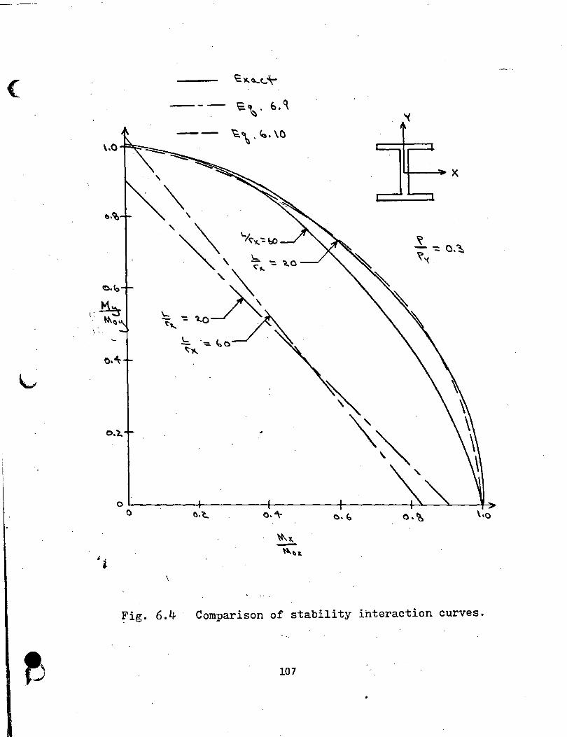
( ~~0....(.:~-
--- ~\· o.~ '(
-- ~\.to. \C \.0
-....:::::::::
O.l.
o.~
~ig. 6.4 . Comparison of stability interaction curves.
107
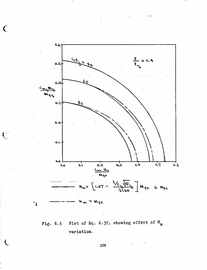
(
.:t
l
G~~--------------------------------------~
0.0
a.o 0.\ o.~ a.'l OA· ~.'S'
c..'N\.,. \.).II..
~V·
-·--·---- \ ~. ~ ..... -= \_\.0( ~ ~~~ ~~ }»-
~\bo . ~~ f:. ~~1(...
-- ~ 'C'C\ -: '""~ ~
Fig. 6.5 Plot of Eq. 6.)7, showing effect of Mm
variation.
108
o.~
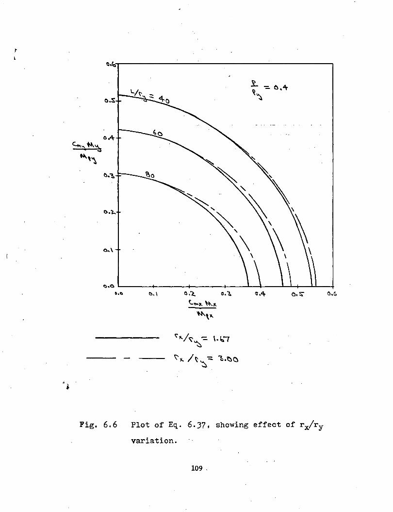
i. I
a.'s~---------------------~
o.s
Fig. 6.6
~"/r;;: -::. \.~., ~
\'~t. ~~ : ~.t)O ~
Plot of Eq. 6.37, showing effect of rx/ry
variation.
109-
i
10. APPENDIX I - DESIGN AIDS
DA-I: Properties of Beam - Columns DA-II: Strength Interaction Curves DA-III: Stability Interaction Curves
110
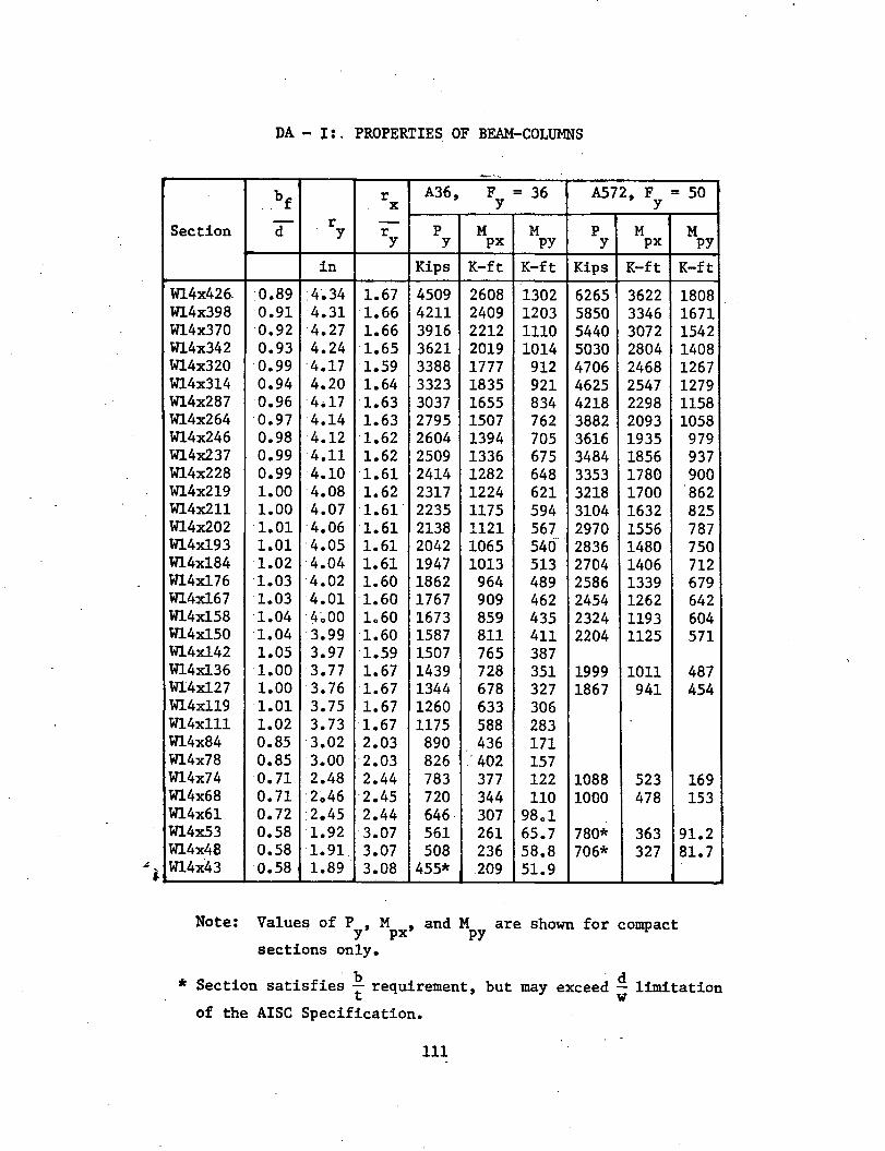
DA- I:. PROPERTIES OF BEAM-COLUMNS
--~-· .....
b r A36, F = 36 A572, F = 50 .. f X y y - r -Section d y r p M M p M M y y px PY y px py
in Kips K-ft K-ft Kips K-ft K-ft
W14x426. 0.89 •4~34 ·1.67 4509 2608 1302 6265 3622 1808 W14x398 0.91 4.31 ·1.66 4211 2409 1203 5850 3346 1671 W14x370 ·0.92 4.27 ·1.66 3916 2212 1110 5440 3072 1542 W14x342 0.93 ·4.24 1.65 3621 2019 1014 5030 2804 1408 W14x320 0.99 4.17 1.59 3388 1777 912 4706 2468 1267 W14x314 0.94 4.20 1.64 3323 1835 921 4625 2547 1279 W14x287 0.96 4.17 1.63 3037 1655 834 4218 2298 1158 W14x264 0.97 4.14 1.63 2795 1507 762 "3882 2093 1058 W14x246 0.98 4.12 1.62 2604 1394 705 3616 1935 979 W14x237 0.99 4.11 1.62 2509 1336 675 3484 1856 937 W14x228 0.99 4.10 1.61 2414 1282 648 3353 1780 900 W14x219 1.00 ·4.08 1.62 2317 1224 621 3218 1700 862 Wl4x211 1.00 4.07 1.61 2235 1175 594 3104 1632 825 W14x202 1.01 4.06 ·1.61 2138 1121 567 2970 1556 787 Wl4x193 1.01 ·4.05 1.61 2042 1065 540 2836 1480 750 W14xl84 1.02 ·4.04 1.61 1947 1013 513 2704 1406 712 Wl4x176 1.03 4.02 1.60 1862 964 489 2586 1339 679 Wl4x167 1.03 4.01 1.60 1767 909 462 2454 1262 642 Wl4x158 ·1.04 ·4~00 loGO 1673 859 435 2324 1193 604 W14xl50 1.04 3.99 ·1.60 1587 811 411 2204 1125 571 W14xl42 1.05 3.97 ·1.59 1507 765 387 Wl4x136 1.00 3. 77 1.67 1439 728 351 1999 1011 487 Wl4x127 1.00 3.76 1.67 1344 678 327 1867 941 454 Wl4x119 ·1.01 3.75 1.67 1260 633 306 Wl4xlll ·1.02 3.73 1.67 1175 588 283 W14x84 0.85 ·3.02 2.03 890 436 171 W14x78 0.85 ·3.00 ·2.03 826 . 402 157 W14x74 0.71 2.48 2.44 783 377 122 1088 523 169 W14x68 0.71 2~46 2.45 720 344 110 1000 478 153 W14x61 o. 72 2.45 2.44 646 307 98ol Wl4x53 0.58 1.92 3.07 561 261 65.7 780* 363 91.2 W14x48 0.58 1.91 3.07 508 236 58.8 706* 327 81.7 W14x43 0.58 1.89 3.08 455* .209 51.9
Note: Values of P , M , and M are shown for compact y px py sections only.
. b . d * Section satisfies t requirement, but may exceed w limitation
of the AISC Specification.
111
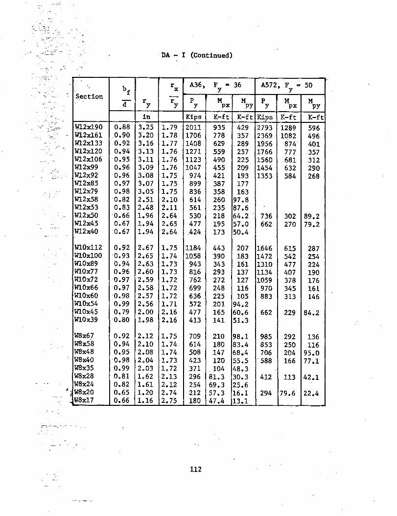
. ., ___ . ~
· DA - I (Continued)
- - -- . - ~' ' ---
A36, F = 36 A572, F = 50 ' bf r
X y y S~ction - M r r p M p M M d y y y px py y px py
in Kips K-ft K-ft Kips K-ft K-ft ... - :-:... -
--·--··~---- Wl2x190 0.88 3.25 1. 79 2011 935 429 2793 1289 596 -- Wl2x161 0.90 3~20 1.78 1706 778 357 2369 1082 496
W12x133 0.92 -3.16 1. 77 1408 629 -289 1956 874" 401 Wl2x120 0.94 -3.13 1.76 1271 559 257 1766 777 357 W12x106 0.95 3.11 1.76 1123 490 225 1560 .681 312 W12x99 0.96 3.09 1.76 1047 455 209 1454 632 290 W12x92 0.96 3.08 1.75 974 421 193 1353 584 268 Wl2x85 0.97 3.07 1.75 899 387 177 W12x79 0.98 ·3.05 1.75 836 358 163 W12x58 0.82 2.51 -2.10 614 260 97.8 W12x53 0.83 2.48 2.11 561 235 87.6 W12x50 0.66 1.96 2.64 530 218 64.2 • 736 302 89.2 W12x45 0.67 1.94 ·2.65 477 195 57.0 662 270 79.2 W12x40 0.67 1.94 ·2o64 .424 173 50.4
Wl.Ox112 0.92 2o67 1.75 1184 443 207 1646 615 287 W10x100 0.93 ·2.65 1.74 1058 390 183 1472 542 254 W10x89 0.94 2.63 1.73 943 343 161 1310 477 224 W10x77 0.96 ·2.60 1o 73 816 293 137 1134 407 190 W10x72 0.97 2.59 -1.72 762 272 127 1059 378 176 W10x66 0.97 ·2.58 1.72 699 248 116 970 345 161 Wl.Ox60 0.98 ·2.57 1.72 636 225 105 883 313 146 Wl.Ox54 0.99 2.56 1. 71 572 201 94.2 W10x45 0.79 2.00 2.16 477 165 60.6 662 229 84.2 W10x39 0.80 1.98 -2.16 413 141 51.3
W8x67 0.92 2.12 1.75 709 210 98.1 985 292 136 W8x58 0.94 2.10 1.74 614 180 83.4 853 250 116 W8x48 0.95 ·2.08 1.74 508 147 68.4 706 204 95.0 W8x40 0.98 2o04 1.73 423 120 55.5 . 588 166 77.1 W8x35 0.99 2o03 1o72 371 . 104 48.3 W8x28 Oo81 lo62 2.13 296 81.3 30.3 412 113 42.1 W8x24 ·0.82 1.61 2.12 254 69.3 25.6
i W8x20 Oo65 1.20 2o74 212 57.3 16.1 294 79.6 22.4 W8x17 0.66 1.16 2.75 180 47.4 13.1
112
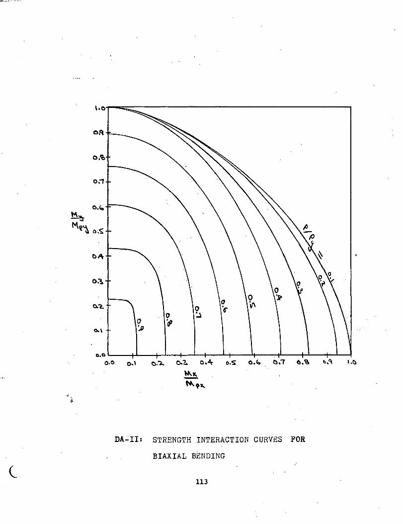
(_
a.o~--~--~~--+-~-+--~~--~--~~--~---+~~
o.o o.\ o.'l.. o.~ o.4\- o.s o.b o.-r o.~ ~.<\
~ ~.,
DA~II1 STRENGTH INTERACTION CURVES FOR
BIAXIAL BENDING
113
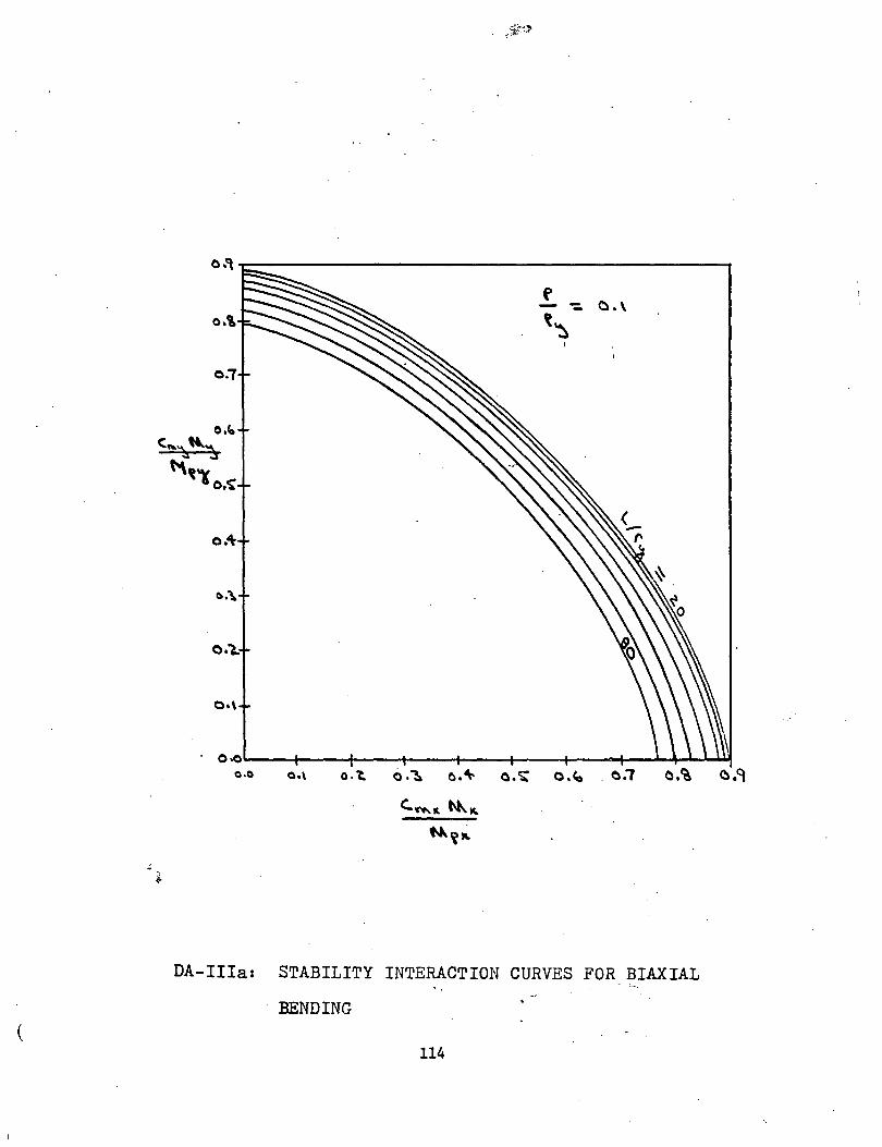
I I l \
(
o.\
0."7
0•\
0~~--4----4----+----+----r---~--~~--~~~ a.o Oo\ o. 't. a:~ o.~ o.~ o.<o . o."'T o.t?, o.'l
DA-IIIa: STABILITY INTERACTION CURVES FOR BIAXIAL
BENDING
114
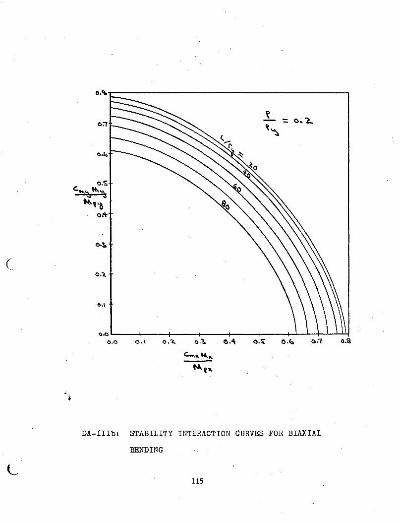
0:7
C. 0.1,
0~----~----~----~-----+-----+----~~~-r~~~
o.o o.\ o.~ o.~ o.~ o . .., o.a
DA-IIIb: STABILITY INTERACTION CURVES FOR BIAXIAL
BENDING
L 115
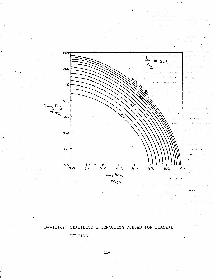
( \
o.s
o.-a
0.\
\l -- - - -- - . -- -::. <:). ~
~~
0~~----+-----+-----~-----+----~~~~~~~
0.0 . O.\ o."' o.~ _ o." ___ o:T
DA-"IIIc: STABILITY INTERACTION CURVES FOR BIAXIAL
BENDING
116
---;
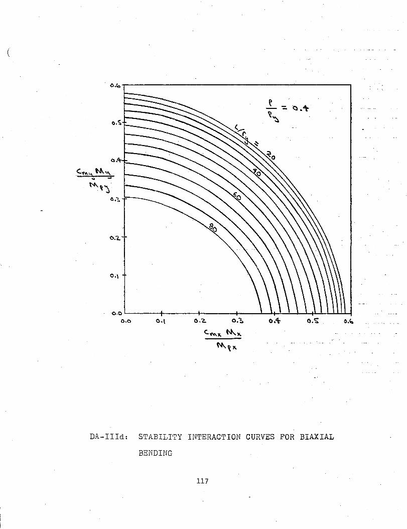
(
. o.~T---------------------~--~----------------~
o.,.
o.~ L.------+-------+--------+------~.---~...,_.-.:...~~f.l-l.--'-.~,...~..~....l...l
o.o o.'\- o.-s; 0.'-
DA-IIId: STABILITY INTERACTION CURVES FOR BIAXIAL
BENDING
117
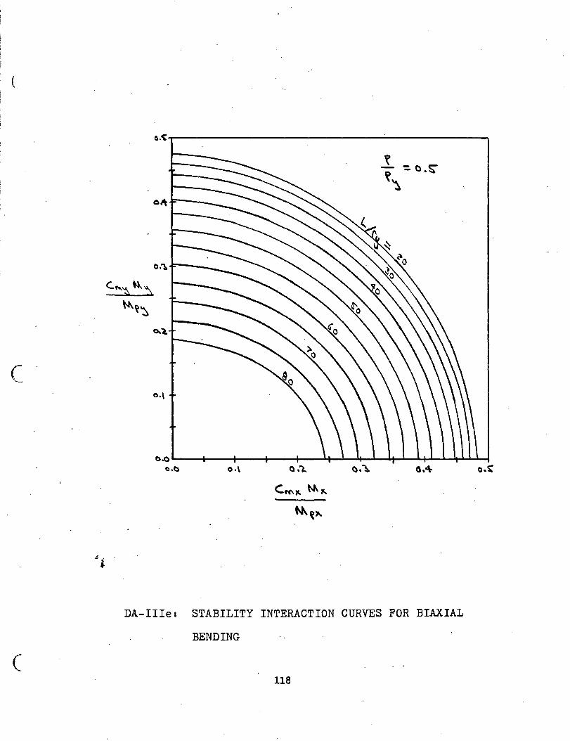
c
(
a.<,-------------------------.
o.o ...._-+---+---+--+-_....t-l~~..__~..~.-......... ..__L.....lt..I...L...Io......j o.o a.4
DA-IIIe: STABILITY INTERACTION CURVES FOR BIAXIAL
BENDING
118
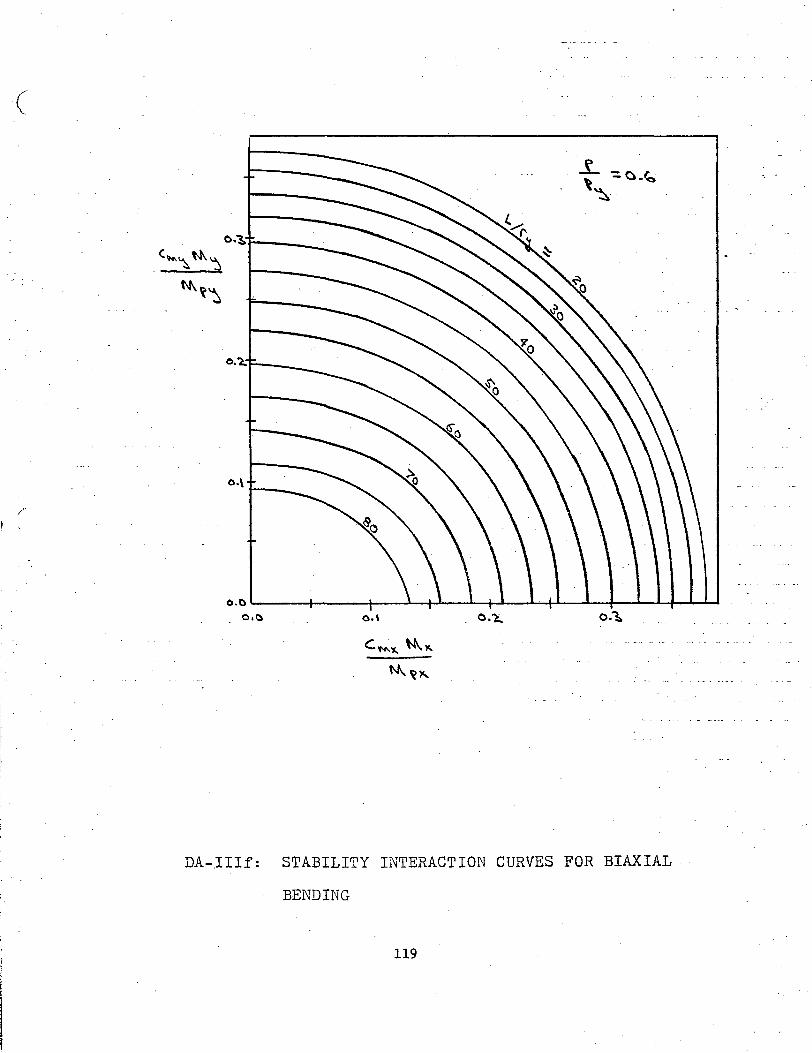
( \ ..
0.'3>,__ __ _
.(~~ ~~
~~~
o.o~----r-----r---~~--~~--~+L--~+-~~4-~~ 0,1;) o.\ O.'l, o.~
DA-IIIf: STABILITY INTERACTION CURVES FOR BIAXIAL · ·
BENDING
119
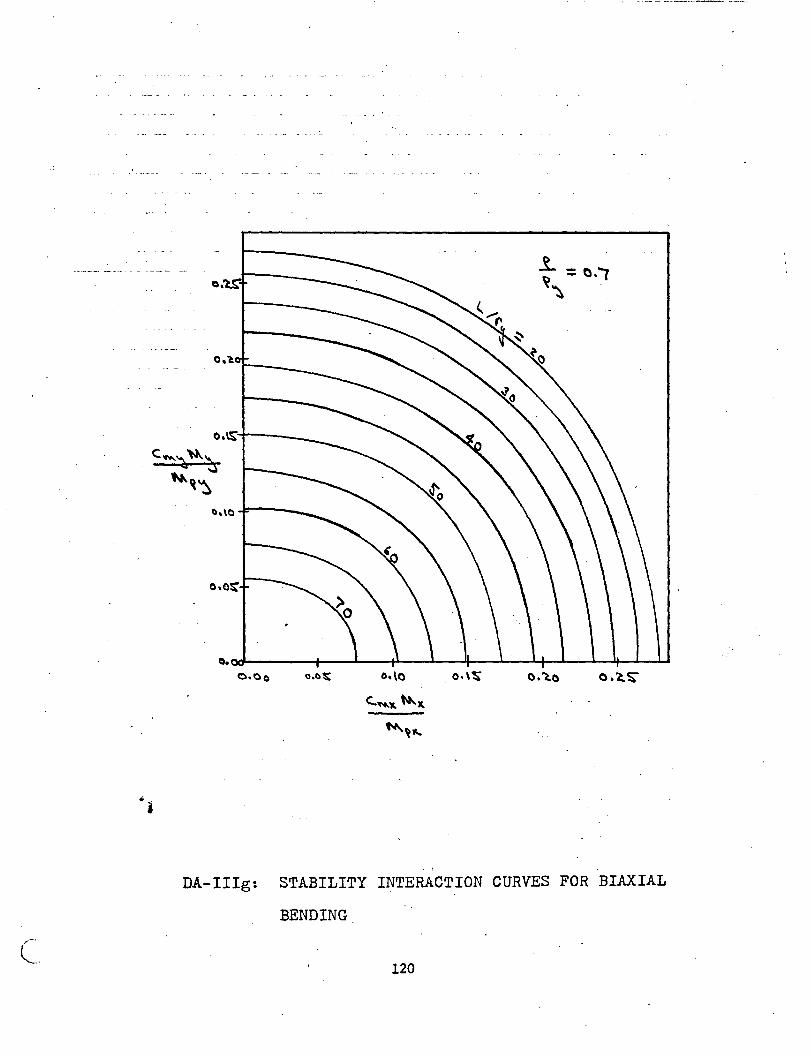
•
(_.
o.~:-r----
C ""'). ~ \:s .... ~~
i
o.ol!i: o.\o
.. -
..t. =a.( ~~ .
o.,a
DA-IIIg: STABILITY INTERACTION CURVES FOR BIAXIAL
BENDING
120
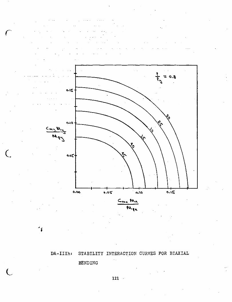
L
DA-IIIh: STABILITY INTERACTION CURVES FOR BIAXIAL
BENDING
121 ·'
11. APPENDIX II - COLUMN DESIGN EXAMPLES
122
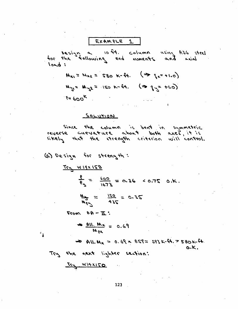
\' <;:.\~"' ~ \.C) ~. ~o~ ~'- ~o\\ov..)\f\~ ~"~ \oe....6 ~
~~ '::. \k'\"1.. ": . \ ~0 \:...- ~'\.
~': ~00~
\)...~,"~ ~·:~~ ~'\e~\ ~"'~ &...~\~
\~ \-.= ~\.o)
t~ \ ~':. ~,.0)·
~\."'-L'-. ~~ C..C)\\). ..... "C\ \~ ~~"(\~ \'t\ ~~ 'CII\. ~ ~ \--t \. <::_
~~f..~ \" \' u.l\ \\ <.a"'~\.
c..u..~" 0.... ~ v..~ q, o....~u.... ~ ~~ N!...\l4l.o('"'Q.
\\~~\'\ ~o..'\ ~~ ~"~q_~~ ~t\'\ ... ~\~<'-
~") ~4a. ~\~'C\ ~M· ~\~fl.'C\~ ~ •.
\('~ 'N \"\X\~~
...- ~\\. ~, : O.b~
~~"
\~ ~~ ~~'\: \~~~~(' ~q,_c_\\oC\ ••
'\" w \4\~\*Q . ..s
123
0 ,'f::;. •
o.~.
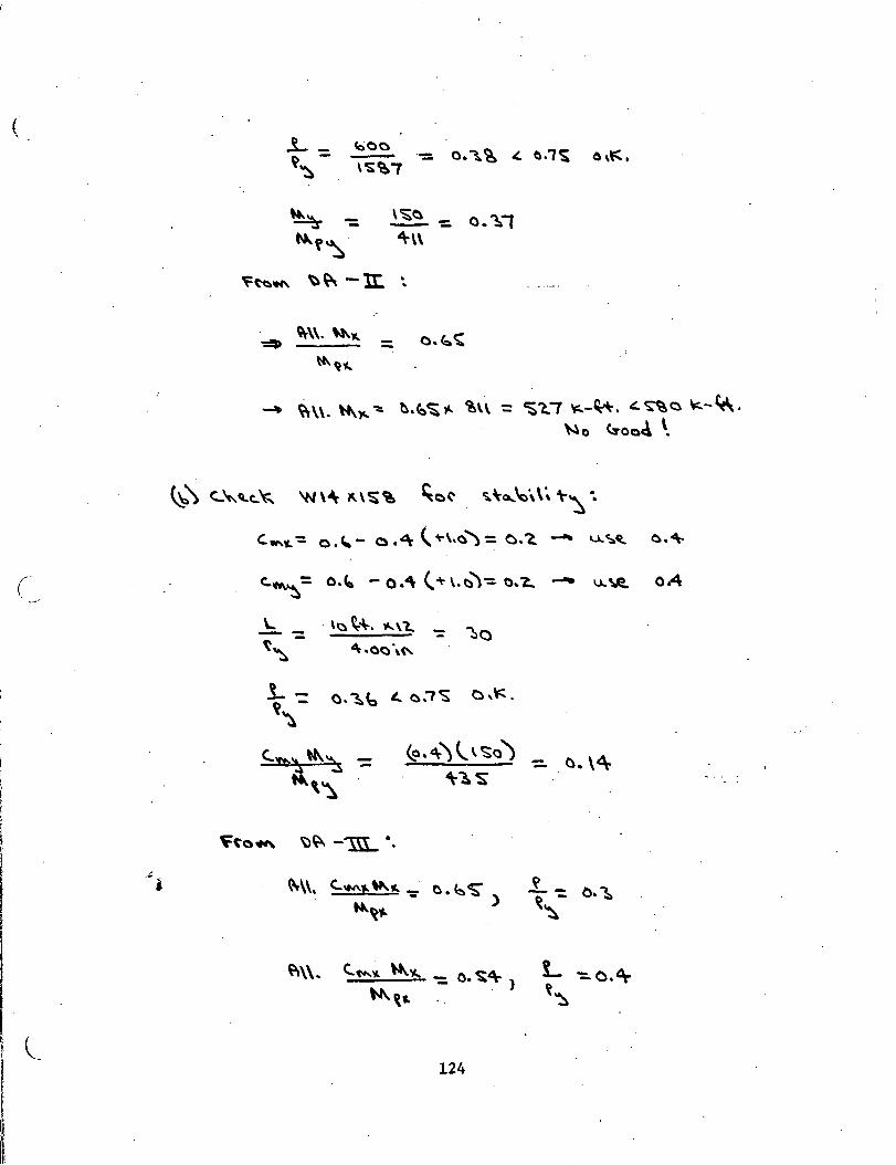
(
t C. l I I
.. i
\~~ -: 0.'1, 4\-\\
~ ~\\. ~~ ~ ~.(o~,._ ~H : ~1.7 ~-~~. ~~o \o::..-~. ~o <.:roo4 \.
~\ <..~~c..~ 'N\~ ~\~'e ~a(' ~\o...\o',\~ t-~ ••
"-"-= o.~- o.4\ (.~\.a"): o.'2. ~ u..~~ o."\-
\.. --t~--\- -= o. ~~ ~ o.7'S c '". ~
- . o. \~
~\\. c...OM.J.. \I>.. ,c. -= C). b CS' ) ~~.,.
124
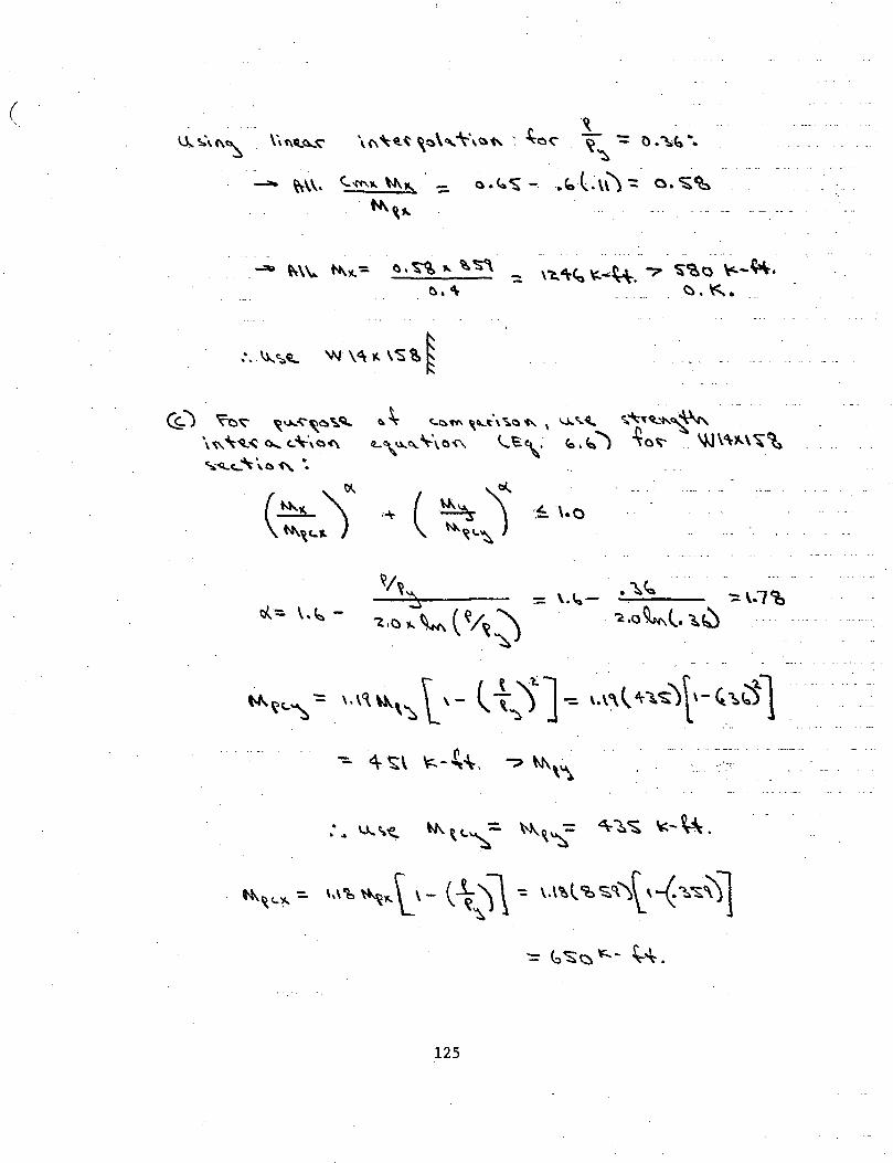
(
- ~\\.
-~
\(\"t~~ ~~\, '\\~~ ~ .£.o, ~ -:: ~
<..'('f'\.,.~~ _ a.~~- .. foC\\):: . ~,,..
-·
'::: \~4\-~ ~""~. ? ~~0 \"--~. ~.~.
(1.) ~~ ~~",~ ~~ e. S., ~~:)""' \'-~\":.a "'- I \,J,. '~ <;.~"tQ...~~ \~~~~o....c:~·\(:)(\ tL\.u...~~t\a'<'\ (...e\: e:..b) ~o~. \JJ\<\,_\~~ ~<Lc:.... ~\a"'- ••
~~~~~ ( ~/~ ~ . ~
~~ .. ~, '·I'\~,,. L,- l ~s 1.,. ,.,,, -~-.. ">l,_, "\,ctl
: .. u.~~ ~\<..~:. w...~~- ~~~ ~-~.
1'1\~c,._:. \,\'1, ~ .. \_I- ( ~.Jl ~ \.\'!.\ 'M:.'\')~,-( "l.";;.\)l
125
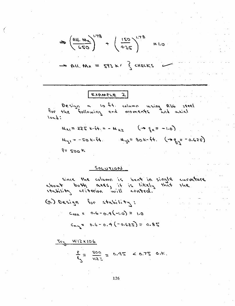
/
t)~ ~\"':::,.'<\ 0... \~ ~'. ~ot' \-""-~ ~o\~a'.)..l\'C\~ ~~c\. \C)~~:
~"\ \ -= - ':i:o \:- ~.
:~ -= 'S:o c \:;.
~I
t.o\I.)..'N'.'I' u,_ .. ,;,t\~ ~~ '.\~~~\ '(\1\t) 1M. ~-('.~'i,. 0...11\~ o...."lo..\o...\
~\N.::~.. '\-\,...~ c..~\1.)..'<'4\'(\ \<;.. ~~-t\~ \(\ ~\(\~Q,. ~~~~~ ~t)~ ~!'..~':..) \\- \~ \,~~\~ ""'CI....-\-\.~\0\ \·, ~ c..~\\-«-\.~'(\ .. ~\ \\ c:..o\1\.'\-\a\.
~ J ~ Q.. ~\ ~ '(\ \o t' 5:.. ~a...~\ \ ~ ""~ "..
c:.'C'f\,_ -: o.b- ~.'\ l-\,Q) :: \.o
\{ ... ) w n. 1<. \c ~ ..J
126
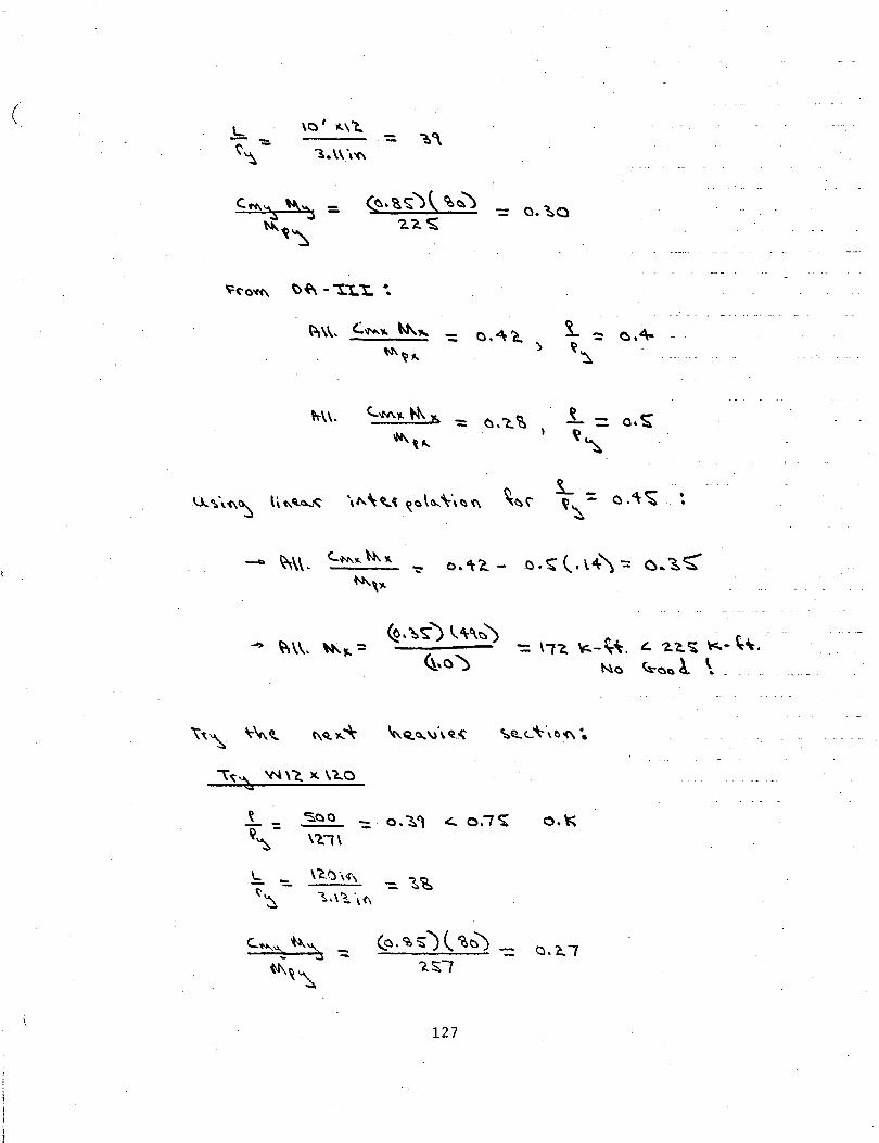
(
- o.~o
_ o.4'a. )
M\.
~ <so o - .., ~ 7 c--- _ o.~, c::.. o. ~
'<~- \1."1\ -
'- -- -t~
\~~'"" 1..\~\(\
127
o."
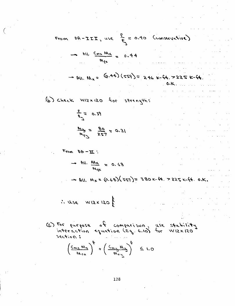
(
- ~\. »..., ~ ~.4~) (~~~\= 'a'\~~-~.'?~~~~-~ . .. o.~.
~ l <..\-.~c..~ 'N\~ )(. \C.O ;o~ ·~'\~<tf\~'l-~ •.
~ -: ~.~, ~
- ~\\. N\"" -N...~~
-. ~\\. »..~ ~ (o.b~)(-s~)-= ~~c ~-~.? ~~~ \::.-~. o.~.
~) ~0, \~ .•. :(',()';.~ 0~ C..<:::~of't\~(t...(\"S:.Qf\ ') ~\\1,. \""\~~ o.....c... \-\o-f\ ~\ V...ll.."\~-4\ l...t'. ~. \<)') ~a~
128
S\-~ \,', \\"\~ w \(. )(. ll.. 0
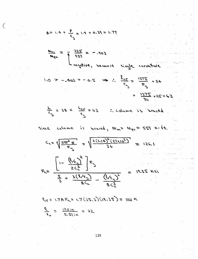
( t=-= \, '\ + .f.. =- \.<\ ~ o. ~':. \. 7'
t~
\ .a 7 - • ~'1 "'? - ~. ~ -:::!> :'
·~ 2-~E I
l.. (::..\ 4)1.. ( '2..~ 11..\t)") C.c_~ -
~~ ~'o
l\- ~ . .)~ 1 ~\ ~0....:::.
2.<.~ -
~ + 1.\ \/~~) (\/~~)~. ~
~C.c... ~<..l
~ - \C...Q \<'\
\.,.. ;::;. ~\ \ (\
129
- \c.~.\ -
\<\..~ ~ ~c;.\
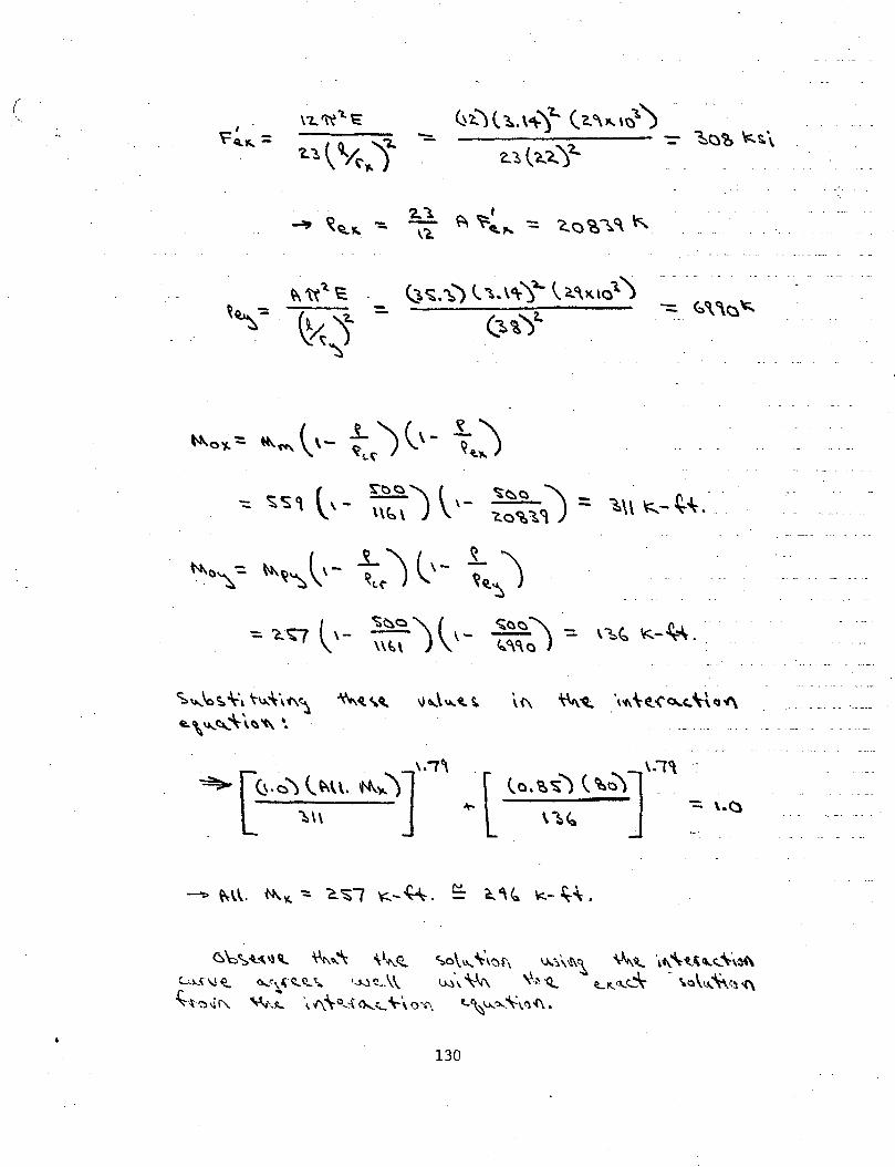
( \"Z..~'t.~ ~~) t ~. '"""l~ (2. 'JC.. \1;)1.)
r I .
~<::')~ 'f:..s.\ ~Q..JC.. = "~~ ~,..}~
"'::::. -2.:~ ( ?...~ '}-
'2..1. ' '2.C')~~C\ ~ ..:., ~Q..~ - - ~ ~ct."' -:: ,, . ·-· .....
~ 'tt't E ~~:~} (.1..\~)~ \C.<\.l(t01.)
~''t\" ~~'::: -\x1 (1.\)'l..
~
~\\ K- ~~ ...
C::."'-."oS.~~ \-l.l..,\'1\~ ~~,~ \1~\"t..S. \(\ ~'ct. \'f>,\~ ... ('o..c..\\~oi\ ~,~~"\-\~'(\ ·.
~\:.'S.~<\\alt. ~~~ '\~~ CS.o\~ ~\t:\{\ u-.-.\.·.s\\ "'~ \C\.'\-t.~Cl...t...\",,m C...:.A.~\l~ o..:-.,.s;·.:t~\. ·~~.\\ ~\ ~ \'.:-.-<t_ LK<\..c__""' .. \o\u..'\·VH\
~'\~-if\. ~'.;:, ·~ (\'\c_..t G....'-.'\--\ 0'""· t..~~J..o..:\=1.~-1\ •
• 130
I
12. REFERENCES
1. American Iron and Steel Institute PLASTIC DESIGN OF BRACED MULTISTORY STEEL FRAMES, New York, 1968.
2. Driscoll, G.C. Jr., Takanashi, K., and Gsellmeier, R.L., PLASTIC DESIGN OF UNBRACED MULTISTORY STEEL FRAMES, Fritz Engineering Laboratory Report No. 367.12, Lehigh University, in preparation.
3. Reed, P.W. SIMPLIFIED ANALYSIS OF UNBRACED FRAMES, Fritz Engineering Laboratory Report No. 367.9, Lehigh University, May 1972.
4. American Society of Civil Engineers PLASTIC DESIGN IN STEEL - A GUIDE AND COMMENTARY, ASCE M & R No. 41, New York, 1971.
5. Hansell, W.C. PRELIMINARY DESIGN OF UNBRACED MULTI-STORY FRAMES, Ph.D. Dissertation, Lehigh University, 1966, University Microfilms, Inc., Ann Arbor, Michigan.
6 •. Driscoll, G.C., Jr., Armacost, J.O., III, and Hansell, W.C .. PLASTIC DESIGN OF MULTI-STORY FRAMES BY COMPUTER, Journal of the Structural Division, ASCE, Vol. 93, STl, January 1970.
7. Daniels, J.H. COMBINED LOAD ANALYSIS OF UNBRACED FRAMES, Ph.D. Dissertation, Lehigh University, 1967, University Microfilms, Inc., Ann Arbor, Michigan
8. Daniels, J~H •.
9.
A PLASTIC METHOD FOR UNBRACED FRAME DESIGN, Engineering Journal, AISC, Vol. 3, No. 4, October 1966, P. 141-149. .
Driscoll, G.C., Jr., et al. PLASTIC DESIGN OF MULTI-STORY FRAMES -- LECTURE NOTES, Fritz Engineering Laboratory Report 273.20, Lehigh University, 1965.
10. Parikh, B.P., Daniels, J.H., and Lu, L.W. PLASTIC DESIGN OF MULTI-STORY FRAMES -- DESIGN AIDS, Fritz Engineering Laboratory Report 273.24, Lehigh University, 1965. ·
131
I
I ! I !
I l
I
11. Daniels, J.H. and Lu, L.W. THE SUBASSEMBLAGE METHOD OF DESIGNING UNBRACED MULTI-STORY FRAMES, Fritz Engineering Laboratory Report No. 273.37, Lehigh University, March, 1966.
12. Daniels, J.H. and Lu, L.W. DESIGN CHARTS FOR THE SUBASSEMBLAGE METHOD OF DESIGNING UNBRACED MULTI-STORY FRAMES, Fritz Engineering Laboratory Report No. 273.54, Lehigh University, November, 1966.
13. Driscoll, G.C., Jr., and Armacost, J.O. THE COMPUTER ANALYSIS OF UNBRACED MULTI-STORY FRAMES, Fritz Engineering Laboratory Report No. 345.5, Lehigh University, 1968, Document AD670 742, Clearing house.
14. Chen, W.F., and Santathadaporn, s. REVIEW OF COLUMN BEHAVIOR UNDER BIAXIAL LOADING, Journal of the Structural Division, ASCE, Vol. 9~, ST 12, December 1968.
15. Johnston, B.G., Editor THE COLUMN RESEARCH COUNCIL GUIDE TO DESIGN CRITERIA FOR METAL COMPRESSION MEMBERS, Third Edition, to be published.
16. Ringo, B.C. EQUILIBRIUM APPROACH TO AN ULTIMATE STRENGTH OF A BIAXIALLY LOADED BEAM - COLUMN, Ph.D. Dissertation, University of Michigan, 1964.
17. Pfrang, E.O., and Toland, R.H. CAPACITY OF WIDE FLANGE SECTIONS SUBJECTED TO AXIAL AND BIAXIAL BENDING, Dept. of Civil Engineering, University of Delaware, Newark, Delaware, 1966.
18. Morris, G.A., and Fenves, S.J.
19.
20.
APPROXIMATE YIELD SURFACE EQUATIONS, Journal of the Engineering Mechanics Division, ASCE, Vol. 95, No. EM4., Proc. Paper 6741, August 1969.
Santathadaporn, S., and Chen, W.F. INTERACTION CURVES FOR SECTIONS UNDER COMBINED BIAXIAL BENDING AND AXIAL FORCE, Welding Research Council Bulletin No. 148, February, 1970.
Chen, W.F., and Atsuta, T. INTERACTION EQUATIONS FOR BIAXIALLY LOADED SECTIONS, Journal of the Structural Division, ASCE, Vol. 98, No. ST5, Paper·8902; May, 1972.
132
21. Chen, W.F., and Atsuta, T. INTERACTION CURVES FOR STEEL SECTIONS UNDER BIAXIAL BENDING, .The Engineering Journal, E. I.e., Vol. 17, No. A-3, March/April, 1974.
22. Tebedge, N., and Chen, W.F. DESIGN CRITERIA FOR STEEL H-COLUMNS UNDER BIAXIAL LOADING, Journal of the Structural Division, ASCE, · Vol. 100, No. ST3, Proc. Paper 10400, March, 1974.
23. Pillai, J.S. BEAM COLUMNS OF HOLLOW STRUCTURAL SECTIONS, to be published in the Journal of the Canadian Soc_iety for Civil Engineering.
24. Johnston, B.G., Editor THE COLUMN RESEARCH COUNCIL GUIDE TO DESIGN CRITERIA FOR METAL COMPRESSION MEMBERS, Second Edition, John Wiley and Sons, Inc., New York, 1966 •
. 25. Go.odier, J .N. TORSIONAL AND FLEXURAL BUCKLING OF BARS OF THIN WALLED OPEN SECTIONS UNDER COMPRESSIVE AND BENDING LOADS, J. App. Mech., Transactions ASME, Vol. 64, Sept. 1942.
26. Culver, C.G. EXACT SOLUTION OF THE BIAXIAL BENDING EQUATIONS, Journal of the Structural Division, ASCE, Vol. 92, No. ST2, April, 1966.
27. Culver, C.G. INITIAL IMPERFECTIONS IN BIAXIAL BENDING, Journal of the Structural Division, ASCE, Vol. 92, No. ST3, June, 1966.
28. Santathadaporn, S., and Chen, W.F. ANALYSIS OF BIAXIALLY LOADED H-COLUMNS, Journal of the Structural Division, ASCE, V:ol. 99, ST3, March, 1973.
29. Birnstiel, C., and Michalos, J. ULTIMATE LOAD OF H-COLUMNS UNDER BIAXIAL BENDING. Journal of the Structural Division, ASCE, Vol. 89, No. ST2, April, 1963.
30. Harstead, G.A., and Birnstiel, C. INELASTIC H-COLUMNS UNDER BIAXIAL BENDING, Journal of the Structural Division, ASCE, Vol. 94, No. STlO, October, 1968.
133
31. Birnstiel, c. EXPERIMENTS ON H~COLUMNS UNDER BIAXIAL BENDING, Journal of the Structural Division, ASCE, Vol. 94, No. STlO, October, 1968.
32. American Institute of Steet Construction, Inc. SPECIFICATION FOR THE DESIGN, FABRICATION AND ERECTION OF STRUCTURAL STEEL FOR BUILDINGS, New York, February, 1969.
33. Okten, O.S., Morino, S., Daniels, J.H., and Lu, L.W. EFFECTIVE COLUMN LENGTH AND FRAME STABILITY, Fritz Engineering Laboratory Report 375.2, Lehigh University, November, 1973.
34. Canadian Standards Association STEEL STRUCTURES FOR BUILDINGS, CSA ·standard Sl6~1969, Ontario, December, 1969.
35.. Hibbard, W. R. and Adams, P. F. SUBASSEMBLAGE TECHNIQUE FOR ASYMMETRIC STRUCTURES, Journal of the Structural Division, ASCE, Vol. 99, No. STll, November, 1973.
134
13~ VITA
The author was born January 11, 1952 in Munich, West
Germany. He came to the United States with his parents in 1955.
He holds a Bachelor of Science Degree in Civil Engineering from
Rensselaer Polytechnic Institute, June, 1973. During ·the past
two years he has been a Research Assistant at Lehigh University,
and will receive his Master of Science Degree in Civil Engineer
ing from Lehigh University in May, 1975.
The author and his wife presently reside in Bethlehem,
Pennsylvania.
135