Embed Size (px)
Citation preview

Proposal to
AISC Committee on Composite Design
for
FATIGUE STUDIES OF
COMPOSITE STEEL AND CONCRETE BEAMS
FRITZ ENGINEERINGLABORATORY LIBRARY
by
R. G; Slutter
D. C. King
G. C. Driscoll, Jr.
April 1962
Fritz Engin~ering Laboratory Report No. 285.4

PROPOSAL
TO
for
FAT! STUDIES OF
COMPOSITE STE~L AND CONCRETE M~~~6&Y
by
R. Go SlutterD. C. Kirjg
G. C. Driscoll, Jr.
; ... .....~, .......~ ....... ' .... ••..~- ... ~ ....... , • ..,111 ~.. ~
Fritz ~lgineering LaboratoryDepartment of Civil Engine~ring
I-jshigll University,.Be1;?~.lehenl,Penrlsylvaniti·
April 1962
FT!tz :E'n

2d5 0 4
PROPOSAL~~-
for
by
He Go Slut tarDo Co King
G. Co Driscoll, Jrb
The knO'ftl1edge of the I:'81'Qfol'amance of compos! te steel and
concrete beams under fatigue loading has been advanced re~
cently 8S a result- of teats ot four beams conducted at Fritz
Engineering Laboratory. These tests produced fatigue failure
of 1/2 inch diameter "Lit welded stud shear connectors.
From these and other tests, it 1s ~o9s1ble to approximately
establish a failure cu~ve for fatigue loadlng~ However, furtber
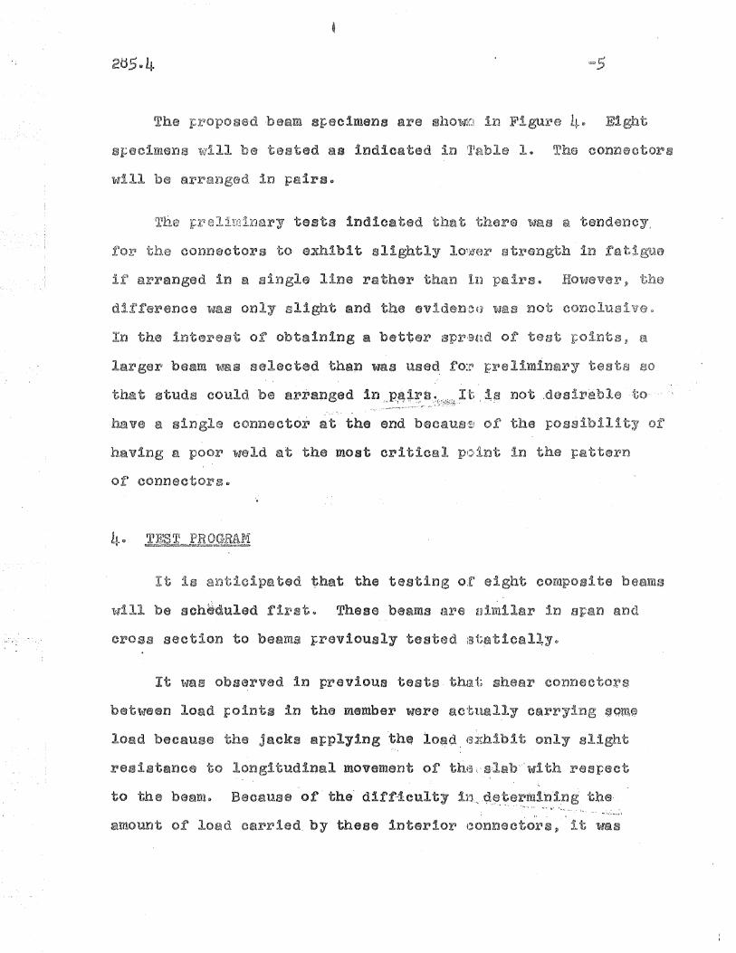
tests are necGs~ary to justify this failure curve. The fatigue
failure reeults are presented in the form of number of cycles
(N) to failure versus stress (5) in Figura 16
The upper curve of Figure 1 shows results of testa ob~
talned from preliminary beam te3ts~ The lowe~ curve show~ ~~~
8ult8 of tests from pushout testss Since Figure 1 at log
scale re~resentation of the r~sults, the ~umerlcal difference
between the curves is not a's large, it may seem at first gla~ce~. ~ .. ~ ~ .... \

=2
could serve as a design curve. The curve ~ushout s~eclmens
It is proposed that more beam tea
failure curve ror 1/2 l~ch diameter studsQ It is necessary to
obtain sufficient number of data points so i:~hat a stat:Lst;ical
Q11alysis can be lTInde 0 In add! tioD 1 t ls ~:~()poaed.. to m~lke
adaitlonsl s of pushout specimens to batter establish this
failure curveD It is anticipated that othsr variables such ~8
the size effect of connectors, effect of rsverssl or loading,
and effect or concrete strength can be Inv~stigated only by
-rneane of the morel economical pushout metho;cls Q
2e OBJECTIVES OF TESTS~ >iii wz::m
The tests completed to date Indlc~rte "that it is t:'ossipl~ to
GBtablish en Se=N CLlrve such as Figure 1 fo:r -the fatigue strength
of connectors~ However, the number of dBt~ points svail$ble at
tln16 is not sur.rlcient to dete:rlulne either tl18
correct I:0S :1.011 or shape of the curve :"or megni tude of tf16
As a result of the experience gained in the previous tests,
it is possible to make cer<ta1n changes 'in t;r~e test specimens 'tflhicl~
will make the interpretation or results mora meanin
changes ara diacu3sed further in the next section o£ the r6~orto

It ia
t ol~ .3/L~. H
2U504
" stud!! since this s5Lze l~j frequent;ly used j~ll
bridge construction $ For this reason the :L!2 n dis 0 hoaded studi~
stead of' t,he: usuLsl 1 n d1amete~ Q
Since the failure curves for shear connector~ in beams and
pushout tests are nearly the same, it is da~lrable to prove
that the results or pushout tests can be sat18facto~ily used
to evaluate otl'ler varlab.les. It' ha.sbeen". (~stabl,ishe'd tQ,at the. ~'4.+t I ~.~. ;'-~~"'Ii.. "'~. \ .l~:-'~ ... ""_
:results of pushout; tests are co:n~~;vatlv~"io~'bo"tli"st'at":i'cand:
fatigue loadingq It 1s desirable to be able to make pushout
tests rather than beam testa because instrunlentatlon, testing
8I:parstus, 8i1d interf·retation of results Sl}~e simplier for PUSll~
out tests than for beam tests.
It was observed' during beam tests th;rt1t prior~ to f~ilure of
shear' connectors, there 1s 8 defini te decIJsase in the effect!V6=
ness of concrete slab as a cover plate Of lrhls indicates 8 need .
for consideration or other ~oss1ble design criteria in addition
to or in place of fatigue failure of connactorso The proposed
beam tests lo13111 be qul~te useful for this !})veat1gatior:L..
The problems to be investigated by ~'llahout tests after
establi811~ment of the S~N Curves for both loo$ma and pushout
specimens are as follows:

1 loads.
of connectorso
(o) ·V/arlati'on of fatigue streng:th oj~ cOilnelctors
Cl~et;e strangtho
The two~way pushout specimens sholrvn ~tl:t Figu:ra 3 ·~Jl11 be
used in the investigation of the reveJ~ssl of loading F'JrilObleItUa
The ona='ttlaY pUSll0Ut specimens shown in Fl{~tLra 2 will used in·
investigation of size effect of connector" and concrete strength.
Tl1.6 one=\~:'ay L:ushout s:peclmens will cor,~slst of ~n 8~IF40 steel
saction with four welded stud shear connectors on each flangse
The cone,reta slab lflill be 6" .x 1 n~8 tv f:>n et~ch sid,s of t;he ate
The e.ffect of reversal of load will l)e investigated by
means of a )cvlo~way pushout specimen 11'1 wh:tch the steel sactiol1
can be loaded in either direction 4) These fJpecimens liill co!)slst
of a 12WF40 member with concrete slabs 6" J~ lU =8" in cross
3ectloDe F~ch slab will be connected to i;1}'6 12WFLtO section by
meanB of four 1/2" diameter connectors $ D:tmenaiona of these
specimens sre shown in Figure 30
sfscimens will be te ad 88 indicated in Table 10 The connectors
will be arranged in pairsQ
tests indicated that there was & tendency,
arranged in a single line rather th6~11 III
In the i11tere of obtaining a better aprend of teat ~olnts, a
gerJ beaM mlS selected thap was used: fo:r4 r:relimlnary tea E10
that studs could be arranged In,,,P!~+~'s..\:~~,;:;~~ti) ~~ -not ..desire.ble ·to·
have s single connector at the end becaus'~J of the :possibility 01:
b.av1ng a poor '!fIeld at the most critical p(11nt in the }:sttern
of connectors@
It is icipa ted that the tasting o;e eight corapos1te beams
will be schiduled first9 These beams are uimilar in span and
cross section to beams ~rev1ously tested ~t~tlcBlly@
It was obs~rved in previous tests ·thai; shear connectoJ;~S
between load I:oints in the member \tIara act'llally carrying $qtn~
load because tIle jacks a~plylng 'th~ lo~d, {s<lmibit only slight
resistance to longitudinal movernent of tht!:,o~;·ls.b·"'with respect
to the be~nlo Because o,r' the'd'lff-'1culty 111.., .~'~rmln·i.ng· t;he,, ~.. --....' ~-..
aMoUIlt of load carried. by these interior (~onnacto11sp it was

decided to el:tul1.r18te them entirely Q t]~his ;pequires thsa t the
applied loads be J.:'laced quite close toget!~.~31~ as iX'jdic~ltad in
Figura 5~
The pro for testing includes tests of both ha8d~d ~nd
ULn S TIle anticipated testing sched~JJLle :t~ given 111 Teble 1Q
The connector stress level 'for th.e ,four groups of SpeCil]H3nS, " "'-
is given in Table 10
TABLE I "
SJ;;6cimenNo~
Predicted Noo ofCycles t.©" F~11ure'-'
Number:'". ()f
ConXlect<:~J}S
Ib~xo (Jok)r~ec
Si:;rS$B
Bl and B2 1J84,000
B) 'and B4 .. " _.~. ~ _~3.30 ».000 14... _.~ .... ;r-"- ..... .- ~~ ... ~ . ~
B5 and B,6 1,050,000 16
B1 arJd Ed 2,4°0,000 18
1906 ,
1704
All merJbsJ:iYj will be tested by SlI:plyi:ng d~slgn load b~sed
on AASHO Specifications. Th18 load will be applied by two
hydraulic jacks using one Amsler Pulsatoro The position of
. jacl{s will be S$ sho~m in FlgUl'8 5&
mld~span to r:rovide informatl0!l concernlne,~the effactivanes~ o-r
the ,cone'rete slab' throughout. the testo T,tu~se gages will be used
to determine the actual load being carr1ect by th.e shear conrl6ctora
at all stages or the testinge

A record of slip and deflection of a
recorded throughout the testse
~pecimens will be
The second phase of the lnvestlg8i;lo~l '&'1111 cons t of testm
of one=way PU~110Ut specimens to better esiAslblish. the S=N Curve
for this type of 8~ecimeno
The restllts of the first two phaS1eJ3 ()1~ the test t::rogr"~m
should indicate whether or not the basis of d~aign shoul~ Q$41
fatigue ilure of connectors or incomplete interaction Qf the
til inforn18tio,n as a b:a~is ,9 the rroblenl of
reveraal 'of load CQn be investigated ,as tl1e third :phase of'
tIle froblem@
As fBrt of the third phase it will ba necessary to coql
theoretically tIle magnitude of stress lrt eV(311iSal in bridge dec~!~ &
This will involve consideration of influsJ:l(:a lines for t"he COln~
t:ressive force in the concrete slab to detJ{)rmine wh~t range of
stress actually co'curs in shear connector!~ of bridge dackso
The information gained from this theo'r.etical investigation
t~lil1 provide tIle bllsis for selecting loadls t;o be at:,plled in the
The actu~l testing o£ two El9 way pushout; s:r;-eclmens will ,provide
inrormatlon concerning the influence of lirtrsss reversal on
connector lire~

2d5e4
EXI:'an~es for these tests would be· CO'i:'t.,!,)ad by the j~tlnds
reque~ted in the proposal to AlSO dated ch 12, 19620 Costs
for the year 1962=6) will be $20,000, lrJc:lud.ing the c()s'ta of
these testse

28504APPENDIX A.
Design of Besm Specimens
SP~11 150 ~O~f Cof~ ~ 3000 psIn :;: 10
AP( i3teal
Section Properties of Steel Beam
A:1i = 7.. 97 in,,'2
d = 11095 in.
I =204.1 i~ .. Lr
S = 34 .. 1 in.)
Section Properties of Composite BS&M
lfJ =: 227 Ibse/fte
Yt~ = 11 Q 60 1n 0
L. ~ 587. 7 in .. 4ItJ
Q := 4501 in$J
Sb =: 50.1 in<>'
AASHO De9ign stre~ses
DoLi)~IQ ~ 00227 (15)>2 1.5 :: 76/~6 k U
D.L. fiber stress = ~~:~ = 2.25 kai
Allow L0L@ 1~1 ~ (18QO=2~2S) 5007 =: t}OO l-r V'

=10
APPENDIX A (ContOd)
800P/2 = k 78 = 10.25 kips
Check ~~ximum Stresses
- ~800
top fiber of slab :Co = 135.1('W') =: -0·592 k~i
t0I:; f*iber of steel beam :: ~2 {) 25 ~ () 9 4tl =: ora 2 $ 73 lts1
bottom fiber of steel beam = 2.25 r ~~~7' =: +ltLO ksi
ctor stresses
v ~ 10025 kips
~,'" =~ Y£lI' SE ~O ~528'""7l~27~'~)"U ~ 0 '-7u 7 f'" - _ -.. u kipa/ inch
Beams' Bl & 82 es ,"12 ~ 1/2"¢ Connector'i'3 J.:er She8i~ SJ;sn
fa
= f; '=1~~196) = 26.1 kai ... .
BaaDIS B3 & B4 = 14 em 1/2n¢ ConnactorJS p'er Shear 31=811
f =~ = __61.5 ~ 22.4 ksis 'As 14(0.196)
Beams B5 &; :86 ~ 16 c;l) 1/2?'¢ Connector;1§\ ),:·er Shear Span
~ t; ~ i67;:~96T := 19.6 kai
Beams B1 &: Btl .. ld co 1/2"91 Connector;~ per ~3[lear Spa:t1
f ::; ~ ::Q.~ =: 17 4 k a
a As' Id(O.196) • S~

;'-~:ll
Appendix B
NomenclatUX'e
.' .. ,~ .. ..-
I-~---
~_.-
fa
d
b
As = steel area
Aw = area of web of steel beam
b = effective width of concrete slab
d - depth of steel seotion
de = depth o~ composite section
d s - diameter of shear connector
Eo - modulus of elasticity of concrete
Es = modulus of elasticity of stael
f o - stress in concrete
fb = 28-day ooncrete cylinder strength
fa - stress in steel
f y = yield stress or steel
H = height of shear conn.ectors
I = moment of inertia of steel section
I e_::: moment of inertia of compos!t~ sec'bion
M = applied moment

n :::
N =:
p :::
q ~
s -S =
Sb --St =
t -'Sf r::
V =w _.
Yb :::
Yt =:
~12
,ratio Es/Ee
number of cybles of load
applied load
resistance of one shear co:nneotor
spacing of shear conneoto~s
section modulus of steel 'beamS! and shear stress inoonnector
sec,tion nl0dul~us of) cOID,poaite section .for bottom fi..ber
section modulus of composite section for top fiber
weigp.'b of member per toot
distance from NoAQ to bottom fiber
distan.ce from NoA·o to top fiber
Log 60
Log 80.
f\)co\J1.~
o
~ 1/2u ~ Pushout-FailureA 1/2" ¢ Beam-No Failureo 3/4 tr ¢ Flexure-FailureD 3/4lf yfPushout-Failure
,/ 1/2tt 9f Beam-Failure/\
~II~
r Lower Bound
D
t::.
/ ~eam:atigue Investigation
r .-·Upper Bo·und'.eJ-exure test -
bare studs)
""!
Log 20
CIl
~~ Log 4001
P:1f§....:IH
~
§E-trJ)
H
~.............
Log 10l
Log 0001 Log 001 Log 1 0 0
~CYCLBS OF LOAD TO FAILURE -l:XIO- 6 )
Log 1000
Figura'~l.. .-~ S:'N Curve .for Stud Shear Connectors If-IW

+ ~' / .... - ~! +
f\)'0)
Y1.-"~
o(\J
~
....,...co
.....~
I
6n t- ·12n 6"
- -r 1· 1t ,. t . ---.....-.a:,I I I J"'L~1 .. 1.~J .~-- r-1-1~ r~t I, , - ~I - l~
lC="fI J
U
/
p
i tI'I I1 l 0
I ...::t
~Ir:;::-t ~. r-I
I I.! Il I-I'.... Tiw- -I -I
; r II I I-I IJ . p
-oC\J
1/211 Plywood
--.::t-•....0
No&4 Bars
p
Iii-.~ 1'----·
I It ,~:.:'J Jt~ ,I l~L ~I JL .J~ ,
o-:t
~co
~IJ . ~I I' I-i t I~' I;:=t~I-~ 1<£, r 1- II I I co
I' 'I ~ Lb II I _.
[ ~t[;==f '~1i=~ I'~-
·l ~-I ILJ
ShearDevices
Figure 2 Design or one~way pushoutI
Figure 3 Design. .of' two-way pushout' .. -~

41-
0n
en\.rt•+:-
-'
---- - -- -- --- --- --- --- -----\
- )1
k4tr
- 71 -6".....- - -""-',
, I
SyriJmetrical4bout ~
12WF27
2 1/2"
nB7 &'.B8
-B3-& B4
...B5 &: B6
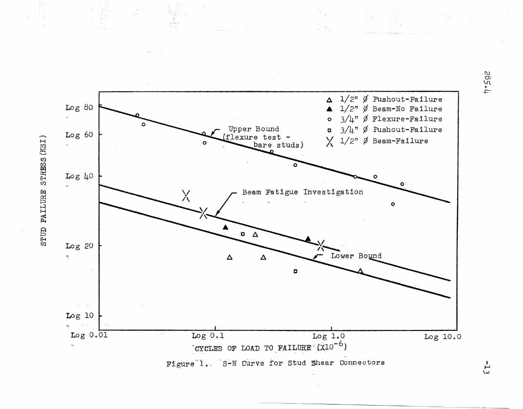
" Betam .Des.ignation
Bl & B21 1 -3"5 at 1 1 -3" = 6 t -3 tf4tt
- .. ~ - ... -, {tOt ("j .. - ,'i-"
!fft 6 at 1 1 -0 1/2" = 6'-3 ft 1 1 -3"- - ~ ...
"' ,. '-I ....,) - ',~"..
Sill 7 at 01-10 1/2" = 6'-1 1/2ft If-3 ft:.~ ... - ::::;; -- "' - ---
,f"1, r"l r"',
4ft ... 8 at 0 1 -9 3/8" = 61 -3n- 1 1 -3 TT~ ""--.. -- .. .
,"'..... t tlll"l"lj -
11' Ii 11 TI' 'IT 1rJ (
IIE. 71 -l~" ~ I
If-J
\..n.
Figure 40 Beam Dimensions

18 n
9 ft
:Rocker Support
I\)(X)
\rto
-r=-
sti.ffener
Lab Floor
.Hinge Support
nistributor Beam (6117025)Flate and Grout
Hydraulic Ja.ck
Composite Specimen12WF?7
Floor
7"
stiff'ener
t-6 tr
15' -o"n
Figure 50 'Test setup
IJ-J0'