Embed Size (px)
Citation preview

Welded C0nti1nl.1JO~lS Frames and Their Components
Progress Report Noo 31
ROTATION CAPACITY REQUIREMENTSFOR SINGl,E-SPAN FRAMES
by
George C. Driscoll, Jr.
fl?l'f l EI\1.GI1\1 EEnH\JG',aABORl\TO~l\r i.Jr;r~/~r·JY
This work has been carried out as a partof an in.'\res tigation span,Bored jointly by the Weld,c,in.g Research' Counci.l and the Departluent of the Navywith funds furnished by the following:
Americ.an In.stltute of Steel Con~t..:ruction
American Iron and Steel InstituteInstitute of Research, Lehigh UniversityOffice, of Naval Research (Contract NOIlr 61003)Bureau of Sh.ipsBureau of Yards f.litl,d Docks
Reproduction of this report in whole or inpart is permitted for any purpose of the UnitedStates Government"
Fri. t2'lEng.ineerin,g LaboratoryDepartment of Civil Engineering
Lehigh University:Bethleh,e.m, Pen.nys 1van.ia
Sep telube.r",· 19 58Fri.tz Laborat.or)T Report. Noo 26805

2.68e5
TABLE OF CONTENTS
1. 0 INTROD-UCTION
2 e DER T~lA.TION OF HINGE ANGLE .EQUATIONS
2.11. Meehan.isms, Domains, and Plas tic Moment Values 0
2." 2 Loca.tion of Fi.rst and Last Plastic Hinges.
203 Hinge Angle Equations o
204 Description of Graphs of Hinge Angle Equations.
205 Derivation of Equations for Deflections
3. ILLUSTRATIVE EXAMPLE- .. GABLED FRAME.
4. PROBABLE E.XTREME VALUES OF HINGE ANGLES·
401 Extreme Values of Loading and Geometry
402 Extreme Values of Hinge Angles 0
5. SUMMARY
6 " ACl<NOWLEDGEMEN1'S
7 0 NOMENCLATURE
8/1 REFERENCES
9. FIGURES
i
page
ii
1
3
3
4
8
15
17
19
24
24
27
30
32
, 33
36
37
'I"
ABS1.'RACT
Plastic analysis of steel structures depends on the ability
of the Ine~mbers t.o form plas ti.c hinges, and to re.di.stribute mome.nts.
In, oordc"r f.or redis tr'ibution of moment to take place, certain plastic
hin.ges 'must sustain. the.i.r plastic moment t.hrough SOllIe angle of rota-
tiouo The amount of rotation required may affect the stability of
the structure an.d therefore, may affect the geometry of the structural
shapes selected and the spacing of lateral bracingo The ability of a
structural member to rotate in order to redistribute moments and form
a mechanism is defined as the "rotation capacity"o The angle of rota-
tion during which a yi.elded segment of beam must sustain its plas~ic
moment value is te.rnled the IIhinge ang~e".
An E~arlie.r report on continuous beams presente.d the equations
and methods of handling the boundary conditions for the calculation of
3the required hinge angles of structures. This paper extends that
work to co·ver the calculati.on of required hinge angles for single"
span portal frames with pinned basesn
ii

268.5 -1
1. INTRODUCTION
Recent developments in the plastic analysis of steel frames
have pres~nted a more rati10nal basis- on '\'Jhieh to. desi.gn "welded coh"tillUOUS
structure,s. Methods based on these developments give promise of econ-
omies to be gained by taking advantage of the reserve of strength o£
structural steel beyond the elastic limit, by using simple methods of
analysis, and by assuring a uniform factor of safety against failure
2for all structures~
Plastic analysis of steel structures depends on the ability
of the Inembers to form plastic hinges and to redistribute moments. In
order for redistribution of moment to take place, certain plastic
hinges must sustain their plastic moment through some angle of rota-
tion~ The amount of rotation required may affect the stability of the
structure and, therefore, may affect the geometry of the structural
shapes selected and the spacing of lateral bracing. The ability of
a structural member to rotate at or near its plastic moment is de-
fined as rotation capacity. The angle of rotation during which a
yielded segment of beam must sustain its plastic moment value is
termed the required "hinge angle".
I this paper deals with the calculation of the approxitnate
l1inge angles required to allow mechanislTIS to fortn in single"span
gabled portal frames with pinned bases. The development of the basic
method of solution is presented in an earlier paper on three-span
3beams~ There, it is shown that calculations of rotation and deflec-
cIon may be made, by using modified sloper·deflection equations with

268.5
appropriate boundary conditions 0 The dominant boundary condition is
shown to be continuity at the last plastic hinge to form" The same
basic method of solution will be used in this paper without resorting
to complete development of the method o
Finally, an attempt will be made to determine the maximum
required hinge angles for practical sizes and shapes of frames under
the probable ranges of loading for which they might be designedo
-2
26805 -3
2& DERIVATION OF HINGE ANGLE EQUATIONS
Prior to deriving equations for the required hinge angles, the
proportions of the frames will be stated and the boundary conditions
governing the solution of the problem will be determined o
Ketter 6 has presented equations and charts which permit the
rapid design of single and multiple span frames. This work will be
referred to in order to obtain the required plastic moment for the
various possible mechanisms. The same system of notation will be
fo] 1)r~1ed close1 y ill the development of hinge angle equations.
2 a 1 MECHANISMS:~ DOMAIN~, AND PLASTIC MOMENT VALUES
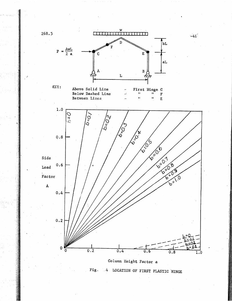
Consider the typical gabled portal frame with pinned bases
shown in Figo 10 The frame has a span L, a column height of aL and a
roof rise bLo The special case of a flat roofed frame is obtained
when b equals zero. Rolled structural shapes of constant cross section
are assumed. A uniformly distributed vertical load of w pounds per
foot is applied to the entire raof o The effect of all horizontal
forces is represente.d by a load P equal to AwL/2a applied at the to'p
of the windward column.
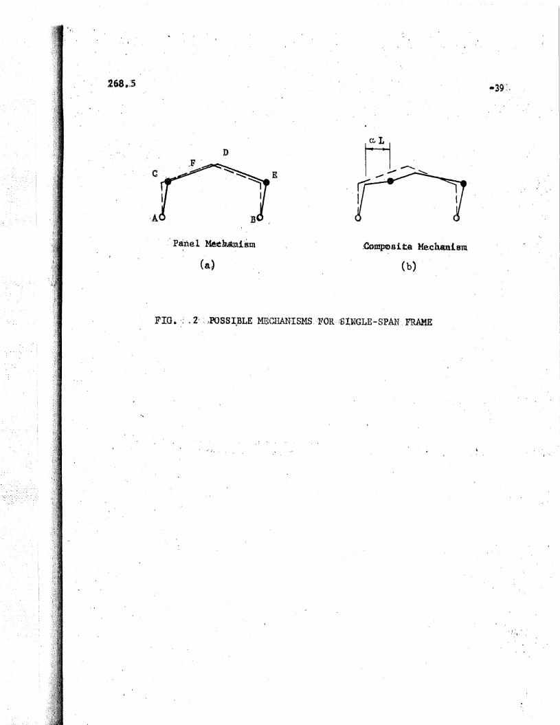
The possible mechanisms which determine the maximum load
of tilis fratue are u sidesway or panel luechanism (Figrl 2a) and a general
composite machanism (Fig. 2b).
For the panel mechanism, the relationship between plastic
6inoment and ul timate .load is:
~ AwL 2 - 4
268,5
The maxinlum load"'ffiomellt expression for the composite mech ..·
anism i,s: 6
whe.r(,
c£ = !~1 c" ~[A (1+~) - ~ -~
or
forE. >0a
bfor == 0
a
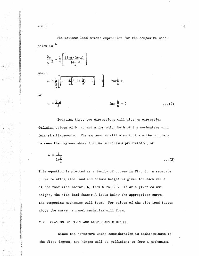
Equating these two expressions will give an expression
defining values of b, a, and A for which both of the mechanisms will
form simultaneously. The expression will also indicate the boundary
between the regions where the two mechanisms predominate, or
A = _1_
1~ "f (3)a
This equation is plotted as a farndly of curves in Figo 3. A separate
curve relating side load and column height is given for each value
of the roof rise factor, b, from 0 to 100. If at a given column
height, the side load factor A falls below the appropriate curve,
the composi.te mechanism will forron For values of the side load factor
above the curve, a panel mechanism will form.
2 u 2 LOCA1'ION OF FIRST AND LAST PLASTIC HINGES
Since the structure under consideration is indeterminate to
the first degree, two hinges will be sufficient to form a mechanismn

268.5
Determi.nation of the locat.ion of the first plastic hinge by means of
an elastic solution will then give the location of the last plastic
hinge by elimination.
Plast.ic hitlges are shown in F~g. 2 to exist only at the
two "1::,',:", ',(;1,8, C and E, and in the windward rafter at F 0 An elastic
solution will give the following values for the moments at these
points.
J:101nentat Windwar d Knee
-5
Me = w~2 [A(F+J)
Moment at Lee l{nee
wL2 [ ]ME = '" -8- AF + G.0 • (5)
causes tension on the inside of the framen The functions F, G, J,
MaximUlll Moment in Windward Rafter
MF= wL2 [1 + 2A + A2 + £ F(A2 ,..A) -AF + E. GA
8 a a
bG - G
1 b2(G + AF) 2]+--
a 4 a2
In the above equations a plus '+) sign designates a moment which
and N are given by:
F = [ ~+ 24 + 12-ab
]11+4.b2 N
... (6)

J =1z4 £ + 16 b2J[a a2.
N I"~ 8a + 12 + 12£ + 4 b2J= ~1+4b2 a a2
Equations 4 through 7 are derived from superposition of two cases
given in Ref. 5. The substitutions F, G, J, and N have been made
-6
to reduce the bulk of the equations, and the load parameter A has been
added.
Because hinge E is common to both mechanisms, the problem
of location of first plastic hinge reduces to finding when Me and MF
By equating Me and ~ME and making the substitutions in Eqo 7,
the following boundary between first plastic hinge at E or at C is ob-
tained:
8 ~~ S£.A:::: 8_
12£ + alia a 2
for b > 0
... (8)
When b=O, the f1.rst hinge cannot. occur at c.
Another limit on the first hinge at E is the occurrence of
an equal or greater elastic moment at F. The boundary for this case
is obtained by equating MF and -ME-

268.5 -7
22F + £ G + l ~ FG)
a 2 a2
for b > 0~ 0 • (9)
A 1 '0 2\f_l-2a+3
for b :::: 0
Equation (8) is plotted as a family of solid curves
passing t4rough the origin in Fig. 40 The region above the curve
for a giyen value of the roof rise factor b, represents the values
of A and a for which the first plastic hinge will form at the wind~=>
ward knee Co Below the curve, "the first hinge will form at the lee
knee En
Equations (9) and (10) are also plotted in Fign 4, as a
family of dashed curves, These curves divide the values of A and
a for which the first plastic hinge will form at a point F in the
windward rafter, from the values for which the first hinge will
form at the lee knee, E. It will be noted that the first hinge
can form in the rafter only for small values of b, the largest
being about OG387, "7hen the column hei.gllt is no gre.ater than the
frame span,
Figso 5 and 6 are charts showing the limits of mechan-
isms for b values of 0, and On2 respectivelyo On these charts, a
shaded area above, the line representing Eql> (3) denotes the frame
sizes and loadin.g for which a pan,el mechani.sm will occur, while
thEl cle,ar area, indicates the general composi te me.chan.ism. An
addi.tional lin.e in the shaded area representing Eq. (8) separates
268.5
the regions in whi.ch the first plastic hinge will form at the windward
knee C or in the lee knee E. A final line in the unshaded area sepa=
rates the region in which the first hinge forms at E from the region
in which the first plastic hinge forms in the rafter at F. This curve
re.pr~sel)t's Eqo (9) or (10) as applicable.
It may be seen from Fi.g. 5 that a panel or sidwsway mech···
anism will not occur in a flat-roofed frame with the proportions and
loading considered in this studyo From Eq. (3) it will be seen that
L:he panel me~hanism could occur ~,,111en A exceeds 1.0 n
2.3 HINGE ANGLE EQUATIONS
Derivation of equations for hin.ge angles of single span por~,'
tal frames is accomplished through the use of the ~lope-deflection
equation~3
-8
•.• (11)
9NF = Slope of near end of member
8'NF = Slope of near end of similarly loaded memberwhen simply supported
RNF
= Rotation of a chord between ends of member
= Deflection of one end of a member with respect to theother divi.ded by the distance between thent = 4.£
£ = Length of member or portion of member
MNF = Moment at near end of member
MFN = Moment at far end of member
For cases with sloping roofs, the 9 1 term is expressed in a manner
¥J1],i ch. tak.es in.to accou.nt t.he slan.t of tIle roof. For sytmuetrical

gabled roofs where the dimensions are measured as shown in Fig. 1
the expression is:
-9
~, __ WiJu3 ~~cr 24Ei ~ 1+4~, .•. (12)
:.ithe horizontal projection of the ,length of a segme,ntll
'.rhe sign cOl1vcnti,on used here is tllllt slope nngleA are
defined as pasi tive when the rotations are clockwise, and end momen'ts
are defined as positive w~en acting in the clockwise sense. (see Figo 8).
o with appropriate subscript is used to represent the slope
on both sides of a hinge locationn H, the hinge angle, is used to
represent the difference in, slope at a plasti,c hlnge when the maxituum
load is first reached.
The ultimate load mome.nt diagram for t.he frame is shown in
Fign 7a with the effect of each type of force kept separated.
Case 'Io Comeosite Mechanism"-First Hinge at Lee Knee E
The first solution will be that for the general composite
type of mechanism with the first plastic hinge at the lee column top
(E)~ The boundary conditions for this solution are the continuity at
joints C and D. At Jo:I.nL: E" the slope will be dlscollti.nuous. Substi ..
tuting the moment values from Fig. 7a, in Eq. (11), will form two slope
equations for each member. Since there is ~o transverse load on the•
columns, tha~ 9' terms for those members do not exisio Pertinent lengths
for use in the slope-deflection equations are given in Fig. 7b.
The end slope equations for each m~mber as as follows:
-10
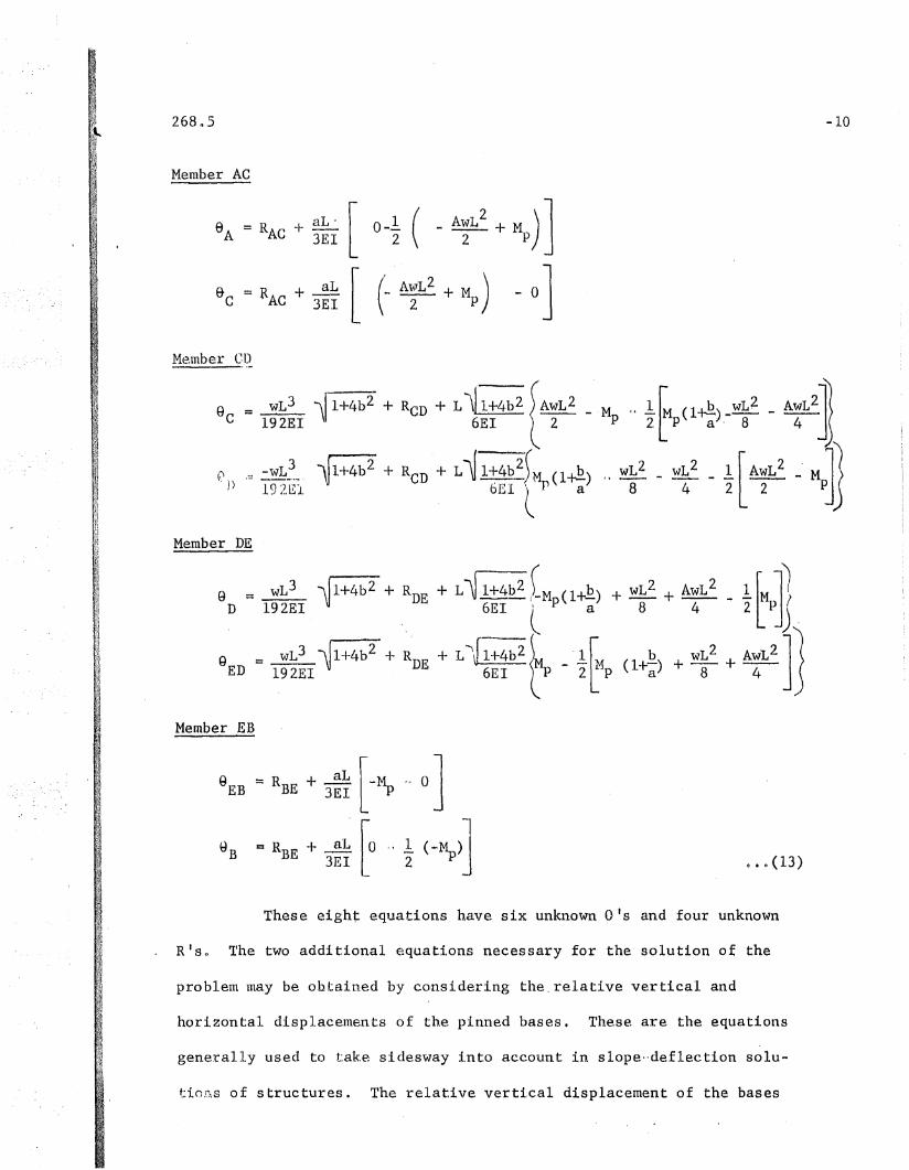
Member AC
SA = R + aL' [ 0 -1. ( _ AwL2
+ M )]AC 3EI 2 2 P
9 = R + ~~ [ ('- .AwL2 + M) .. 0]C AC 3E1 2 P
Me.tuber CD
9C
= wL3 ~ 1+4b2 + RCD + L\!1+4b2 ) AwL 2 _192EI 6EI t 2
(~I) .'-' -wL~_ ll+4b2 + RCD + L\f 1+4b:)M (l-r.!!.)1921'.:1. bEl (p a
Member DE
M c, 1:.~ (l-r.!!.) _wL2 - AWL2JTI
P 2[P a' 8 4 ~
" wL2 _ wL 2 _ 1 [AWL2 _ Ml~8 4 2 2 PJJ
Member EB
= RBE + 3:~ [-~ L' 0 ]
c RBE
+ aL 10 " 1 (-M )]3EI L 2 P ~.~(13)
These eight equations have six unknown a's and four unknown
R'so 'fhe two additional eq"uati.ons necessary for the solution of the
problem may be obtained by considering the. relative vertical and
horizontal displacements of the pinned bases. These are the equations
generally used to tak.e sldesway i.nta account in slope"deflec tion solu-
ti,OD.S of structures. The relati"e verti.cal displacement of the bases

?.68 0 5
is zero and is obtained by multiplying the chord ,rotation R of each
member by the horizontal component of its length and summing these
for the structure.
-11
ReD b + R b = 02, DE 2
The relative hori.zontal displacement of the bases is obtained by
summing the products of the chord rotations R and the vertical
components of the length of each member. Since positive rotations
of Ult-:,llib::\;:s DE and EB cause negative displacelnents of the base B, the
signs of these terms change~
Solution of the ~uations (13), (14), and (15) for OED
and 9EB gives the following:
== ~bb2 ~ (3-Jl. ~)6EI [P 2 a
== L~1+4b2l (-3-~ E.6EI [-p 2 a
The hinge angle at E is equal to the difference in 0EB and OED'
HE == L~1+4b2 IMp ("l"-ab ," 1. b2)+ wL2 (-1. + .2. ~\+ AwL2 (1 ~_\lb)~
EI l 3 a2 12 96 aj 4 8a~
In n.on.-dimensi,onal form, t.his equation is:
• n • (16)
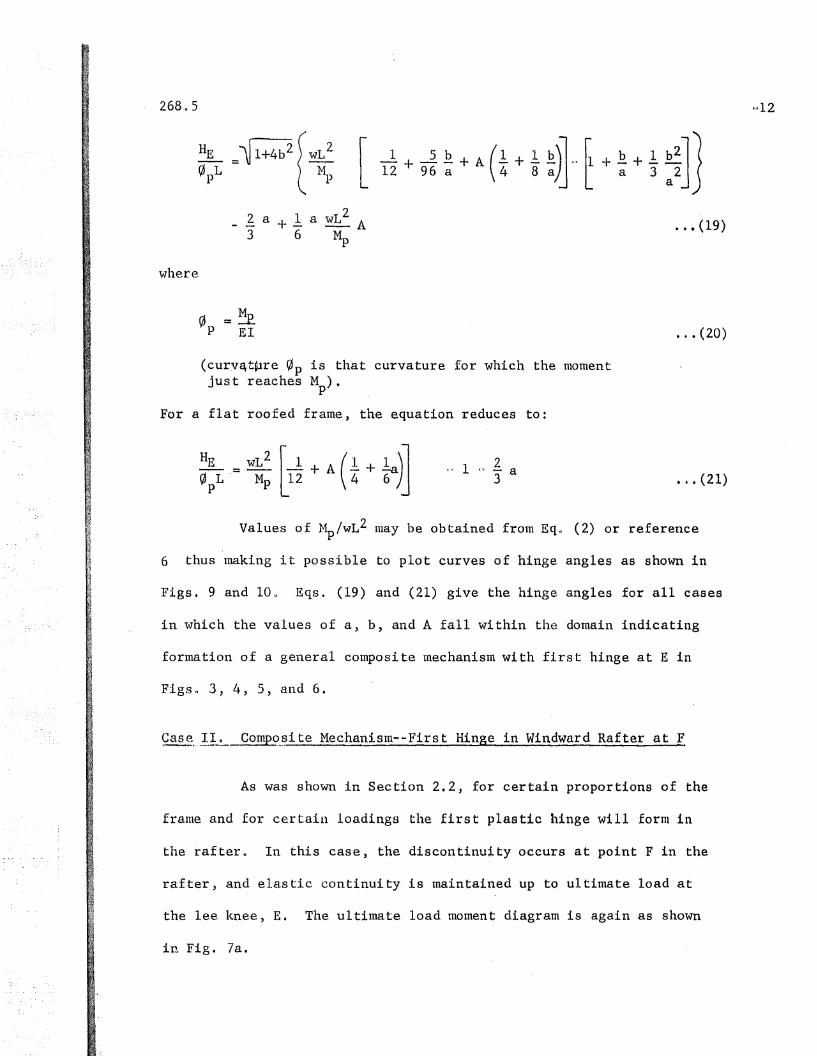
••• (19)
268.5
wllere.
[ 1; + 9~ ~ + A (t + ~ ~)J"r+ ~ + ~ :~J}_ l a + 1. a wL2 A
3 6 ~
~ =~P EI
(curv~t~re ~p is that curvature for which the momentjust reaches M ).p
For a flat roofed frame, the equation reduces to:
•.• (20)
2.. 1 ", - a3 •.• (21)
Values of ~/WL2 may be obtained from Eqo (2) or reference
6 thus making it possible to plot curves of hinge angles as shown in
Figs. 9 and 100 Eqs. (19) and (21) give the hinge angles for all cases
in which the values of a, b) and A fall within the domain indicating
formation of a general composite mechanism with first hinge at E in
Figs~ 3, 4, 5, and 6.
~..!Io Comp~~ite Mechanism--First Hinge in Windward Rafter at F
As was shown in Section 2.2, for certain proportions of the
frame and for certain loadings the first plastic hinge will form in
the rafter o In this case, the discontinuity occurs at point F in the
rafter, and elastic continuity is maintained up to ultimate load at
the lee knee, E. The ultimate load moment diagram is again as shown
in Fig. 7a.

26805
In setting up the slope-deflection ,equations for this case,
it is necessary to write two equations for each of the segments CF and
FD of member eDD Besides the slopet~deflection equations, two additional
equations are again derived from considering the horizontal and vertical
componen,ts of the movement of base B equal to zero o For the vertical
di,splace.ment, this equation is:
-13
For the horizontal displacement the equation is:
D •• (22)
o .~(23)
Solution in the same manner as for the previous case re-
sults in the following equation for the hinge angle, HF :
HF =----~ L
P
+l"l+4b2 wL2
~
Note that the second factor of the product in Eqo (24) is equal in
1l1agnitude to Eq. (19) n When Eqo (19) and (24) are both zero, HE
equals HF' and both plastic hinges form simultaneously, with zero
hinge angle requiredo
For flat roofed frames,
.~ 1 - ~ a3

268.5
In Eqo (24), ~ is the parameter giving the horizontal distance
~L from joint C to the plastic hinge F in the rafter. Values of ~ may
be ob~ained from Reference 6 or the equation,
-14
ct = ~ [~1 " ~ [A (l +~) ,,,11a • · · (26)
Equations (24) and (25) give the hinge angles only for those
cases in whicll a) b, and A fall in the dOluain indicated in the appro'~
priate Figso 3 to 6.
Case la. Panel Mechanism,,-First Hinge at Lee Knee E
For cases where the loading and dimensions are such as to
make the value of a equal to zero, the rafter hinge occurs at the
windward knee and a panel mechanism results. In the usual panel mech-
anism, the first hinge occurs at the lee knee, E, and it is there that
the hinge angle is required.
The ultimate load moment diagram for the panel mechanism
is the same as for the composite mechanism (Fig.7a) with the special
L\"quirements that ct equal zero and Eq. (1) hold for ~/WL2. Therefore,
making these substitutions in Eqo (19), the resulting expression for
the hinge angle is~
For flat roofed frames, Eq. (21) reduces to:
1=-3A
••. (27)
•• ,,(28)

Eqsa (27) and (28) give the hinge angle at the lee knee, E,
for a panel mechanism when a, b, and A fall within the proper domain
of Figso 3 to 60
Case IIa. Panel Me,chanism,·,-Firs t Hinge at Windward lSnee C
Certain gabled frames as shown in the domain Figs. 4 and 6
luay fortn a pan,el Ine.chanisln wi th tIle firs t plas tic llinge a t the wind ..
ward knoe Ca This is a special condition on Case II where the value
of ~ equals zero so that point F is at point C. All results of Case
11 at point F become equal to the corresponding results for point C
when ~ is set equal to zero and Eqo (1) is substitutued for M /wL2 op
The hinge angle at joint C then becomes:
-15
For flat roofed frames, it is impossible for the first plastic hinge
to occur at joint C as shown by Eq. (8)0
Though Eqo (29) is :Ldentical to Eqo (27») it Il\USt be borne
in mind that they usually apply to different values of a, b and A, and
thus the values of He and ~ will coincide only when Eqo (8) is satis""
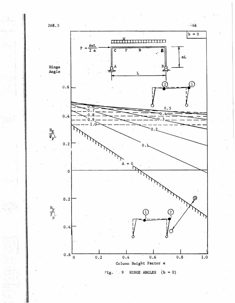
204 DESCRIPTION OF GRAPHS OF HINGE ANGLE EQUATIONS
Graphs of the hinge angle function are plotted for two values
of the roof rise factor b. Figure 9 presents the hinge angles for
frames with flat roofs (b~), and Fig. 10 the hinge angles for gabled

frames with roof rise factor b = 002. Each of the graphs shows the
nOllodiluensional magni tude of the hinge angle (H/~pL) plotted versus
the column height factor, a. These hinge angle curves are plotted
for values of the side load factor A ranging from 0 to 1.O~ The line
for A = 0 is hatched, indicating the initial value of the functiono
Initial.Ly, only values of H on and above this lin,e are valid. With
increasing side load, the sloping lines indicating the hinge angles
for larger values of A gradually move upward and decrease in slopeo
When the value of A reaches about 0.5 for flat roofs and On3 for
b = 0.3, the hinge angle function begins to decrease with increasing
values of side load factor A.
With the aid of small sketches of the mechanisms on each
graph, the controlling plastic hinge and equation may be identifiedo
The major portion of each graph is that part' above the abscissa which
gives values of the hinge angle, HE, at the lee knee representing
Eq. (19) and (21) for the composite mechanism o A slnall sketch of
the composite mechanism adjacent to that area indicates that the
first hinge farIns at the lee knee and the second hinge in the wind-
....n::.l'ci portioll cd.: Lhy: roof member 0 CO'iuparable sketches ido,nti.fy the
portions 0 f the graph c,oIIlprislng the () ther cas es. Addi tiollal values
of HE occur wi th a panel Inechanislu Wllich occurs at high side loads.
For flat roofed frames the panel mechanism is denoted by A = 1.0 and
greater (Eqo 28). For gabled frames, results of Eq~ (27) appear be
low the, dashed line in Fig. 10 and above the abscissa.
For the gabled frames in Figo 11 the hinge angle curves for
A = 0.5 to 1.0 drop below the abscissa at the left side of the graph.
-16
t.
268.5
These are the result of Eqo (29) for the hinge angle, He' at the wind
ward knee in a panel mechanism.
One more area of importance appears in each graphn This is
the area bounded by the A = 0 line below the abscissao In this region,
wi th '. ·.l"Y light side loads and longer columns) the firs t hinge forms
in the windward rafter at F with a composite mechanism resultingn The
values of ,HF
are calculated from Eq. (24) and (25). Many practical
cases may be covered by this region because of the absence of side load~
2.5 DERIVATION OF EQUATIONS FOR DEFLECTIONS
From the same solution which results in the equations for
hinge angles, the horizontal deflections of the kn,ees and the vertical
deflection of the ridge may be derived.
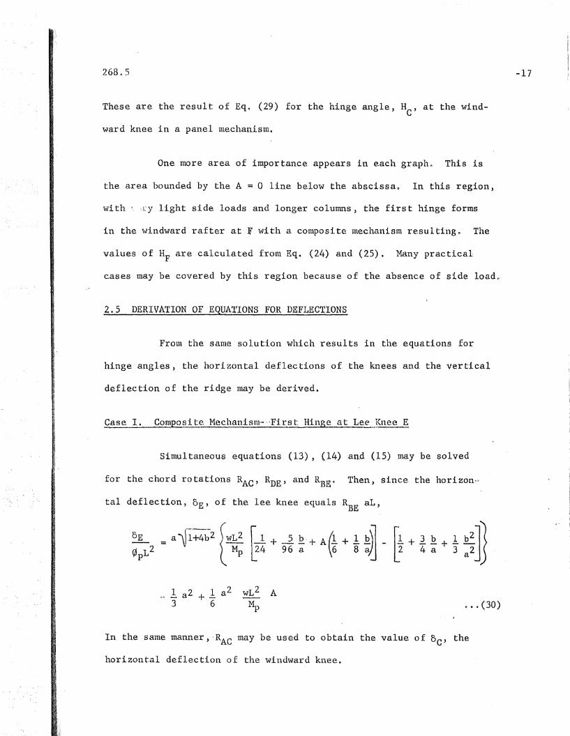
Case I. Composite Mechan,isnl-"Fi.rst. HInge at Lee !(nee E
Simultaneous equations (13), (.14) and .(15) ,may be solved
for the chord rotations RAe' RDE , and RBEn Then, since the horizon,-·,
tal deflection, 0E' of the lee knee equals RBE
aL,
-17
1 2 1 a 2_ a +_3 6 o •• (30)
In the same manner, ,RAe may be used to obtain the value of DC' the
horizontal deflection of the windward knee.

268.5 :-18
1 a 2 wL 2 A6" M;
Sine,-, :te vertical deflection, DD' of the ridge equals ,. R L/2,DE
~~on
=" 1+/fb2
(_5 + ~A) _ (1 + ~ £)]o L2 384 32 8 12 a
p'00 0 (32)
Similar methods give equations for deflections for all the
cases~ These are summarized in the appendix of reference 20
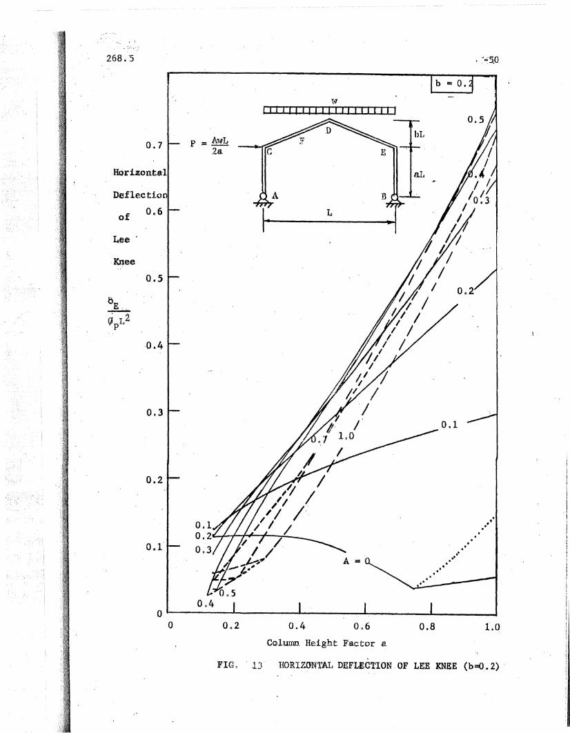
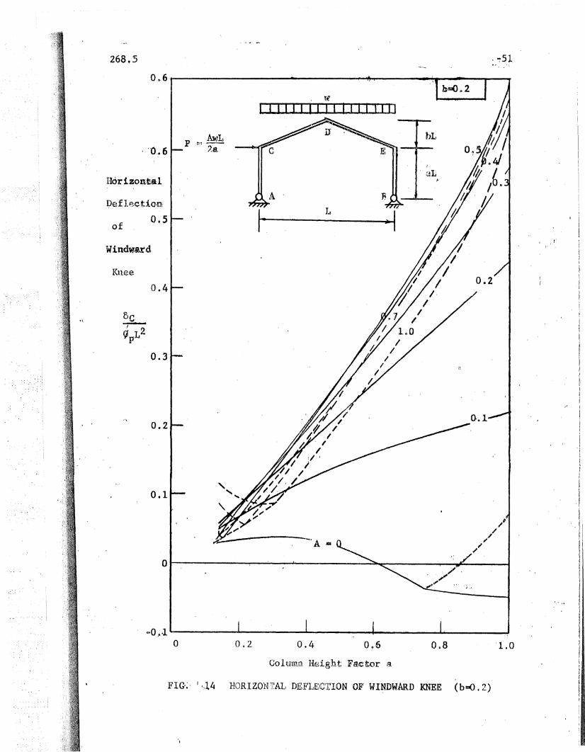
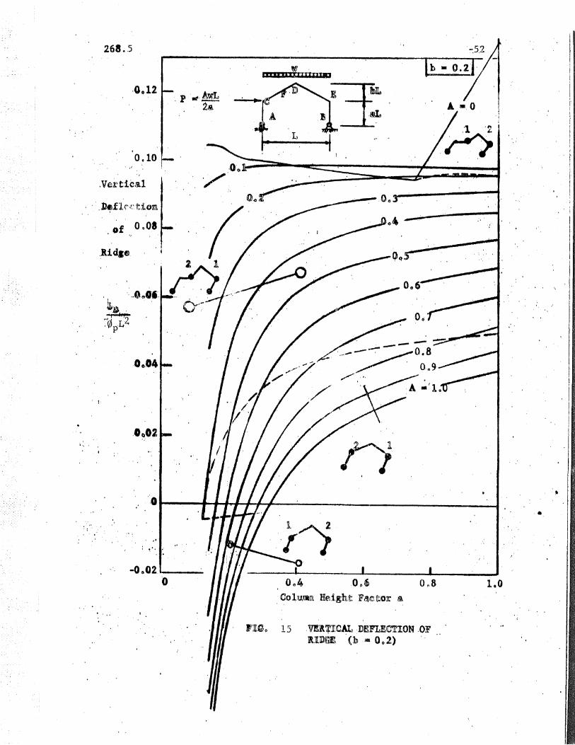
Graphs of deflections are plotted in Figso 11 through 150
In each graph, a deflection function 5 is plotted against column
height factor, a, for a number of side load factors, Ao
Figs~ 11 and 12, give the horizontal deflection of the knees
and the vertical deflection of the middle of the beatn for flat-roofed
frameSn Figs. 13 and 14 give the horizontal deflections of the two
knees of gabled fratnes (b =0.2), wIllie Fig. 15 gives the vertical' de"
:<1,':':1.' Llc.I'n of Lhl..~" r'i.dges of gabled fruliH:,:;S-j
The style of the deflection graphs is the same as that of
the hinge angle graphs described in Section 24. There should be no
particular difficulty in reading ,the graphs.

268.5 ~19
3. ILLUSTRAll IVE .EXAMPLE'·;-GABLED FRAME
The equations derived here make it possible to determine the'
hinge angles required to form a mechanism as well as the deflections
of joints of a large variety of portal frames. The equations will
serve Lor all synnnetrical frames with pinned bases as long as the loads
may be approximated by uniformly distributed vertical loads. The ef·"
fect of horizontal loads is replaced by a concentrated horizontal ,load
at the eaves of such magnitude as to cause the same moment about the
base, Use of the results of this study will be illustrated by an ex-
ample of a gabled frame which wi.ll be compared with experimental re-
sultS(l
Given: Span length, L = 40 ft.
Column height, aL 10 ft.
Roof rise bI, 8 ft.
Bent spacing s c: 17 ft.
Vertical working loads:
Horizontal working load:
Dead plus live,plus snow
Wind,
Load factors:
60 pafn
20 psf
Dead plus live load, 1.88Dead plus live plus wind load 1.410y' 33 ksiE, 30,000 ksi
Find: Rolled structural shape for the frame.
Hinge angle required to form a mechanism.
Deflections at maximum load.
268.:1
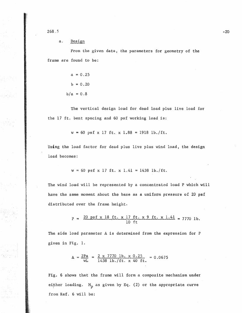
Design
From the given data, the parameters for geometry of the
frame are found to be:
b/a = 0118
The vertical design load ,for dead load plus live load for
the 17 ft. bent spacing and 60 psf working load is:
W := 60 pst x 17 fto, x 1.88 = 1918 lh./ft.
Using the load factor for dead plus live plus wind load, the design
load becomes:
-20
w = 60 psf x 17 fto x 1041 1438 lb./ft.
The wind load will be vepresented by a concentrated load P which will
have the same moment about the base as a uniform pressure of 20 psf
distributed over the frame height o
p = 20 psi x 18 ftc x 17 ft. x 9 ft. x 1.41 c 7770 lb.10 ft
The side load parameter A is determined from the expression for P
given in Fig. 1.
A = 2PawL
= 2 x 7770 Ib e x 0.25 = 0.06751438 Ibo/ftll x 40 ft.
Fig. 6 shows that the frame will form a composite mechanism under
ei~her loading" ~ as given by Eqo (2) or the appropriate curve
from Ref ll 6 will be:
when A = 0 and
1), = 0.0532 wL2
when A := 01>0675
The section modulus required,without wind is
Mz.= -..E. := 0,0456 x 1.918 k/ft. x 40 ftl>x 12 x 40 in.0y 33 ksi
= 50.8 in3
The section modulus required with wind is:
Z = 0.0532 x 10438 k/ft x 40 ft x 12 x 40 ino33 ksi
The case without wind controls.
Section economy tables will give a 14 WF 34 with Z ~ 54.5 in3 .
However, in the event delivery on 14 WF 34 could not be obtained, or
for some reason it was desired to use a shallower member, a 12 WF
36 ~vi. th Z = 51.4 in3 would suffice. The 12 WF 36 member will be
selected for this example.
bb Hinge Angle and Deflections
The hinge angles and deflections for this frame are given
in Figs. 10, 13, 14, and 150 Entering ,the charts with b = 0.2,
a = 0025, and ,A = 0, the following values are obtained:
Front Fig 0 10
-21
268.5
From Figo 13
From Fig.1 14
Fronl Fig. 15
by substituting the known values for ~p and L, these functions may
be evaluated as follows:
~pL =MpL = 33 ksi x 51.4 in,3 x 480 in,EI 30 x 103 ksi x 280.8 in4
= 000966 rad.
.-··22
cJ pL2= 46.4 in.
HE c: 0 CI 62 ~pL ::; 0 n060 rad.
0E = 0.117 0pL2 = 5.43 in.
0e =0.036 cJpL2 = 1.67 in.
oD = 0.1005 0pL2 = 4.66 in,
Co Comparison with Experimental Results
Test results are available for a 40 ft. span gabled frame
with 12,WF 36 Inenlbers. 4 rfhis frame was loaded witll four vertical
concentrated loads and had fixed ,bases and a ,slightly different roof
slope, but was similar enough to allow the hinge angles to be compared.
The moment diagrams for the two frames are plotted in Fig. 16 showing
tIlls similarity. The lee knee of the test frame rotated through a
1neasured angle of 0.077 radians at the end of the test with the frame

26805
still at maximum load as compared with the 00060 radian requirement
for the theoretical frame. Of course a small part of this measured
rotation was due to bending ,of the members in the length spanned by
the rotation indicator and should qat be included in the comparison
of hinge angles. This amount was calculated as approximately 0.005
radiars. This result indicates that the theoretical frame would pro
bably be satisfactory just as the test frame-was.
The vertical deflection of the test frame just as it .reached
maxi ::,lCirn load WHS 503 inches as compared wi th40 57 inches required for
the theoretical frame 0 However, the test frame was'able to sustain
the max~mum load through a total deflection of 9.9 inches.
Due to the fixity of the bases and the smaller roof slope
of the test frame, it is not surprising that the total horizontal
deflections of the knees were less than those theoretically required
for the pinned~base frame. The experimental deflections were 3.9 inn
for the l~e knee and lD6 for the windward ,knee as compared with 5.43
a.nd 1067 respectively, for the theoretical pinned··base frame.
-23

268.5 -24
4. PROBABLE EXTREME VALUES OF HINGE ANGLES
401 EXTREME ,VALUES OF LOADING AND GEOMETRY
Since one of the primary objectives of this study is to
determine extreme 'values of the hinge angles) some attention will
be given to the extreme ranges of the factors controlling hinge
angles. In the proceeding sec tiona it hus been shown that a franle
may be designed and the magnitude of the required angle determined
if the following factors are known:
(1) Span length, La'
(2) Bent spacing, s
(3) Column 'height, aL
(4) Roof rise, bL
(5) Vertical load intensity, w.
(6) Horizontal concentrated load, p = AwL/Za
studies was limited to the values given in Table 10 A detailed
description of how each of the values in Table I was selected is
The first four factors are geometric factors which are
generally controlled by architectural considerations. The last
two factors are the load factors which are determined by the de'-~
sign allowances made to take care of dead load, live load, and wind
loado An estimate of the probable range of each of these variables
in typical rigid frame designs was made on the basis of various
structural and architectural discussions in available literatureG 5 ,7,
8, 9)' 10) 11 From this estimate, the range, of variables to be
g:i-Vetl in Ref 0 2.
268~5 -25
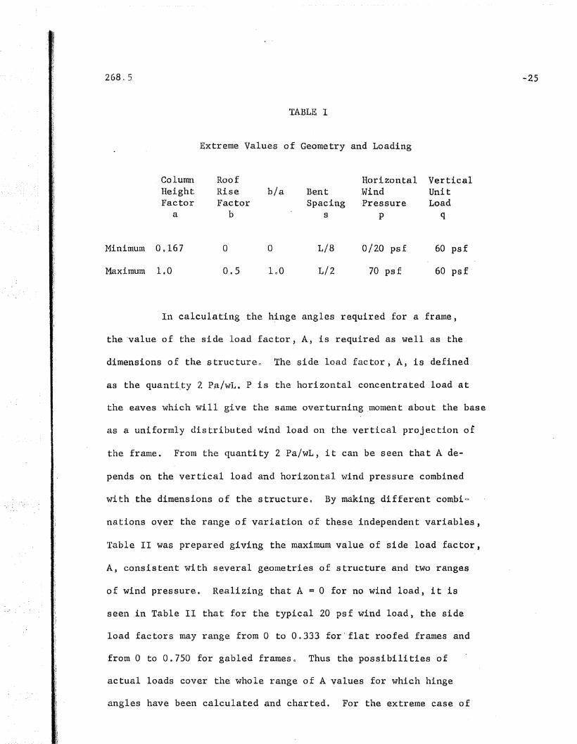
TABLE I
Extreme Values of Geometry and Loading
Column Roof Horizontal Vertical",
Height Rise b/a WindBent UnitFactor Factor Spacing Pressure Load
a b s p q
Minimum 00167 a 0 L/8 0/20 psf 60 psf
Maximum 1.0 0.5 100 L/2 70 psf 60 psf
In calculating the h~nge angles required for a frame,
the 'value of the side load factor, A, is required as well as the
dimensions of the structuren The side load factor, A, is defined
as the quanti~y 2 Pa/wL. P is the horizontal concentrated load at
the ,eaves which will give the same overturning ,moment about the base
as a uniformly distributed wind load on the vertical projection of
the frame. Franl the quantity 2 Pa/wL, it can be seen that A de-
pends on the vertical load and horizontal wind pressure combined
with the dimensions of the structureo By making different combi~
nations over the range of variation of these independent variables,
Table II was prepared giving the maximum value of side load factor,
A, consistent with several geometries of structure and two ranges
of wind pressure. Realizing ,that A = 0 for no wind load, it is
seen ,in Table II that for the typical 20 psf wind load, the side
load factors may range from 0 to 00333 for" flat roofed frames and
from 0 to 0.750 for gabled frames 0 Thus the possibilities of
actual loads cover the whole range of A values for which hinge
angles have been calculated and charted. For the extreme case of

268,,)
a 70 psf wind load, ItAII-values less than laO will include all
structures except those with the largest column heights. For the
cases with long colunms, it is probable that the hinge angles will
be smaller than the values plotted for A = 1 and at least an upper
bound for the hinge angles is included in the curves", (Fig~ 10).
TABLE II
Maximum Values of Side Load Factor A
Wind Load Column Roof MaximumHeight Rise Side LoadFactor Factor ,Factor
a b A
Flat Roofed Frames
20 psf 0.2 0 GnOl333
005 0 . 000833
1.0 0 0 0333
70 psf 0.2 0 o ~ 0467-
OQ5 a 0.292
1.0 0 Inl66
............~ ...
Gubled Frames
20 pst 002 002 0 0 0533
005 005 OQ333
loa 0.2 00480
1.0 005 oQ750
70 psf OQ2 O~2 001867
005 0.5 1.167
100 002 1 0 680
11\0 0.5 2.62"I
to- .... .11 ~ " I .... ~ .. 1IIo~ .-
-26
26805 -27
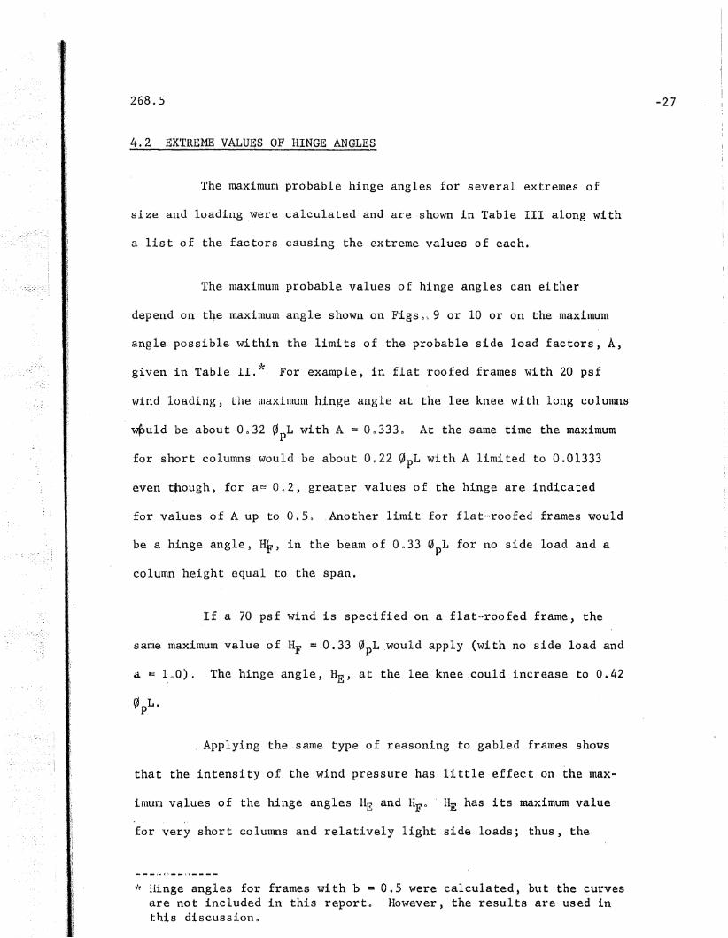
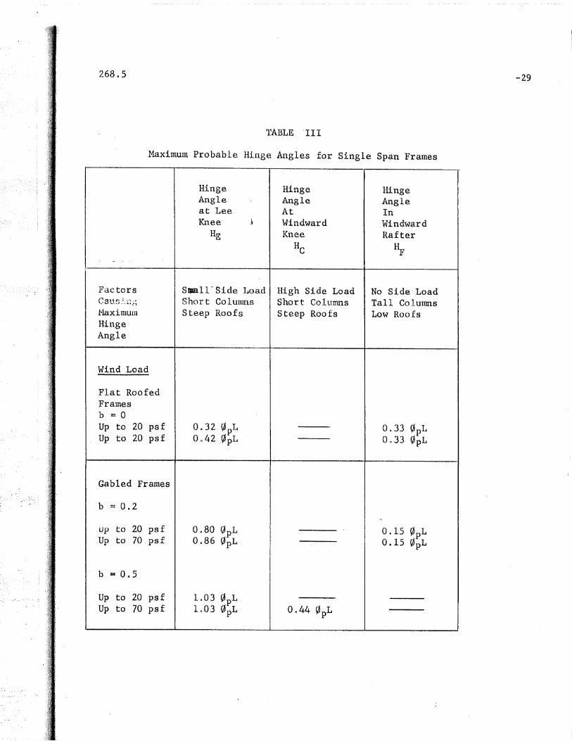
4.2 EXTREME VALUES OF HINGE ANGLES
The maximum probable hinge angles for several extremes of
size and loading ,were calculated and are shown in Table III along with
a list of the factors causing the extreme values of each.
The maximum probable values of hinge angles can either
depend ,on tQe maximum angle shown on Figso~ 9 or 10 or on the maximum
angle possible within the limits of the probable side load factors, A,
given in Table 11.* For example, in flat roofed frames with 20 psf
wind luading, the luaximUlTI hi.ng~ angle at the lee knee wi th long columns
wPuld be about 0 0 32 ~pL with ,A = On333o At the same time the maximum
for short columns would be about On22 ~pL with.A limited to 0.01333
even tpough, for a~ 0,,2, greater values of the hinge are indicated
for values of A up to 0.5 Q . Another limi t for flatt=>roofed frames would
be a hinge angle, aF, in the beam of On33 ~pL for no side load and a
column height equal to the span.
If a 70 psf wind is specified on a flat"roofed frame, the
same maximum value of HF = 0.33 ~pL .would apply (with no side load and
a == ~,~O). The hinge angle, HE' at tIle lee knee could increase to 0.42
,~ L.P.
Applying the ,same type of reasoning to gabled frames shows
that the intensity of the wind pressure has little effect on the max-
imum values of the hinge angles HE and HFo . ~E has its maximum value
.'for very short columns and relatively light side loads; thus, the
* Hinge angles for frames with b = 0.5 were calculated, but the curvesare not included in this reporto However, the results are used inthis discussionfl

268.5
greater sidelbads actually mean a decrease in required hinge angle.
The hinge angle HF in the rafter has its maximum value with no side
load and with the longest columns and flattest roofs. One additional
factor is introduced in gabled fraules - this is the possibility of a
hinge an,gle He at the windward kneel> The maximum angle occurs with a
high wind load on a frame with short columns and a steep roof.
By picking the extreme values of hinge angles from Table ·III,
it is seen that the maximum hinge angle at a lee knee would be about
1 ,03 Vi pL for a steep gabled frame l) (b = 0 '15, a = 0 n 5, A = 0 0 1). The
maximum hinge angle for a windward knee would also occur in a steep
gabled frame, (b =O~5, a = 005, A c 1n17) with a value of about 0.49
~pL. The maximum hinge angle in the rafter would occur with a flat
roofed frame and w~uld be 0.33 ~pLo (b = 0, a = 1.0, A = 0)0
rJ~ABLE .I I I
,Maximum Probable Hinge Angles for Single Span Frames
Hinge Hinge HingeAngle Angle Angleat Lee At InKnee ! Windward .Windward
HE Knee RafterHe ~
_..
;
Factors Sul1·· Side J~oad High Side Load No Side LoadCaus .~.,r~~_:~ Short Colunms Short Columns Tall Colunms'IvIaxinlulIl Steep Roofs $teep Roofs Low RoofsHingeAngle
Wind Load
Flat RoofedFramesb = 0Up to 20 psf 0.32 ~pl. 0.33 ~pLUp to 20 pst O~42 ~pL On33 0pL
Gabled Frames
b = 0.2
up to 20 psf 0.80 QpL 0.15 ~pL.Up to 70 psf 0.86 YlpL 0.15 0pL
b 1:1 Oil 5
Up to 20 psf 1003 V1 pL,Up to 70 psf 1n03 VlpL 0.44 ~pL
-29
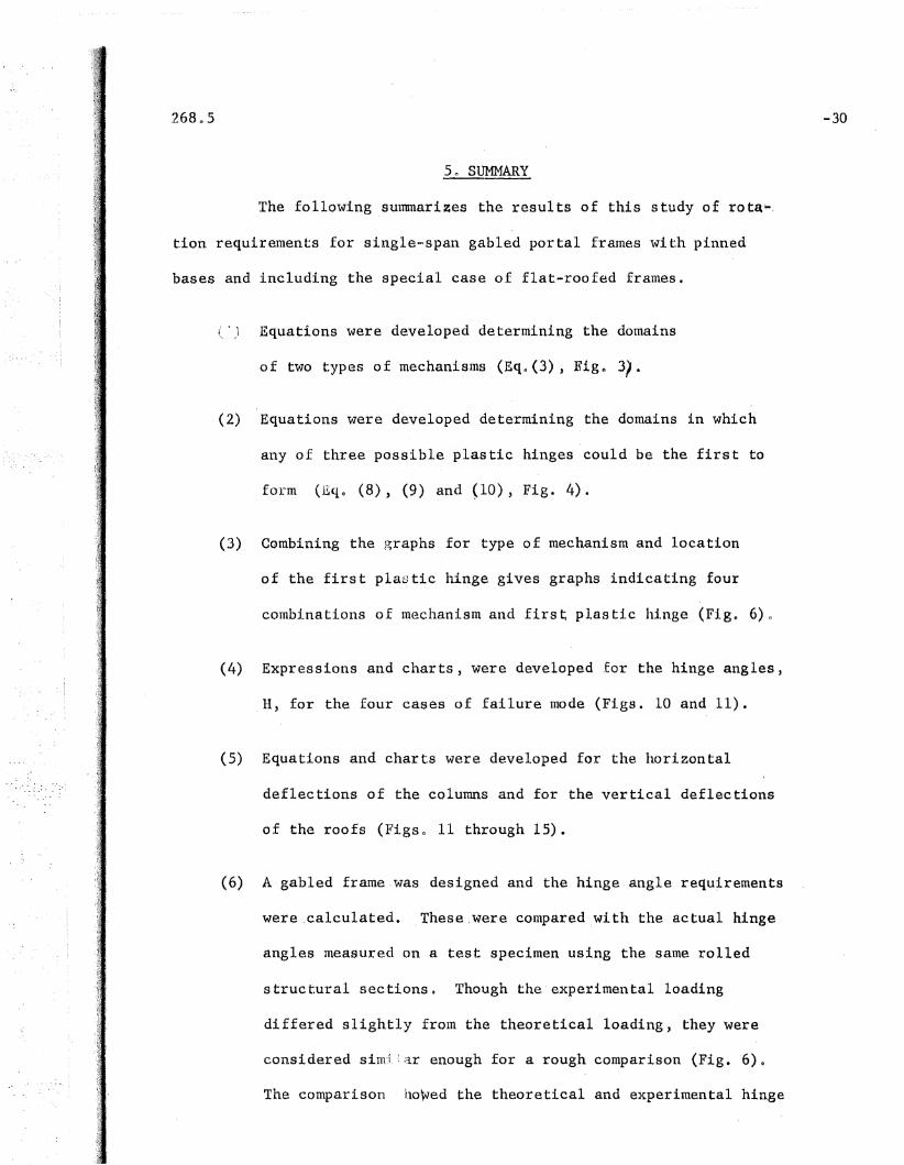
5 n SID1MARY
The following sUlnmari~es the results of this study of rotaN,
tion requirements for single-span gabled portal frames with pinned
bases and including the special case of flat-roofed frames.
(') Equations were developed determining the domains
of two types of mechanisms (Eqn(3), Fign 3).
(2) Equations were developed determining the domains in which
any of three possible plastic hinges could be the first to
form (Eqo (8), (9) and <10), Fig. 4).
(3) Combining the graphs for type of mechanism and location
of the first plastic hinge gives graphs indicating four
combinations of mechanism and first plastic hinge (Fign 6)~
(4) Expressions and charts, were developed for the hinge angles,
H, for the four cases of failure mode (Figs. 10 and 11).
(5) Equations and charts were developed for the horizontal
deflections of the columns and for the vertical deflections
of the roofs (Figso 11 through 15).
(6) A gabled frame.was designed and the hinge angle requ~rements
were.calculated. These.were compared ,with the actual hinge
angles measured on a test specimen using the same rolled
structural sections 0 Though the'experimental loading
differed slightly from the theoretical loading, they were
considered simJ:ar enough for a rough comparison (Fig. 6)0
The comparison hawed the theoretical and experimental hinge
-30

angles to be of the same order of magnitude 0
(7) The maximum possible hinge angles were determined for a
complete range of frame proportions and for wind loadings
ranging from zero to 70 psf, including the usually speci
fied wind load of 20 psfo These calculations showed the
maximum hinge angle at a lee knee to be about 1.03 ~pL
for gabled frames with small side loads, short columns and
steep roofs o The maximum hinge angle at a windward knee
would be about 0044 0pL for gabled frames with large side
loads, short columns, and steep roofs. The maximum hinge
angle in a beam or rafter would be about 0033 ~pL for flat
roofed frames with tall columns and no side load.
The method of solution used in this report has also been
adapted to the solution of rotation requirement problems for multi·~
span frames. Later reports will present the solutions for flat-roofed
and gabled multi-span frames with pinned baseSD
-31
6. ,ACKNOWLEDGEMENTS
The author wishes to express his appreciation for the helpful
sugges tions and cri ticisms made by several of the research personn'el
at Fritz.Engineering Laboratory during the development and preparation
of t.h," \,~To-rk presented in this paper. Dr. Robert Lo Ketter was espe
cially helpful in lending the full use of his calculations on the
plastic design of frames. Le Wu Lu check~d the theoretical derivations
and carried out many of the numerical calculations for the resulting
The analytical work described in this report is part of a
project on 'Welded Cont:t.nu()us Frames and Their Components"!, being
carried out under the directi.on ofLynn S. B'eedle. The project is
sponsored jointly by the Welding Research Counci 1 an,d the U0 S. Navy
Department unde~ an agreement with the Institute of Research of Lehigh
Universi ty _, Funds are supplied by the American Ins ti tute of Steel
Construction, American Iron and Steel Institute, Office of Naval
Research, Bureau of Ships, and the Bureau of Yards and Docks. The.
work was done at Fritz ,Engineering Laboratory of which Professor
.William J. Eney is Director.
-32
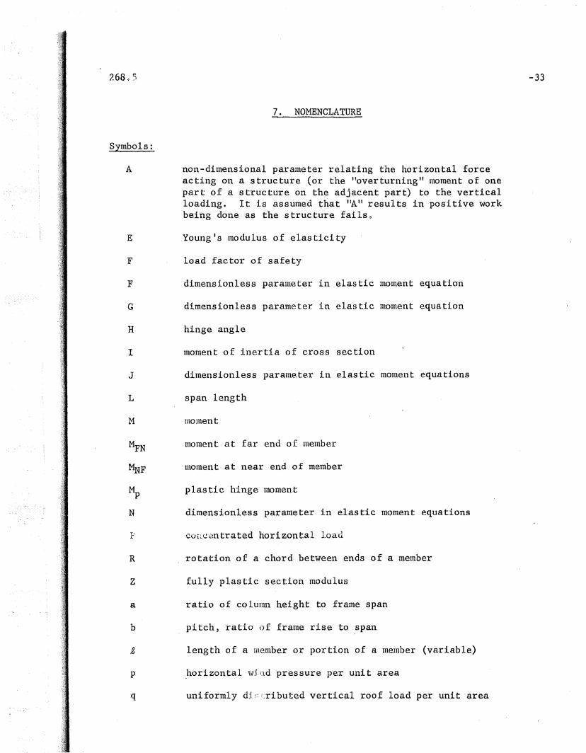
7. NOMENCLATURE
Symbols:
A non-dimensional parameter relating the horizontal forceacting on a structure (or the "overturning" moment of onepart of a structure on the adjacent part) to the verticalloading. It is assumed that ItA" results in positive workbeing done as the structure failsn
E YOUIlg'S modulus of elasticity
F load factor of safety
F dimensionless parameter in elastic moment equation
G dimensionless parameter in elastic moment equation
H hinge angle
I moment of inertia of cross section
J dimensionless parameter in elastic moment equations
L span length
M mOluent
MFN moment at far end of member
MNF "moment at near end of member
Mp plastic hin.ge momen.t
N dimensionless parameter in elastic moment equations
P corLcentratedhorizontal load
R rotation of a chord between ends of a member
Z fully plastic section modulus
a ratio of column hei.ght to frame span
b pitch, ratio of frame rise to span
p, length of a 1l1ember or portion of a menlber (variable)
p .hori zantal w:L rld pres sure per uni t area
q uniformly d:t i.ributed vertical roof load per unit area

2.68:.5 ..
s
w
bent spacing
uniformly distri,bu~ted load per unit length of span
non=dimensional parameter defining the distance to t4elocation of the plastic hinge in the rafter of a structurea
deflection
slope or rotation of a member from undeformed shape
yield stress of steel
curvature of member
curvature parameter Mp / E[
displacement
-34
Subscripts in Slope-Deflection Equations:
Single letterDouble letter
First letterSecond letter
Important Functions for Frames:
jointnletnbernear endfar end
DC ' horizontal deflection of windward knee
On vertical deflection of ridge or center of flat roof
DE 'horizontal deflection of lee knee
,He hinge angle. in windward kn.ee
Hn hinge angle at ridge
HE ,hinge angle. in le.e knee
HF hinge angle in wi.ndward rafter
Definitions:
Plastic Hinge A yielded section of a beam which actsas if it were hinged, except that it hasa const~rit restraining momenta

268.5
Hinge Angle
Rotation Capacity
Mac\J,ani s nl
Plastification ofcross section
Redistributionof lfument
The required rotation of a given plastichinge in a structure that is necessaryto assure that the structure reaches theul timate load.
The ability of a structural member torotate at near-maximum momento
,A system of members (and/or segments ofmembers), that can deform at constant load o
It is used in the special sense that allhinges are plastic hinges (except pin ends) 0
The development of full plastic yieldof the cross sectiono
A process in which plastic hinges formsuccessively in a redundant structure ~~.
until the ultimate load of the structureis reached. In the process, a new distribution of moments is achieved in whichportions of the structure ,which are lesshighly-stressed in the elastic state subsequently reach the plastic hinge valueoRedistribution is accomplished by rota~
tion through the hinge angle of earlierformed plastic hinges.
-35
268_5 -36
1. Beedle, L. S.t'hur limahu , ~lr.Ketter, R.. L.
2. Driscoll, G. t., Jr.
3. Driscoll, G. C., Jr.
4. Driscoll, G. C., Jr.
5. Griffiths, J •. D.
6. Ketter, R. L.
7• Knudsen" l{. E.Schutz"Fo W.Beedle, L.· S.
8. Korn, M. P.
:",1 • Sh~,~dd, T If G.
10.
11.
8. REFERENCES
PLASTIC DESIGN IN,STRUCTURAL STEEL1955 Summer Course Lecture Notes,Lehigh University""'-AISC 1955.'
ROTATION ,CAPACITY REQUIREMENTS FORBEAMS AND FRAMES OF. STRUCTURAL. STEEL,PhoD. Dissertation, Lehigh University,1958.
ROTATION,CAPACIIY REQUIREMENTS FORCONTINUOUS BEAMS, to be publishedin ASeE Proceedings 0
l.'HE PLASTIC BEHAVIOR OF Sl'RUCTURAL.MEMBERS AND FRAMES, Progress ReportNOQ 21, Welded Continuous Frames andTheir Components, The Welding ,Journal,Research Suppl., June 1957, page 275-8
SINGLE 'SPAN RIGID FRAMES IN STEEL,AISC, 19480
PLASTIC DESIGN OF MULTI-SPAN RIGIDFRAMES, PhoDo Dissertation, LehighUniversity', 19560
PROPOSAL FOR THE CON11NUATION ,OFPORTAL FRAME TESTS, Fritz LaboratoryReport 205D.4 (Unpublished).
,A SHORT COURSE .IN WELDED RIGID fRAME.DESIGN, The Welding Journal, 36(3),p 236-239, March 19570"
31lRUCTTJRALDESIGN IN STEEL, JohnWiley & Sons, Incb' 1934.
STEEL CONSTRUCTION, ~nerican Instituteof Steel Co~struction Handbook
NATIONAL BUILDING .CODEi, National Boardof Fire Underwriters, 1955, p 111, 272.
26805 -37
Fig. 1.
2.
3.
!.,..,
5.
6.
7.
8_
90
IOn
11.
12 0
130
14~
15.
16.
9. FIGURES
Frame Dimensions and Loading.
Possible Mechanisms for Single-Span Frame.
Type or Mechani.S1l1
Location of First Plastic Hinge
Limi ts of Mec,hani.sms (b 9 0)
Limits of Mechanisms. (b,= 002)
(a) VI tilnate Load Momen.t Diagratn(b) ,Lengths of Members
Nomencla~ure for Slope-Deflection Equation
Hinge Angles (b = 0)
Hinge Angles (b ~ 0.2)
Horizontal Deflection of Khees (b = 0)
Vertical Deflection of Beam (b = 0)
Hori,zontal Deflection of Lee Knee (b' = 0.2)
Horizontal Deflection of Windward Knee (b := 0.2)
.Vertical Deflection of Ridge (b =0.2)
Comparison of Moment Diagram for Theoretical Exampleof Gabled Frame with MOment Diagram for ExperimentalTest of a Gabled Frame 0

.... - .
'."
,. \'I
"
bL
, ElL
(
L
jl I'
..
II c_taIl",
, . lip GClllt.amt. '
'.
.'
~ .
./
: ,
P AwL8lTa',.
. : ~t:' t'
, ,.
'.
'I. ' ...
2680.5
D
',' Panel Me~Mrmi8m
(a)
,ContprDsite. Mechanism
(b)
.' I j
FIG. ': ~ 2" :, ,lPOSSI.BLE MECHAN,ISMS, 'FOR,.IS~WGLE-SPAN'. FRAME
• . ,I l ~I j •
"

-,40,'
1.0
L
O~4 006 0.8Column Height Factor a
I iii i ; Ii' , W, ; I , , ! I .• , I .
Fig. .3. TYPE OF MECHANISM
. p =~2 a
0.2
26805
Below ,Curve Above Curve1.0
b = oJ
= 0,1
0,8.2
0.3Side0.4
Load0.6 O.
·d.Factor
A
1.0,4
First Hinge C" fI FII If E
006 0.8 1.0--
Column Heigh.t Fa.c tor a
Fig l' '. 4 LOCATION OF FIRST PLASTIC 'HINGE
Above Solid. LineBelow'Dashed LineBetween Lin.e~s,
. wI I J I I} I I I I I I I J I I I I I I I
p :: AWL2 a
1,0 ~--~_--:"'_--'------r-----r---~:----~---t
o 0
0.6
q.8
0.4
"fillY:
A
Side
Load
Factor

. C3.42
l. b = 0
L
~ \\1
~II' I11II I rrrrrllllJ' J
p = AW~L_~w-r;::========~2 11
00 0 0 2 ,O~4 006 0.8 1.0
Column Height F4ctor a
Figll 5 LIMITS OF MECHANISMS (b = 0)
0.2 -
0.4

1.0
I b = 0.2 I-43
First~inge
F
FirstHinge
E
Shad.ed Area
Column Height Factor a
. ToT ''.1 I I I I I I I I I I , I J I .1 I 1 J I
PIs.in Are.a
".,,/
(jI
FirstHinge
C
p =~2 a
Fig 0 r) LIMITS OF MEClID1ISMS (b = 0.2)
1.0
0.8
o 0
0.2
A
Side
Load
Factor 0.6
26D.5

aL
bL
"~44
, ,aL "
E
B
I),
-:--------t-------~B
~l ~ ~) --f-._L_/_2__~Flg & Q ib 0 LE~tG1'HS OF MEMBERS
I'(~=CYJ) rl~;~\F
F
A
L
'17FIGo~8.(l tTLTJMATE I1)J\D Mll1ENT JJIAGRAM
M (1+2Ed)P a
C~----------t---+--
A ,.--..-__~__............,

268.5
= -~24EI
-45
Fig. 8 Nomenclature for Slope-Deflection Equation
N F
b = 0
. ;:'46
at
A=O
II 1115 I I I 1 I 1III I I I I I I
'p =~ ---......~r===========;:;,,Z a C F D I......
o
0.4,-
0.2
H'E~pL
HlngeAngle
268~.5
0.6 0 0.2 O~4 0 .. 6 ,0.8 '
Colunin Height Factor a
1.0
F~g. '. '9' HINGE ANGLES (b = 0)

',I,
"
1.0
D
-A=O
.C F
'0 0 2- . 0 p 4; 0 n 6
Column He~ght Factor a
" I
O.---...--.....--.II~------a.~.......-:l...__.............. ....... ....--Io "
,FIG. ~ 11 HOltIZONTAL DEFLECTION .OF KNEES (b=O)
DeflectiD10l
~ ,0. 7
.. . .0,0,4
O~2
0.3
·lIlees
.Horizontal
268. '5'i

l.O
bL
aL
L
Colmnn H~ight F~ctor a
Fig 0 ",10 HINGE ANGLES (b=O 0 2)
p = AWL,2. a
1.06
HiI~g(.,
Angle ',104
.ln2
'HaCI .L . 1.0 '
p,
O~8Aq)o
0.6
00'4
• 0.2
0 ,A=Oo ~
A=Q.5HF 0.2 -~
~ L':p. '
0_4
, A=O. 7
0.6 .-- Aa=() II 8
'He Ar:zO 09
~ L 0<,8 A=lo0p..
1000 0.2
.,

1;0b.s·OQ4 O~6
ColuDm Height Factor a
I I I I I I I I I I I I ii' I I J I I I
to F D E
\rJ,:l.'1
A B
I~L
A =·0 .
@ CD
0.2
FIGo l~~ VFll1'ICP,L DEFLECTION ,OF BEAM (b=O)
- - 0.6- -- --- - -' -...- - .-..'-_.-...
- ..-. OoS - - -- --.. - - - - - - '--' - -
o
- -;-;-.;-;-w •.....-.A-& •....:..: :..... • tJ •
........-----..~--- A == w---..."....:..:. - -- - - A = 0.4
",_T,
~49
- '- - 009 - - ""'""'- - - -...- - - - - -
-- 100 -- - - - - - - - - -...... -, ---
01----.......""-~........_-..........----.....-----...................--_ _I
--Oco7-- -
, ~ - - - 0':18 '- - - --O. (' 5
0.02
0.03
·0.10
,0.16
Vert~cal
Deflection
of 0.14
,Beam
, .- ...': i I ....., ~,~.
· ~~5.0
I .
1.q0.8
..........-..-..'...' ......
bL
A =
L
0.4Column Height Factor a
I I I I I I , I I I I I , r I I I 1 I I I
FIG 0 '13" BORIZON1~ DEFLECTION, OF LEE KNEE (b=O 0 2) .
p = !:!:!Jd.'2.a
o"'----........------------.........---_.a.- ....o
of
0.5
0.7
Deflection
,HOrizonta-1.
.Knee
.,. t'
'1.0
0.2
hL
, aL'f-
~IJ.JI
0.4
, ---·A ..
, ttrn.....:t..-J...-,I I I I 0 IJ I ID
~,
.1/'
"~",.,: ,/
Ot-----------..j'------~IIoliIp_---._,_.......ll'"__--__I',/ ,
-/";,,. ',.i,,,
FIG<" '.I.,l4 :HORIZONTAlt DEFLEC'fION OF WINDWARD KNEE (hmQ. 2)
CSO"o..l ~ --lL....-. ---Io -+ --.... --,
o
o c. 6+------------------~~----~'!T_.......-__.-....,..~51.
P :=1 A.wL, "0,. 6 ~a
0.4
0.2
0.1
IZn.ee
268.5
I·Yc)rizontal
Windw£rd
-.. ,
A-.O
004 ,00''CO~tUmt1l Hei,ght F$tr.lttor a
, ,JLO(> 15 ,VEll~I.C~ :DEFLECTION ,OFl\IDJGm (lb· 1II 0 0 2)
-.p'.,,~.. '2£
, "
-0 002,"- __o
",0.' .....----.....~r-#-~"-#------- ___. _I
,0 0.04
,O~,02
• I
0010
268 . .5
"
.Vei)t~cal
.,B.id.&,
, ' ,.~fl{~'\t' tion
.of 0.08

l .
268.5
'11 L. , J irn.....
On31L rFJ:,rsJ; H1t1&e
0.20Mp
t._",.~,.......",...~............. '~""""'-------------------"---------i
EXPERIMENTAL G~LED FRAME205.5 T-9
O.26L
RotationMeasured atFirst Hinge
(o.17L..
O.25L
12WF36
FIG ! ,,16 CO~AR.I.SON OlJ" MOMENT DIAGRAM FORTHEORE'flCAL EXAMPLE OF GABLED FRAMEWITH..MOMENT .DIAGRAM FOR. EXPERIMENTALTEST OF A GABLED FRAME