Embed Size (px)
Citation preview
1
1.Introduction
2.Why do we need to consider fracture
mechanics in concrete?
3.Fracture mechanics for concrete
4.Computational Models for fracture
Fracture Mechanics for Structural Concrete
2
What is fracture mechanics?
When a crack length reaches a certain critical length, it can propagate, even though the average stress is much less than the tensile strength of the test specimen.
Fracture mechanics tries to find the quantitative relations between crack length, material’s resistance to crack growth, and the stress at which cracks start to propagate.
Introduction
3
Strength based approach
With classical linear elasticity, we can calculate the stress concentration effect.
However, at the very sharp crack tip, the theory generate an infinite stress.
Evidently, it is nonphysical.
If it is true, the strength will be near zero. Therefore, more rational method needed.
Introduction
4
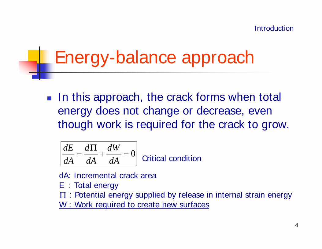
Energy-balance approach
0dE d dWdA dA dA
In this approach, the crack forms when total energy does not change or decrease, even though work is required for the crack to grow.
Introduction
dA: Incremental crack areaE : Total energy
: Potential energy supplied by release in internal strain energyW : Work required to create new surfaces
Critical condition
5
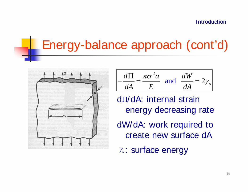
d /dA: internal strain energy decreasing rate
dW/dA: work required to create new surface dA
: surface energy
Energy-balance approach (cont’d)
2
an 2d sd a dWdA E dA
Introduction
s
6
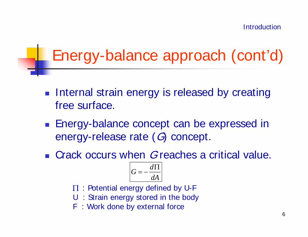
Energy-balance approach (cont’d)
Internal strain energy is released by creating free surface.
Energy-balance concept can be expressed in energy-release rate (G) concept.
Crack occurs when G reaches a critical value.
Introduction
dGdA
: Potential energy defined by U-FU : Strain energy stored in the bodyF : Work done by external force
7
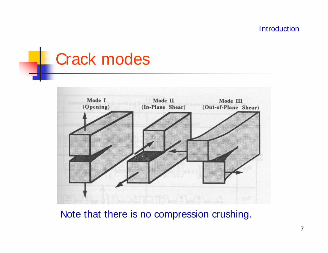
Note that there is no compression crushing.
Crack modes
Introduction
8
1. Introduction
2.Why fracture mechanics in concrete?
3.Fracture mechanics for concrete
4.Computational Models for fracture
Fracture Mechanics for Structural Concrete
9
Formation of cracks require a certain amount of energy, which agrees with the fracture mechanics concept.
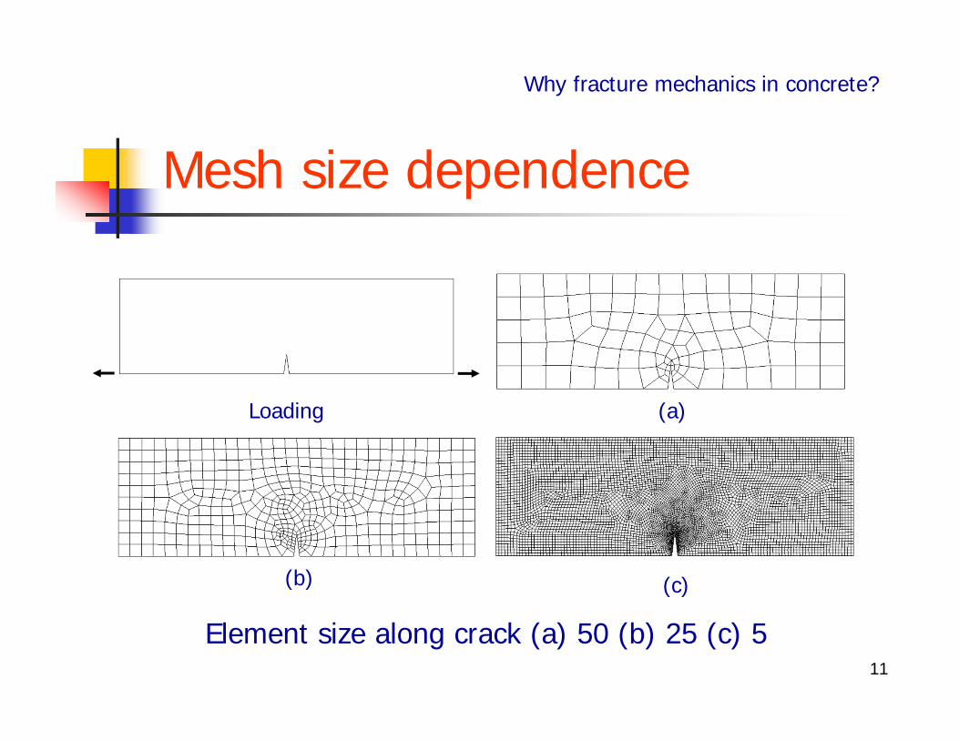
Finite element analysis based on the strength criteria is unobjective around sharp crack, that is, the analysis depends on the choice of mesh size.
Why fracture mechanics in concrete?
Why fracture mechanics in concrete?
10
Limit analysis approach based on plasticity theory cannot be justified in brittle types of failures, e.g., punching shear, shear failure without shear reinforcement, etc.
Size effect can be addressed by fracture mechanics.
After all, tension softening type failure (Quasi-brittle failure) can be tackled by fracture mechanics.
Why fracture mechanics in concrete? (cont’d)
Why fracture mechanics in concrete?
11
Mesh size dependence
Element size along crack (a) 50 (b) 25 (c) 5
Why fracture mechanics in concrete?
Loading
(b) (c)
(a)
12
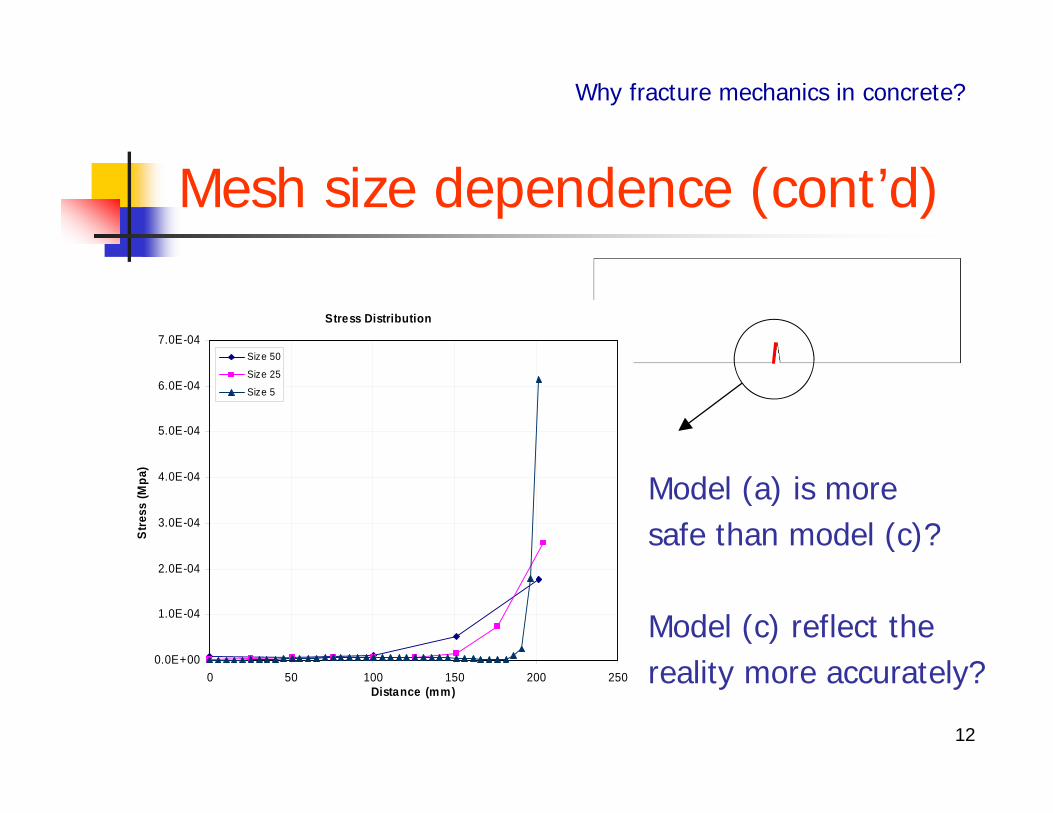
Mesh size dependence (cont’d)
Why fracture mechanics in concrete?
Stress Distribution
0.0E+00
1.0E-04
2.0E-04
3.0E-04
4.0E-04
5.0E-04
6.0E-04
7.0E-04
0 50 100 150 200 250Distance (mm)
Stre
ss (M
pa)
Size 50
Size 25
Size 5
Model (a) is more safe than model (c)?
Model (c) reflect the reality more accurately?
13
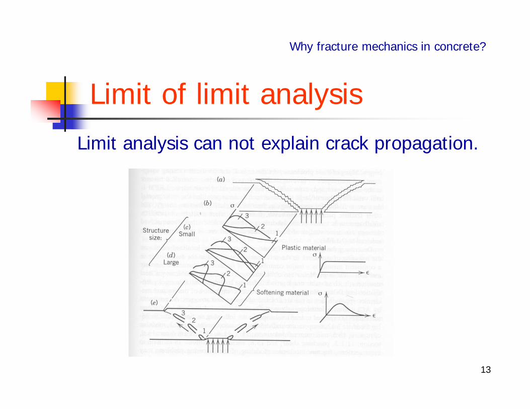
Limit analysis can not explain crack propagation.
Limit of limit analysis
Why fracture mechanics in concrete?
14
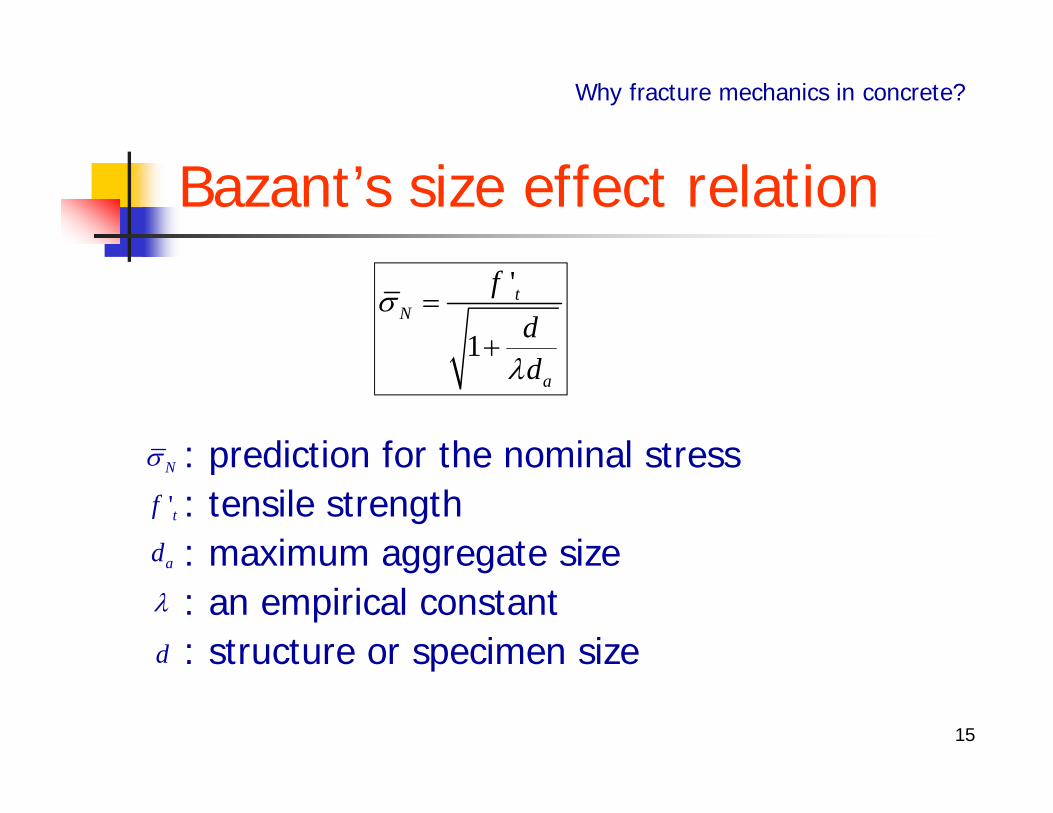
In classical linear elasticity, critical stress does not depend on the structure size.
However, plain concrete shows strong size effect, that is, the cracking stress depends on the specimen or structure size.
Size effect
Why fracture mechanics in concrete?
15
: prediction for the nominal stress: tensile strength: maximum aggregate size: an empirical constant: structure or specimen size
Bazant’s size effect relation'
1
tN
a
fdd
Why fracture mechanics in concrete?
N
'tf
ad
d
16
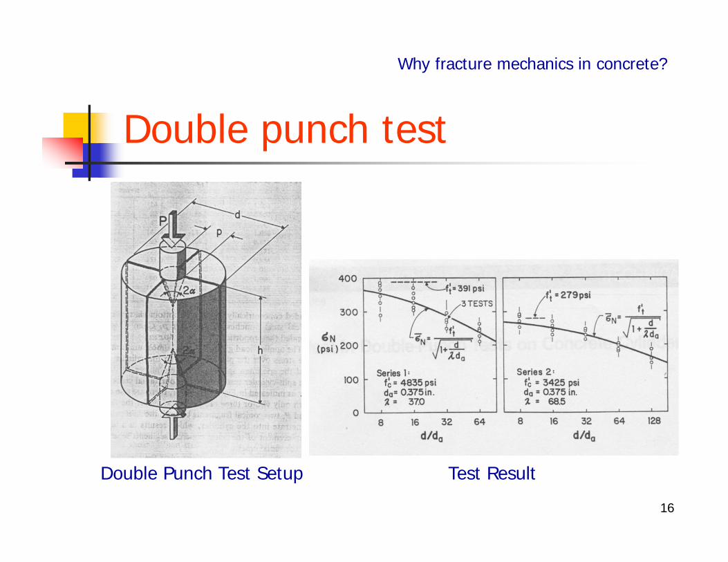
Double punch test
Why fracture mechanics in concrete?
Double Punch Test Setup Test Result
17
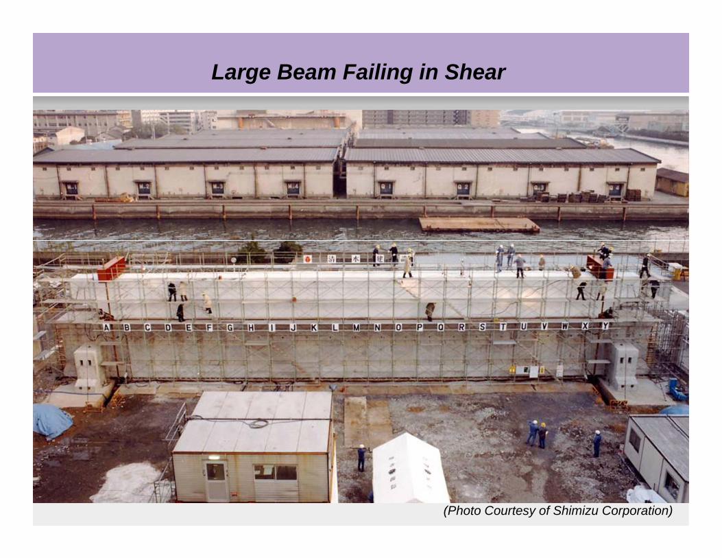
Large Beam Failing in Shear
(Photo Courtesy of Shimizu Corporation)
18
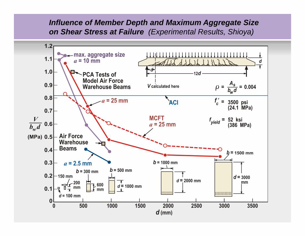
Influence of Member Depth and Maximum Aggregate Size on Shear Stress at Failure (Experimental Results, Shioya)
19
20
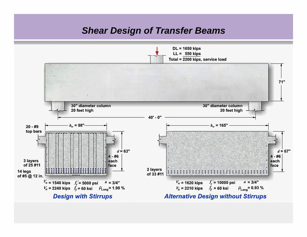
Shear Design of Transfer Beams
21
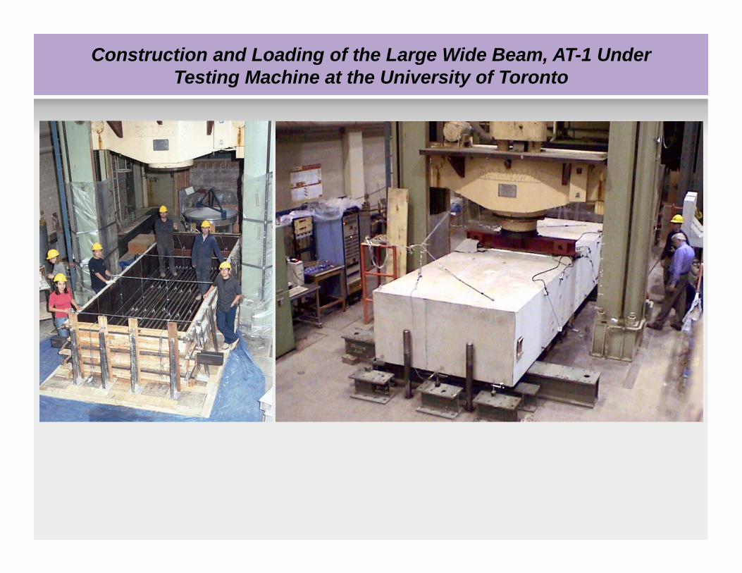
Construction and Loading of the Large Wide Beam, AT-1 Under Testing Machine at the University of Toronto
22
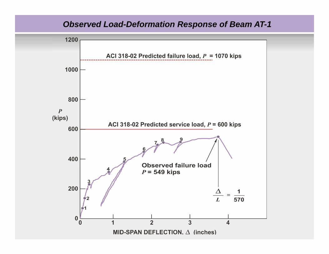
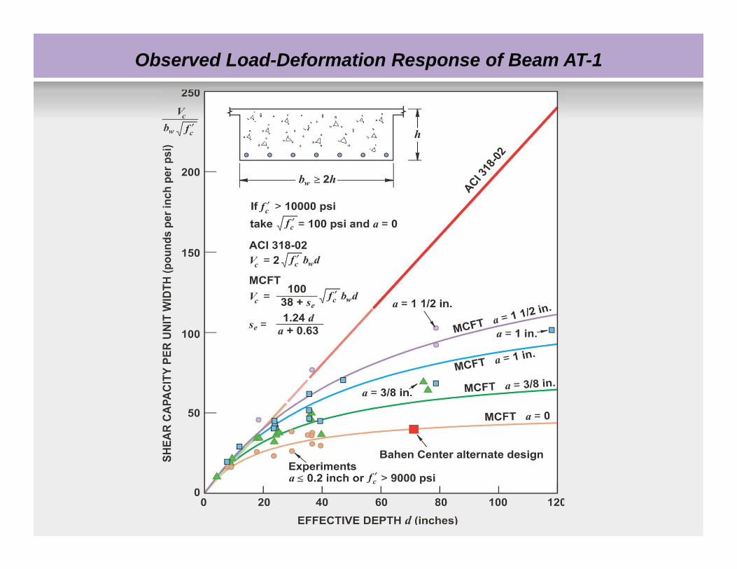
Observed Load-Deformation Response of Beam AT-1
23
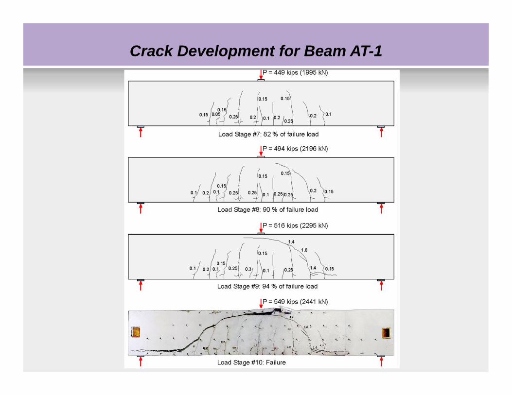
Crack Development for Beam AT-1
24
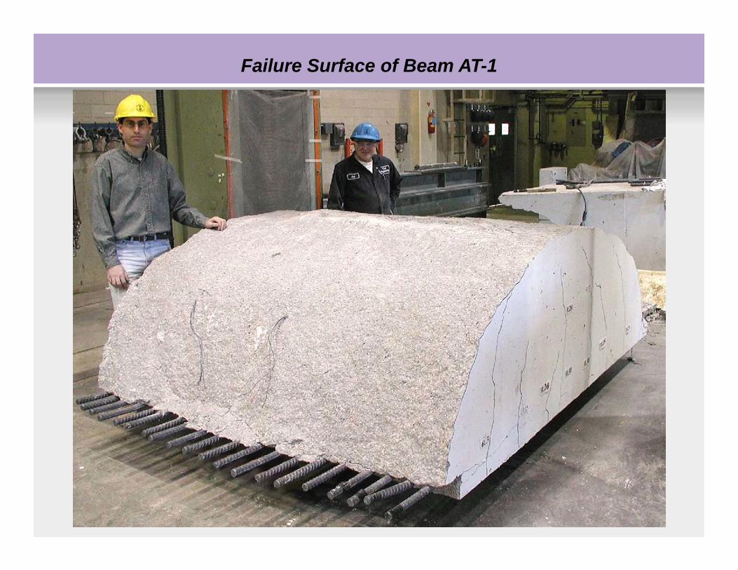
Failure Surface of Beam AT-1
25
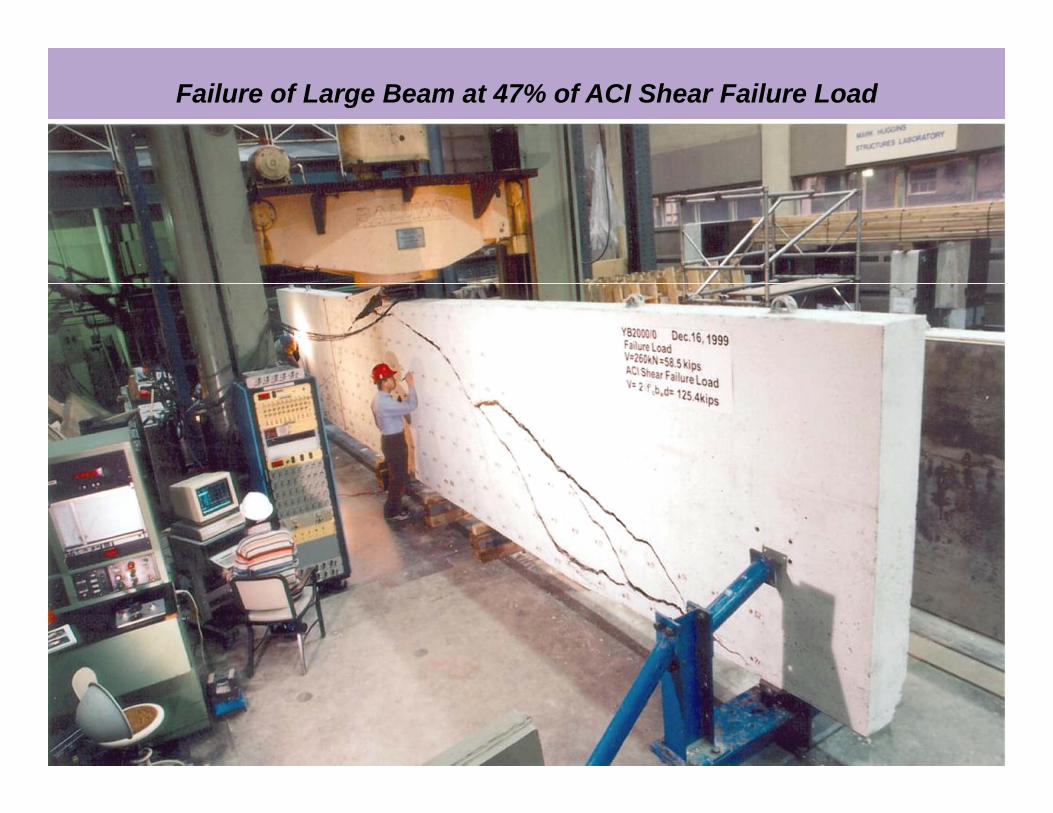
Failure of Large Beam at 47% of ACI Shear Failure Load
26
Observed Load-Deformation Response of Beam AT-1
27
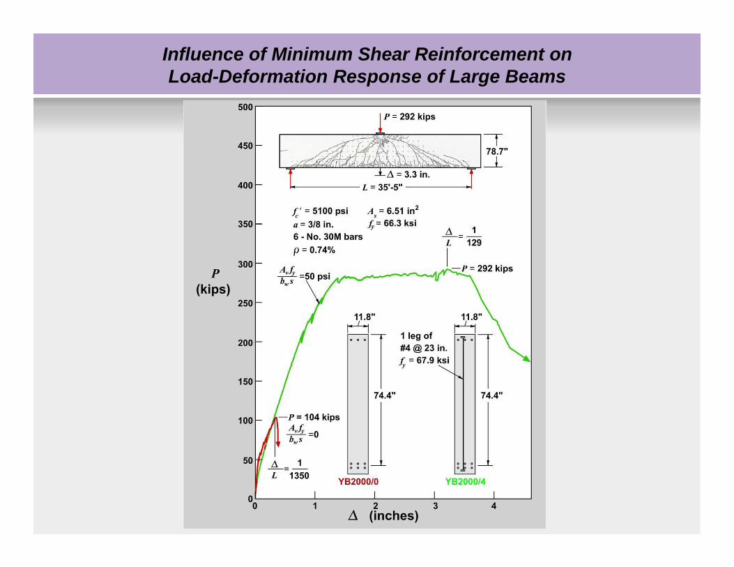
Influence of Minimum Shear Reinforcement on Load-Deformation Response of Large Beams
28
1. Introduction
2.Why fracture mechanics in concrete?
3.Fracture mechanics for concrete
4.Computational Models for fracture
Fracture Mechanics for Structural Concrete
29
Linear elastic fracture mechanics allows the stress to approach infinity at a crack tip.
However, infinite stress cannot develop in real materials.
A certain range of inelastic zone must exist around crack tip.
In metal, this zone is a yielding zone.
At the crack tip,
Fracture mechanics for concrete
30
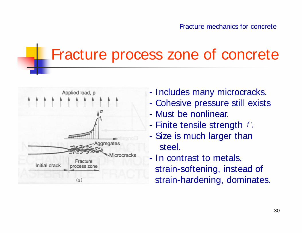
- Includes many microcracks.- Cohesive pressure still exists- Must be nonlinear.- Finite tensile strength - Size is much larger than
steel.- In contrast to metals, strain-softening, instead ofstrain-hardening, dominates.
Fracture process zone of concrete
'tf
Fracture mechanics for concrete
31
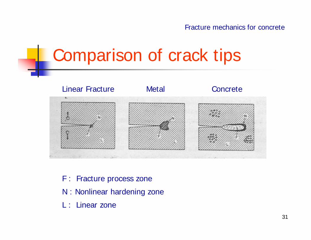
Comparison of crack tips
Fracture mechanics for concrete
Linear Fracture Metal Concrete
F : Fracture process zone
N : Nonlinear hardening zone
L : Linear zone
32
In ductile metal, fracture process zone, which shows strain-softening, is usually small.
In concrete, fracture process zone is large compared to metal.
Therefore, in concrete, crack tip is not defined clearly.
Comparison of crack tips (Cont’d)
Fracture mechanics for concrete
33
Fracture energy is the energy required to open unit area of crack surface.
Fracture energy is a material constant.
It is independent of structure size or geometry of structure.
Fracture energy
Fracture mechanics for concrete
34
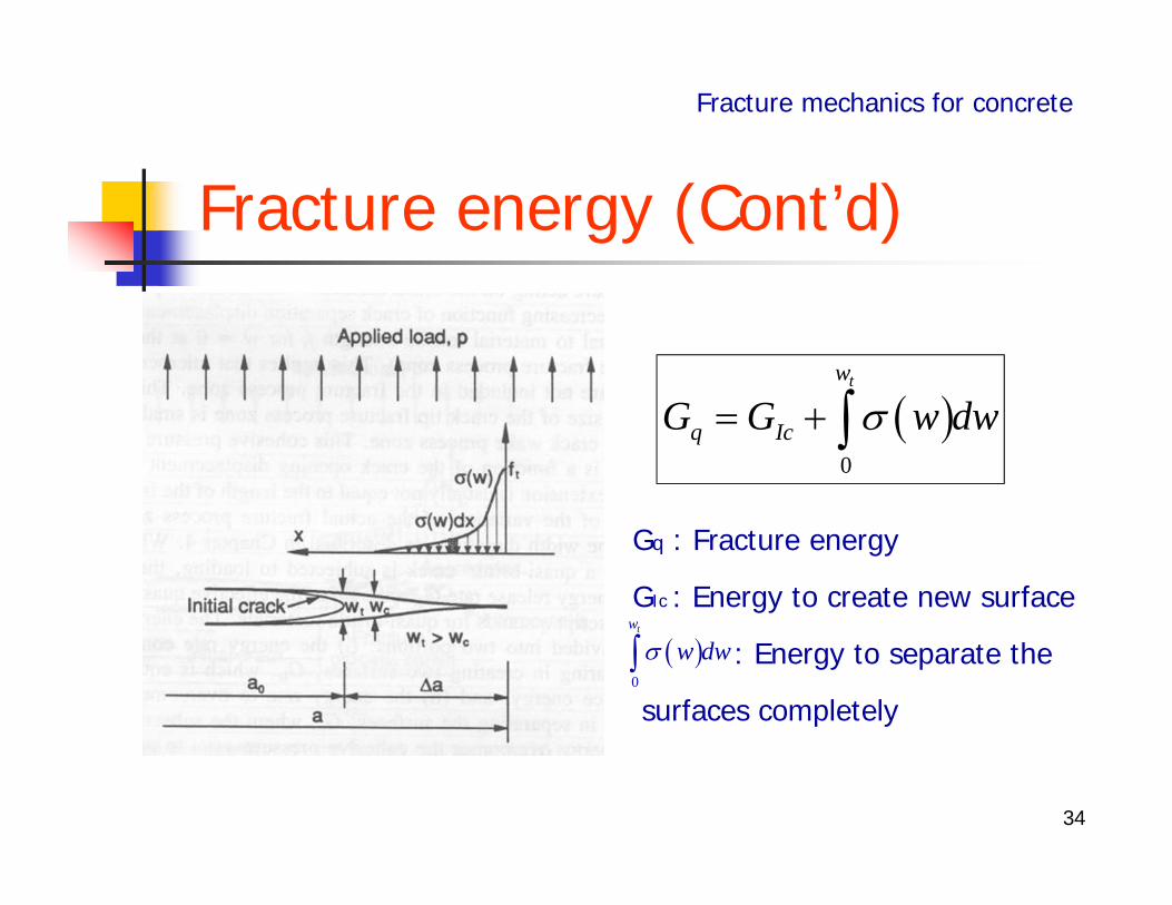
Gq : Fracture energy
GIc : Energy to create new surface
: Energy to separate the
surfaces completely
Fracture energy (Cont’d)
Fracture mechanics for concrete
0
tw
q IcG G w dw
0
tw
w dw
35
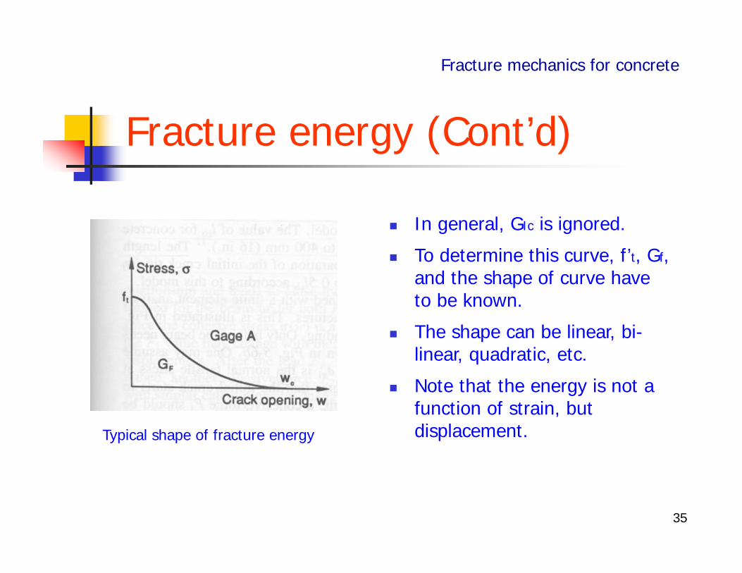
In general, GIc is ignored.
To determine this curve, f’t, Gf, and the shape of curve have to be known.
The shape can be linear, bi-linear, quadratic, etc.
Note that the energy is not a function of strain, but displacement.
Fracture energy (Cont’d)
Fracture mechanics for concrete
Typical shape of fracture energy
36
1. Introduction
2.Why fracture mechanics in concrete?
3.Fracture mechanics for concrete
4.Computational Models for fracture
Fracture Mechanics for Structural Concrete
37
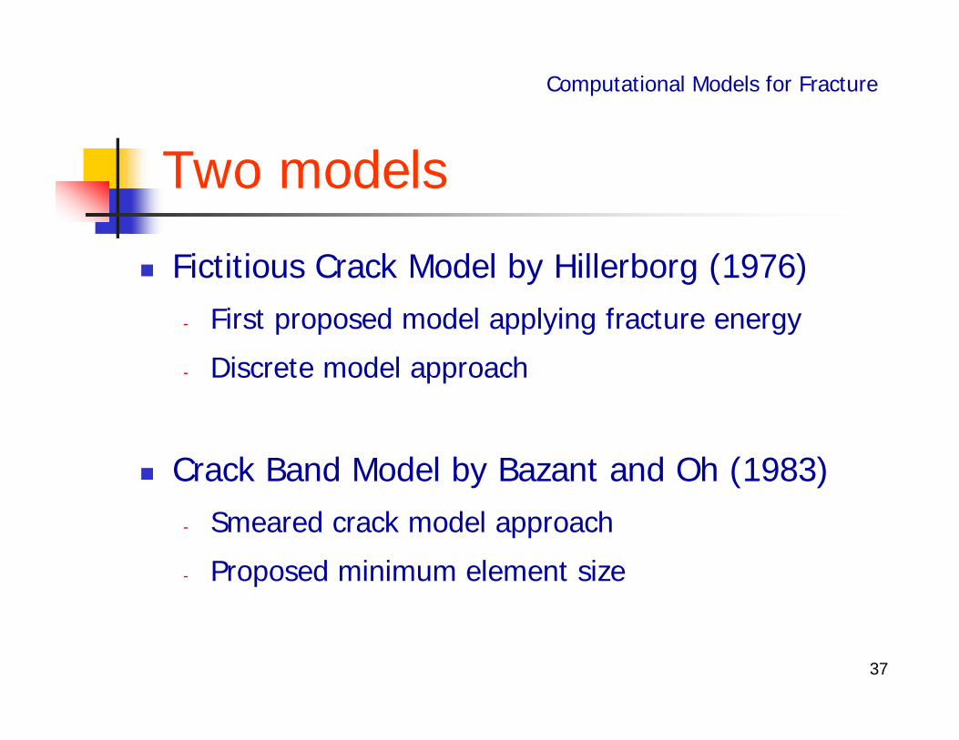
Fictitious Crack Model by Hillerborg (1976)- First proposed model applying fracture energy
- Discrete model approach
Crack Band Model by Bazant and Oh (1983)- Smeared crack model approach
- Proposed minimum element size
Two models
Computational Models for Fracture
38
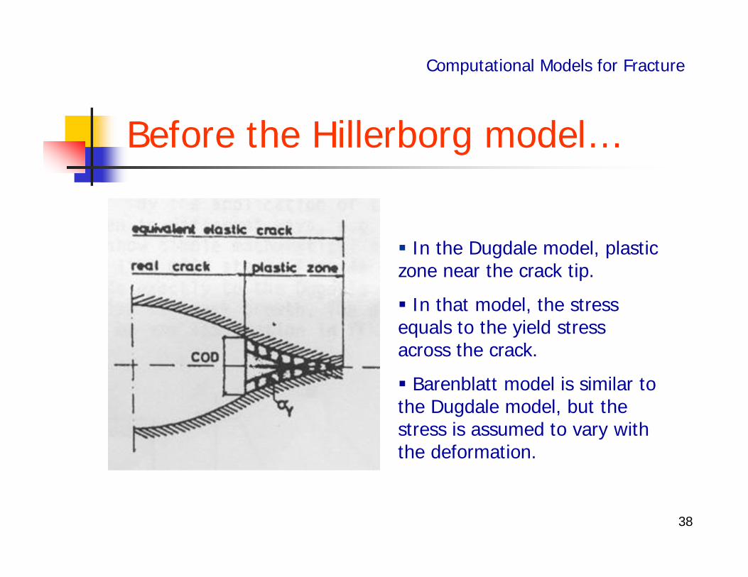
Before the Hillerborg model…
Computational Models for Fracture
In the Dugdale model, plastic zone near the crack tip.
In that model, the stress equals to the yield stress across the crack.
Barenblatt model is similar to the Dugdale model, but the stress is assumed to vary with the deformation.
39
Fictitious crack model -assumption
Computational Models for Fracture
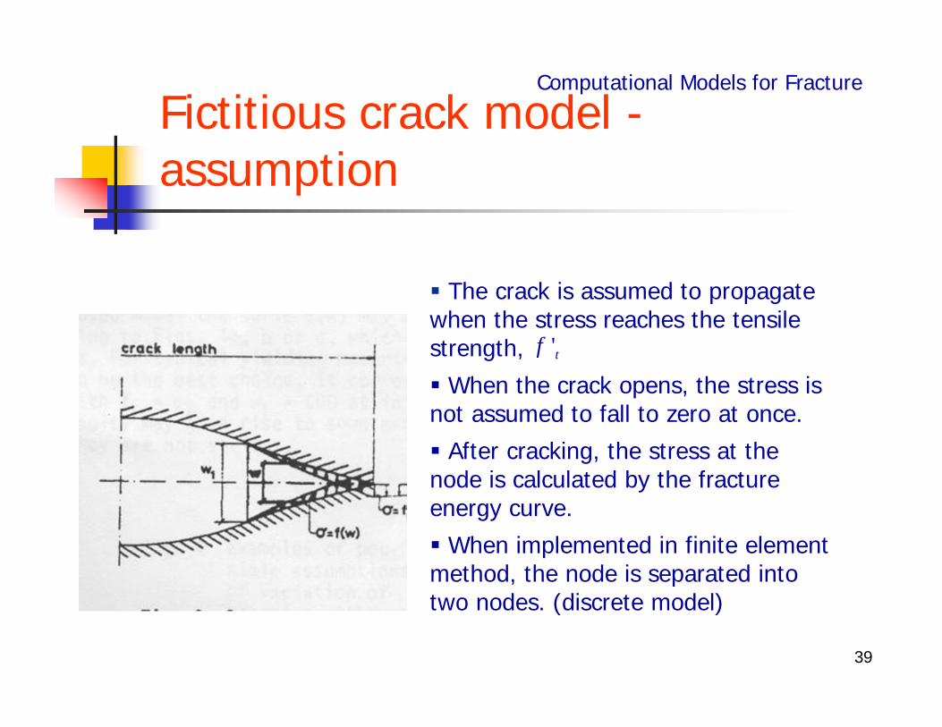
The crack is assumed to propagate when the stress reaches the tensile strength, When the crack opens, the stress is not assumed to fall to zero at once. After cracking, the stress at the node is calculated by the fracture energy curve. When implemented in finite element method, the node is separated into two nodes. (discrete model)
'tf
40
Fictitious crack model - Example
Computational Models for Fracture
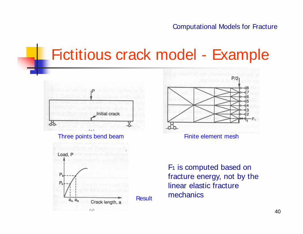
Three points bend beam Finite element mesh
Result
F1 is computed based on fracture energy, not by the linear elastic fracture mechanics
41
Characteristic length
Computational Models for Fracture
Hillerborg introduced the concept of characteristic length,
Characteristic length is material property also.
Characteristic length is index for the brittleness.
If it is large, the material is ductile, whereas if it is small, brittle.
2/ 'c c tl EG f
42
Fictitious crack mode -Shortcomings
Computational Models for Fracture
When the crack extends through a certain node, the node must be split into two nodes.
The optimized band should be calculated in each step.
If the direction of crack is not known in advance, identifying the direction in which the energy release rate is maximum should be carried out.
43
Fictitious crack mode –Shortcomings (cont’d)
Computational Models for Fracture
Even if the calculation is possible, the direction may not propagate through nodes. In that case, the calculation may be misleading.
44
Crack band model - Introduction
Computational Models for Fracture
In the theory of randomly inhomogeneous materials, equivalent continuum stresses and strains are defined over a certain representative volume. The volume size must be at least several times the maximum aggregate size. The distribution of stress or strain over distance less than several aggregate sizes has no physical meaning.
45
Crack band model – Introduction (Cont’d)
Computational Models for Fracture
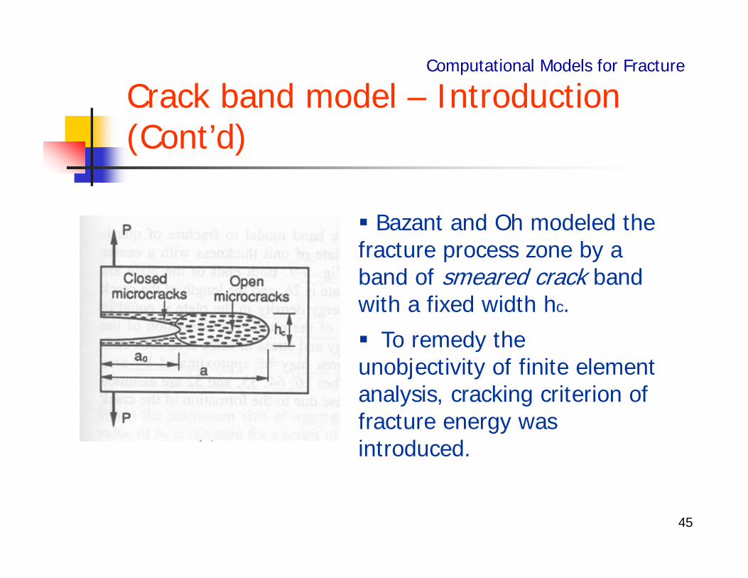
Bazant and Oh modeled the fracture process zone by a band of smeared crack band with a fixed width hc. To remedy the unobjectivity of finite element analysis, cracking criterion of fracture energy was introduced.
46
Crack width of crack band model
Computational Models for Fracture
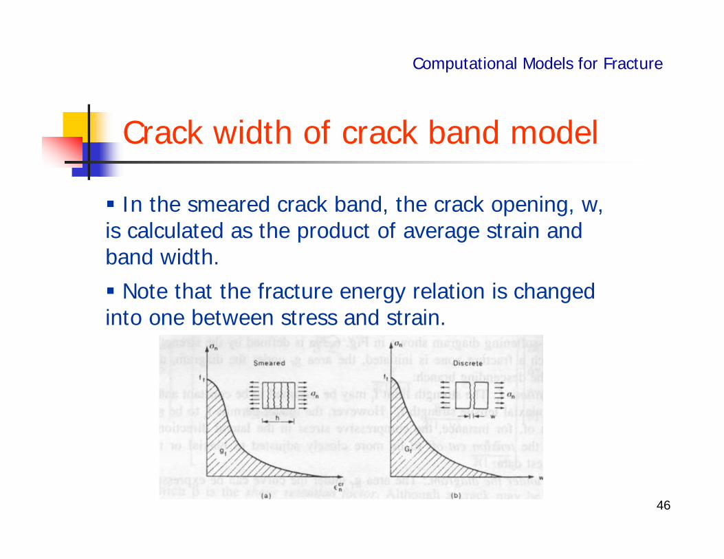
In the smeared crack band, the crack opening, w, is calculated as the product of average strain and band width. Note that the fracture energy relation is changed into one between stress and strain.
47
Crack band width
Computational Models for Fracture
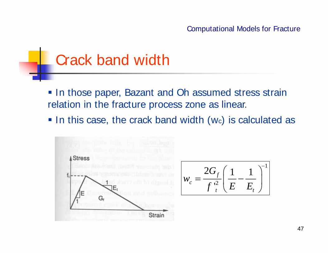
In those paper, Bazant and Oh assumed stress strain relation in the fracture process zone as linear. In this case, the crack band width (wc) is calculated as
1
2
2 1 1'
fc
t t
Gw
f E E
48
Characteristics of cracked element
Computational Models for Fracture
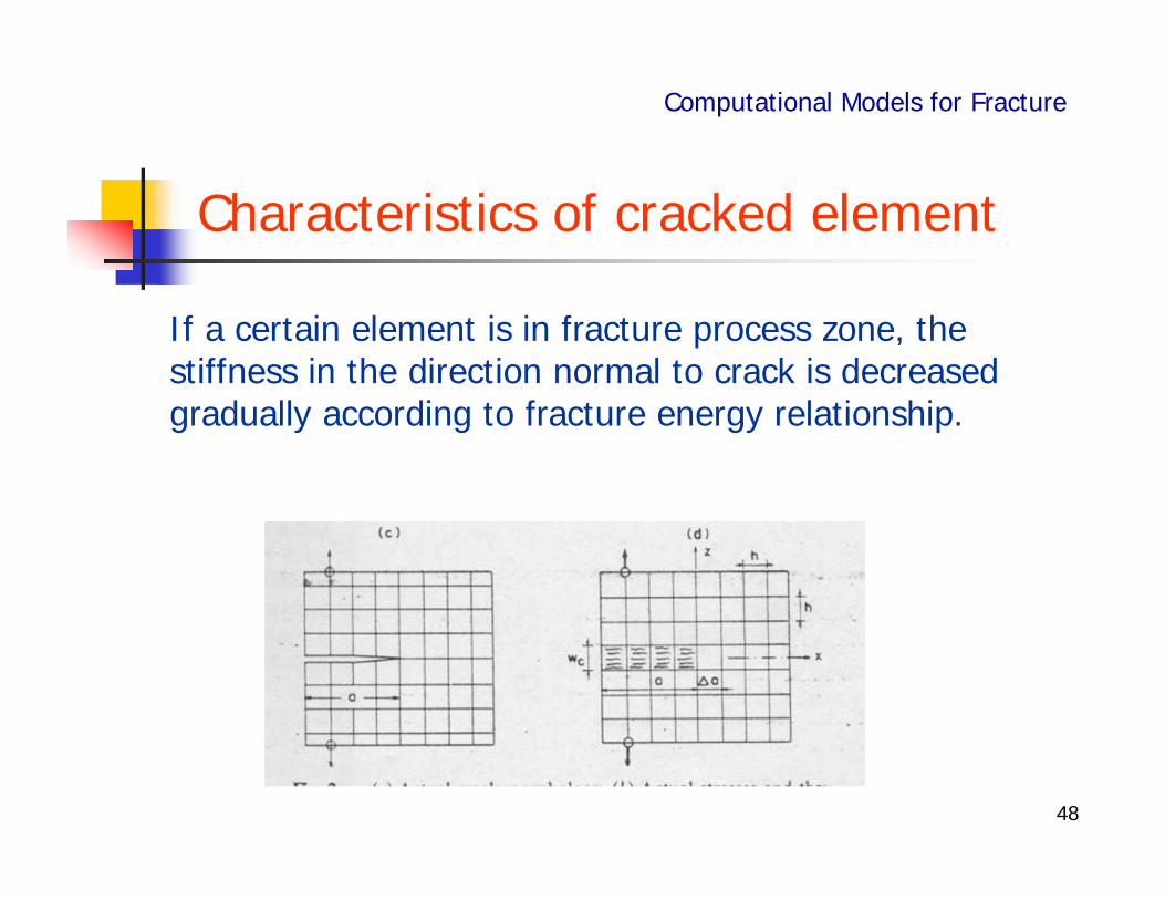
If a certain element is in fracture process zone, the stiffness in the direction normal to crack is decreased gradually according to fracture energy relationship.
49
Characteristics of cracked element (Cont’d)
1 01 1 0
1
x x
y y
z z f
E
Computational Models for Fracture
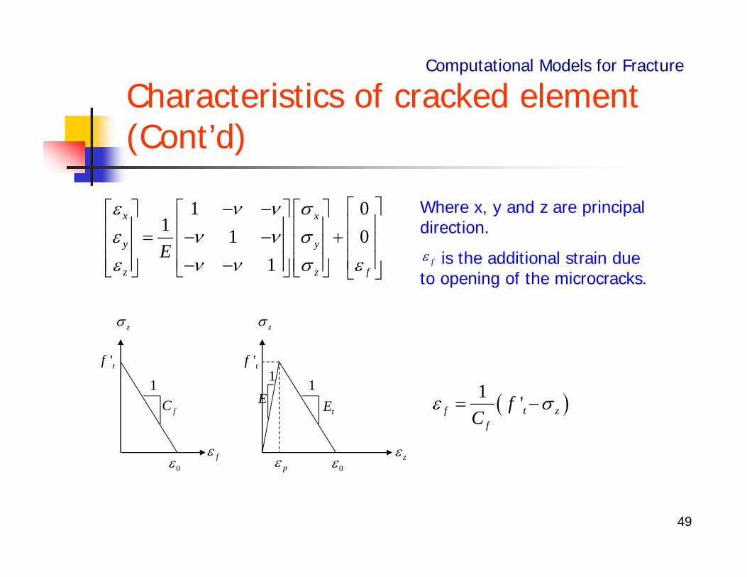
Where x, y and z are principal direction.
is the additional strain due to opening of the microcracks.
f
1 'f t zf
fC
z z
f z
'tf 'tf
0 0p
fC1
E1
tE1
50
Characteristics of cracked element (Cont’d)
0
1 01 1 0
x x
y y
z t z
EE E
Computational Models for Fracture
0
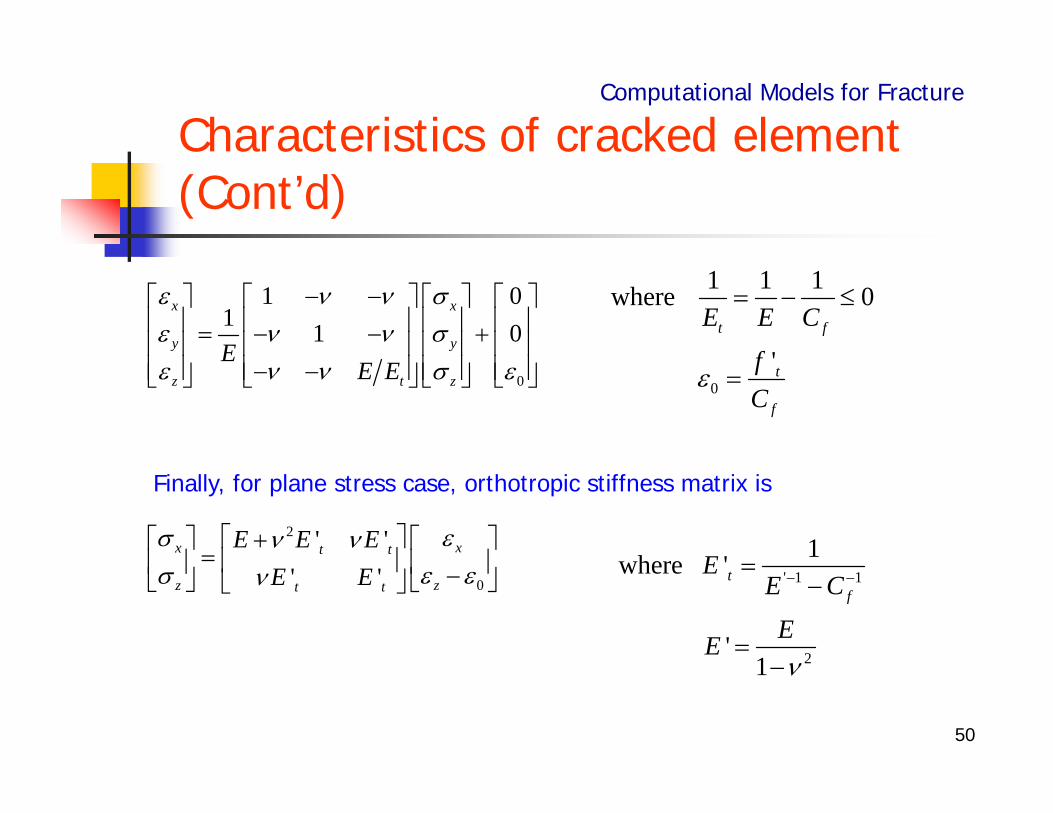
1 1 1where 0
'
t f
t
f
E E C
fC
Finally, for plane stress case, orthotropic stiffness matrix is
2
0
' '' '
xx t t
zz t t
E E EE E
' 1 1
2
1where '
'1
tf
EE C
EE
51
Element size of crack band model
Computational Models for Fracture
In finite element analysis, the crack band width is the element size of fracture process path. Since the size of fracture process zone is wc, the smaller element than wc makes no sense. However, larger element than wc can be used with proper correction. The crack width will be the product of crack band width and element strain.