Embed Size (px)
Citation preview
17 International Journal of Transportation Engineering, Vol.5/ No.1/ Summer 2017
Experimental Analysis of Fracture and Damage Mechanics
of Pre-Stressed Concrete Sleepers B70: Part B- Analysis
Seyed .Mohammad Farnam1, Fereydoon Rezaie2
Received: 11. 07. 2016 Accepted: 31. 10. 2016
Abstract Initial cracks occur in high strength concrete sleepers for various reasons, such as shrinkage and wrong
curing and long lifetime of over 50 years of sleepers. These cracks may lead to complete failure of the
structure. In order to more accurately design the sleepers, fracture mechanics (not strength of materials)
should be incorporated. In order to achieve this purpose, it is important to forecast crack growth and
residual strength reduction rate. In this study, based on the principles of nonlinear fracture mechanics
(NLFM) in concrete material, fracture behavior of pre-stressed concrete sleepers was investigated.
Sleepers with the lengths of initiation crack of 5 mm with 10 mm step increasing to 45 mm were tested.
Five specimens in each group were loaded under three-point bending test, in order to calculate IcK , crack
growth, and load-displacement diagram. The results showed that by increasing the crack-to-depth ratio,
initial toughness, crack stability, and crack unstable toughness, the crack instability expansion begins. By
increasing the crack-to-depth ratio, both initial and unstable toughness values increased linearly versus
LEFM theory. Damage begins with an initial crack like in flexural damage and then continues with
bifurcation of the crack. The influence of shear damage in sleeper's crack growing leads it to the ultimate
damage.
Keywords: Fracture mechanics, damage mechanics, pre-stressed concrete sleeper b70, stress
intensity factor, crack-to-depth ratios.
Corresponding author E-mail: [email protected] 1 Ph.D Candidate, Department of Civil Engineering, Bu-Ali Sina University, Hamedan, Iran 2 Associate Professor, Department of Civil Engineering, Bu-Ali Sina University, Hamedan, Iran
1. Introduction
Railway transportation is among the most
popular modes of transportation in the world
Experimental Analysis of Fracture and Damage Mechanics of Pre-Stressed Concrete …
International Journal of Transportation Engineering, 18 Vol.5/ No.1/ Summer 2017
and therefore maintaining its safety seems to
be of great importance. To achieve this goal,
various issues, including possible modes of
different components of the railway lines
should be analyzed. Sleepers are one of the
main railroad components, receiving the
force from the wheels and conveying it to the
rails. The force is then transferred to the
ballast layer, while a constant spacing
between the lines is maintained [Zhao, Chan
and Burrow, 2007]. Sleepers are constructed
from different materials, such as timber,
steel, and concrete [Thai and Kim, 2014].
Timber sleepers were used in the past, but
nowadays, their usage has been limited due
to the high prices and scarcity of wood. On
the other hand, concrete elements could not
be eaten by insects and fungi, so they have a
good resistance to environmental conditions.
Therefore, the use of concrete sleepers has
increased rapidly. Moreover, concrete
sleepers are very low in price as compared to
the timber sleepers. However, with the
development of railway lines and abundance
of heavy wagons and high-speed trains, these
elements have proven to be inefficient.
Therefore, sleepers with high-strength
concrete and rebar are used to achieve high
resistance. Since mono-block B70 pre-
stressed concrete sleepers have high strength,
more durable, and are also lighter than other
sleepers, their usage is more common in I. R.
Iran railway system.
Remennikov and Kaewuruen investigated
the static behavior of pre-stressed concrete
sleepers with an experimental method in
view of non-linear properties of the materials
[Remennikov and Kaewuruen, 2006]. They
also compared the numerical and
experimental response of the pre-stressed
concrete sleepers under static and impact of
loads with low velocity [Remennikov and
Kaewuruen, 2007; Kaewuruen and
Remennikov, 2007]. Rezaie and co- authors
studied longitudinal crack propagation in
pre-stressed concrete sleepers. In their
experimental and numerical studies, the
effects of extra pressure in rawlplug
positions were modeled by applying
cylindrical pressure inside the holes [Rezaie,
Shiri and Farnam, 2012]. Fracture and
damage mechanics of pre-stressed concrete
sleepers B70 were analyzed experimentally.
González-Nicieza and co-authors
investigated the failure analysis of a railway
track used for transporting heavy haul
industrial freight [González-Nicieza et al,
2008]. Three dimensional finite element
methods and a series of experimental
programs are used to examine the failure
mechanism of concrete railway sleepers by
Goangseup Zi and colleagues [Goangseup Zi
et al. 2012]. Also, in 2014, fatigue and
failure of Pre-stressed concrete sleepers (or
railroad ties) were investigated using full-
scale experimental tests [Remennikov and
Kaewuruen, 2014].
From a fracture mechanics point of view,
concrete behavior is quasi-brittle. Therefore,
linear elastic fracture mechanics (LEFM)
theory can be probably used to describe
crack growth, fracture toughness, and other
fracture mechanics parameters of concrete.
The use of LEFM for concrete was
documented by Kaplan [Kaplan, 1961];
however, it has been shown by a number of
researchers, including Shah and Mac-Garry
[Shah and Mac-Garry, 1971] that it is not an
appropriate choice. In order to determine
fracture mechanics model of concrete, a
large number of experimental and numerical
studies have been carried out. Several
research works investigate the fracture
properties of concrete elements in different
conditions for specimens of different sizes.
[Vesely, Konecny and Lehner, 2015;
Eftekhari, Ardakani and Mohammadi, 2014;
Santosh and Ghosh, 2015]. Azad and co-
S.M. Farnam, F. Rezaie
19 International Journal of Transportation Engineering, Vol.5/ No.1/ Summer 2017
authors investigated an experimental test
which was performed on a series of simply
supported concrete beams in order to
determine the fracture energy of the
composite beam and predict the flexural
strength by applying the fracture mechanics
concept [Azad, Mirza and Chan, 2007]. Ruiz
et al. studied the fracture in lightly reinforced
concrete beams using a method which
showed that there is a direct relationship
between load capacities and rebar ratio in the
beam cross section [Ruiz, Elices and Planas,
1998]. Evaluation of the minimum
reinforcement in the bridged crack model of
concrete members has been examined
experimentally and theoretically by Ferro
and co-authors [Ferro, Carpinteri and
Ventura, 2007]. In 2011, Shaowei and
colleagues used an acoustic emission
practice to find the parameters of normal
concrete fracture properties [Shaowei, Jun
and Xiaoqing, 2011]. Zhao and co authors
investigated experimentally the uniaxial
tensile creep behavior of pre-cracked steel
fiber reinforced concrete. Cylindrical
specimens were pre-cracked at crack
opening displacement (COD) for damage
evolution [Zhao, Prisco, and Vandewalle,
2015]. In recent years, studies have been
conducted analyzing fracture mechanics of
reinforced concrete; however, very few of
these studies have addressed pre-stressed
concrete, especially, using experimental and
numerical methods [Rezaie, Shiri and
Farnam, 2012]. Therefore, in this paper, the
emphasis is placed on the experimental
analysis of fracture and damage mechanics
of pre-stressed concrete sleepers B70. The
main fracture parameters of a notched pre-
stressed concrete sleeper, such as the force-
displacement diagram, crack growth, and K𝐼c
are calculated with NLFM theory. This
research consists of two parts, Part A and B.
In Part A, the experimental test is explained.
Replica test and image analysis are discussed
to calculate crack parameters like: crack
length, CMOD etc. In Part B, the results of
experimental tests such as force-
displacement and KIc and their effects on
analysis and design of pre-stressed concrete
sleepers are discussed.
2. Test Overview
2.1 Test Specimen
In this paper, center negative three-pointed
bending is applied to notched pre-stressed
concrete sleepers B70. In the majority of
railway codes, 3-point-bending is used for
the test. In fact, behaviors like a beam of pre-
stressed concrete sleepers are tested in 3-
point-bending. This method is also used for
other structures [Malvar and Warren, 1987;
Karihaloo and Nallathambi, 1989]. Loading
conditions are based on negative center load
test in “AREMA Chapter 30”, “Australian
Standard, AS 1085-14”. In Figure 1, the
actual geometrical sizes of pre-stressed
concrete sleepers are shown. Characteristic
of the mix design are shown in Table 1 for 1
m3 concrete. MaxD is the maximum size of
aggregate in the mix design.
Five different initial crack lengths, namely 5,
15, 25, 35, and 45 mm are created according
to the previously shown crack height and
after the cutting shown in Figure 2a and b,
respectively. Five specimens are made in
each group. Specimens' initial crack widths
are created as 8 mm with a portal crane with
a negligible thickness relative to that of the
specimen width.
Longitudinal rebar used for making the pre-
stressed concrete sleepers B70 is ST-160
with 7 mm diameter. The mechanical
characteristics of steel rebar are shown in
Table 2.
Experimental Analysis of Fracture and Damage Mechanics of Pre-Stressed Concrete …
International Journal of Transportation Engineering, 20 Vol.5/ No.1/ Summer 2017
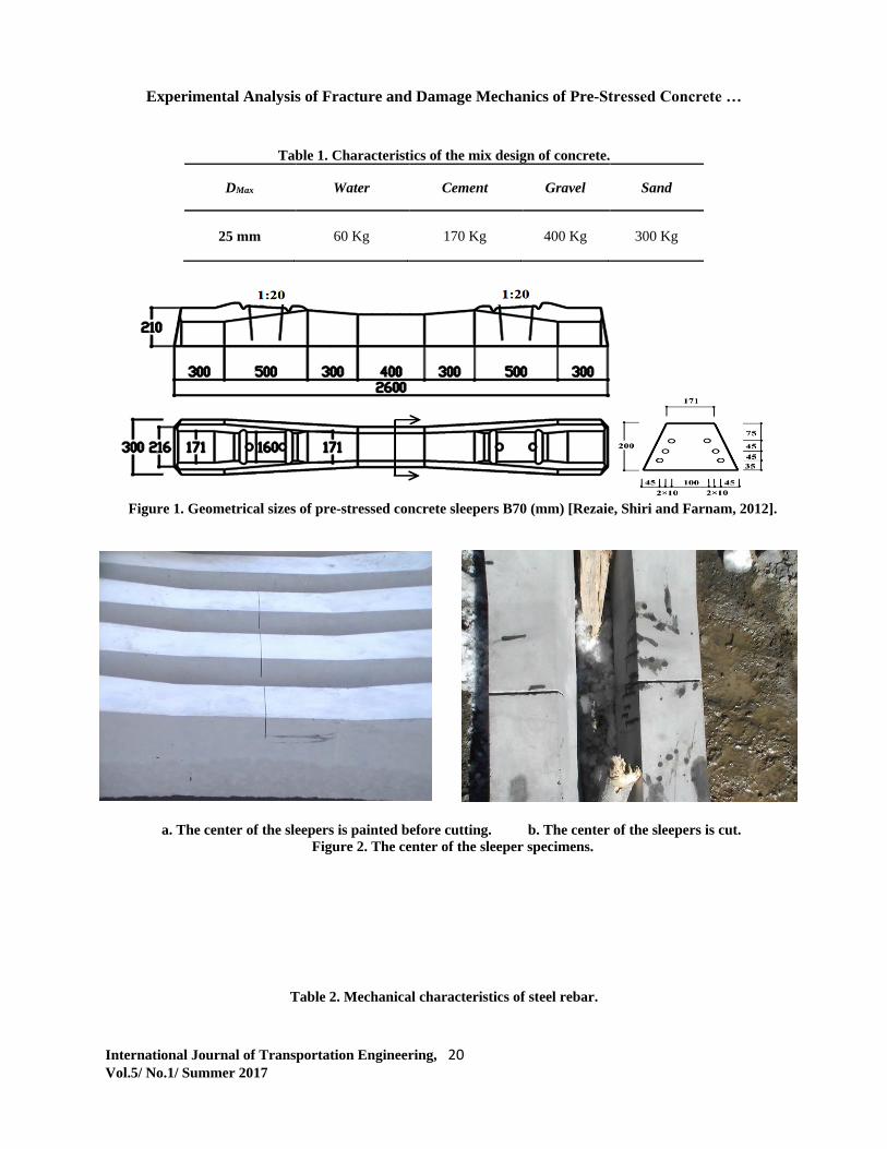
Table 1. Characteristics of the mix design of concrete.
MaxD Water Cement Gravel Sand
25 mm 60 Kg 170 Kg 400 Kg 300 Kg
Figure 1. Geometrical sizes of pre-stressed concrete sleepers B70 (mm) [Rezaie, Shiri and Farnam, 2012].
a. The center of the sleepers is painted before cutting. b. The center of the sleepers is cut.
Figure 2. The center of the sleeper specimens.
Table 2. Mechanical characteristics of steel rebar.
S.M. Farnam, F. Rezaie
21 International Journal of Transportation Engineering, Vol.5/ No.1/ Summer 2017
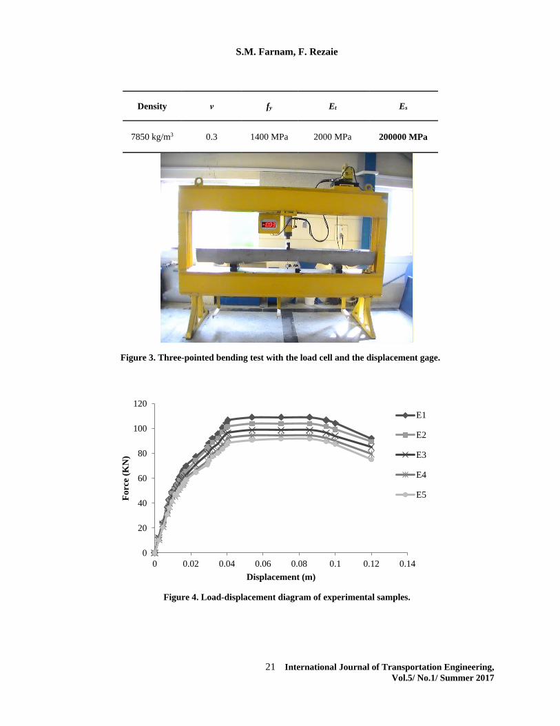
Es Et fy ν Density
200000 MPa 2000 MPa 1400 MPa 0.3 7850 kg/m3
Figure 3. Three-pointed bending test with the load cell and the displacement gage.
Figure 4. Load-displacement diagram of experimental samples.
0
20
40
60
80
100
120
0 0.02 0.04 0.06 0.08 0.1 0.12 0.14
Fo
rce
(KN
)
Displacement (m)
E1
E2
E3
E4
E5
Experimental Analysis of Fracture and Damage Mechanics of Pre-Stressed Concrete …
International Journal of Transportation Engineering, 22 Vol.5/ No.1/ Summer 2017
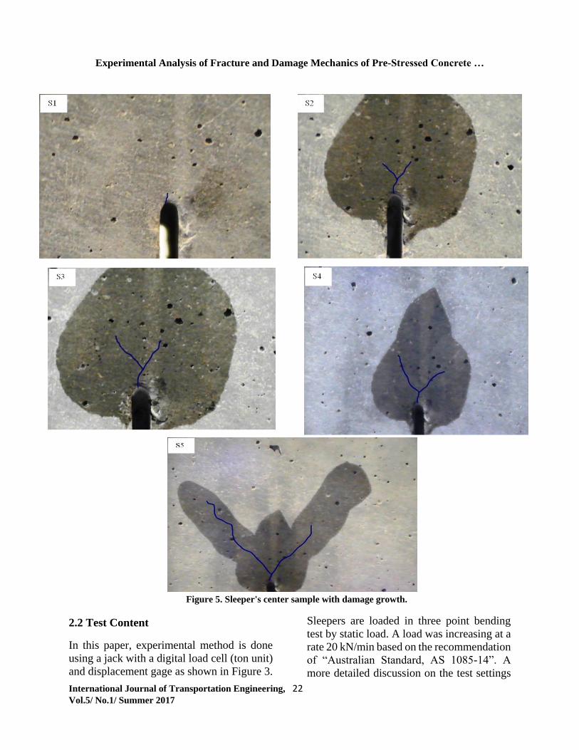
Figure 5. Sleeper's center sample with damage growth.
2.2 Test Content
In this paper, experimental method is done
using a jack with a digital load cell (ton unit)
and displacement gage as shown in Figure 3.
Sleepers are loaded in three point bending
test by static load. A load was increasing at a
rate 20 kN/min based on the recommendation
of “Australian Standard, AS 1085-14”. A
more detailed discussion on the test settings
S3
S.M. Farnam, F. Rezaie
23 International Journal of Transportation Engineering, Vol.5/ No.1/ Summer 2017
and the characteristics of concrete and rebar
could be found in Part A of the paper. The
main collected data includes load-
displacement diagram of the sleeper's pre-
stressed concrete, damage growth, and critical
toughness ( IcK ). In order to analyze the
whole load development process and to test
load initiation for each specimen, image
processing is used.
3. Results
3.1 Load-Displacement Diagram
In this section, experimental load-
displacement diagrams are measured. In fact
by testing full scale samples of pre-stressed
concrete sleepers, the results of the load-
displacement diagram are determined on the
initiation of the crack in the samples, as
shown in Figure 3. The load cell is placed on
the top of the jack at the mid-span and the
displacement gage is located at the bottom of
the sleeper center.
In these tests, 25 sleeper samples with initial
cracks are analyzed using the 30-step
method. Load and displacement data are
recorded. The average load-displacement
diagram resulting from 5 experimental
samples is as shown in Figure 4 for 5 initial
cracks. E1, E2, E3, E4, and E5 correspond to
5, 15, 25, 35, and 45 mm initial cracks,
respectively.
As shown in Figure 5, central area of the
sleeper in which the damage has occurred is
shown in 5 steps for experimental sample.
The damage grows larger step by step until
the final damage. In the first step (s1), the
initial damage appears at the central of the
sleeper exactly on the initial crack. It grows
more outwards after the expansion of the
cracks in an orthogonal direction. At the
second step (s2), the crack bifurcates and
starts to grow horizontally in a symmetric
manner. By the third, fourth, and fifth steps
(s3, s4, s5), the crack continues to grow in
vertical direction and causes damage as it
passes through the elements.
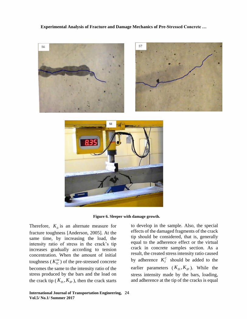
In Figure 6, at the sixth and seventh steps (s6,
s7), new cracks appear from the left and right
sides, respectively and they begin to
approach the center. The crack from the sides
is growing vertically around the central crack
which has reached the final damage level and
is heading to damage. So, it expands in a
variety of directions that lead to the final
damage level. At the final step (s8), the
sleeper has reached the final damage and
cannot bear more loads.
3.3 Stress Intensity of Critical Toughness
K𝐼c
3.3.1 Analytical Formula for Fracture NLFM
Parameters
During the manufacturing and preparation of
the pre-stressed concrete sleeper (such as
pulling and releasing the bars, curing of
concrete, etc.), the conditions are provided
for the creation of initial cracks in the sleeper.
Furthermore, the compressive stress in the
traction zone of pre-stressed concrete, which
is produced by the steel bars, postpones the
crack propagation speed and changes the
structural properties that cause an increase in
the damage capacity of the structure.
In fracture mechanics, the stress intensity
factor ( K ) is used to predict the stress
intensity (stress state) close to the tip of a
crack that is produced by a distant load or
residual stresses [Anderson, 2005]. The first
mode of critical stress intensity factor ( IcK)
is the most common mode used in fracture
mechanics design. If it is assumed that at
some critical combination of stress and
strain, the material fails locally, then the fracture must happen at critical stress intensity
IcK .
Experimental Analysis of Fracture and Damage Mechanics of Pre-Stressed Concrete …
International Journal of Transportation Engineering, 24 Vol.5/ No.1/ Summer 2017
Figure 6. Sleeper with damage growth.
Therefore, IcK is an alternate measure for
fracture toughness [Anderson, 2005]. At the
same time, by increasing the load, the
intensity ratio of stress in the crack’s tip
increases gradually according to tension
concentration. When the amount of initial
toughness ( ) of the pre-stressed concrete
becomes the same to the intensity ratio of the
stress produced by the bars and the load on
the crack tip ( ), then the crack starts
to develop in the sample. Also, the special
effects of the damaged fragments of the crack
tip should be considered, that is, generally
equal to the adherence effect or the virtual
crack in concrete samples section. As a
result, the created stress intensity ratio caused
by adherence should be added to the
earlier parameters ( ). While the
stress intensity made by the bars, loading,
and adherence at the tip of the cracks is equal
ini
ICK
,IS IPK K
C
IK
,IS IPK K
S.M. Farnam, F. Rezaie
25 International Journal of Transportation Engineering, Vol.5/ No.1/ Summer 2017
to the crack unstable toughness , the
crack instability expansion initiates and by
gradually disabling the concrete section
capacity, the load would be entirely tolerated
by the reinforcements. Thus, when the
damage in the reinforced concrete begins to
grow, the exact stress intensity ratio can be
obtained using Equations 1 and 2 by SL 352-
2006 “Test code for hydraulic concrete of
china”( Equations 1 and 2). Here, for the
stress intensity ratio, due to the loading on the
cracks when being unstable, it is assumed
that the bars are completely embedded in
concrete and no slipping happens between
them. The stress intensity factor created by
load can be obtained through Fracture Test of
Hydraulic Concrete in NLFM theory
(Equations 3-6). Where is a measure for
support conditions of the samples (according
to the conversion of ), is the length
among the supports, and is the length of the
whole sample. When the cracks are exposed
to the surface, the amount of the stress
intensity due to the bars can be calculated
using the following equations. (Equations 7
and 8) Where 0A is the area of bars cross
section, c is the distance between the rebar
in the center and the edge of the sample
section, 0
c
a , 0a
h , and ini
sF are the
responses of pre-stressing force when the
cracks appear in concrete. Furthermore, by
assuming bars being completely embedded in
concrete, the crack unstable toughness due to
the rebar on the crack's tip would be
calculated using Equations 9 and 10. in
concrete are unstable and Ca is the critical
crack length; also for the plastic zone, it
would have Where 1
C
c
a , 1
Ca
h , and
un
sF are the responses to the pre-stressing
force when the cracks (Equations 11 and 12):
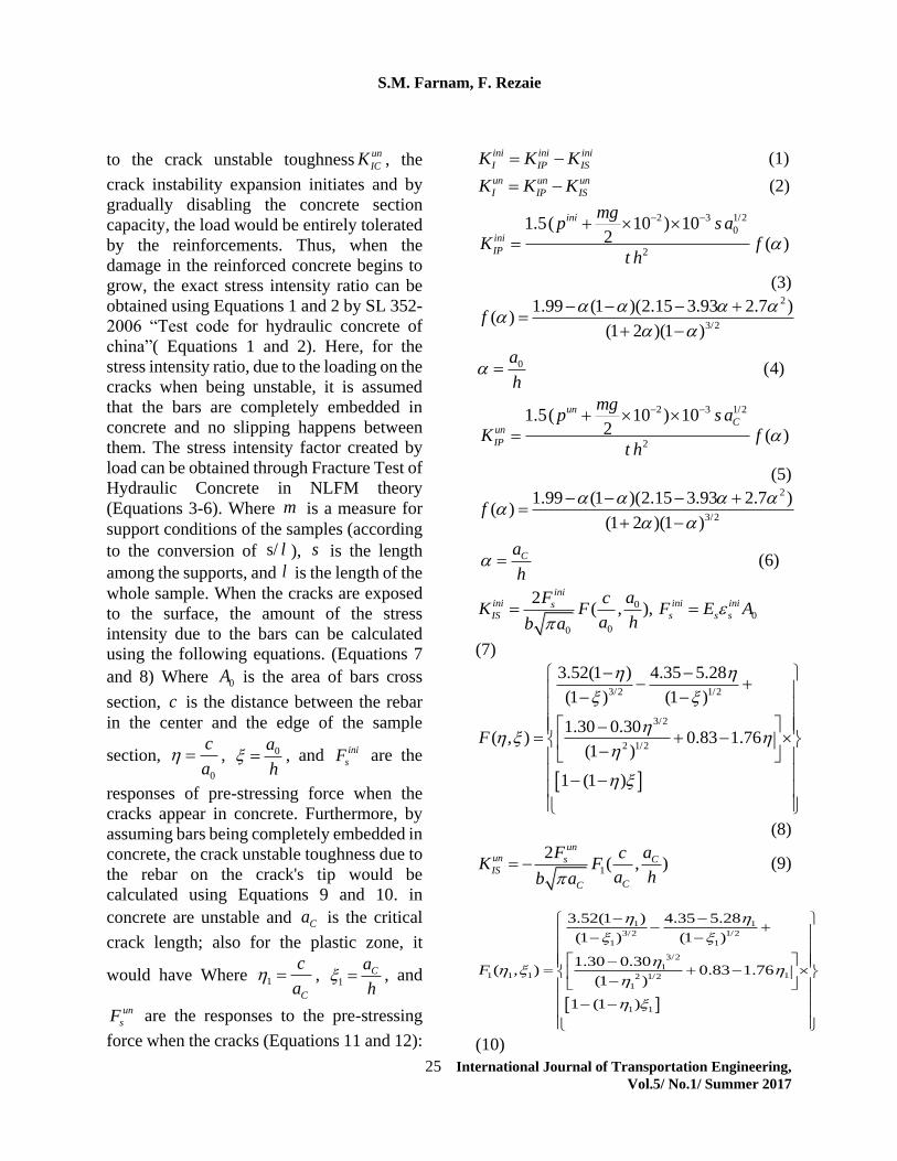
ini ini ini
I IP ISK K K (1)un un un
I IP ISK K K (2)
2 3 1/2
0
2
1.5( 10 ) 102 ( )
ini
ini
IP
mgp s a
K ft h
(3) 2
3/2
0
1.99 (1 )(2.15 3.93 2.7 )( )
(1 2 )(1 )
(4)
f
a
h
2 3 1/2
2
1.5( 10 ) 102 ( )
un
Cun
IP
mgp s a
K ft h
(5) 2
3/2
1.99 (1 )(2.15 3.93 2.7 )( )
(1 2 )(1 )
(6)C
f
a
h
00
00
2( , ),
iniini ini inisIS s s s
F acK F F E A
a hb a
(7)
3/2 1/2
3/2
2 1/2
3.52(1 ) 4.35 5.28
(1 ) (1 )
1.30 0.30( , ) 0.83 1.76
(1 )
1 (1 )
F
(8)
1
2( , )
unun s CIS
CC
F acK F
a hb a (9)
1 1
3/2 1/2
1 1
3/2
11 1 1 12 1/2
1
1 1
3.52(1 ) 4.35 5.28
(1 ) (1 )
1.30 0.30( , ) 0.83 1.76
(1 )
1 (1 )
F
(10)
un
ICK
m
s/ l s
l
Experimental Analysis of Fracture and Damage Mechanics of Pre-Stressed Concrete …
International Journal of Transportation Engineering, 26 Vol.5/ No.1/ Summer 2017
0 0
un un
s s yF A f A (11)
0 0
un un un
s s s sF A E A (12)
3.3.2 Stress Intensity Ratio Determination
To determine the stress intensity ratio, 5
samples of B70 pre-stressed concrete sleeper
are used. All the samples have the same
characteristics. The only difference between
them is the length of the initial crack. The
length of initial cracks in the samples ranges
from 5 to 45 mm with the growth step of 10
mm. According to the equations in the
previous section, the initial toughness ini
IK
and unstable toughness un
IK for the crack-to-
depth ratio is as shown in Figures 7 and 8.
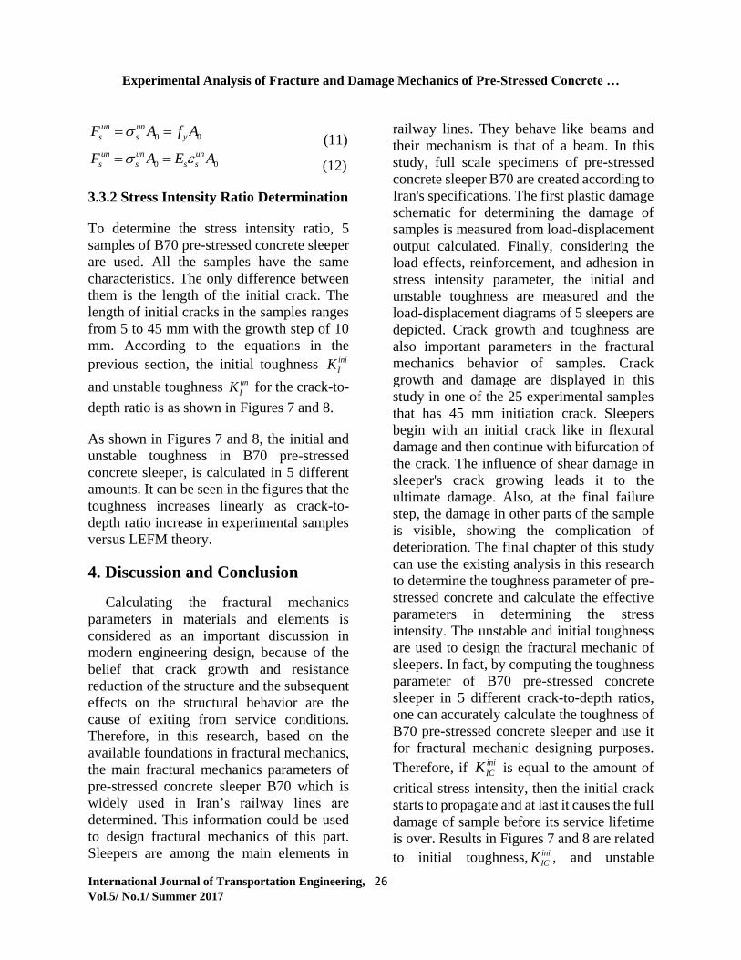
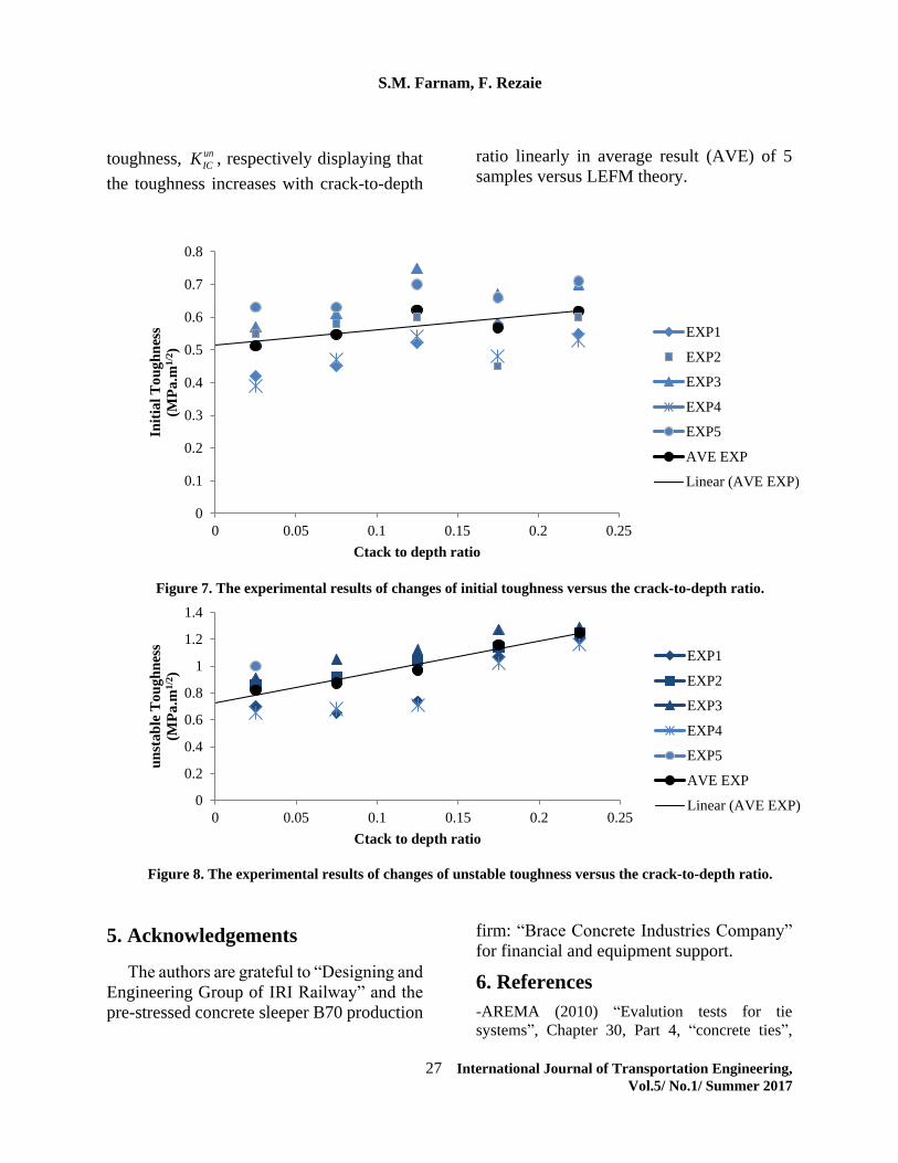
As shown in Figures 7 and 8, the initial and
unstable toughness in B70 pre-stressed
concrete sleeper, is calculated in 5 different
amounts. It can be seen in the figures that the
toughness increases linearly as crack-to-
depth ratio increase in experimental samples
versus LEFM theory.
4. Discussion and Conclusion
Calculating the fractural mechanics
parameters in materials and elements is
considered as an important discussion in
modern engineering design, because of the
belief that crack growth and resistance
reduction of the structure and the subsequent
effects on the structural behavior are the
cause of exiting from service conditions.
Therefore, in this research, based on the
available foundations in fractural mechanics,
the main fractural mechanics parameters of
pre-stressed concrete sleeper B70 which is
widely used in Iran’s railway lines are
determined. This information could be used
to design fractural mechanics of this part.
Sleepers are among the main elements in
railway lines. They behave like beams and
their mechanism is that of a beam. In this
study, full scale specimens of pre-stressed
concrete sleeper B70 are created according to
Iran's specifications. The first plastic damage
schematic for determining the damage of
samples is measured from load-displacement
output calculated. Finally, considering the
load effects, reinforcement, and adhesion in
stress intensity parameter, the initial and
unstable toughness are measured and the
load-displacement diagrams of 5 sleepers are
depicted. Crack growth and toughness are
also important parameters in the fractural
mechanics behavior of samples. Crack
growth and damage are displayed in this
study in one of the 25 experimental samples
that has 45 mm initiation crack. Sleepers
begin with an initial crack like in flexural
damage and then continue with bifurcation of
the crack. The influence of shear damage in
sleeper's crack growing leads it to the
ultimate damage. Also, at the final failure
step, the damage in other parts of the sample
is visible, showing the complication of
deterioration. The final chapter of this study
can use the existing analysis in this research
to determine the toughness parameter of pre-
stressed concrete and calculate the effective
parameters in determining the stress
intensity. The unstable and initial toughness
are used to design the fractural mechanic of
sleepers. In fact, by computing the toughness
parameter of B70 pre-stressed concrete
sleeper in 5 different crack-to-depth ratios,
one can accurately calculate the toughness of
B70 pre-stressed concrete sleeper and use it
for fractural mechanic designing purposes.
Therefore, if is equal to the amount of
critical stress intensity, then the initial crack
starts to propagate and at last it causes the full
damage of sample before its service lifetime
is over. Results in Figures 7 and 8 are related
to initial toughness, ini
ICK , and unstable
ini
ICK
S.M. Farnam, F. Rezaie
27 International Journal of Transportation Engineering, Vol.5/ No.1/ Summer 2017
toughness, un
ICK , respectively displaying that
the toughness increases with crack-to-depth
ratio linearly in average result (AVE) of 5
samples versus LEFM theory.
Figure 7. The experimental results of changes of initial toughness versus the crack-to-depth ratio.
Figure 8. The experimental results of changes of unstable toughness versus the crack-to-depth ratio.
5. Acknowledgements
The authors are grateful to “Designing and
Engineering Group of IRI Railway” and the
pre-stressed concrete sleeper B70 production
firm: “Brace Concrete Industries Company”
for financial and equipment support.
6. References
-AREMA (2010) “Evalution tests for tie
systems”, Chapter 30, Part 4, “concrete ties”,
0
0.1
0.2
0.3
0.4
0.5
0.6
0.7
0.8
0 0.05 0.1 0.15 0.2 0.25
Init
ial
To
ug
hn
ess
(MP
a.m
1/2
)
Ctack to depth ratio
EXP1
EXP2
EXP3
EXP4
EXP5
AVE EXP
Linear (AVE EXP)
0
0.2
0.4
0.6
0.8
1
1.2
1.4
0 0.05 0.1 0.15 0.2 0.25
un
sta
ble
To
ug
hn
ess
(MP
a.m
1/2
)
Ctack to depth ratio
EXP1
EXP2
EXP3
EXP4
EXP5
AVE EXP
Linear (AVE EXP)
Experimental Analysis of Fracture and Damage Mechanics of Pre-Stressed Concrete …
International Journal of Transportation Engineering, 28 Vol.5/ No.1/ Summer 2017
American Railway Engineering and Maintenance
of Way Association.
-AS-1085.14 (2012) Railway Track Material Part
14 : “Pre-stressed concrete sleepers”, Standard
Australia, 2012.
-Anderson, T. L. (2005) “Fracture mechanics:
Fundamentals and application”, 3rd. Ed., CRC
Press.
-Azad, A., Mirza, M. and Chan, P. (2007)
“Fracture energy of weakly reinforced concrete
beams”, Fatigue. and. Fract. of. Eng. Mater. and.
Struct. Vol. 12, pp.9–18.
-Eftekhari, M., Ardakani, S. H. and Mohammadi,
S. (2014) “An XFEM multiscale approach for
fracture analysis of carbon nanotube reinforced
concrete”, Theoretical and Applied. Fract. Mech.
Vol. 72, pp.64-75
-Ferro, G., Carpinteri, A. and Ventura, G. (2007)
“Minimum reinforcement in concrete structures
and material structural instability”, Int. J. of.
Fract., Vol. 146, pp.213–231.
-González-Niciezaa, C., Álvarez-Fernándeza, M.
I., Menéndez-Díazb, A., Álvarez-Vigilc, A. E.
and Ariznavarreta-Fernándeza, F. (2008)
“Failure analysis of concrete sleepers in heavy
haul railway tracks”, Eng. Fail. Anal. Vol. 15,
pp.90–117
-Kaewunruen, S. and Remennikov, A. M. (2007)
“Experimental and numerical studies of railway
pre-stressed concrete sleepers under static and
impact loads”, Asian Institute of Technology,
Civil Computing, Vol. 3, pp.25-28.
-Kaewunruen, S. and Remennikov, A. M. (2006)
“Nonlinear finite element modeling of railway
pre-stressed concrete sleeper”, Proceedings of
the 10th East Asia-Pacific Conference on
Structural Engineering and Construction
(EASEC-10), Bangkok, Thailand, August. Vol.
4, pp.323-328
-Kaplan, M. E. (1961) “Crack propagation and
the fracture concrete”, ACI. J. Vol. 58, pp.596-
610.
-Karihaloo, B. L. and Nallathambi, P. (1989)
“Fracture toughness of plain concrete from tree
bend specimens”, Mater. and. Struct. Vol. 22,
pp.185-193
-Malvar, L. J. and Warren, G. E. (1987) “Fracture
energy for three point bend tests on single edge
notched beams: Proposed evaluation”, Mater.
and. Struc. Vol. 20, pp.440-447.
-Remennikov, A. M. and Kaewunruen, S. (2014)
“Experimental load rating of aged railway
concrete sleepers”, Eng. Struct. Vol. 76, pp.147–
162.
-Remennikov, A. M. and Kaewunruen, S. (2007)
“Resistance of railway concrete sleepers to
impact loading”, Proceedings of the 7th.
International Conference on Shock and Impact
Loads on Structures, Beijing, China. pp.489-496.
-Rezaei, F., Shiri, M. R. and Farnam, S. M.
(2012) “Experimental and numerical studies of
longitudinal crack control for pre-stressed
concrete sleepers”, Eng. Fail. Anal. Vol. 26,
pp.21–30.
-Ruiz, G., Elices, M. and Planas, J. (1998)
“Experimental study of fracture of lightly
reinforced concrete beams”, Mater. and. Struct.
Vol. 31, pp.683–691.
-Santosh, M. and Ghosh, M. A. (2015) “Multi-
scale identification of concrete material
parameters”, Theoretical. and. Applied. Fract.
Mech. Vol. 75, pp.8-15.
Shah, S. P. and Mac-Garry, F. J. (1971) “Griffith
fracture criterion and concrete”, J. of. Eng. Mech.
Division. Vol. 97, pp.1663-1676.
-Shaowei, H. U., Jun, L. U. and Xiaoqing, Z.
(2011) “Study on characteristics of acoustic
emission property in the normal concrete fracture
test”, Adv. Mater. Res. Vol. 189-193, pp.1117–
1121.
SL (2006) 352-2006, Test code for hydraulic
concrete of china. “Water Conservancy and
Electric Power Press”, 2006.
S.M. Farnam, F. Rezaie
29 International Journal of Transportation Engineering, Vol.5/ No.1/ Summer 2017
-Thai, D. K. and Kim, S. E. (2014) “Analysis of
reinforced concrete walls under impact loading
using the finite element approach”, Eng. Fail.
Anal. Vol. 45, pp.252-277.
-Vesely, V., Konecny, P. and Lehner, P. (2015)
“Influence of crack propagation on electrical
resistivity and ultrasonic characteristics of
normal concrete assessed by sequential TPB
fracture test”, Theoretical. and. Applied. Fract.
Mech. Vol. 80, pp.2-13.
-Zhao, J., Chan, A. H. C. and Burrow, M. P. N.
(2007) “Reliability analysis and maintenance
decision for railway sleepers using track
condition information”, J. Oper. Res. Soc. Vol.
58, pp.1047–1055.