Embed Size (px)
Citation preview
04/10/2018
1
1
Master Mécanique-Matériaux-Structures-Procédés
Fracture Mechanics,
Damage and Fatigue
Chapter 1 - Introduction
Prof. Abderrahim Zeghloul Université de Lorraine
A. Zeghloul Fracture mechanics, damage and fatigue - Introduction 2
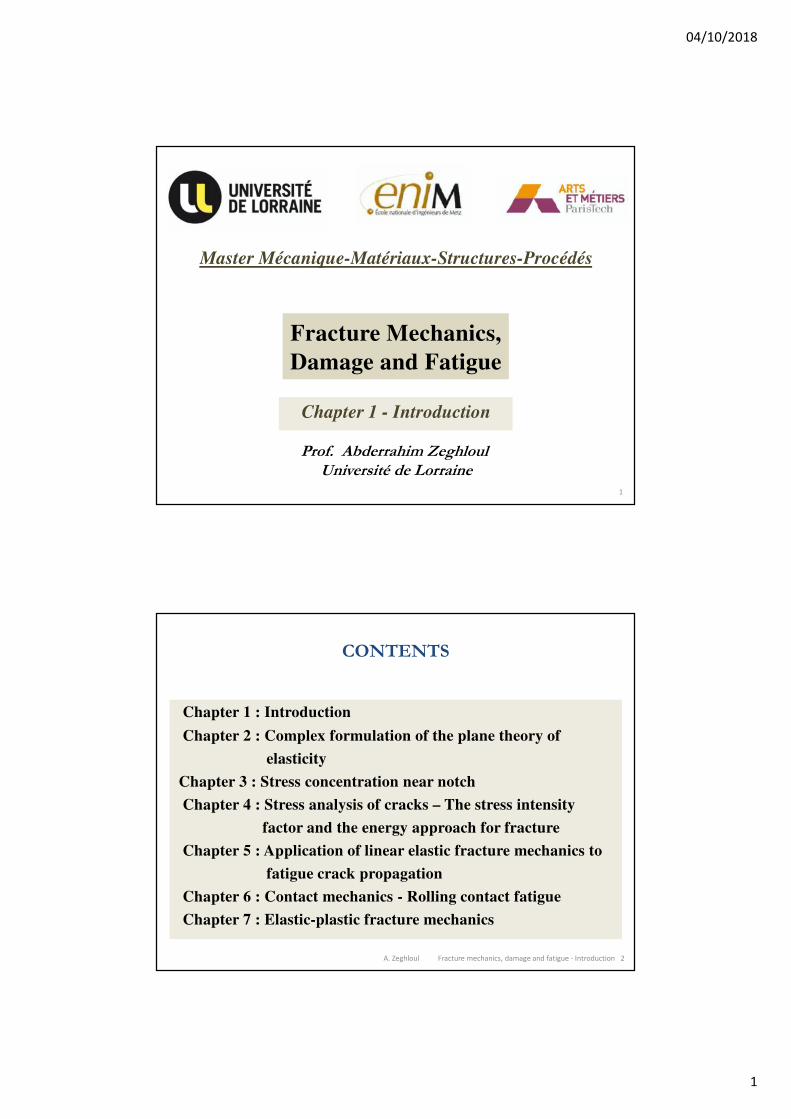
CONTENTS
Chapter 1 : Introduction
Chapter 2 : Complex formulation of the plane theory of
elasticity
Chapter 3 : Stress concentration near notch
Chapter 4 : Stress analysis of cracks – The stress intensity
factor and the energy approach for fracture
Chapter 5 : Application of linear elastic fracture mechanics to
fatigue crack propagation
Chapter 6 : Contact mechanics - Rolling contact fatigue
Chapter 7 : Elastic-plastic fracture mechanics
04/10/2018
2
A. Zeghloul Fracture mechanics, damage and fatigue - Introduction 3
Introduction
• Fracture phenomenon
- Fracture is a problem that society has faced for as long as there
have been man-made structures
- The problem may actually be worse today than in previous
centuries, because more can go wrong in our complex
technology society
- Economic studies estimated the cost of the fracture in
industrialized countries, about 4% of the gross national product
• Failures generally falls into one of the following categories
- Negligence during design or construction of the structure
- Application of new design or new material, which can produces
an unexpected (and undesirable) result (type 2 failures)
A. Zeghloul Fracture mechanics, damage and fatigue - Introduction 4
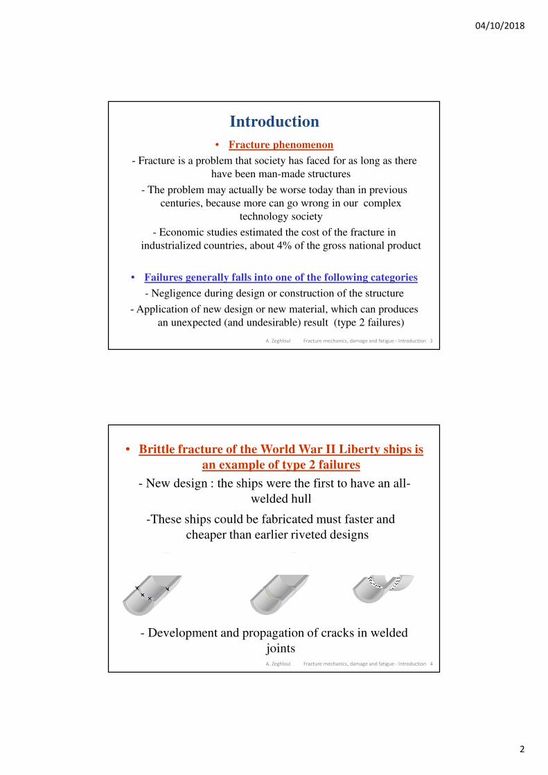
• Brittle fracture of the World War II Liberty ships is
an example of type 2 failures
- New design : the ships were the first to have an all-
welded hull
-These ships could be fabricated must faster and
cheaper than earlier riveted designs
×× ×
×
- Development and propagation of cracks in welded
joints
04/10/2018
3
A. Zeghloul Fracture mechanics, damage and fatigue - Introduction 5
A. Zeghloul Fracture mechanics, damage and fatigue - Introduction 6
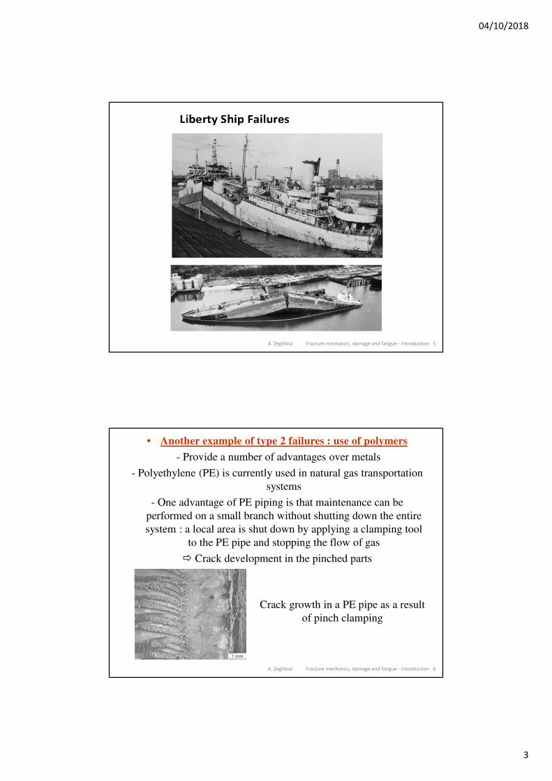
• Another example of type 2 failures : use of polymers
- Provide a number of advantages over metals
- Polyethylene (PE) is currently used in natural gas transportation
systems
- One advantage of PE piping is that maintenance can be
performed on a small branch without shutting down the entire
system : a local area is shut down by applying a clamping tool
to the PE pipe and stopping the flow of gas
Crack development in the pinched parts
Crack growth in a PE pipe as a result
of pinch clamping
04/10/2018
4
A. Zeghloul Fracture mechanics, damage and fatigue - Introduction 7
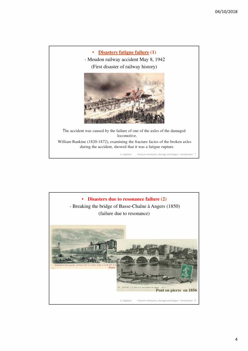
• Disasters fatigue failure (1)
- Meudon railway accident May 8, 1942
(First disaster of railway history)
The accident was caused by the failure of one of the axles of the damaged
locomotive.
William Rankine (1820-1872), examining the fracture facies of the broken axles
during the accident, showed that it was a fatigue rupture.
A. Zeghloul Fracture mechanics, damage and fatigue - Introduction 8
• Disasters due to resonance failure (2)
- Breaking the bridge of Basse-Chaîne à Angers (1850)
(failure due to resonance)
Pont en pierre en 1856
04/10/2018
5
A. Zeghloul Fracture mechanics, damage and fatigue - Introduction 9
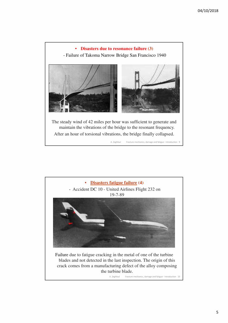
• Disasters due to resonance failure (3)
- Failure of Takoma Narrow Bridge San Francisco 1940
The steady wind of 42 miles per hour was sufficient to generate and
maintain the vibrations of the bridge to the resonant frequency.
After an hour of torsional vibrations, the bridge finally collapsed.
A. Zeghloul Fracture mechanics, damage and fatigue - Introduction 10
• Disasters fatigue failure (4)
- Accident DC 10 - United Airlines Flight 232 on
19-7-89
Failure due to fatigue cracking in the metal of one of the turbine
blades and not detected in the last inspection. The origin of this
crack comes from a manufacturing defect of the alloy composing
the turbine blade.
04/10/2018
6
A. Zeghloul Fracture mechanics, damage and fatigue - Introduction 11
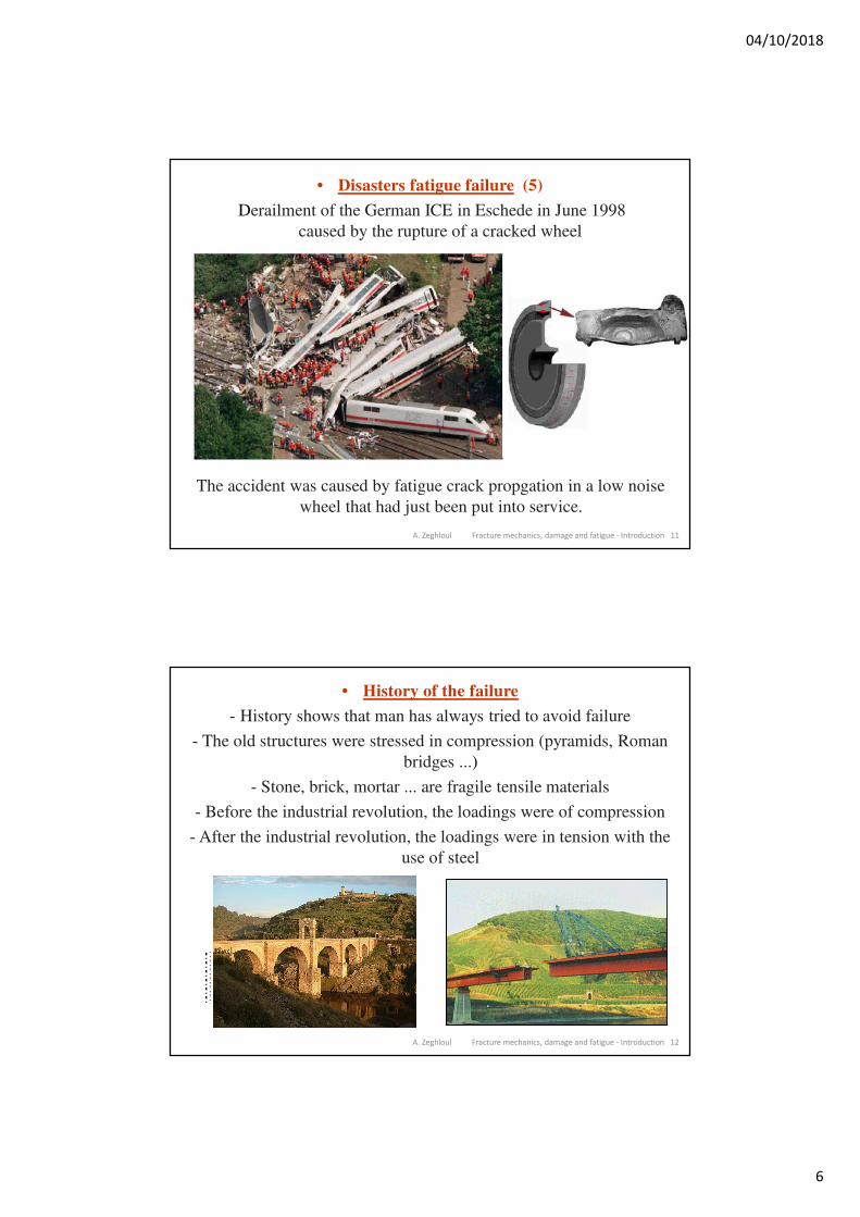
• Disasters fatigue failure (5)
Derailment of the German ICE in Eschede in June 1998
caused by the rupture of a cracked wheel
The accident was caused by fatigue crack propgation in a low noise
wheel that had just been put into service.
A. Zeghloul Fracture mechanics, damage and fatigue - Introduction 12
• History of the failure
- History shows that man has always tried to avoid failure
- The old structures were stressed in compression (pyramids, Roman
bridges ...)
- Stone, brick, mortar ... are fragile tensile materials
- Before the industrial revolution, the loadings were of compression
- After the industrial revolution, the loadings were in tension with the
use of steel
04/10/2018
7
A. Zeghloul Fracture mechanics, damage and fatigue - Introduction 13
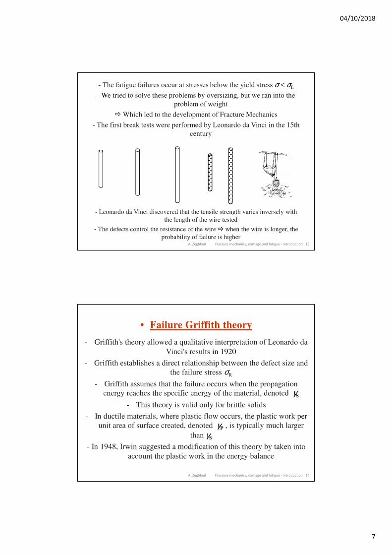
- The fatigue failures occur at stresses below the yield stress σ < σE
- We tried to solve these problems by oversizing, but we ran into the
problem of weight
Which led to the development of Fracture Mechanics
- The first break tests were performed by Leonardo da Vinci in the 15th
century
- Leonardo da Vinci discovered that the tensile strength varies inversely with
the length of the wire tested
- The defects control the resistance of the wire when the wire is longer, the
probability of failure is higher
A. Zeghloul Fracture mechanics, damage and fatigue - Introduction 14
• Failure Griffith theory
- Griffith's theory allowed a qualitative interpretation of Leonardo da
Vinci's results in 1920
- Griffith establishes a direct relationship between the defect size and
the failure stress σR
- Griffith assumes that the failure occurs when the propagation
energy reaches the specific energy of the material, denoted γS
- This theory is valid only for brittle solids
- In ductile materials, where plastic flow occurs, the plastic work per
unit area of surface created, denoted γP , is typically much larger
than γS
- In 1948, Irwin suggested a modification of this theory by taken into
account the plastic work in the energy balance
04/10/2018
8
A. Zeghloul Fracture mechanics, damage and fatigue - Introduction 15
• Failure Griffith theory
- In 1956, Irwin developed the concept of energy release rate,
denoted G
- In 1957, Irwin developed the concept of Stress Intensity Factor K
(based on the work of Westergaard and Mushkhélishvili) to describe
the fields of stress and strain at the tip of a crack
- The SIF K and the energy release rate G are two concepts of linear
elastic fracture mechanics interlinked ; a simple relationship exists
between these two parameters
- These two concepts have since been widely used to describe the
propagation of cracks
- The endurance curves have been supplemented by the crack
propagation curves
A. Zeghloul Fracture mechanics, damage and fatigue - Introduction 16
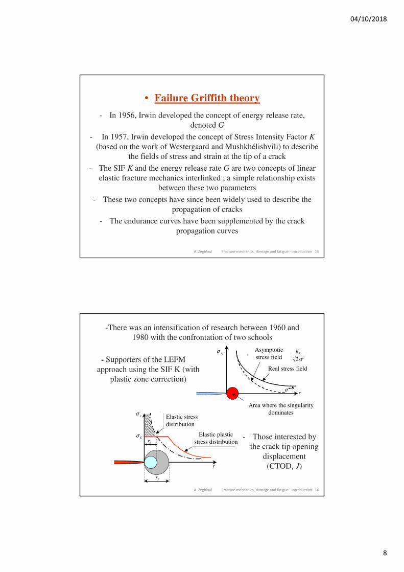
-There was an intensification of research between 1960 and
1980 with the confrontation of two schools
- Supporters of the LEFM
approach using the SIF K (with
plastic zone correction)
- Those interested by
the crack tip opening
displacement
(CTOD, J)
rE
rP
σ y
σ E
r
Répartition
élastique
Répartition
élasto plastique
Elastic stress
distribution
Elastic plastic
stress distribution
Champ asymptotique
Champ réel
σ yy K
r
I
2π
rσ ∞
Zone où la singularité domine
Asymptotic
stress field
Real stress field
Area where the singularity
dominates
04/10/2018
9
A. Zeghloul Fracture mechanics, damage and fatigue - Introduction 17
- Since the 1980s, research has focused on :
- viscoplastic behavior (high temperature ductile
materials, creep, fatigue-creep)
- viscoelastic behavior (polymeric materials)
- the behavior of composites (delamination, impact
effects ...)
- New, more recent approaches attempt to link the local
microscopic behavior at global macroscopic
behavior (micro-macro models)
A. Zeghloul Fracture mechanics, damage and fatigue - Introduction 18
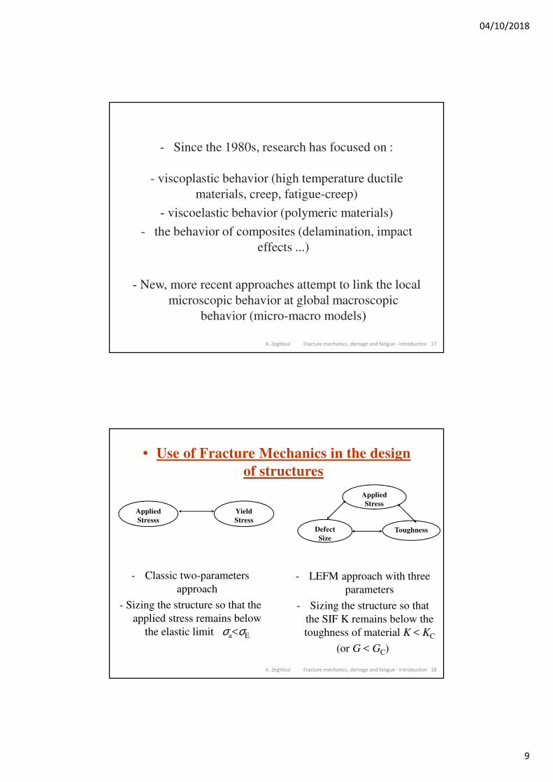
• Use of Fracture Mechanics in the design
of structures
Applied
Stresss
Yield
Stress
Defect
SizeToughness
Applied
Stress
- LEFM approach with three
parameters
- Sizing the structure so that
the SIF K remains below the
toughness of material K < KC
(or G < GC)
- Classic two-parameters
approach
- Sizing the structure so that the
applied stress remains below
the elastic limit σa<σE
04/10/2018
10
A. Zeghloul Fracture mechanics, damage and fatigue - Introduction 19
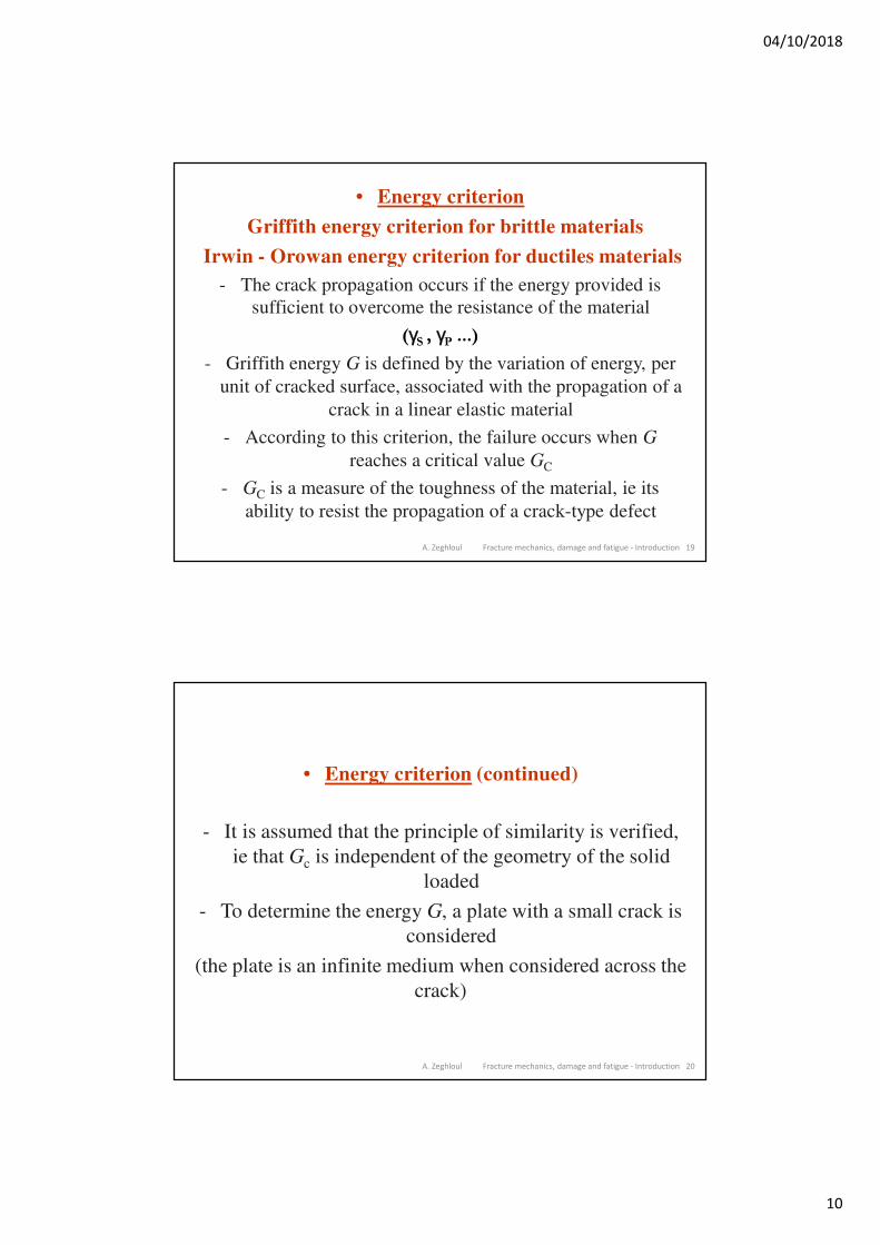
• Energy criterion
Griffith energy criterion for brittle materials
Irwin - Orowan energy criterion for ductiles materials
- The crack propagation occurs if the energy provided is
sufficient to overcome the resistance of the material
(γS , γP ...)
- Griffith energy G is defined by the variation of energy, per
unit of cracked surface, associated with the propagation of a
crack in a linear elastic material
- According to this criterion, the failure occurs when G
reaches a critical value GC
- GC is a measure of the toughness of the material, ie its
ability to resist the propagation of a crack-type defect
A. Zeghloul Fracture mechanics, damage and fatigue - Introduction 20
• Energy criterion (continued)
- It is assumed that the principle of similarity is verified,
ie that Gc is independent of the geometry of the solid
loaded
- To determine the energy G, a plate with a small crack is
considered
(the plate is an infinite medium when considered across the
crack)
04/10/2018
11
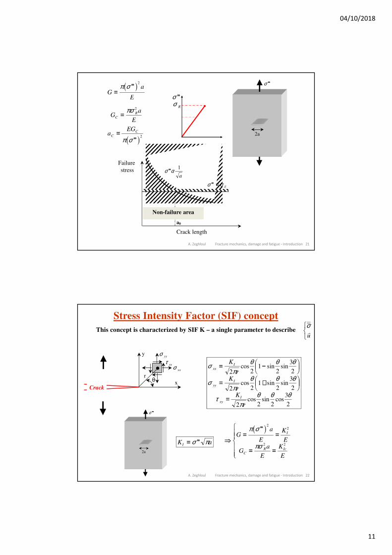
A. Zeghloul Fracture mechanics, damage and fatigue - Introduction 21
2a
σ ∞
Ga
E=
∞π σc h2
σ ∞
σ R
Ga
EC
R=πσ 2
aEG
C
C=∞π σc h2
Longueur de fissure
Contrainteà rupture
Zone de non rupture
σ σ∞ = E
σ α∞ 1
a
a0
Failure
stress
Crack length
Non-failure area
A. Zeghloul Fracture mechanics, damage and fatigue - Introduction 22
Stress Intensity Factor (SIF) concept
This concept is characterized by SIF K – a single parameter to describeσ�
u
RST
σπ
θ θ θ
σπ
θ θ θ
τπ
θ θ θ
xx
I
yy
I
xy
I
K
rK
rK
r
= −FHGIKJ
= +FHGIKJ
=
2 21
2
3
2
2 21
2
3
2
2 2 2
3
2
cos sin sin
cos sin sin
cos sin cos
2a
σ ∞
K aI = ∞σ π = =
= =
RS||
T||
∞
Ga
E
K
E
Ga
E
K
E
I
C
R Ic
π σ
πσ
c h2 2
2 2
σ xx
σ yy
τ xy
x
y
θr
Crack
04/10/2018
12
A. Zeghloul Fracture mechanics, damage and fatigue - Introduction 23
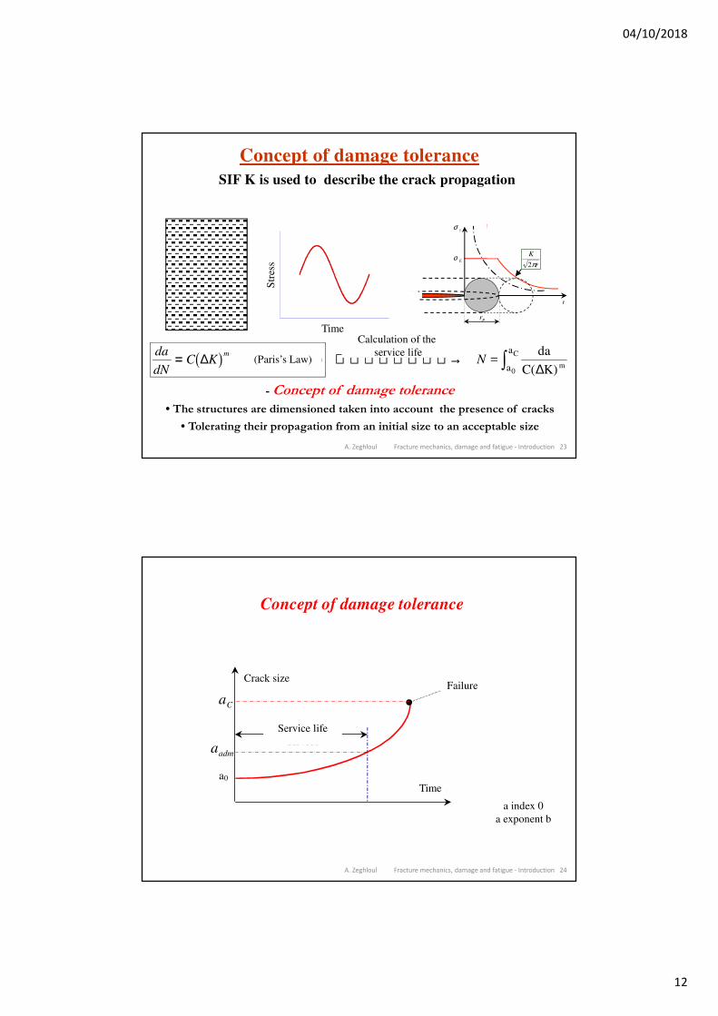
Concept of damage tolerance
SIF K is used to describe the crack propagation
rP
σ y
σ E
r
K
r2π
- Concept of damage tolerance
• The structures are dimensioned taken into account the presence of cracks
• Tolerating their propagation from an initial size to an acceptable size
da
dNC K
m= ∆b g (Loi de Paris)(Paris’s Law)Cacul de la durée de vie → zN =
da
C( K) m0
C
a
a
∆
Calculation of the
service life
Temps
Contr
ain
teS
tres
s
Time
A. Zeghloul Fracture mechanics, damage and fatigue - Introduction 24
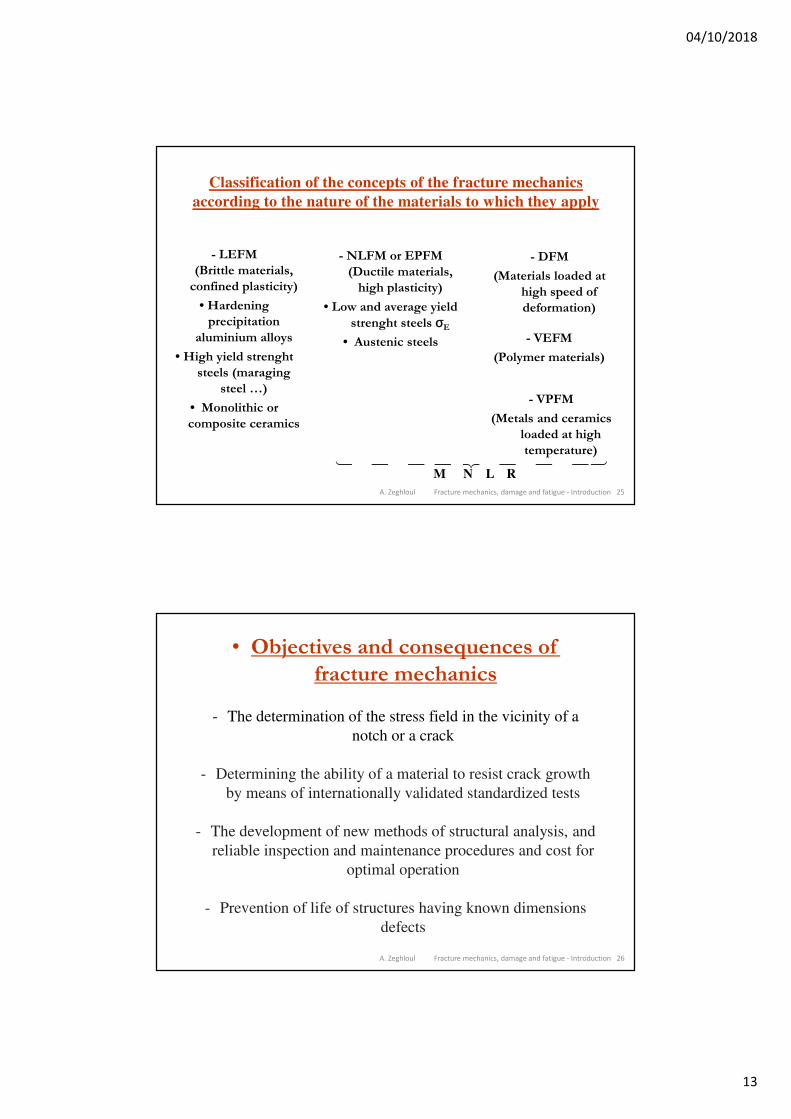
Concept of damage tolerance
Temps
Taille dudéfaut
Durée de vie en
service
Rupturebrutale
a0
aadm
aC
Crack sizeFailure
Service life
Time
a index 0
a exponent b
04/10/2018
13
A. Zeghloul Fracture mechanics, damage and fatigue - Introduction 25
Classification of the concepts of the fracture mechanics
according to the nature of the materials to which they apply
- LEFM
(Brittle materials,
confined plasticity)
• Hardening
precipitation
aluminium alloys
• High yield strenght
steels (maraging
steel …)
• Monolithic or
composite ceramics
- NLFM or EPFM
(Ductile materials,
high plasticity)
• Low and average yield
strenght steels σE
• Austenic steels
- DFM
(Materials loaded at
high speed of
deformation)
- VEFM
(Polymer materials)
- VPFM
(Metals and ceramics
loaded at high
temperature)
M N L R� �� � � �� � �
A. Zeghloul Fracture mechanics, damage and fatigue - Introduction 26
• Objectives and consequences of
fracture mechanics
- The determination of the stress field in the vicinity of a
notch or a crack
- Determining the ability of a material to resist crack growth
by means of internationally validated standardized tests
- The development of new methods of structural analysis, and
reliable inspection and maintenance procedures and cost for
optimal operation
- Prevention of life of structures having known dimensions
defects
04/10/2018
14
A. Zeghloul Fracture mechanics, damage and fatigue - Introduction 27
• Fatigue damage
Service structures are generally subject to cyclic mechanical and/or
thermal stresses. These stresses, although lower than the elastic limit
of the material, can lead to failure : it is the process of fatigue
damage.
This damage has two stages. Initially, a microcrack is initiated near a
stress concentration zone ; this initiation is followed by a crack
propagation at the microscopic scale, invisible to the naked eye.
Secondly, the crack propagates at the macroscopic scale to failure.
The fatigue life is therefore naturally decomposed during the
initiation period and the propagation period. For practical reasons,
the crack growth on the microscopic scale, ie cracking over a length
of some grains, is included in the initiation period.
A. Zeghloul Fracture mechanics, damage and fatigue - Introduction 28
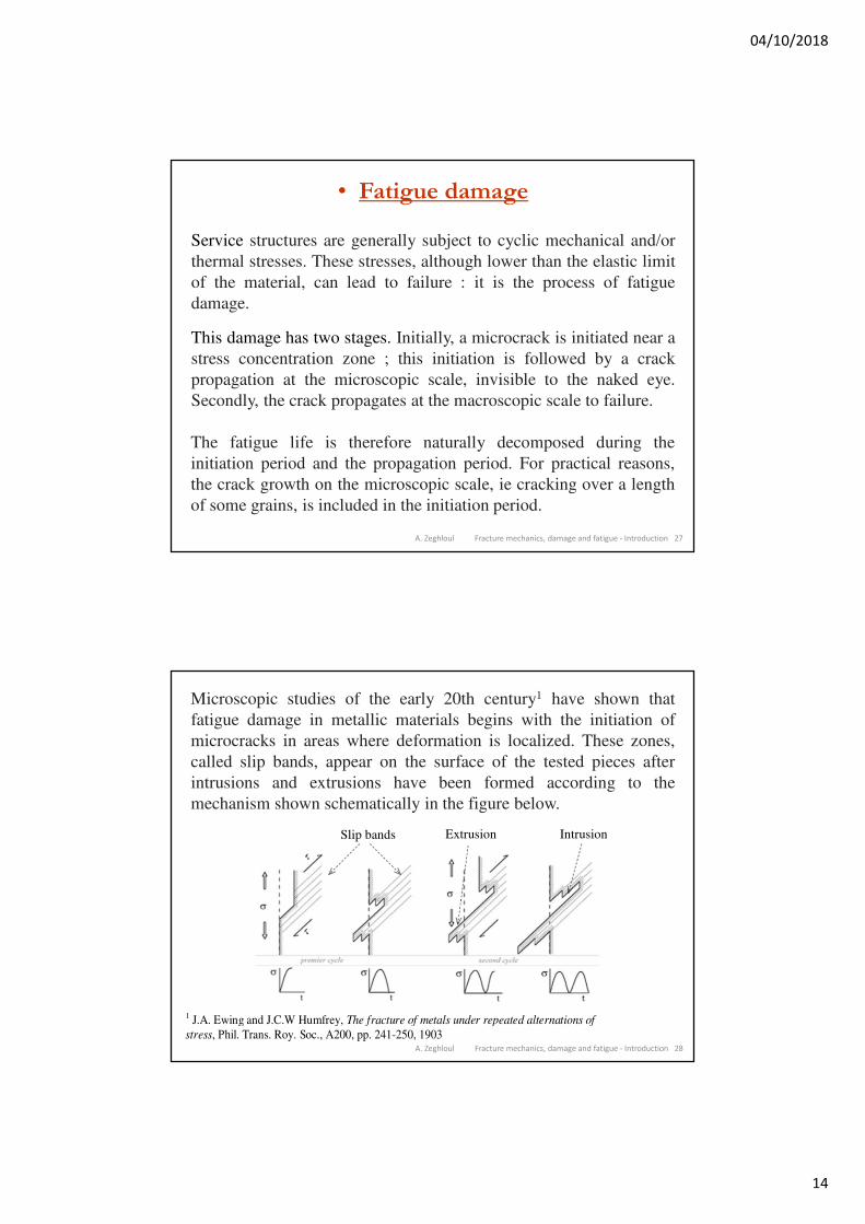
Microscopic studies of the early 20th century1 have shown that
fatigue damage in metallic materials begins with the initiation of
microcracks in areas where deformation is localized. These zones,
called slip bands, appear on the surface of the tested pieces after
intrusions and extrusions have been formed according to the
mechanism shown schematically in the figure below.
1 J.A. Ewing and J.C.W Humfrey, The fracture of metals under repeated alternations of
stress, Phil. Trans. Roy. Soc., A200, pp. 241-250, 1903
Slip bands Extrusion Intrusion
04/10/2018
15
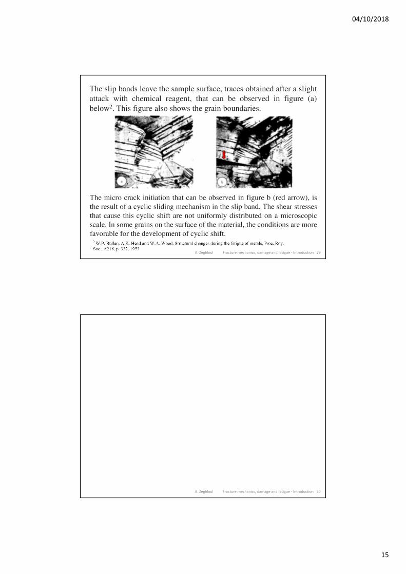
The slip bands leave the sample surface, traces obtained after a slight
attack with chemical reagent, that can be observed in figure (a)
below2. This figure also shows the grain boundaries.
The micro crack initiation that can be observed in figure b (red arrow), is
the result of a cyclic sliding mechanism in the slip band. The shear stresses
that cause this cyclic shift are not uniformly distributed on a microscopic
scale. In some grains on the surface of the material, the conditions are more
favorable for the development of cyclic shift.
A. Zeghloul Fracture mechanics, damage and fatigue - Introduction 29
A. Zeghloul Fracture mechanics, damage and fatigue - Introduction 30
04/10/2018
16
31
Master Mécanique-Matériaux-Structures-Procédés
Chapter 2 – Complex formulation of the plane theory
of elasticity
Prof. Abderrahim Zeghloul Université de Lorraine
Fracture Mechanics,
Damage and Fatigue
Contents
Plane theory of elasticity
Airy stress function
Complex representation of stresses and
displacements
Complex representation of resultant force and
moment
A. Zeghloul Fracture mechanics, damage and fatigue – Plane elasticity 32
04/10/2018
17
A. Zeghloul Fracture mechanics, damage and fatigue – Plane elasticity 33
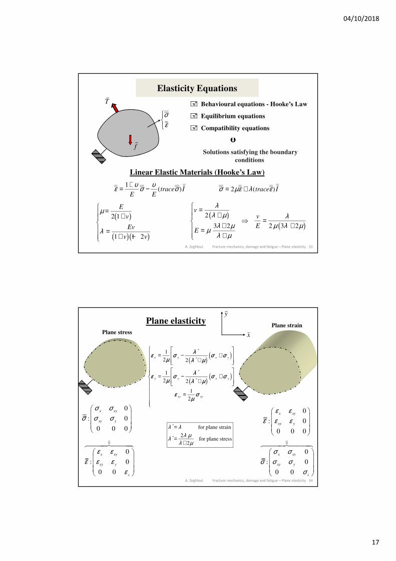
Elasticity Equations
Behavioural equations - Hooke’s Law
Equilibrium equations
Compatibility equations
Solutions satisfying the boundary
conditions
Linear Elastic Materials (Hooke’s Law)
ε υ σ υ σ= + −1
E Etrace I( ) σ µε λ ε= +2 ( )trace I
σεRST
�
T
�
f
µ
λ
=+
=+ −
RS||
T||
E
v
Ev
v v
2 1
1 1 2
b g
b gb g
v
E
v
E
=+
=++
RS||
T||
=+
λλ µ
µ λ µλ µ
λµ λ µ
2
3 2 2 3 2
b gb g
A. Zeghloul Fracture mechanics, damage and fatigue – Plane elasticity 34
Plane elasticity
0
: 0
0 0 0
x xy
xy y
σ σσ σ σ
0
: 0
0 0
x xy
xy y
z
ε εε ε ε
ε
���������
0
: 0
0 0
x xy
xy y
z
σ σσ σ σ
σ
���������
0
: 0
0 0 0
x xy
xy y
ε εε ε ε
εµ
σ λλ µ
σ σ
εµ
σ λλ µ
σ σ
εµ
σ
x x x y
y y x y
xy xy
= −+
+LNMM
OQPP
= −+
+LNMM
OQPP
=
R
S
|||||
T
|||||
1
2 2
1
2 2
1
2
*
*
*
*
c h d i
c h d i
*
*
for plane strain
2for plane stress
2
λ λλ µλ
λ µ
=
=+
x
�
y
Plane stress
Plane strain
04/10/2018
18
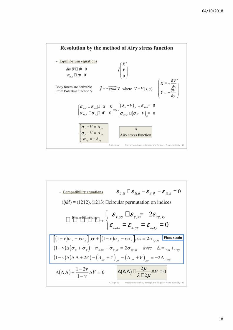
A. Zeghloul Fracture mechanics, damage and fatigue – Plane elasticity 35
Resolution by the method of Airy stress function
- Equilibrium equations
,
0
0ij j i
div f
f
σσ
+ =+ =
� ��
f
X
Y
0
F
HGGI
KJJ
where ( , )f grad V V V x y= − =��
XV
x
YV
y
= − ∂∂
= − ∂∂
F
H
GGG
I
K
JJJ
σ σσ σ
σ σ
σ σx x xy y
xy x y y
x x xy y
xy x yy
X
Y
V
V
, ,
, ,
, ,
,,
+ + =+ + =
RST|
− + =
+ − =
RS|T|
0
0
0
0
b gd i
σσσ
x yy
y xx
xy xy
V A
V A
A
− =− =
= −
RS|
T|
,
,
,
Airy stress function
A
Body forces are derivable
From Potential function V
A. Zeghloul Fracture mechanics, damage and fatigue – Plane elasticity 36
ε ε ε εij kl kl ij il jk jk il, , , ,+ − − = 0- Compatibility equations
( ) (1212), (1213) circular permutation on indicesijkl = +
, , ,Plane Elasticity
, , ,
2
0
x yy y xx xy xy
z xx z yy z xy
ε ε εε ε ε
+ =→ = = =
∆ ∆ Α ∆b g ++
=2
20
µλ µ
V
Plane strain
04/10/2018
19
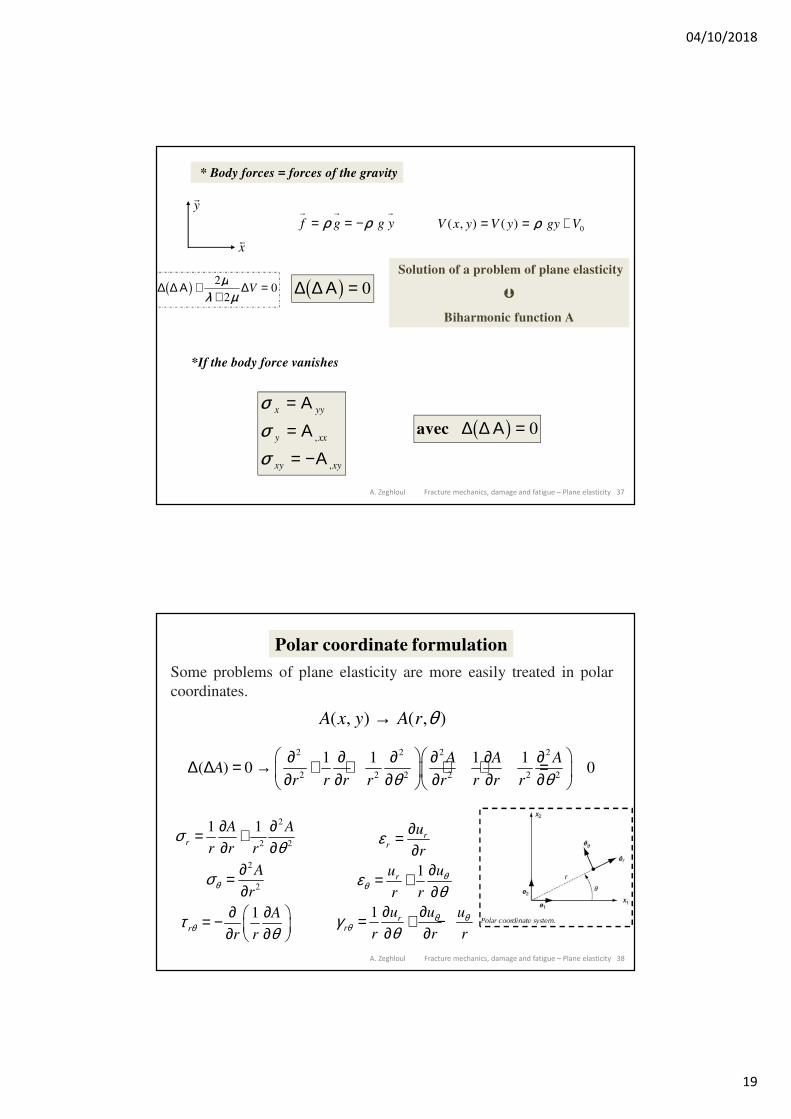
A. Zeghloul Fracture mechanics, damage and fatigue – Plane elasticity 37
* Body forces = forces of the gravity
f g g y→ → →
= = −ρ ρ
x
�
y
V x y V y gy V( , ) ( )= = +ρ 0
∆ ∆ Αb g = 0∆ ∆ Α ∆b g ++
=2
20
µλ µ
V
Solution of a problem of plane elasticity
Biharmonic function A
*If the body force vanishes
avec ∆ ∆ Αb g = 0
σσσ
x yy
y xx
xy xy
=
== −
Α
ΑΑ,
,
A. Zeghloul Fracture mechanics, damage and fatigue – Plane elasticity 38
Polar coordinate formulation
( , ) ( , )A x y A r θ→
Some problems of plane elasticity are more easily treated in polar
coordinates.
2 2 2 2
2 2 2 2 2 2
1 1 1 1( ) 0 0
A A AA
r r r r r r r rθ θ ∂ ∂ ∂ ∂ ∂ ∂∆ ∆ = → + + + + = ∂ ∂ ∂ ∂ ∂ ∂
2
2 2
2
2
1 1
1
r
r
A A
r r r
A
r
A
r r
θ
θ
σθ
σ
τθ
∂ ∂= +∂ ∂
∂=∂
∂ ∂ = − ∂ ∂
1
1
rr
r
rr
u
r
uu
r r
u uu
r r r
θθ
θ θθ
ε
εθ
γθ
∂=∂
∂= +∂
∂∂= + −∂ ∂
04/10/2018
20
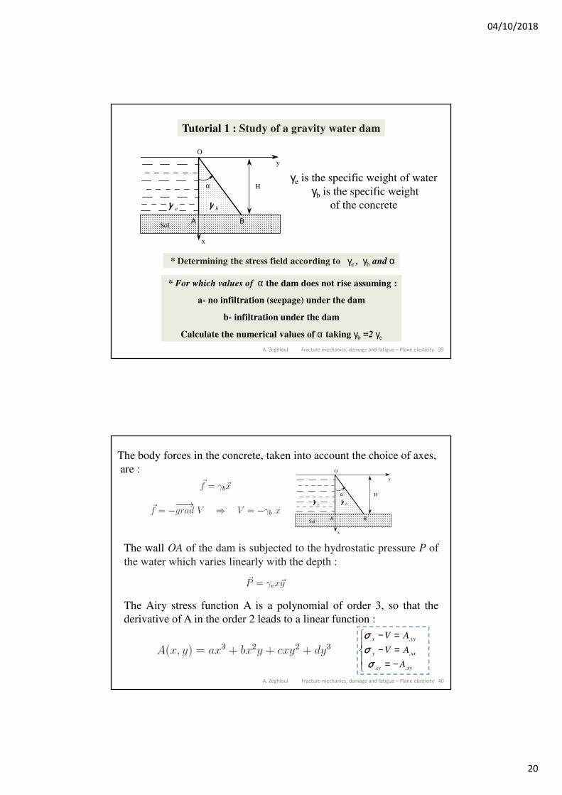
A. Zeghloul Fracture mechanics, damage and fatigue – Plane elasticity 39
Tutorial 1 : Study of a gravity water dam
A B
y
x
Hα
Sol
O
γ e γ b
* Determining the stress field according to γe , γb and α
* For which values of α the dam does not rise assuming :
a- no infiltration (seepage) under the dam
b- infiltration under the dam
Calculate the numerical values of α taking γb =2 γe
γe is the specific weight of water
γb is the specific weight
of the concrete
A. Zeghloul Fracture mechanics, damage and fatigue – Plane elasticity 40
The body forces in the concrete, taken into account the choice of axes,
are :
A B
y
x
Hα
Sol
O
γ e γ b
The wall OA of the dam is subjected to the hydrostatic pressure P of
the water which varies linearly with the depth :
The Airy stress function A is a polynomial of order 3, so that the
derivative of A in the order 2 leads to a linear function :
σσσ
x yy
y xx
xy xy
V A
V A
A
− =− =
= −
RS|
T|
,
,
,
04/10/2018
21
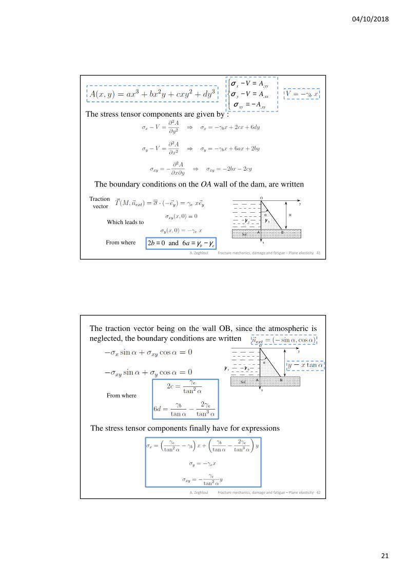
A. Zeghloul Fracture mechanics, damage and fatigue – Plane elasticity 41
The stress tensor components are given by :
σσσ
x yy
y xx
xy xy
V A
V A
A
− =− =
= −
RS|
T|
,
,
,
The boundary conditions on the OA wall of the dam, are written
Which leads to
From where 2 0 and 6 b eb a γ γ= = −
Traction
vector
A B
y
x
Hα
Sol
O
γ e γ b
A. Zeghloul Fracture mechanics, damage and fatigue – Plane elasticity 42
The traction vector being on the wall OB, since the atmospheric is
neglected, the boundary conditions are written
A B
y
x
Hα
Sol
O
γ e γ b
From where
The stress tensor components finally have for expressions