Embed Size (px)
Citation preview

Finite Element Analysis of a Novel Design for a Non-Migrating Biliary
Stent using Abaqus
By
Jared D. Mitchell
A Thesis Submitted to the Graduate Faculty of
VIRGINIA TECH – WAKE FOREST UNIVERSITY
SCHOOL OF BIOMEDICAL ENGINEERING & SCIENCES
In Partial Fulfillment of the Requirements
for the Degree of
MASTER OF SCIENCE
Biomedical Engineering
May 2016
Winston-Salem, North Carolina
Approved by:
Philip J. Brown, PhD, Advisor, Chair
Examining Committee:
Joel D. Stitzel, PhD
Clifford Howard Jr., MD

ii
ACKNOWLEDGEMENTS
I would first off like to thank my advisor, Dr. Philip Brown. His help and
guidance has provided me with a far greater ability to visualizing problems as well as
approach those design problems in an efficient and comprehensive manner. His
knowledge and ability to coherently convey that knowledge, make learning from him that
much easier.
The environment that exists in the VT - WFU Center for Injury Biomechanics
cannot be matched. The relationships between the students, faculty, and staff make
working simple.
Wake Forest Innovations has allowed me the opportunity to work on such great
projects such as this. I would like to thank Kenneth Russell, from WFI who has been
nothing but supportive in my collaborations between the biomedical engineering
department and Wake Forest Innovations.
I would also like to acknowledge my peers and friends that I have within the
program all of whom I have been able to go to for help or lean on for guidance. I would
also like to thank specifically Greg Gillispie for not only being a great friend but also
listening and helping me talk though problems.
I cannot thank the engineering department at Washington & Lee University
enough. Specifically Dr. Joel Kuehner and Dr. Jonathan Erickson each were integral in
developing my engineering knowledge as well as fostering my passion for engineering.
My family has been nothing but supportive throughout my academic career.
Without them and their support none of this would be possible.

iii
TABLE OF CONTENTS
List of Tables .......................................................................................................................... v
List of Figures ........................................................................................................................ vi
List of Abbreviations ............................................................................................................. xi
Abstract .................................................................................................................................1
CHAPTER I: INTRODUCTION & BACKGROUND .............................. 2
Biliary System Anatomy .........................................................................................................2
Causes for Biliary Stenting ......................................................................................................3
Early History of Biliary Drainage (Prior to 1978) ......................................................................3
Modern Biliary Stents: Plastic vs. Metallic ...............................................................................5
Chapter Summaries .............................................................................................................. 12 Chapter II: Finite Element Analysis of a Non-Migrating Biliary Stent Deployment ................... 12
Chapter III: Finites Element Analysis of Migration Reducing Hook Variations for a Novel Biliary
Stent .......................................................................................................................................... 12
Chapter IV: Parametric Study of a Deployment Hinge using Finite Element Analysis .............. 12
Chapter V: Summary of Research .............................................................................................. 12
References ........................................................................................................................... 13
CHAPTER II: FINITE ELEMENT ANALYSIS OF A NON-
MIGRATING BILIARY STENT DEPLOYMENT .................................16
1. Abstract ....................................................................................................................... 17
2. Introduction ................................................................................................................ 18
3. Methods ...................................................................................................................... 19
4. Results ......................................................................................................................... 24
5. Discussion .................................................................................................................... 32
6. Conclusion ................................................................................................................... 33
7. Acknowledgement ....................................................................................................... 34
8. References ................................................................................................................... 35

iv
CHAPTER III: FINITE ELEMENT ANALYSIS OF MIGRATION
REDUCING HOOK VARIATIONS FOR A NOVEL BILIARY STENT
.......................................................................................................................37
1. Abstract ....................................................................................................................... 38
2. Introduction ................................................................................................................ 39
3. Methods ...................................................................................................................... 40
4. Results ......................................................................................................................... 48
5. Discussion .................................................................................................................... 58
6. Conclusion ................................................................................................................... 59
7. Acknowledgement ....................................................................................................... 60
8. References ................................................................................................................... 61
CHAPTER IV: PARAMETRIC STUDY OF A DEPLOYMENT
HINGE USING FINITE ELEMENT ANALYSIS ...................................63
1. Abstract ....................................................................................................................... 64
2. Introduction ................................................................................................................ 65
3. Methods ...................................................................................................................... 66
4. Results ......................................................................................................................... 73
5. Discussion .................................................................................................................... 80
6. Conclusion ................................................................................................................... 82
7. Acknowledgement ....................................................................................................... 83
8. References ................................................................................................................... 84
CHAPTER V: SUMMARY OF RESEARCH ..........................................86
SCHOLASTIC VITA ..................................................................................87

v
LIST OF TABLES
Table 1: Stent-related complications in selected randomized controlled trials and single-
arm prospective studies.1 .................................................................................................. 10
Table 2: Reflects the Abaqus plastic deformation input table .......................................... 23
Table 3: Resultant Inflation Stiffnesses for the Stent Portion, Hook Portion, and Total
Stent factoring in prior or post hook out of plane bending. .............................................. 31
Table 4: Length of stents with respect to hook variation .................................................. 43
Table 5: Reflects the Abaqus plastic deformation input table .......................................... 45
Table 6: Hook Variation Deployment Hook and Mid-Stent Diameters ........................... 50
Table 7: Dimension of Slot Length and Side Joint Thickness when Slot Width is in “A”
State (0.06mm) .................................................................................................................. 68
Table 8: Dimension of Slot Length and Side Joint Thickness when Slot Width is in “B”
State (0.10mm) .................................................................................................................. 68
Table 9: Reflects the Abaqus plastic deformation input table .......................................... 69
Table 10: Pertinent values corresponding to each hinge type (All dimensional units are in
mm) ................................................................................................................................... 77

vi
LIST OF FIGURES
Figure 1: Anatomy of the Biliary System [3] ..................................................................... 2
Figure 2: A, Percutaneous pigtail stent placement; B, corresponding radiographic image
[4] ........................................................................................................................................ 5
Figure 3: Figure of plastic stents with anti-migration designs [2] ...................................... 7
Figure 4: Balloon Expansion of a metallic stent [1] ........................................................... 8
Figure 5: Self-Expandable Metal Stent naturally expanding to deployed position upon
retracting of sheath [1] ........................................................................................................ 9
Figure 6: Four-bar Linkage Hook Design ......................................................................... 20
Figure 7: Full Stent Model: A) Top view of the full stent with length dimensions. B)
Isometric of full stent. C) Side view of full stent with external diameter dimension. ...... 20
Figure 8: 1/24th of the full stent ....................................................................................... 21
Figure 9: Partitioning and Meshing of Non-Migration Stent. A) Stent depicting partition
locations. B) stent depicting overall hexahedral mesh...................................................... 22
Figure 10: Stent Material Model for Stainless Steel Grade 316: Mises Stress vs. Plastic
Strain ................................................................................................................................. 23
Figure 11: Stent Mesh showing specific node locations monitored for radial expansion
displacement comparison. ................................................................................................. 24

vii
Figure 12: Full Stent Model Deployed: ............................................................................ 25
Figure 13: Stent Body Displacement vs. Time: This shows the stent body's displacements
in the X, Y, & Z directions, as well as, the displacement magnitude with respect to time.
........................................................................................................................................... 26
Figure 14: Hook Tip Displacement vs. Time: This shows the hook tip's displacements in
the X, Y, & Z directions, as well as, the displacement magnitude with respect to time. . 26
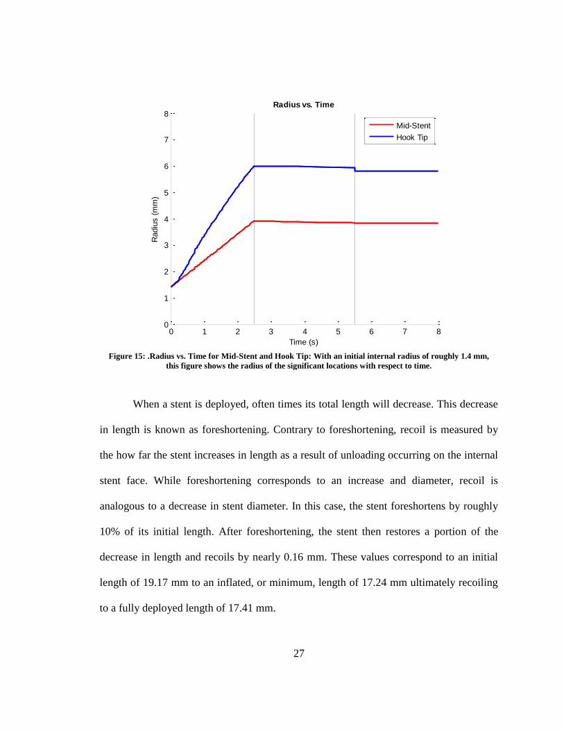
Figure 15: .Radius vs. Time for Mid-Stent and Hook Tip: With an initial internal radius
of roughly 1.4 mm, this figure shows the radius of the significant locations with respect
to time. .............................................................................................................................. 27
Figure 16: Foreshortening vs. Time: This reports the overall change in stent length with
respect to time. .................................................................................................................. 28
Figure 17: Stent Mises Stress with detail view of areas with stress/strain concentrations
(units of MPa) ................................................................................................................... 29
Figure 18: Stent Peak Equivalent Plastic Strain with detail view of areas with stress/strain
concentrations ................................................................................................................... 29
Figure 19: Mises Stress vs. Strain profiles for the interior arch of the stent body strut as
well as the internal arch of the hook hinge ....................................................................... 30
Figure 20: Force vs. Radial Displacement. This figure shows the force-displacement
profile for the inflation of the stent ................................................................................... 31
Figure 21: Four-bar Linkage Hook Design ....................................................................... 41

viii
Figure 22: A, Generic Hooked Stent; B, Flexible Tip Hooked Stent; C, Double Four-Bar
Hooked Stent ..................................................................................................................... 41
Figure 23: Generic Stent displaying measurement locations of hook portion, stent body,
and initial external diameter .............................................................................................. 42
Figure 24: Partitioning and Meshing of Stent Variations. A, Generic Stent Partitioning; B,
Associated generic stent hexahedral mesh; C, Flexible Hook Tip Stent Partitioning; D,
Associated flexible hook tip stent hexahedral mesh; E, Double Four-Bar Stent
Partitioning; F, Associated double four-bar stent hexahedral mesh ................................. 44
Figure 25: Stent Material Model for Stainless Steel Grade 316: Stress vs. Plastic Strain 46
Figure 26: Test comparison showing hook compression test step versus the axial tip test
step performed. ................................................................................................................. 47
Figure 27: Generic Stent Model Deployed: ...................................................................... 48
Figure 28: Flexible Hook Tip Stent Model Deployed: ..................................................... 49
Figure 29: Double Four-Bar Stent Model Deployed: ....................................................... 49
Figure 30: Displacement Magnitude vs. Time for all hook variations ............................. 50
Figure 31: Hook Variation Overlay .................................................................................. 50
Figure 32: Displacement vs. Time at middle of the stent and at the hook for all hook
variations during deployment. .......................................................................................... 51

ix
Figure 33: Displacement vs. Time at hook tip for all hook variations during the
compression and axial testing step of the simulation. ....................................................... 52
Figure 34: Generic Stent Deployed vs. Deformed: A) Fully Deployed Generic Stent; B)
Generic Stent under compressive load; C) Generic Stent hook after axial hook testing .. 53
Figure 35: Flexible Hook Tip Stent Deployed vs. Deformed: A) Fully Deployed Flexible
Hook Tip Stent; B) Flexible Hook Tip Stent under compressive load; C) Flexible Hook
Tip after axial hook testing ............................................................................................... 54
Figure 36: Double Four-Bar Stent Deployed vs. Deformed: A) Fully Deployed Double
Four-Bar Stent; B) Double Four-Bar Stent under compressive load; C) Double Four-Bar
hook after axial hook testing ............................................................................................. 55
Figure 37: Force vs. Displacement during different steps for the Generic Stent .............. 56
Figure 38: Force vs. Displacement during different steps for the Flexible Hook Tip Stent
........................................................................................................................................... 57
Figure 39: Force vs. Displacement during different steps for the Double Four-Bar Stent 57
Figure 40: Base hinge model with study parameters identified. ....................................... 66
Figure 41: Dimensions of all Hinge Conditions (NOTE: All dimensions are in mm and all
figures are not to scale) ..................................................................................................... 67
Figure 42: Stent Material Model for Stainless Steel Grade 316: Stress vs. Plastic Strain 69
Figure 43: A, Partitioning of the AAA Hinge; B, Mesh associated with the AAA Hinge 70

x
Figure 44: Figure depicting fixed end boundary condition and forces applied to nodes at
opposite end ...................................................................................................................... 71
Figure 45: Additional Test Setups for AAA Hinge. A: Strictly Moment Test Setup ; B:
Lateral Bending Test Setup ............................................................................................... 72
Figure 46: BBB Hinge. ..................................................................................................... 73
Figure 47: Moment vs. Angle for hinges with slot width in the ‘A’ state. ...................... 74
Figure 48: Moment vs. Angle for hinges with slot width in the ‘B’ state. ....................... 75
Figure 49: Linear Stiffness Model for initial and secondary deformation ........................ 76
Figure 50: Normalized Failure Angle and Mises Stress for each hinge type ................... 77
Figure 51: Initial and Secondary Stiffness for each hinge type ........................................ 78
Figure 52: A, deformation cause by force at nodes. B, deformation cause by rigid
cylinder boundary conditioning ........................................................................................ 78
Figure 53: Simulation performed on AAA Hinge to analyze lateral bending .................. 79
Figure 54: Mises Stress vs. Angle for Different Loading Mechanisms for the AAA Hinge
........................................................................................................................................... 79
Figure 55: Deformation at 55 degrees: A: Hinge with nodal force applied; B: Hinge with
rigid cylinder moment application; C: Generic Stent with balloon expansion. ................ 80
xi
LIST OF ABBREVIATIONS
CAD Computer Aided Design
CBD
Common Bile Duct
Co-Cr
Cobalt-Chromium
ERCP
Endoscopic retrograde cholangiopancreatography
FEA
Finite Element Analysis
MEMS
Microelectromechanical systems
MOJ
Malignant obstructive jaundice
PE
Polyethylene
PTBD
Percutaneous Transhepatic Biliary Drainage
PTFE
Polytetrafluoroethylene
PU
Polyurethane
RUC Repeating Unit Cell
SEMS
Self-Expandable Metal Stent
SS
Stainless Steel
WFI
Wake Forest Innovations

1
ABSTRACT
Biliary stenting is most frequently caused by an interruption in the ability to drain
bile into the duodenum. This obstructive jaundice is commonly a result of a stricture from
a tumor located at the pancreas’s head, peri-ampulary area, bile duct, or gall bladder.
Jaundice can also occur from anastomotic strictures which result from post-surgery
biliary complications. In order to restore patency, stenting of the biliary tree is performed
by means of endoscopic retrograde cholangiopancreatography (ERCP). There are two
main types of stents each having their respective advantages and disadvantages.
Unfortunately, nearly 30% of all biliary stents fail and require removal, exchange, or
intervention. One common mode of failure is migration, which occurs 17% of the time
with fully covered metallic stents.
The first part of this research presents deployment characteristics and behaviors of
a novel stent designed by Wake Forest Innovations (WFI). The overall design requires
evaluation during deployment to analyze its ability to return patency and identify
potential shortcomings. The second area of this thesis reports simulation results
performed on different variations of the anti-migration hooks developed for the novel
stent. These are the main component of the stent designed specifically to reduce
migration. Lastly, a parametric study of hinge dimensions was analyzed. The hinge is an
integral part of the anti-migration hook which allows the hook to not only deploy
properly, but also relieve stress that would otherwise occur at certain locations within the
stent.

2
Chapter I: Introduction & Background
BILIARY SYSTEM ANATOMY
The biliary system is comprised of the liver, gallbladder, and bile ducts. Its main
function is the production, storage, and secretion of bile [5, 6]. The most superior portion
of the biliary system is the liver. Bile production starts in the liver and enters the common
hepatic duct via the merging left and right hepatic ducts. The cystic duct, which drains
the gallbladder, meets with the hepatic duct which then forms the common bile duct
(CBD). After this junction, the common bile duct travels posteriorly behind the first part
of the small intestine, known as the duodenum, for a short distance where it is then
enveloped by the pancreas. The pancreatic duct joins the common bile duct in the
duodenal wall to form the Ampulla of Vater terminating in the duodenum after passing
through the Sphincter of Oddi [7].
Figure 1: Anatomy of the Biliary System [3]

3
CAUSES FOR BILIARY STENTING
Strictures occurring in the biliary system are often treated with biliary stenting [8-
12]. Most often bile duct strictures results from an unresectable tumor at the pancreas
head, peri-ampullary area, bile duct, or gall bladder [9, 13]. A surrounding tumor causes
increase pressure on the common bile duct resulting in a narrowing or obstruction of the
biliary tract. Strictures, although less frequently, may also occur from swelling as a result
of a liver transplant or cholecystectomy (gallbladder removal) [8]. Strictures resulting
from anastomosis are localized and short due to scaring [14].This narrowing or
obstruction of the biliary duct system is known as obstructive jaundice. Obstruction in the
biliary tract can lead to impaired immune defense leaving patients exposed to infection,
discomfort, and severe abdominal itching [9]. Stenting is performed as a palliative
treatment for patients to relieve this discomfort and pain [12, 13, 15]. There are both
malignant and benign cases associated with obstructive jaundice caused by unresectable
tumors [8-11]. Because of the increased severity of the malignant cases and the desire to
relieve the associated pain, biliary stenting is often seen in higher frequency with patients
diagnosed with malignant obstructive jaundice (MOJ) [9].
EARLY HISTORY OF BILIARY DRAINAGE (PRIOR TO 1978)
Prior to stenting within the biliary tract, clinicians would treat obstructive
jaundice by draining or bypassing the blocked duct [9]. Cholecystojejunostomy,
choledochojeunostomy, or hepaticojejunostomy are the three main bypass surgeries
associated with the biliary system for treatment of obstructive jaundice. These different

4
treatments are performed laproscopically depending on the location of the stricture. A
cholecystojejunostomy establishes a connection between the gallbladder and jejunum
(portion of the small intestine directly following the duodenum). A
choledochojeunostomy establishes a connection between the common bile duct and
jejunum. A hepaticojejunostomy establishes a connection between the liver and jejunum.
These surgical techniques can in some instances act as a curative treatment for benign
obstructive jaundice. They, however, still are associated with high morbidity and/or
mortality [16, 17].
With the inventions of the Chiba needle [18] and the duodenoscopes [19],
drainage of biliary obstruction became the treatment of choice in the 1970’s. Not only
was it reported to have a much higher success rate at 95% [20, 21], but it also was a less
invasive procedure. Percutaneous transhepatic biliary drainage (PTBD) was a way to
drain the biliary system both internally and externally (see Figure 2 below). This
procedure requires percutaneous entry of a catheter into the liver. The catheter then
travels through the hepatic duct and biliary ducts until reaching the duodenum. This
catheter allows not only for external flushing, but also allows for internal drainage into
the duodenum. Internal drainage is advantageous because it prevents significant bile loss
and electrolyte imbalance [9]. This procedure, however, requires much more maintenance
and intervention from clinicians. A similar method, endoscopic retrograde
cholangiopancreatography (ERCP), allows for drainage of the biliary system. ERCP does
so minimally invasively. It is performed by inserting an endoscope through the mouth
and through the gastrointestinal tract until the duodenal papilla can be located.
Nasobiliary tubes are then inserted into the common bile duct which allows bile drainage

5
to occur. While this is a minimally invasive technique to drain the bile duct, nasobiliary
tubes, like percutaneous catheters, are very pliable and can easily dislodge [9].
MODERN BILIARY STENTS: PLASTIC VS. METALLIC
In efforts to reduce the frequency of medical practitioner intervention, biliary
stents were developed and first used in 1978 by Burcharth and Pereiras [22, 23]. Biliary
stents allowed for internal drainage of bile from the liver and gallbladder into the
duodenum without the external loss. This mitigated the effect that external drainage has
on electrolyte imbalance and possible immune deficiencies. The first plastic stents were
made of varying materials. Polytetrafluoroethylene (PTFE or Teflon), polyethylene (PE),
and polyurethane (PU) were the most common polymers used [9]. All of these materials
possess different physical characteristics; mainly rigidity and melting point were
Figure 2: A, Percutaneous pigtail stent placement; B, corresponding radiographic image [4]

6
considered for material selection. Rigidity was a selection criterion because of its
correlation to overall stent patency. Melting point was used because many plastic stents
were melted and bent into a shape that would resemble an individual patient’s biliary
duct.
While plastic stents solved the need for doctors to routinely drain the biliary
system, it brought about other problems that required intervention. The two main reasons
for plastic stent dysfunction are migration and clogging which account for 15% and 80%
respectively of dysfunctional plastic stents [8]. In order to solve initial stent migration
three novel developments were made in the Tannenbaum Stent, the Cotton-Leung Stent,
and the Pigtail Stent. All of these stents had anti-migration characteristics associated with
the ends of the stent. The Tannenbaum Stent (Figure 3A below) prevented proximal
migration and mitigated distal migration. It prevented proximal migration due to the
flared ends that resembles Christmas tree branches (Tannenbaum is German for
Christmas tree, hence the name Tannenbaum stent). Similarly the Cotton-Leung Stent
(Figure 3B below) helped with migration due to its flared portion at each end. The
Tannenbaum and Cotton-Leung stents, however, do not perform as well in preventing
distal migration. Distal migration may occur because the anchoring flaps on the proximal
end are compressed by the surrounding biliary tissue and as a result are not as resistive to
migration. Distal migration, however, is not an uncommon occurrence. With distal
migration plastic stents are often spontaneously eliminated. The major advantage of the
Cotton-Leung stent versus the Tannenbaum stent is that the Cotton-Leung stent has a port
in the side of the tapered tip. This port allows for drainage even if the stent migrates
distally blocking the distal tip of the stent due to the duodenal wall. Pigtail stents (Figure

7
3C below), while they perform well with respect to migrating, are prone to bacteria
biofilm buildup which can result in stent clogging. Plastic stents in general are much
more prone to bacteria biofilm build up and have an overall short life patency.
Metallic stents provide a much more long term palliative treatment than plastic
stents and are therefore used to treat patients with a longer life expectancy [8]. Metallic
stents fall into two categories: balloon inflatable stents and self-expandable metal stent
(SEMS). The main difference between the two is their means of deployment. For balloon
inflatable stents, upon retracting of the sheath exposing the stent, a balloon is inflated
underneath the stent placing a pressure on the internal face of the stent causing it to
A B
C Figure 3: Figure of plastic stents with anti-migration
designs [2]
A) Tannenbaum Stent
B) Cotton-Leung Stent (Cook Medical, Winston-
Salem, NC)
C) Pigtail Stent
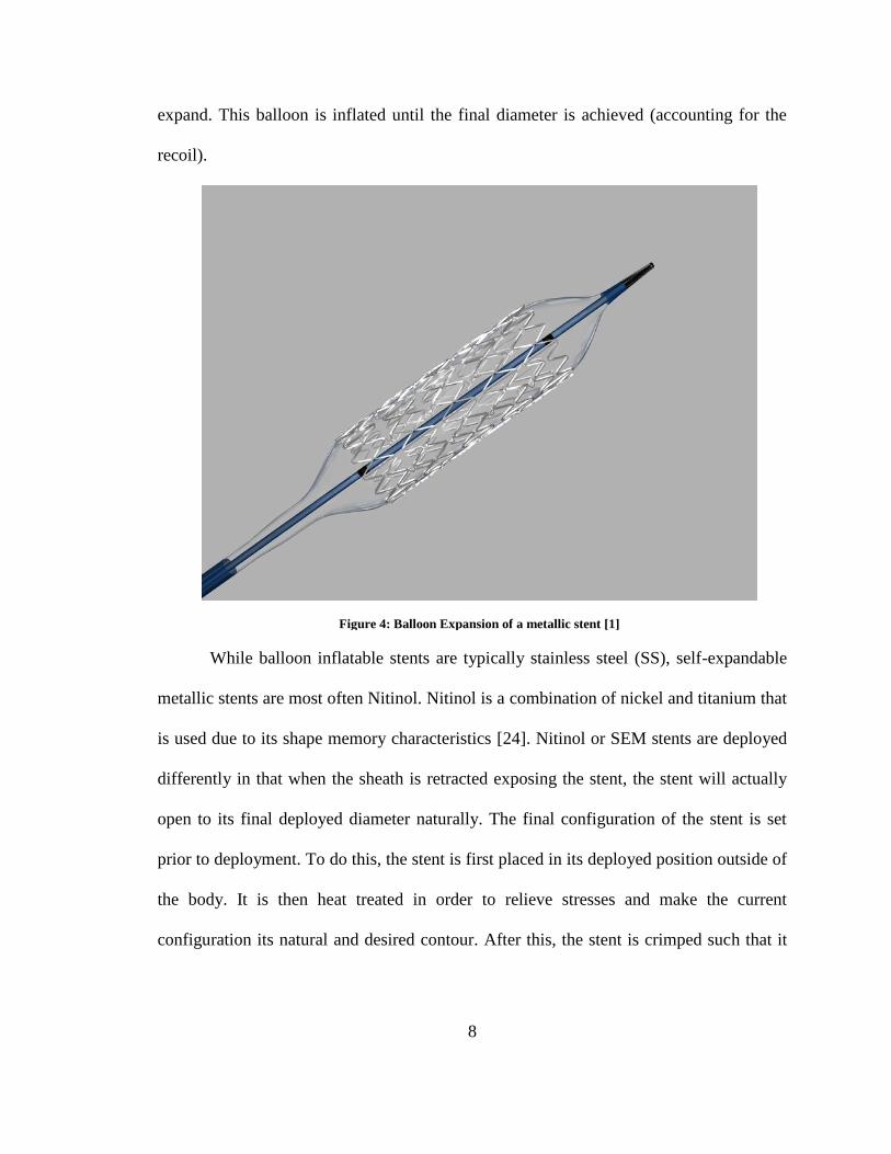
8
expand. This balloon is inflated until the final diameter is achieved (accounting for the
recoil).
While balloon inflatable stents are typically stainless steel (SS), self-expandable
metallic stents are most often Nitinol. Nitinol is a combination of nickel and titanium that
is used due to its shape memory characteristics [24]. Nitinol or SEM stents are deployed
differently in that when the sheath is retracted exposing the stent, the stent will actually
open to its final deployed diameter naturally. The final configuration of the stent is set
prior to deployment. To do this, the stent is first placed in its deployed position outside of
the body. It is then heat treated in order to relieve stresses and make the current
configuration its natural and desired contour. After this, the stent is crimped such that it
Figure 4: Balloon Expansion of a metallic stent [1]

9
can be loaded onto the catheter for insertion. This way, when deployed, the stent will
return to its desired, natural, and heat set position within the biliary duct.
Under balloon inflatable and self-expandable stents are uncovered, partially
covered and covered stents; each of which possesses different advantages and
disadvantages as well as reasons for implementation. Uncovered stents allow for tissue
ingrowth and overgrowth. This can be troublesome and lead to stent dysfunction
requiring retrieval. As seen in Table 1, often times with uncovered stents tissue ingrowth
(growth around the stent) and overgrowth (growth at the ends of the stent) are the cause
for stent dysfunction. 18% of uncovered stents fail in regard to tissue ingrowth and 7% as
Figure 5: Self-Expandable Metal Stent naturally expanding to deployed
position upon retracting of sheath [1]

10
a result of tissue overgrowth. This accounts for roughly 95% of the failed uncovered
stents. The remaining 5% come from clogging, 4%, and ‘other complications’ accounting
for the final 1% [8]. Covered stents solve the tissue in- and overgrowth problem. Covered
stents were developed with this intention such that they would not disturb the biliary
lining. With the covering, however, came migration as the common mode of dysfunction.
Partially covered stents were the middle ground between covered and uncovered but
seemingly only distributed the dysfunction cause between migration, clogging, tissue
ingrowth, and tissue overgrowth.
In order to fully understand the advantages and disadvantages of both material
types of biliary stents, the applications of each type of stent should be thoroughly
evaluated prior to drawing a conclusion. This is because different stents are associated
with different applications. For example you may not see as many stent migration cases
with plastic stents because plastic stents are often used in malignant cases in which the
life expectancy is not nearly as long a benign case [8]. Because of this short life
expectancy associated with benign cases (less than four months) [12], stent dysfunction
Table 1: Stent-related complications in selected randomized controlled trials and single-arm prospective studies.1

11
due to migration may be under reported. In this scenario a sufficient amount time may not
have elapsed to see if the stent would have failed due to migration.
Stent migration is a prevalent issue that, if solved, could reduce overall stent
dysfunction drastically. A fully covered stent that did not migrate could result in lowering
dysfunction from roughly 20% to only 5%. This would significantly reduce the frequency
a doctor would have to intervene in order to restore biliary patency. This reduced
interventions frequency and continued biliary patency, would bring with it a much higher
quality of life. It would also limit or eliminate other possible complications that could
arise from placement procedures or stent migration.
12
CHAPTER SUMMARIES
Chapter II: Finite Element Analysis of a Non-Migrating Biliary Stent Deployment
Finite element simulations were performed on the non-migrating stent in order to
evaluate pertinent parameters as well as overall efficacy of the design.
Chapter III: Finites Element Analysis of Migration Reducing Hook Variations for a
Novel Biliary Stent
Analysis of three different hook variations was tested to see how altered hooks would
respond to deployment along with compressive biliary forces that would be exerted by
the common bile duct.
Chapter IV: Parametric Study of a Deployment Hinge using Finite Element
Analysis
To evaluate the stress and strain relief associated with varying certain variables, a
parametric study was performed in order to evaluate the optimal hinge dimensions.
Chapter V: Summary of Research
This chapter provides an overview of the research completed in conjunction with this
thesis.

13
REFERENCES
1. Wilson-Cook Medical, I., Cook Medical: Biliary Stent. 2013: Winston-Salem.
2. Tamussino, E. Endoprosthesis. Products 2016 [cited Critical Care Prosthesis ];
Available from: http://www.tamussino.com.br/pt/filtro.php?idFiltro=60.
3. College, W.C.M., Biliary Systen, ei_0054.gif, Editor. 2015: New York.
4. Medicine, J.H., Chronic Pancreatitis. 2016, Gastroenterology & Hepatology.
5. Dodds, W.J., W.J. Hogen, and J.E. Green, Motility of the Biliary System.
Handbook of Physiology: The Gastrointestinal System. Vol. 1. 1989, Bethesda:
American Physiological Society.
6. Funch-Jensen, P. and N. Ebbenhoj, Sphincter of Oddi Motility. Scandinavian
Journal Gastroenterol, 1996. 31(216): p. 46-51.
7. Dowdy, G.S., Jr., G.W. Waldron, and W.G. Brown, Surgical anatomy of the
pancreatobiliary ductal system. Observations. Arch Surg, 1962. 84: p. 229-46.
8. Dumonceau, J.M., et al., Biliary stenting: indications, choice of stents and results:
European Society of Gastrointestinal Endoscopy (ESGE) clinical guideline.
Endoscopy, 2012. 44(3): p. 277-98.
9. Leung, J., Self-Expandable Stents in the Gastrointestinal Tract, in Self-Expandabl
Stents in the Gastrointestinal Tract, R. Kozarek, T. Baron, and H.-Y. Song,
Editors. 2013, Springer: New York. p. 15-31.
10. Lammer, J. and K. Neumayer, Biliary drainage endoprostheses: experience with
201 placements. Radiology, 1986. 159(3): p. 625-9.
11. Mueller, P.R., et al., Biliary stent endoprosthesis: analysis of complications in
113 patients. Radiology, 1985. 156(3): p. 637-9.

14
12. Dumonceau, J.M., et al., Biliary stents: models and methods for endoscopic
stenting. Endoscopy, 2011. 43(7): p. 617-26.
13. Donelli, G., et al., Plastic biliary stent occlusion: factors involved and possible
preventive approaches. Clin Med Res, 2007. 5(1): p. 53-60.
14. Williams, E.D. and P.V. Draganov, Endoscopic management of biliary strictures
after liver transplantation. World J Gastroenterol, 2009. 15(30): p. 3725-33.
15. Gouma, D.J., Stent versus surgery. HPB (Oxford), 2007. 9(6): p. 408-13.
16. Porter, E.A., Carcinoma of the pancreas. N Z Med J, 1970. 71(456): p. 288-92.
17. Bufkin, W.J., P.E. Smith, and E.T. Krementz, Evaluation of palliative operations
for carcinoma of the pancreas. Arch Surg, 1967. 94(2): p. 240-2.
18. Okuda, K., Thin needle percutaneous transhepatic cholangiography - historical
review. Endoscopy, 1980. 12(1): p. 2-7.
19. Oi, I., et al., [New method for the diagnosis of pancreatic and biliary tract
diseases; technics and results of endoscopic radiography of the pancreas and the
bile ducts]. Naika, 1970. 26(2): p. 325-39.
20. Ferrucci, J.T., Jr., P.R. Mueller, and W.P. Harbin, Percutaneous transhepatic
biliary drainage: technique, results, and applications. Radiology, 1980. 135(1): p.
1-13.
21. Ring, E.J., et al., Therapeutic applications of catheter cholangiography.
Radiology, 1978. 128(2): p. 333-8.
22. Burcharth, F., A new endoprosthesis for nonoperative intubation of the biliary
tract in malignant obstructive jaundice. Surg Gynecol Obstet, 1978. 146(1): p.
76-8.

15
23. Pereiras, R.V., Jr., et al., Relief of malignant obstructive jaundice by percutaneous
insertion of a permanent prosthesis in the biliary tree. Ann Intern Med, 1978.
89(5 Pt 1): p. 589-3.
24. Song, H.-Y., J.H. Kim, and C.J. Yoon, Self-Expandable Stents in the
Gastrointestinal Tract, in Self-Expandabl Stents in the Gastrointestinal Tract, R.
Kozarek, T. Baron, and H.-Y. Song, Editors. 2013, Springer: New York. p. 35-49.

16
Chapter II: Finite Element Analysis of a Non-Migrating Biliary
Stent Deployment
Jared Mitchell1, Clifford Howard Jr.
2, Philip J. Brown
1
1Virginia Tech – Wake Forest University Center for Injury Biomechanics,
Winston-Salem, NC
2 Wake Forest Baptist Health Medical Center, Winston-Salem, NC
17
1. ABSTRACT
Finite element simulations were performed on a novel design for a non-migrating
biliary stent in order to understand deployment characteristics as well as mechanical
properties associated with the stent. Simulations were performed using Abaqus/Standard
and the stent model was imported from SolidWorks using the SolidWorks Associative
Interface. Due to radial and planar symmetry, one-twenty-fourth of the complete stent
was modelled. The use of this recurring section allows for symmetry constraints and
boundary conditions to be implemented such that the simulations will act as if a complete
stent were present. An elasto-plastic stainless steel material model was developed which
corresponded to the stent. A rigid cylinder expansion was incorporated to act as a balloon
would in a balloon-inflatable stent deployment. As the cylinder expanded the general
contact algorithm set up in Abaqus caused an interaction between the cylinder (balloon)
and the stent. From this interaction arose contact force applied to the stent resulting in
stent expansion and full deployment into its desired position. Simulations were set up to
have three steps: inflation, deflation, and settling. This would account for how a balloon
inflatable stent is practically inserted. Having these three steps would also allow for
monitoring of radial displacement, foreshortening, and recoil. In addition to analyzing
these three parameters, stent stiffness and stress concentration areas were are also
reported.

18
2. INTRODUCTION
Obstructive jaundice can leave a patient with impaired immune defenses and
predisposed to bacterial infection [1]. Strictures resulting in obstructive jaundices are
most often caused by tumors located at the pancreas head [1-6]. Anastomotic strictures
may also occur from swelling as a result of a liver transplant or cholecystectomy
(gallbladder removal) [2]. Strictures resulting from anastomosis are localized and short
due to scaring at the Sphincter of Oddi (where the CBD meets the duodenum) [7].
Narrowing of the bile duct can cause deficiencies in the secretion of bile into the
duodenum (the first part of the small intestine following the stomach). In instances with
biliary duct complications, stenting has become a common practice [6].
Stents were designed and developed to keep vessels within the body open [8].
Biliary stent implementation is often times placed by taking the delivery system through
the mouth, past the stomach and finding the major ampulla (Ampulla of Vater). This
process is known as Endoscopic retrograde cholangiopancreatography (ERCP) [3]. There
are two methods for delivery each associated with a certain metallic stent type. For
balloon expandable stents, the delivery system also contains a catheter, the stent, and the
balloon. For self-expandable metal stents (SEMS) the balloon is not needed (however,
can be used for dilation). Upon catheter insertion and proper placement location found,
the sheath of the catheter is retracted and the balloon is inflated underneath the stent
causing a pressure on the internal face of the stent. This pressure expands the stent. After
the predetermined radius for the stent is reached, the balloon is then deflated and, along
with the catheter, is removed leaving only the stent [3, 9].
19
This chapter will report on finite element (FE) simulations resembling this
deployment process. Simulations were performed on the non-migrating stent to better
evaluate the unique deployment geometry and understand mechanically how the stent
performs. This will be analyzed by monitoring the stiffness of the stent during inflation
and deflation of the balloon such that all steps of the deployment have been included.
3. METHODS
Stent, Balloon, & Compression Sheet Modeling:
Development of the non-migration stent was performed using Dassault Systemes’
SolidWorks 2015. SolidWorks is a commonly used 3D modelling software package that
allows the user to develop models for prototyping or simulation. This use of computer
software is known as computer-aided design (CAD) [10]. The hook design is novel to
Wake Forest Innovation and is located at either end of the stent body. The concept behind
the hook deployment stems from a simple four-bar linkage configuration. In this design,
as the stent diameter increases, the mid-hook support will be drawn opposite of the
foreshortening direction and, given the hook structure, cause out-of-plane bending. The
complete stent has an overall length of 19.18 mm. There are twelve total hooks (six on
the proximal side and six on the distal side). The two hook sections on either side occupy
9.18 mm (4.59 mm each) and the stent body section occupies the remaining 10.00 mm of
the 19.17 mm. The stent was designed with an initial diameter of 3.00 mm to fit in a
roughly 10 French catheter.

20
A
C B
Figure 7: Full Stent Model: A) Top view of the full stent with length dimensions. B) Isometric of full stent.
C) Side view of full stent with external diameter dimension.
Figure 6: Four-bar Linkage Hook Design

21
Using the common knowledge of repeating unit cells (RUCs), this allowed us to
model only one twenty-fourth of the stent and balloon. A one twenty-fourth section was
reached due to the inherent symmetry that exists within the stent. First, the distal end
mirrors the proximal end. There is also radial symmetry in that each hook is identical to
one another. Lastly, the hook itself is symmetric about the mid-plane resulting in a 1/24th
section. This symmetry had the added benefit in that it greatly reduced computational
requirements and simulation time.
All of the CAD, however, was not done using SolidWorks. The balloon was
modelled using Abaqus’ modeling package. While the stent was modeled as a solid body,
the balloon was modeled as a surface.
Simulation Assembly Set-Up: Constraints, Meshing, and Boundary Conditions:
The simulation software used was Simulia’s Abaqus/CAE version 6.14. In order
to import the stent model from SolidWorks into Abaqus, a SolidWorks/Abaqus “plug-in”
was used. This allowed for minor design optimization to be made in SolidWorks, while
still preserving the added features developed in Abaqus (i.e. partitioning, meshing,
constraints, boundary conditions, and material assignments).
Figure 8: 1/24th of the full stent

22
The stent is meshed using hexahedral elements. The one twenty-fourth section of
the stent is comprised of 6864 elements and 10965 nodes of Abaqus’ C3D8R type. This
type is an 8-node linear brick with a reduced integration and hourglass control. In order to
generate an appropriate mesh the stent had to be partitioned. This was done in order to
eliminate the possibility of distorted element. Edges of the stent were also seeded such
that at no point is there a cross section with less than 3 by 3 elements. This will allow for
appropriate monitoring of stresses in all modes of bending.
Sdlkfjsd’f
The stent material model was resembled after stainless steel 316 [11]. An elasto-
plastic material model was used with the following parameters: Density = 8000 kg/m3 ;
Young’s Modulus = 193 GPa ; Poisson’s Ratio = 0.27 ; Yield Strength = 193 MPa ; See
Table 2 and Figure 10 for parameters associated with plastic deformation.
Figure 9: Partitioning and Meshing of Non-Migration Stent. A) Stent depicting partition locations. B) stent
depicting overall hexahedral mesh
A
B

23
Table 2: Reflects the Abaqus plastic deformation input table
Yield Stress (MPa) Plastic Strain
193 0
193 0.003
316 0.0037
400 0.03
550 0.14
700 0.5
701 1
0 0.1 0.2 0.3 0.4 0.5 0.6 0.7 0.8 0.9 1100
200
300
400
500
600
700
800
Str
ess (
MP
a)
Plastic Strain
SS 316: Stress vs. Plastic Strain
Figure 10: Stent Material Model for Stainless Steel Grade 316: Mises Stress vs. Plastic Strain

24
The balloon was attributed a material model that was ten times as rigid as the
stainless steel 316 material model. This was used as a “dummy material” simply to run
the simulation. Because of the boundary condition that was attributed to the balloon
model and the fact that the balloon was not being analyzed a material was only necessary
to have the simulation run properly.
In order to simulate balloon inflation, a rigid cylinder expansion was attributed to
the nodes of the balloon surface [12]. This BC is applied to a 1.0 mm/s velocity radially
outward from the balloon’s central axis for 2.5 s. Following inflation, a deflation occurs
drawing the balloon back in. This occurs over 3 s with a -0.75 mm/s velocity boundary
control. After deflation, a settling step occurs for 2.5 s (0 mm/s velocity control on the
balloon). Displacements, stresses, and strains were monitored for each element in the
model throughout the entire simulation. Contact forces occurring between the internal
face of the stent and the balloon surface were reported.
4. RESULTS
The stent deploys as expected. Upon balloon inflation, the resultant stent diameter
increases. As the stent diameter increases, the hooks tips displace farther than the stent
body portion.
Figure 11: Stent Mesh showing specific node locations monitored for radial expansion displacement comparison.

25
In order to comprehend stent deployment, displacements were reported for all
elements of the full stent with the main focus on the stent body versus hook tip
displacements/coordinates (See Figure 12 above for corresponding locations). The
maximum displacement of 2.506 mm for the stent body occurs at the end of balloon
inflations. Simultaneously, the hook tip reaches its maximum displacement of 4.669 mm.
With an initial stent diameter of 3 mm, these displacements correspond to diameters of
roughly 8 mm and 12 mm respectively.
Figure 12: Full Stent Model Deployed:
A, Top view of the full stent after deployment.
B, Side view of full stent after deployment.
C, Isometric of full stent after deployment.
A B
C

26
0 1 2 3 4 5 6 7 8-0.5
0
0.5
1
1.5
2
2.5
3
Dis
pla
cm
ent
(mm
)
Time (s)
Stent Body Displacement vs. Time
X-Direction
Y-Direction
Z-Direction
Magnitude
Figure 13: Stent Body Displacement vs. Time: This shows the stent body's displacements in the X, Y, & Z
directions, as well as, the displacement magnitude with respect to time.
0 1 2 3 4 5 6 7 8-1
0
1
2
3
4
5
Dis
pla
cm
ent
(mm
)
Time (s)
Hook Tip Displacement vs. Time
X-Direction
Y-Direction
Z-Direction
Magnitude
Figure 14: Hook Tip Displacement vs. Time: This shows the hook tip's displacements in the X, Y,
& Z directions, as well as, the displacement magnitude with respect to time.
27
When a stent is deployed, often times its total length will decrease. This decrease
in length is known as foreshortening. Contrary to foreshortening, recoil is measured by
the how far the stent increases in length as a result of unloading occurring on the internal
stent face. While foreshortening corresponds to an increase and diameter, recoil is
analogous to a decrease in stent diameter. In this case, the stent foreshortens by roughly
10% of its initial length. After foreshortening, the stent then restores a portion of the
decrease in length and recoils by nearly 0.16 mm. These values correspond to an initial
length of 19.17 mm to an inflated, or minimum, length of 17.24 mm ultimately recoiling
to a fully deployed length of 17.41 mm.
Figure 15: .Radius vs. Time for Mid-Stent and Hook Tip: With an initial internal radius of roughly 1.4 mm,
this figure shows the radius of the significant locations with respect to time.
0 1 2 3 4 5 6 7 80
1
2
3
4
5
6
7
8
Radiu
s (
mm
)
Time (s)
Radius vs. Time
Mid-Stent
Hook Tip

28
In addition to displacements, stress concentrations were monitored. Stress and
strain management is important in stents mainly because the structures that comprise the
stent are often times only microns thick. It is important to make sure that the stent will
not fail upon deployment [13]. Hence why there exist extensive simulations prior to
prototyping and testing. In order to determine how our stent would perform, we probed
areas of high stress and strain. There areas of highest values occurred on the interior arch
of the stent body strut as well as the internal arch of the hook hinge.
Figure 16: Foreshortening vs. Time: This reports the overall change in stent length with
respect to time.
0 1 2 3 4 5 6 7 80
0.5
1
1.5
2
2.5
Change in S
tent
Length
(m
m)
Time (s)
Change in Stent Length vs. Time

29
Figure 17: Stent Mises Stress with detail view of areas with stress/strain concentrations (units of MPa)
Figure 18: Stent Peak Equivalent Plastic Strain with detail view of areas with stress/strain concentrations

30
In order to evaluate the stiffness of the stent during deployment, contact forces
were monitored during the overall loading of the stent (inflation). Stiffness looks at the
force required to displace the stent radially (see Figure 20 below). As you can see from
Figure 20, the stent has a drastic change in force at roughly 0.27s. At this point the hook
begins to bend out of plane. Because of this, two stiffnesses have been attributed to each
feature: a pre- and post-hook out of plane bending stiffness (see Table 3).
Figure 19: Mises Stress vs. Strain profiles for the interior arch of the stent body strut as well as the internal
arch of the hook hinge
0 0.05 0.1 0.15 0.2 0.25 0.3 0.350
100
200
300
400
500
600
700
Strain
Str
ess (
MP
a)
Stress vs. Strain
Hook Hinge
Stent Strut
SS 316 Tensile Strength

31
Table 3: Resultant Inflation Stiffnesses for the Stent Portion, Hook Portion, and Total Stent factoring in prior or
post hook out of plane bending.
Pre-Bending Stiffness
(N/mm)
Post-Bending Stiffness
(N/mm)
Stent Portion 23.43 2.18
Hook Portion 17.49 1.85
Total Stent 40.49 4.03
Figure 20: Force vs. Radial Displacement. This figure shows the force-displacement profile for the inflation
of the stent
0 0.5 1 1.5 2 2.5 30
2
4
6
8
10
12
14
16
18
Displacement (mm)
Forc
e (
N)
Force vs. Radial Displacement
Stent Portion Inflation
Hook Portion Inflation
Inflation Total

32
5. DISCUSSION
In terms of methodology, a rigid cylinder expansion of the balloon model is a
sufficient means for the balloon inflation. Research has also gone into the modeling
behind the different techniques for balloon inflation [12]. Even though rigid cylinder
expansion “can be used interchangeably” (Gervaso et. al) with an internal balloon
pressure inflation [12], a pressure simulation may be a possible next step for this stent.
Given the novel design of the stent notion that the hook requires less pressure to deploy
(Figure 20), applying a pressure the internal face of the balloon model may yield a
different deployment shape as well as different loading parameters of the stent structures.
A pressure simulation may be able to account for these variations.
This stent is of smaller length and larger diameter as it relates to other biliary
stents. It is stated in literature that smaller length and larger diameter stents are more
prone to migration [6, 9, 14]. The rationale behind our dimensions was done
intentionally. Solving migration with respect to anastomotic stricture is the more difficult
that other biliary strictures because of the short landing zone [7]. Not only would this
stent solve migration with anastomic strictures, but features could be scaled and/or
augmented such that this stents could meet the needs of other applications.
One important figure to note is Figure 20. This figure helps show the relative
stiffnesses of the stent body versus the hook portion. There is one discontinuity within the
inflation traces. The discontinuity which occurs at roughly 0.27 s is due to the start of the
hook bending out of plane. Initially the hook portion acts just like the stent, only
expanding as a cylinder. Looking at Figure 14, for the first quarter of a second the radii
follow the same path. After that, however, the hook tip radius increases at a much faster

33
rate. This local maximum occurring at roughly a quarter of a second in Figure 20 is due
to the resistance of the four-bar linkage to brake from its 2D motion and include bending
out of plane. The reason a drop in overall force can also be seen in the stent body portion
is due to the joined relationship that exists. As the stent portion inflates it will foreshorten
and draw the hook portion closer to the mid-plane. Because the radial increase and out of
plane bending are coupled, this decrease in resistance to bend out of plane is seen in the
reduced force required to continue to inflate the overall stent.
The stress concentration that occur in the stent, primarily in the hinge portion,
approach or have already passed the tensile strength of the stent. The tensile strength for
annealed stainless steel 316 is 586 MPa [15, 16]. With this material the stent would fail
and not be able to pass testing for implementation. There are two ways to solve this. One
solution is to improve and alter features such that the stresses are less prominent in the
specified stress-strain concentration areas. The second way to eradicate this problem
would be to switch the material used. In this case, a cobalt chromium alloy may be a
viable solution. Co-Cr alloys are relatively stiffer and comes with a much higher tensile
strength ranging from 951 – 1220 MPa [15-17]. This material may not only prevent the
stent from failing, but also help in added stiffness which would increase the overall
rigidity of the stent.
6. CONCLUSION
The hooks of the stent deploy as desired. The ultimate goal was to achieve a hook
design that would displace the proximal and distal ends of the stent greater than the
middle. This also wanted to be done in such a fashion that it would reduce the ability for

34
the stent to migration. With this deployment mechanism, this would prevent migration
within the common bile duct and reduce the need for intervention of medical
practitioners. This stent could not only be used in the common bile duct but also be
modified and used to solve migration issues occurring elsewhere in the body. This stent is
an innovative design that is vastly different from current biliary stents.
7. ACKNOWLEDGEMENT
Funding for this project was provided by Wake Forest Innovations. Additional help
and support was provided by the Virginia Tech – Wake Forest University Center for
Injury Biomechanics.

35
8. REFERENCES
1. Leung, J., Self-Expandable Stents in the Gastrointestinal Tract, in Self-Expandabl
Stents in the Gastrointestinal Tract, R. Kozarek, T. Baron, and H.-Y. Song,
Editors. 2013, Springer: New York. p. 15-31.
2. Dumonceau, J.M., et al., Biliary stenting: indications, choice of stents and results:
European Society of Gastrointestinal Endoscopy (ESGE) clinical guideline.
Endoscopy, 2012. 44(3): p. 277-98.
3. Dumonceau, J.M., et al., Biliary stents: models and methods for endoscopic
stenting. Endoscopy, 2011. 43(7): p. 617-26.
4. van Boeckel, P.G., F.P. Vleggaar, and P.D. Siersema, Plastic or metal stents for
benign extrahepatic biliary strictures: a systematic review. BMC Gastroenterol,
2009. 9: p. 96.
5. Lammer, J. and K. Neumayer, Biliary drainage endoprostheses: experience with
201 placements. Radiology, 1986. 159(3): p. 625-9.
6. Mueller, P.R., et al., Biliary stent endoprosthesis: analysis of complications in
113 patients. Radiology, 1985. 156(3): p. 637-9.
7. Williams, E.D. and P.V. Draganov, Endoscopic management of biliary strictures
after liver transplantation. World J Gastroenterol, 2009. 15(30): p. 3725-33.
8. Hontz, R.A., M.D. Tripp, and L.P. Kline, Stents keep occluded vessels open. RN,
1991. 54(3): p. 50-4.
9. Chaurasia, O.P., et al., Endoscopic techniques for retrieval of proximally migrated
biliary stents: the Amsterdam experience. Gastrointest Endosc, 1999. 50(6): p.
780-5.
36
10. Bonsignore, C., Open Stent Design, ed. C. Commons. 2011, Fremont, CA: Nitinol
Devices & Components Inc. .
11. Hibbeler, R.C., Mechanics of Materials. 1994, Macmillan: New York.
12. Gervaso, F., et al., On the effects of different strategies in modelling balloon-
expandable stenting by means of finite element method. J Biomech, 2008. 41(6):
p. 1206-12.
13. S. Chua, B.M., M. Hashmi, Finite Element Simulation of Stent and Balloon
Interaction. Journal of Materials Processing Technology, 2003. 143: p. 591-597.
14. Johanson, J.F., M.J. Schmalz, and J.E. Geenen, Incidence and risk factors for
biliary and pancreatic stent migration. Gastrointest Endosc, 1992. 38(3): p. 341-
6.
15. Brunski, J., ed. Biomaterials Science an Introduction to Materials in Medicine.
ed. B. Ratner, et al. 2004, Elsevier Academic Press: San Diego.
16. Park, J. and Y. Kinm, eds. Metallic Biomaterials. Biomaterials Principles and
Applications, ed. C. Press. 2003: Boca Raton.
17. Davis, J., Metallic Materials, in Handbook of Medical Devices. 2003, ASM
International: Materials Park. p. 21-50.

37
Chapter III: Finite Element Analysis of Migration Reducing
Hook Variations for a Novel Biliary Stent
Jared Mitchell1, Clifford Howard Jr.
2, Philip J. Brown
1
1Virginia Tech – Wake Forest University Center for Injury Biomechanics,
Winston-Salem, NC
2 Wake Forest Baptist Health Medical Center, Winston-Salem, NC

38
1. ABSTRACT
During modeling, various hook designs were developed to prevent stent
migration. These variations’ primary objective is to control the amount of traction
experienced on the stent by the surrounding tissue. SolidWorks was used to generate the
different models and finite element analysis simulations were performed using
Abaqus/Standard. An elasto-plastic stainless steel material model was developed which
corresponded to the stent and a rigid cylinder expansion was performed to act as a
balloon inflation deployment. As the cylinder expands, the general contact algorithm set
up in Abaqus causes an interaction between the cylinder (balloon) and the stent. From
this interaction, contact force applied to the stent result in stent expansion progressing to
full deployment into its desired configuration. Simulations were set up to have four steps:
inflation, deflation, settling, with the last being an additional step testing the hook in
different bending modes. These simulations account for how each hook variation affects
the deployment process as well as how well they perform given external loading. This
will allow for the monitoring of geometric and mechanical characteristics of each hook
variation as well as stiffness and associated stress concentration areas.

39
2. INTRODUCTION
Obstructive jaundice can leave a patient with impaired immune defenses and
predisposed to bacterial infection [1]. Strictures resulting in obstructive jaundices are
most often caused by tumors located at the pancreas head [1-6]. Anastomotic strictures
may also occur from swelling as a result of a liver transplant or cholecystectomy
(gallbladder removal) [2]. Strictures resulting from anastomosis are localized and short
due to scaring at the Sphincter of Oddi (where the CBD meets the duodenum) [7].
Narrowing of the bile duct can cause deficiencies in the secretion of bile into the
duodenum (the first part of the small intestine following the stomach). In instances with
biliary duct complications, stenting has become a common practice [6].
Stents were designed and developed to keep vessels within the body open [8].
Biliary stent implementation is often times placed by taking the delivery system through
the mouth, past the stomach and finding the major ampulla (Ampulla of Vater). This
process is known as Endoscopic retrograde cholangiopancreatography (ERCP) [3]. There
are two methods for delivery each associated with a certain metallic stent type. For
balloon expandable stents, the delivery system also contains a catheter, the stent, and the
balloon. For self-expandable metal stents (SEMS) the balloon is not needed (however,
can be used for dilation). Upon catheter insertion and proper placement location found,
the sheath of the catheter is retracted and the balloon is inflated underneath the stent
causing a pressure on the internal face of the stent. This pressure expands the stent. After
the predetermined radius for the stent is reached, the balloon is then deflated and, along
with the catheter, is removed leaving only the stent [3, 9].

40
Stent occlusion and dysfunction occurs approximately 50% of the time [9]. One
common mode of stent dysfunction is migration [2]. In order to reduce dysfunction due to
migration, interaction with the surrounding tissue is necessary. This chapter will show
possible solutions to increase traction between the stent and biliary and limit migration.
3. METHODS
Stent, Balloon, Compression Sheet, and Axial Testing Solid Modeling:
Development of the non-migration stent was performed using Dassault Systemes’
SolidWorks 2015. SolidWorks is a commonly used 3D modelling software package that
allows the user to develop models for prototyping or simulation. This use of computer
software is known as computer-aided design (CAD) [10]. The hook design is novel to
Wake Forest Innovation and is located at either end of the stent body. The concept behind
the hook deployment stems from a simple four-bar linkage configuration. In this design,
as the stent diameter increases, the mid-hook support will be drawn opposite of the
foreshortening direction and, given the hook structure, cause out-of-plane bending.
Multiple hook variations were developed such that interaction with the bile duct
could be optimized. We have modeled three different hooks each with the same stent
body: a generic hook, a flexible hook tip, and a double four-bar hook.

41
Each stent has their design advantage to help interact with the surrounding tissue.
The generic stent theoretically should maintain rigidity more than the other two. The
flexible tip hooked stent, has hook tips that when they come in contact with the biliary
duct or duodenal lining with deform and create a larger contact surface. The larger the
contact surface the greater the resistance to migrate. Last is the double four-bar stent.
A
C
B
Figure 22: A, Generic Hooked Stent; B, Flexible Tip Hooked Stent; C, Double Four-Bar Hooked Stent
Figure 21: Four-bar Linkage Hook Design

42
This has two four-bar hooks (similar to the generic hooks) arranged in series. This stent,
upon deployment, will deploy both hooks and create blunted loading of the ductal
system. Both the generic and flexible tipped stent have an overall length of 19.18 mm,
while the double four-bar stent has a length of 21.18 mm. The hook portion for the
generic and flexible tip stents is 4.59 mm in length. The double four-bar stent has roughly
a millimeter longer hook region at 5.50 mm. All of the stents have a stent body length of
roughly 10.00mm (double four-bar: 10.18 mm). The initial external diameter (for catheter
sizing) is 3.00 mm for the shorter two stents and 2.60 mm for the longer double four-bar
stent. This decreased radius allows for greater deformation needed to reach the desired
deployment radius of the hook tip.
A
C B
Figure 23: Generic Stent displaying measurement locations of hook portion, stent body, and initial external
diameter

43
Table 4: Length of stents with respect to hook variation
Stent Total Length
(mm)
Stent Body
Length (mm)
Hook Portion
Length (mm)
Initial Diameter
(mm)
Generic 19.18 10.00 4.59 3.00
Flexible Tip 19.18 10.00 4.59 3.00
Double 4-bar 21.18 10.18 5.50 2.60
Using the common knowledge of repeating unit cells (RUCs), this allowed us to
model only one twenty-fourth of the stent and balloon. A one twenty-fourth section was
reached due to the inherent symmetry that exists within the stent. First, the distal end
mirrors the proximal end. There is also radial symmetry in that each hook is identical to
one another. Lastly, the hook itself is symmetric about the mid-plane resulting in a 1/24th
section. This symmetry had the added benefit in that it greatly reduced computational
requirements and simulation time.
All of the CAD was not done using SolidWorks. The balloon, compression sheet,
and the axial tip testing solid were modelled using Abaqus’ modeling package. While the
stent and testing solid were modeled as a solid bodies, the balloon and compression sheet
were modeled as surfaces.
Simulation Assembly Set-Up: Constraints, Meshing, and Boundary Conditions:
The simulation software used was Simulia’s Abaqus/CAE version 6.14. In
order to import the stent model from SolidWorks into Abaqus, a SolidWorks/Abaqus
“plug-in” was used. This allowed for minor design optimization to be made in

44
SolidWorks, while still preserving the added features developed in Abaqus (i.e.
partitioning, meshing, constraints, boundary conditions, and material assignments).
All of the stents were meshed using Abaqus’ hexahedral C3D8R type elements.
This element type is an 8-node linear brick with a reduced integration and hourglass
control. For proper meshing, each stent required partitioning. This was done in order to
eliminate the possibility of “distorted elements.” Edges of the stents were also seeded
such that no cross section of a stent contained less than 3 by 3 elements.
Figure 24: Partitioning and Meshing of Stent Variations. A, Generic Stent Partitioning; B, Associated generic
stent hexahedral mesh; C, Flexible Hook Tip Stent Partitioning; D, Associated flexible hook tip stent hexahedral
mesh; E, Double Four-Bar Stent Partitioning; F, Associated double four-bar stent hexahedral mesh
A
B
F
E
D
C

45
The stent material model was resembled after stainless steel 316 [13]. An elasto-plastic
material model was used with the following parameters: Density = 8000 kg/m3 ; Young’s
Modulus = 193 GPa ; Poisson’s Ratio = 0.27 ; Yield Strength = 193 MPa ; See Table 5
and Figure 25 for parameters associated with plastic deformation.
Table 5: Reflects the Abaqus plastic deformation input table
Yield Stress (MPa) Plastic Strain
193 0
193 0.003
316 0.0037
400 0.03
550 0.14
700 0.5
701 1

46
The balloon, compressive surface, and axial tip test solid were attributed material
models that were at least ten times as rigid as the stainless steel 316 material model. This
was used as a “dummy material” simply to run the simulation. Because of the boundary
condition that was attributed to the balloon model and the fact that the balloon was not
being analyzed a material was only necessary to have the simulation run properly.
The entire simulation took place over four steps: inflation, deflation, settling, and
testing step. In order to simulate balloon inflation, a rigid cylinder expansion was
attributed to the nodes of the balloon surface [12]. This BC is applied to a 1.0 mm/s
velocity radially outward from the balloon’s central axis for 2.5 s. Following inflation, a
deflation occurs drawing the balloon back in. This occurs over 3 s with a -0.75 mm/s
0 0.1 0.2 0.3 0.4 0.5 0.6 0.7 0.8 0.9 1100
200
300
400
500
600
700
800
Str
ess (
MP
a)
Plastic Strain
SS 316: Stress vs. Plastic Strain
Figure 25: Stent Material Model for Stainless Steel Grade 316: Stress vs. Plastic Strain
47
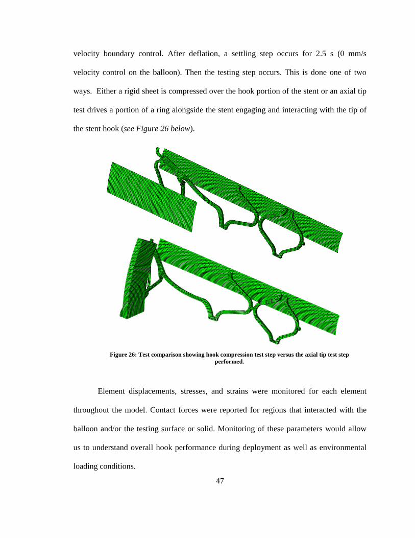
velocity boundary control. After deflation, a settling step occurs for 2.5 s (0 mm/s
velocity control on the balloon). Then the testing step occurs. This is done one of two
ways. Either a rigid sheet is compressed over the hook portion of the stent or an axial tip
test drives a portion of a ring alongside the stent engaging and interacting with the tip of
the stent hook (see Figure 26 below).
Element displacements, stresses, and strains were monitored for each element
throughout the model. Contact forces were reported for regions that interacted with the
balloon and/or the testing surface or solid. Monitoring of these parameters would allow
us to understand overall hook performance during deployment as well as environmental
loading conditions.
Figure 26: Test comparison showing hook compression test step versus the axial tip test step
performed.

48
4. RESULTS
Each hook deploys differently from one another. However, all result in an overall stent
diameter increase during inflation. As the stent diameter increases, the hooks tips displace
into their desired positions. The main goal of these different hook designs was to see the
differences in deployment. In order to compare the different stents, displacements at the
middle of the stents as well as the end of hook tip were recorded.
Figure 27: Generic Stent Model Deployed:
A, Top view after deployment.
B, Side view after deployment.
C, Isometric after deployment.
A B
C

49
A B
C Figure 29: Double Four-Bar Stent Model Deployed:
A, Top view after deployment.
B, Side view after deployment.
C, Isometric after deployment.
A B
C Figure 28: Flexible Hook Tip Stent Model Deployed:
A, Top view after deployment.
B, Side view after deployment.
C, Isometric after deployment.

50
Table 6: Hook Variation Deployment Hook and Mid-Stent Diameters
Hook Variation Mid-Stent Diameter (mm) Hook Tip Diameter (mm)
Generic 7.628 11.697
Flexible Hook Tip 7.628 11.452
Double Four-Bar 7.630 10.662
Figure 31: Hook Variation Overlay
0 1 2 3 4 5 6 7 8 90
1
2
3
4
5
6
Time (s)
Dis
pla
cem
ent
(mm
)
Displacement vs. Time
Generic Hook
Generic Mid-Stent
Flexible Tipped Hook
Flexible Tipped Mid-Stent
Double Four-bar Hook
Double Four-bar Mid-Stent
Figure 30: Displacement Magnitude vs. Time for all hook variations

51
Generic
Flexible Hook Tip
Double Four-Bar
Mid-Stent Hook Tip
Figure 32: Displacement vs. Time at middle of the stent and at the hook for all hook variations during deployment.
0 2 4 6 8
0
1
2
3
Dis
pla
cm
ent
(mm
)
Time (s)
X-Direction Y-Direction Z-Direction Magnitude
0 2 4 6 8
0
2
4
6
0 2 4 6 8
0
1
2
3
0 2 4 6 8
0
2
4
6
0 2 4 6 8
0
1
2
3
0 2 4 6 8
0
2
4
6

52
8 9 10 11 12 133
3.5
4
4.5
5
5.5
Time (s)
Dis
pla
cem
ent
(mm
)
Stent Testing Step: Displacement vs. Time
8 9 10 11 12 133
3.5
4
4.5
5
5.5
8 8.5 9 9.5 10 10.5 11 11.5 12 12.53
3.5
4
4.5
5
5.5
Compression Axial Testing
Generic
Flexible Hook Tip
Double Four-Bar
Figure 33: Displacement vs. Time at hook tip for all hook variations during the compression and axial testing
step of the simulation.

53
A
B
C
Figure 34: Generic Stent Deployed vs. Deformed: A) Fully Deployed Generic Stent; B) Generic Stent under
compressive load; C) Generic Stent hook after axial hook testing

54
Figure 35: Flexible Hook Tip Stent Deployed vs. Deformed: A) Fully Deployed Flexible Hook Tip Stent; B)
Flexible Hook Tip Stent under compressive load; C) Flexible Hook Tip after axial hook testing
C
A
B

55
A
B
C
Figure 36: Double Four-Bar Stent Deployed vs. Deformed: A) Fully Deployed Double Four-Bar Stent; B) Double
Double Four-Bar Stent under compressive load; C) Double Four-Bar hook after axial hook testing

56
Stiffness of the different hook variations was also monitored during the two different
testing steps in the simulations. The resultant forces are reported for the contact surface
that interacts with the testing part (either the compression sheet or the axial tip testing
solid). The values reported are for one hook (1 of 12 contained in the entire stent).
Note: Figures 36, 37, & 38 are Force vs. Displacement profiles for one hook. In each
stent, there are a total of 12 hooks.
0 0.5 1 1.5 2 2.5 30
0.1
0.2
0.3
0.4
0.5
0.6
0.7
Displacment (mm)
Forc
e (
N)
Generic Stent: Force vs. Displacement During Different Steps
Inflation
Compression
Axial Testing
Figure 37: Force vs. Displacement during different steps for the Generic Stent

57
0 0.5 1 1.5 2 2.5 30
0.1
0.2
0.3
0.4
0.5
0.6
0.7
Displacment (mm)
Forc
e (
N)
Flexible Hook Tip Stent: Force vs. Displacement During Different Steps
Inflation
Compression
Axial Testing
Figure 38: Force vs. Displacement during different steps for the Flexible Hook Tip Stent
0 0.5 1 1.5 2 2.5 30
0.5
1
1.5
Displacment (mm)
Forc
e (
N)
Double Four-Bar Stent: Force vs. Displacement During Different Steps
Inflation
Compression
Axial Testing
Figure 39: Force vs. Displacement during different steps for the Double Four-Bar Stent

58
5. DISCUSSION
All of the hook variations have different deployment profiles. While they all have
roughly the same deployed stent body diameter, the hooks of each are very different. The
generic stent has the largest deployment diameter associated with the hook tip at
11.697mm. The flexible tipped and double four-bar stents have smaller radii, 11.452mm
and 10.662mm respectively.
The main basis for comparison is how each of these hooks would respond to the
biliary tissue. One of the possible disadvantages with the generic stent is that there may
not be enough traction distally to prevent a proximal migration. With the generic stent
hook configuration and assuming only the hook tip interacts with the biliary duct system,
there is relatively less contact between the hooks and the biliary lining than the flexible
and double four-bar hook configurations.
While the generic stent may not provide enough traction, the flexible hook tip and
double four-bar stent are designed to deform in such a manner that with cause increased
interaction. In Figure 35 we can see that upon compression the tip of the flexible hook tip
stent bends to contour what would be the biliary lining. As opposed to the generic stent,
the flexible hook tip stent would provide added traction that would ultimately increase
interaction with the lining and reduce the risk of migration. The flexible hook tip stent
would also reduce the risk of perforation due to the blunter loading of the tissue.
Likewise with the flexible hook tip stent, the double four-bar stent would also
increase interaction with the biliary lining, although does so by a very different means.
Upon deployment, it will take a shape that will interact with the lining greater than the
generic stent. From Figure 36 it is visible to see that the stent, when compressed, will

59
have the mid-hook brace run parallel with the biliary duct. This will be coaxial to the
stent body as well as the bile duct. This will ultimately increase the amount of traction
and in turn reduce migration. Relative to the generic stent, the double four-bar hooked
stent would also reduce the risk of perforation due to the blunter loading of the tissue.
Each stent has a location that exceeds the tensile strength. The tensile strength for
annealed stainless steel 316 is 586 MPa [15, 16]. With this material, each of the stents
would fail at different locations. There are multiple remedies for this situation. One
solution is to improve and alter features such that the stresses are less prominent in the
specified stress concentrated areas. The second way to improve this problem would be to
switch the material used. In this case, a cobalt chromium alloy may be a viable solution.
Co-Cr alloys are relatively stiffer and comes with a much higher tensile strength ranging
from 951 – 1220 MPa [15-17]. This material may not only prevent the stent from failing
but also help by adding to the overall stent stiffness.
It is worth noting that these simulations have not incorporated a biliary-duodenal
model. These higher deformation structures may have to be altered as the design process
continues to prevent biliary, duodenal, and/or papillary injury.
6. CONCLUSION
The hooks variations deploy in very different manners. The main objective was to
design hook variations that would interact with the biliary duct in different ways.
Increasing the traction between the stent and ductal system would reduce stent migration.
With these distinct designs, increased stent – biliary interaction would occur and reduce

60
stent migration. This would be a major help and reduction in the frequency at which
medical practitioners would have to perform biliary stent exchanges.
7. ACKNOWLEDGEMENT
Funding for this project was provided by Wake Forest Innovations. Additional help
and support was provided by the Virginia Tech – Wake Forest University Center for
Injury Biomechanics.
61
8. REFERENCES
1. Leung, J., Self-Expandable Stents in the Gastrointestinal Tract, in Self-Expandabl
Stents in the Gastrointestinal Tract, R. Kozarek, T. Baron, and H.-Y. Song,
Editors. 2013, Springer: New York. p. 15-31.
2. Dumonceau, J.M., et al., Biliary stenting: indications, choice of stents and results:
European Society of Gastrointestinal Endoscopy (ESGE) clinical guideline.
Endoscopy, 2012. 44(3): p. 277-98.
3. Dumonceau, J.M., et al., Biliary stents: models and methods for endoscopic
stenting. Endoscopy, 2011. 43(7): p. 617-26.
4. van Boeckel, P.G., F.P. Vleggaar, and P.D. Siersema, Plastic or metal stents for
benign extrahepatic biliary strictures: a systematic review. BMC Gastroenterol,
2009. 9: p. 96.
5. Lammer, J. and K. Neumayer, Biliary drainage endoprostheses: experience with
201 placements. Radiology, 1986. 159(3): p. 625-9.
6. Mueller, P.R., et al., Biliary stent endoprosthesis: analysis of complications in
113 patients. Radiology, 1985. 156(3): p. 637-9.
7. Hontz, R.A., M.D. Tripp, and L.P. Kline, Stents keep occluded vessels open. RN,
1991. 54(3): p. 50-4.
8. Chaurasia, O.P., et al., Endoscopic techniques for retrieval of proximally migrated
biliary stents: the Amsterdam experience. Gastrointest Endosc, 1999. 50(6): p.
780-5.
9. Ahrendt, S.A. and H.A. Pitt, A history of the bilioenteric anastomosis. Arch Surg,
1990. 125(11): p. 1493-500.
62
10. Donelli, G., et al., Plastic biliary stent occlusion: factors involved and possible
preventive approaches. Clin Med Res, 2007. 5(1): p. 53-60.
11. Gouma, D.J., Stent versus surgery. HPB (Oxford), 2007. 9(6): p. 408-13.
12. Bonsignore, C., Open Stent Design, ed. C. Commons. 2011, Fremont, CA: Nitinol
Devices & Components Inc. .
13. Hibbeler, R.C., Mechanics of Materials. 1994, Macmillan: New York.
14. Gervaso, F., et al., On the effects of different strategies in modelling balloon-
expandable stenting by means of finite element method. J Biomech, 2008. 41(6):
p. 1206-12.
15. Brunski, J., ed. Biomaterials Science an Introduction to Materials in Medicine.
ed. B. Ratner, et al. 2004, Elsevier Academic Press: San Diego.
16. Park, J. and Y. Kinm, eds. Metallic Biomaterials. Biomaterials Principles and
Applications, ed. C. Press. 2003: Boca Raton.
17. Davis, J., Metallic Materials, in Handbook of Medical Devices. 2003, ASM
International: Materials Park. p. 21-50.

63
Chapter IV: Parametric Study of a Deployment Hinge using
Finite Element Analysis
Jared Mitchell1, Clifford Howard Jr.
2, Philip J. Brown
1
1Virginia Tech – Wake Forest University Center for Injury Biomechanics,
Winston-Salem, NC
2 Wake Forest Baptist Health Medical Center, Winston-Salem, NC

64
1. ABSTRACT
Parametric studies can often be performed to optimize a design. After performing
initial simulations on full models of novel biliary stents, it was noticed that often times
the stent would fail during deployment due to material failure (surpassing the tensile
strength). This mainly occurs at the side junction of a hinge contained within the stent.
The hinge is necessary in the stent design because of its anti-migration hooks that
displace and deploy further than the main body of the stent. These hinges make it
possible for this precise deformation to occur. To evaluate hinge performance, the width
and length of the hinge’s oval slot, as well as, the side junction thickness were varied. All
hinge configurations were modeled, assigned an elasto-plastic stainless steel 316 material
model, and prescribed the same loading condition using Abaqus. Stresses, strains,
displacements, and overall stiffness were monitored throughout the simulation and
reported.

65
2. INTRODUCTION
A cantilever beam is a beam rigidly fixed at one end with the other unconstrained.
Because of is unique properties and esthetic appeal, cantilevers structures can often be
seen in many buildings. They also, however, can be seen in parts on a much finer scale
(i.e. Microelectromechanical systems [MEMS]). This simplistic configuration provides a
template that is easily understood and is ideal for material analysis. A simple cantilever
allows for monitoring of bending and stiffness, among other variables, to be recorded and
analyzed. All of which can be studied with the use of simulations [1, 2].
Hinges are often placed in beams to reduce the amount of stress seen in a location.
This occurs because of the hinges inability to transmit moments or, in other words, it
eliminates the internal moment seen at the hinge’s location [1, 2]. This can be beneficial
if a beam requires a large deformation, but you do not want to surpass the tensile strength
of the material. Having a hinge in place can, by reducing the internal moment, ultimately
reduce the stresses experienced in a specific part.
A stent is either a metallic or plastic tube that is used to restore patency to a
passageway within the body [3-7]. There are many different types with the most common
being vascular and gastrointestinal stents. In order to implant metallic stents within the
body, it must be deployed by either a balloon expansion or it itself have self-expanding
properties. In both of these scenarios loading of the stent must occur.
A portion of the Wake Forest Innovations non-migrating biliary stent has been
modelled as a cantilever beam which contains a hinge. This portion has been modelled to
better understand the stresses, strains, displacements/angle in the hinge in order to
optimize its design and understand the overall hinge performance.

66
3. METHODS
Hinge Dimensioning and Parameter Variation:
A solid model of the hinge portion from the stent was modeled using Simulia’s
Abaqus/CAE version 6.14. The hinges modeled measure between 0.14 mm to 0.22 mm
with additional length both distally and proximally to allow for appropriate boundary
conditioning. In order to evaluate performance of the hinge, three parameters were
varied. The parameters varied were slot width, slot length, and side joint thickness (seen
highlighted in Figure 39). With two variations for each parameter, there exist a total of
eight possible cases (see Figure 40 for all hinges simulated). In each case the stiffness as
well as the stress contained in the hinge were monitored and reported for comparison.
Figure 40: Base hinge model with study parameters identified.
BLUE: slot width ; RED: slot length ; ORANGE: side joint thickness

67
0.1
0 0.2
25
0.0
3
0.0
6 0.1
9
0.0
5
0.0
6 0.1
9
0.0
3
AA
A
0.0
6 0.2
2
0.0
6 0.2
2
0.0
5
0.1
0 0.2
75
0.0
5
0.1
0
0.2
25
0.0
5
0.1
0 0.2
75
AA
B
AB
A
BB
B
BA
B
BB
A
BA
A
AB
B
0.0
3
0.0
3
Fig
ure
41
: D
imen
sio
ns
of
all
Hin
ge
Co
nd
itio
ns
(NO
TE
: A
ll d
imen
sion
s are
in
mm
an
d a
ll f
igu
res
are
not
to s
cale
)

68
For simplicity and labelling purposes, each hinge was given a three letter identity.
Each letter (“A” or “B”) corresponds to a value associated with a particular dimension.
The first letter denotes the slot width, the second, the slot length and the third and last, the
side joint thickness. For slot width, A indicated a 0.06 mm width while B designates a
0.10 mm dimension. Likewise with side joint thickness, the A dimension measures 0.03
mm and B indicates 0.05 mm. Due to symmetry and constraints of the hinge, the slot
length for the A and B state depend on the slot width. When the slot width is in the A
state, slot length is either 0.19 mm (A) or 0.225 mm (B). If the slot width is in the B state
then the slot length is 0.23 mm (A) or 0.275 mm (B). (The B state dimension for the slot
length is roughly 1.2 times that of the A state.) This identifying was performed such that
data and processing could be easily read and understood (See Table 6 & 7 and Figure 40
for clarification. As an example an “ABA Hinge” would have the following dimensions:
[A] Slot Width = 0.06 mm ; [B] Slot Length = 0.225 mm ; [A] Side Joint Thickness =
0.03 mm).
Table 7: Dimension of Slot Length and Side Joint Thickness when Slot Width is in “A” State (0.06mm)
Slot Width = 0.06 mm “A State” Dimension (mm) “B State” Dimension (mm)
Slot Length 0.19 0.225
Side Thickness 0.03 0.05
Table 8: Dimension of Slot Length and Side Joint Thickness when Slot Width is in “B” State (0.10mm)
Slot Width = 0.10 mm “A State” Dimension (mm) “B State” Dimension (mm)
Slot Length 0.23 0.275
Side Thickness 0.03 0.05

69
The hinge material resembles that of stainless steel 316 [8, 9]. An elasto-plastic material
model was used with the following parameters: Density = 8000 kg/m3 ; Young’s
Modulus = 193 GPa ; Poisson’s Ratio = 0.27 ; Yield Strength = 193 MPa ; See Table 8
and Figure 41 for parameters associated with plastic deformation.
Table 9: Reflects the Abaqus plastic deformation input table
Yield Stress (MPa) Plastic Strain
193 0
193 0.003
316 0.0037
400 0.03
550 0.14
700 0.5
701 1
0 0.1 0.2 0.3 0.4 0.5 0.6 0.7 0.8 0.9 1100
200
300
400
500
600
700
800
Str
ess (
MP
a)
Plastic Strain
SS 316: Stress vs. Plastic Strain
Figure 42: Stent Material Model for Stainless Steel Grade 316: Stress vs. Plastic Strain

70
Simulation Set-Up: Constraints, Meshing, and Boundary Conditions/Loads:
The simulations performed used Abaqus/CAE version 6.14 and were implicit
(Abaqus/Standard) simulations. All of the hinges were meshed using Abaqus’ hexahedral
C3D8R type elements. This element type is an 8-node linear brick with reduced
integration and hourglass control. Partitioning was done such that the each hinges’
associated mesh was symmetric and did not contain any distorted elements.
In order to mimic a cantilever, a fixed boundary condition is applied to the end of
the hinge portion. This will not allow the nodes associated with this face to move (or
rotate) in any direction. Opposite the fixed end, a force is applied in the y-direction to
each node that is on the mid-transverse plane. This is the driving force behind the rotation
of the hinge about the Z-axis. This force was a 0.01 N force applied to each of the 19
nodes for 2 seconds. See Figure 43 for boundary conditions.
A
B
Figure 43: A, Partitioning of the AAA Hinge; B, Mesh associated with the AAA Hinge

71
The loading at the end maintains a force in the Y direction even as the hinge
rotates; this results in some tension to occur in the hinge. While this is what occurs during
actual deployment, an additional test was performed on the AAA hinge to compare a pure
moment about the origin to a force applied to the 19 described nodes. In this pure
moment scenario, a rigid cylinder was given a velocity in the Y direction (See Figure 44A
for setup). This would result in the contact force creating a moment about the origin
rotating the hinge about the Z axis with added tension. This was done by applying a 0.1
mm/s Y - velocity to the all of the nodes of the cylinder for 5 seconds.
Similar to this test, the AAA Hinge was also tested in lateral bending (bending not
in the designed hinge direction). This was done by a similar rigid cylinder movement
(See Figure 44B for setups), but was only simulated for 3 seconds as opposed to 5.
Figure 44: Figure depicting fixed end boundary condition and forces applied to nodes at opposite end

72
For all simulations, hinge stresses, strains, and deformation angle was reported.
From these monitored outputs, the angle at which the stent would failure was also
determined. After analyzing the full stent’s deployment, it was noted that the deployed
angle at the hinge was roughly 55 degrees. Because of this, the stress at 55 degrees was
reported for all hinge designs.
B
A
Figure 45: Additional Test Setups for AAA Hinge. A: Strictly Moment Test Setup ; B: Lateral
Bending Test Setup

73
A
B
C
Figure 46: BBB Hinge.
A: Isometric of BBB Hinge prior to deformation
B: Isometric of deformed BBB Hinge
C: Side View of deformed BBB Hinge
The AAA Hinge has the same dimensions as the hinge used in the full stent.
Comparisons were made between the the two methods of bending, force applied to the
end nodes (with some tension in the hinge) and the rigid cylinder moment creating only a
moment about the origin, to the actual generic stent deployment.
4. RESULTS
All of the hinges performed with primary bending occuring at the hinge (as
opposed to the fixed end).

74
0 20 40 600
0.005
0.01
0.015
0.02
0.025
0.03
0.035
Mom
ent
(N*m
m)
Angle (degrees)
0 20 40 600
0.01
0.02
0.03
0.04
0.05
0.06
0.07
0 20 40 600
0.005
0.01
0.015
0.02
0.025
0.03
0.035
0 20 40 600
0.01
0.02
0.03
0.04
0.05
0.06
0.07
Hinge Failure Angle
‘A State’ Slot Width (0.06 mm)
Side Joint Thickness
0.03 mm [A] 0.05 mm [B]
Slo
t L
ength
0.1
9 m
m [
A]
0.2
25 m
m [
B]
Figure 47: Moment vs. Angle for hinges with slot width in the ‘A’ state.

75
0 20 40 60 800
0.005
0.01
0.015
0.02
0.025
0.03
0.035
Mom
ent
(N*m
m)
Angle (degrees)
0 20 40 600
0.01
0.02
0.03
0.04
0.05
0.06
0.07
0 20 40 60 800
0.005
0.01
0.015
0.02
0.025
0.03
0.035
0 20 40 600
0.01
0.02
0.03
0.04
0.05
0.06
0.07
Hinge Failure Angle
‘B State’ Slot Width (0.10 mm)
Side Joint Thickness
0.03 mm [A] 0.05 mm [B]
Slo
t L
ength
0.2
3 m
m [
A]
0.2
75 m
m [
B]
Figure 48: Moment vs. Angle for hinges with slot width in the ‘B’ state.

76
Figure 49 and Table 10 show the initial stiffness associated with the hinge is
much greater than the stiffness associated with late deformation. In order to quantify the
stiffness of the hinge throughout the bending, linear models have been fit to the Moment
vs. Angle plots. The hinge has been approximated to have two different stiffnesses
corresponding to how the hinge is deforming: an initial stiffness and a post initial loading
stiffness. It, however, is worth noting that the initial stiffness is not the elastic stiffness as
the hinge yields in most instances after a deformation of roughly one degree. The
stiffnesses (slopes) of each portion were recorded for comparison.
0 10 20 30 40 50 600
0.005
0.01
0.015
0.02
0.025
0.03
0.035
Mom
ent
(N*m
m)
Angle (degrees)
AAA Hinge: Moment vs. Angle
Hinge Failure Angle
Figure 49: Linear Stiffness Model for initial and secondary deformation
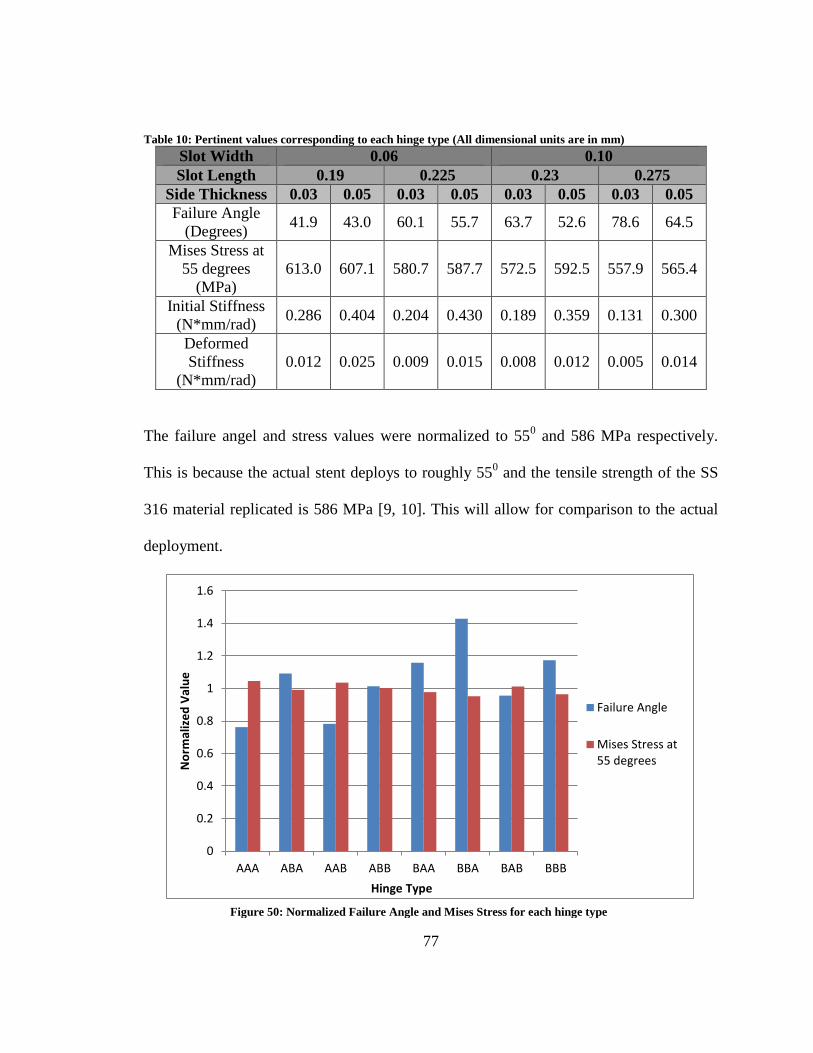
77
Table 10: Pertinent values corresponding to each hinge type (All dimensional units are in mm)
Slot Width 0.06 0.10
Slot Length 0.19 0.225 0.23 0.275
Side Thickness 0.03 0.05 0.03 0.05 0.03 0.05 0.03 0.05
Failure Angle
(Degrees) 41.9 43.0 60.1 55.7 63.7 52.6 78.6 64.5
Mises Stress at
55 degrees
(MPa)
613.0 607.1 580.7 587.7 572.5 592.5 557.9 565.4
Initial Stiffness
(N*mm/rad) 0.286 0.404 0.204 0.430 0.189 0.359 0.131 0.300
Deformed
Stiffness
(N*mm/rad)
0.012 0.025 0.009 0.015 0.008 0.012 0.005 0.014
The failure angel and stress values were normalized to 550 and 586 MPa respectively.
This is because the actual stent deploys to roughly 550 and the tensile strength of the SS
316 material replicated is 586 MPa [9, 10]. This will allow for comparison to the actual
deployment.
0
0.2
0.4
0.6
0.8
1
1.2
1.4
1.6
AAA ABA AAB ABB BAA BBA BAB BBB
No
rmal
ize
d V
alu
e
Hinge Type
Failure Angle
Mises Stress at55 degrees
Figure 50: Normalized Failure Angle and Mises Stress for each hinge type

78
An additional test was performed on the AAA hinge (which possesses the same
dimensions as the hinge used in the generic stent). This was used to validate that the
loading each hinge experienced is justifiable and would correlate appropriately to how
the actual hinge would act during deployment.
0
0.05
0.1
0.15
0.2
0.25
0.3
0.35
0.4
0.45
AAA ABA AAB ABB BAA BBA BAB BBB
Stif
fne
ss (
N*m
m /
rad
)
Hinge Type
Initial Stiffness
DeformedStiffness
Figure 51: Initial and Secondary Stiffness for each hinge type
A B
Figure 52: A, deformation cause by force at nodes. B, deformation cause by rigid
cylinder boundary conditioning

79
A
B
Figure 53: Simulation performed on AAA Hinge to analyze lateral bending
0 10 20 30 40 50 600
100
200
300
400
500
600
700
Str
ess (
MP
a)
Angle (degrees)
Generic Stent Hinge Angle vs. Time
AAA Hinge w/ Nodal Force
AAA w/ Cylinder Boundary Conditioning
Generic Stent Hinge
AAA Hinge in Lateral Bending
Figure 54: Mises Stress vs. Angle for Different Loading Mechanisms for the AAA Hinge

80
5. DISCUSSION
All of the hinges have different deflections associated with their bending. All,
however, have bending occurring at the hinge. A true cantilever beam under similar
loading conditions would result in bending occurring throughout the beam. In each
simulation, a vast majority of the bending occurs at the hinge location.
While each hinge allows for bending in the appropriate plane, the manner in
which their deformation occurs depends mainly on their parameter dimension. Variations
in the parameters ultimately cause resulting changes in the overall stiffness of the hinge.
Take the side joint thickness for example. In every case, an increased thickness (the B
A B
C
Figure 55: Deformation at 55 degrees: A: Hinge with nodal force applied; B: Hinge with rigid
cylinder moment application; C: Generic Stent with balloon expansion.

81
state versus the A state) is associated with increased rigidity. This allows us to conclude
that side thickness plays an important role in the stiffness attributed to the overall hinge.
Each hinge was attributed two linear approximated stiffnesses (Table 10 & Figure 49).
The initial stiffness, however, is not associated with the elastic deformation of the hinge
but extended into plastic deformation. Each hinge tends to eclipse their yield stress after
roughly one degree of rotation.
In addition to stiffnesses, stresses and failure angle were monitored. One of the
values recorded was the stress that occurs at 55o of rotation. 55
o was used because, after
evaluating the full stent, the hinge contained in the hook portion deforms to rough 55o
when fully deployed. This value reported indicated whether or not the hinge would fail
upon deployment under the full stents loading conditions. Likewise with failure angle,
this provides a benchmark for determining the maximum amount of rotation that can
occur prior to reaching the tensile strength. Figure 50 is a plot that can be used for
determining failure of the hinge. In this figure the failure angle and stress at 55o
are
normalized to 55o and 586 MPa respectively. This is because, as previously stated, the
deployed angle is 55o
and the tensile strength of annealed stainless steel 316 (the material
model used) is 586 MPa [9, 10]. When evaluating a hinge types (Figure 50), normalized
failure angle value above 1 (and/or a stress at 55o below 1) indicated that the hinge would
not fail if deployed in the full stent.
This study was designed to evaluate hinge dimensions and there effect of
performance. Just because one hinge fails does not mean that those dimensions will not
be used. Because these hinges are implemented within non-migrating stents stiffness is a
major factor. Increased stiffness has been shown to reduce migration [11]. In order to
82
maintain its position in the biliary duct, a hinge may require a certain stiffness. With
certain hinges while the material may not fail, the stent as a whole may fail and migrate
from its desired position. An additional alteration can be made in order to maintain
stiffness and possibly expunge material failure: change the material to a cobalt chromium
alloy. Co-Cr, although less common than stainless steel, is a relatively stiffer material and
also brings with it a higher tensile strength ranging from 951 – 1220 MPa [8]. This may
not only prevent material failure but also could help provide added stiffness which may
have an added benefit in helping with stent migration.
6. CONCLUSION
All of the hinges performed differently and some, given the prescribed loading
conditions, fail. Just because they fail, however, does not mean that the parameters
associated with the hinge are unusable. It is quite the contrary. Each hinge has its
advantages and disadvantages as does each stent. In general, a stent has different
dimensions associate with not only the application but also the person. This study
provides us with a broad spectrum of hinge designs such that we can select the
appropriate hinge or the appropriate dimensions to start from for the specific application
being targeted.
83
7. ACKNOWLEDGEMENT
Funding for this project was provided by Wake Forest Innovations. Additional help
and support was provided by the Virginia Tech – Wake Forest University Center for
Injury Biomechanics.

84
8. REFERENCES
1. Beer, F., et al., eds. Mechanics of Materials. Sixth ed. 2012, McGraw-Hill.
2. Hibbeler, R.C., ed. Structural Analysis. Eighth ed. 2012, Pearson Presntice Hall:
Upper Saddle River.
3. Dumonceau, J.M., et al., Biliary stenting: indications, choice of stents and results:
European Society of Gastrointestinal Endoscopy (ESGE) clinical guideline.
Endoscopy, 2012. 44(3): p. 277-98.
4. Leung, J., Self-Expandable Stents in the Gastrointestinal Tract, in Self-Expandabl
Stents in the Gastrointestinal Tract, R. Kozarek, T. Baron, and H.-Y. Song, Editors.
2013, Springer: New York. p. 15-31.
5. Hontz, R.A., M.D. Tripp, and L.P. Kline, Stents keep occluded vessels open. RN,
1991. 54(3): p. 50-4.
6. Mueller, P.R., et al., Biliary stent endoprosthesis: analysis of complications in 113
patients. Radiology, 1985. 156(3): p. 637-9.
7. Burcharth, F., A new endoprosthesis for nonoperative intubation of the biliary
tract in malignant obstructive jaundice. Surg Gynecol Obstet, 1978. 146(1): p. 76-
8.
8. Davis, J., Metallic Materials, in Handbook of Medical Devices. 2003, ASM
International: Materials Park. p. 21-50.
9. Park, J. and Y. Kinm, eds. Metallic Biomaterials. Biomaterials Principles and
Applications, ed. C. Press. 2003: Boca Raton.

85
10. Brunski, J., ed. Biomaterials Science an Introduction to Materials in Medicine. ed.
B. Ratner, et al. 2004, Elsevier Academic Press: San Diego.
11. Isayama, H., et al., Measurement of radial and axial forces of biliary self-
expandable metallic stents. Gastrointest Endosc, 2009. 70(1): p. 37-44.

86
Chapter V: Summary of Research
The thesis presents research performed to alter the current concept of biliary
stents and reduce dysfunction due to migration. Through the implementation of additional
hook structures added to the overall stent, the following objectives were analyzed and
completed:
1. Finite element analysis of the stents deployment to monitor hook
displacement.
2. Compare different hook variations to see how versions might deploy
differently as well as interact with the surrounding tissue differently.
3. Compare different hook hinge designs in order to prevent failure as well as
understand dimensions to optimize hook stiffness.
This research will help limit dysfunction due to migration that occurs not only in
biliary stents but also in other areas as well. Because this design concept can cross over to
other stent applications this idea can help reduce migration in other locations within the
body. The stents designed and developed in this thesis (at the time of writing) do not have
intellectual property protection. Because of this, publication of this research will be held
until appropriate patents have been accepted and completed. In the future research from
Chapters II and III may be submitted for publication in the Journal of Medical Devices.

87
Scholastic Vita
Jared D. Mitchell Graduate Student & Research Engineer Virginia Tech – Wake Forest University Center for Injury Biomechanics 575 N. Patterson Ave, Suite 120 Winston-Salem, NC 27101
Mobile: (516) 780-2606
Work: (336) 713-1263 [email protected]
EDUCATION Virginia Tech – Wake Forest University, Winston-Salem, NC May 2016 School of Biomedical Engineering & Sciences Master of Science, Biomedical Engineering Advisor: Dr. Philip J. Brown Washington and Lee University, Lexington, VA May 2014 Bachelor of Science in Physics-Engineering Advisor: Dr. Joel Kuehner EXPERIENCE VT – WFU Center for Injury Biomechanics 2014-Present Graduate Student & Researcher Analyze head impact exposure in the sport of lacrosse and how it relates to Traumatic
Brain Injury Monitor head accelerations using i1 Biometrics Vector mouthguards which are
equipped with an accelerometer and a gyroscope Wake Forest Innovations 2014-Present Medical Device Research Engineer Work alongside doctors, nurses, and physicians to develop innovative medical devices Design biomedical devices for production using SolidWorks 2015 Perform necessary Finite Element Analysis simulations using Abaqus CAE 6.14 Washington and Lee University Physics & Engineering Department 2012-2014 R.E. Lee Scholar: Research Assistant to Professor Joel Kuehner Improving Heat Transfer for a Heated Horizontal Cylinder Performed PIV (Particle Image Velocimetry) measurements of water flow around a
heated horizontal cylinder using LaVision’s DaVis Investigated flow in the boundary layer as it relates to heat transfer SKILLS
Abaqus Adobe Photoshop AutoCAD Autodesk Inventor Kinovea Labview Matlab Microsoft Office SolidWorks

88
PROFESSIONAL CERTIFICATIONS & WORKSHOPS Abaqus/CAE: Import Geometry and Meshing (April 2015) Abaqus/CAE: Introduction to Abaqus/CAE (June 2015) LS-DYNA: Introduction to LS-DYNA (September 2015)
PUBLICATIONS
1. Kuehner J, Hamed A, Mitchell J, “Experimental Investigation of the Free Convection Velocity Boundary Layer and Plume Formation Region for a Heated Horizontal Cylinder”, 10/22/2014, International Journal of Heat and Mass Transfer (journal article)
2. Mitchell J, Brown P, Olympio M. “Design Behind Improving Efficiency in Endotracheal Tube Changes”, Tampa, FL, Biomedical Engineering Society Annual Meeting, October 2015 (poster)
3. Brown P, Gillispie G, Mitchell J, West J, Stitzel J, Hsu W. “Biomechanical Analysis of Coaxial and Cortical Trajectory Pedicle Screws in Lumbar Spine Fusion Constructs”, Tampa, FL, Biomedical Engineering Society Annual Meeting, October 2015 (poster)
4. Brown P, Gillispie G, Mitchell J, West J, Stitzel J, Hsu W. “Hybrid Fusion Technique of Standard Pedicle and Cortical Bone Screws in Lumbar Spine Fusion” Orlando, FL, Orthopedic Research Society Annual Meeting, March 2016 (poster)