Embed Size (px)
Citation preview
Finite Element Analysis of a Novel Design of aThree Phase Transverse Flux Machine with an External Rotor
Erich Schmidt, Member, IEEEInstitute of Electrical Drives and Machines, Vienna University of Technology, Vienna, Austria
Abstract – The permanent magnet excited trans-verse flux machine is well suited in particular for directdrive applications of electric road vehicles. The 3D fi-nite element model with completely independent rotorand stator parts includes only two poles of the machinewith appropriate repeating periodic boundary condi-tions for the unknown degrees of freedom of the 3Dmagnetic vector potential. Consequently, the variousangular rotor positions can be calculated by utilizingthe sliding surface approach and a domain decomposi-tion algorithm.
I. Introduction
As shown in Fig. 1, the novel design with an externalrotor consists of a three phase arrangement with a totalnumber of 120 poles. The rotor parts of the three phasesare arranged in line and carry the permanent magnetswith an alternating magnetization in circumferential di-rection. On the other hand, the stator parts of the threephases carry the ring windings of the three phases andhave an appropriate mechanical angular shift necessaryfor the three phase operation.
Fig. 1: Three phase transverse flux machine with inline rotor seg-ments and inserted permanent magnets as well as shiftedstator segments and ring windings, finite element modelof two poles
II. Sample Analysis Results
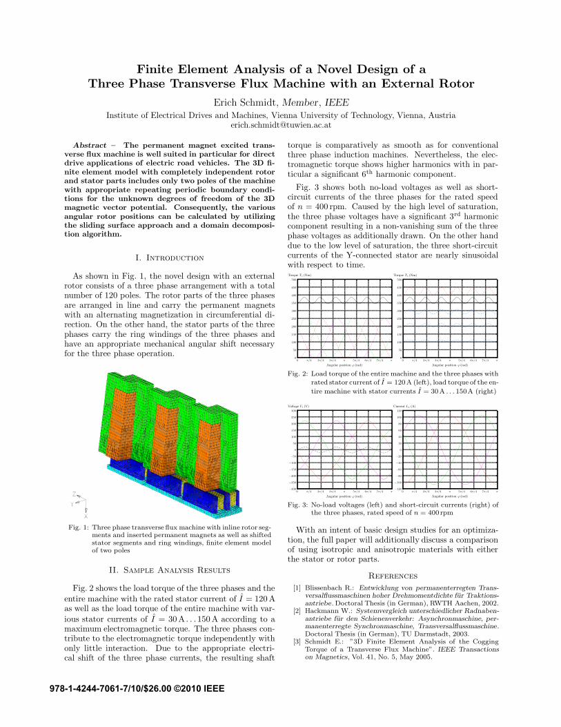
Fig. 2 shows the load torque of the three phases and theentire machine with the rated stator current of I = 120 Aas well as the load torque of the entire machine with var-ious stator currents of I = 30 A . . .150 A according to amaximum electromagnetic torque. The three phases con-tribute to the electromagnetic torque independently withonly little interaction. Due to the appropriate electri-cal shift of the three phase currents, the resulting shaft
torque is comparatively as smooth as for conventionalthree phase induction machines. Nevertheless, the elec-tromagnetic torque shows higher harmonics with in par-ticular a significant 6th harmonic component.
Fig. 3 shows both no-load voltages as well as short-circuit currents of the three phases for the rated speedof n = 400 rpm. Caused by the high level of saturation,the three phase voltages have a significant 3rd harmoniccomponent resulting in a non-vanishing sum of the threephase voltages as additionally drawn. On the other handdue to the low level of saturation, the three short-circuitcurrents of the Y-connected stator are nearly sinusoidalwith respect to time.
0 π/4 2π/4 3π/4 π 5π/4 6π/4 7π/4 π
Angular position ϕ (rad)
0
50
100
150
200
250
300
350
400
450
500
Torque Tz (Nm)
........................................................................................................................................................................
............................................................................................................................................................
............................................................................................................................................................
............................................................................................................................................................
............................................................................................................................................................
................................................................................................................................................
................................................................................................................................................................................................................................................................................................................................................................................................................................................................... ...........
.................................................................................................................................................................................................................
............................................................................................................................................................................................................................
........................................................................................
..........................................................................................................................................................................................................................................................................................................................................................................................................................................................................................................................................................................................................................................................................................................
.........................................................................................................................
...................................................................................................................................................................................................................................................................................................................................................................................................................................................................................................................................................................................................................................................
................................................................................................................................................................................................................. .......................................................
0 π/4 2π/4 3π/4 π 5π/4 6π/4 7π/4 π
Angular position ϕ (rad)
0
50
100
150
200
250
300
350
400
450
500
Torque Tz (Nm)
........................................................................................................................................................................
............................................................................................................................................................
............................................................................................................................................................
............................................................................................................................................................
............................................................................................................................................................
................................................................................................................................................
................................. ................................. ..........................
...........................................................................
...........................................................................
.............................................................................
...................... ................................. ............................................ ................................. ......
......................
.........................................................................
...............
....................................................... ......................
.............................................................................
...........................................................................
..............
...................................................... ......................
............................................................
.................................
........... .............................................................................
........................................................................................
....................................................... ......................
.............................................................................
................................. ........................................................
.................................................................................
...................................................................................................................
.........................................................................................................
............................................
.............................................................................................................................................................................
..........................................
.....................................................................................................................................................................
Fig. 2: Load torque of the entire machine and the three phases with
rated stator current of I = 120 A (left), load torque of the en-
tire machine with stator currents I = 30 A . . . 150A (right)
0 π/4 2π/4 3π/4 π 5π/4 6π/4 7π/4 π
Angular position ϕ (rad)
−300
−250
−200
−150
−100
−50
0
50
100
150
200
250
300
Voltage Ui (V)
......................
..................................................................................................................
......................
.......................
.................................................................................................................
.......................
........................
.........................................................................................................................
........................................................................................................................................................................................................................................................................................................................
.................................................................................................................................................................................................................................................................................................................................................................................................................................................................................................................................................................................................................................................................................................................................................................................................................................................
...........................................................................
.................................................................................................................................................................................................................................................................................................................................................................................................................................................................................................................................................................................................................................................................................................................................................................................................................................................................................................................................................................................................................................................................................
..............................................................................................................................................................................................................................................................................................................................................................................................................................................................................................................................................................................................................................................................................................................................................................................................................................................................................................................................................................................................................................................................................................
..............................................................
0 π/4 2π/4 3π/4 π 5π/4 6π/4 7π/4 π
Angular position ϕ (rad)
−120
−100
−80
−60
−40
−20
0
20
40
60
80
100
120
Current Isc (A)
.............................................................................................................................................................................................................................................................................................................................................................................................................................................................................................................................................................................................................................
...................................................................................................................................................................................................................................................................................................................................................................................................................................................................................................................................................................................................................................................................................
.......................................................................................................................................................................................................................................................................................................................................................................................................................................................................................................................................................................................................................................................................................................................................................................................................................................................................................................................................................................................................................................................................................................................
.........................................................................................................................................................................................................................................................................................................................................................
..................................................................................................................................................................................................................................................................................................................................................................................................................................................................................................................................................................................................................................................................................................................
..............................................................................................................................................................................................................................................................................................................................................................................................................................
Fig. 3: No-load voltages (left) and short-circuit currents (right) ofthe three phases, rated speed of n = 400 rpm
With an intent of basic design studies for an optimiza-tion, the full paper will additionally discuss a comparisonof using isotropic and anisotropic materials with eitherthe stator or rotor parts.
References
[1] Blissenbach R.: Entwicklung von permanenterregten Trans-versalflussmaschinen hoher Drehmomentdichte fur Traktions-antriebe. Doctoral Thesis (in German), RWTH Aachen, 2002.
[2] Hackmann W.: Systemvergleich unterschiedlicher Radnaben-antriebe fur den Schienenverkehr: Asynchronmaschine, per-manenterregte Synchronmaschine, Transversalflussmaschine.Doctoral Thesis (in German), TU Darmstadt, 2003.
[3] Schmidt E.: ”3D Finite Element Analysis of the CoggingTorque of a Transverse Flux Machine”. IEEE Transactionson Magnetics, Vol. 41, No. 5, May 2005.
978-1-4244-7061-7/10/$26.00 ©2010 IEEE