Embed Size (px)
Citation preview
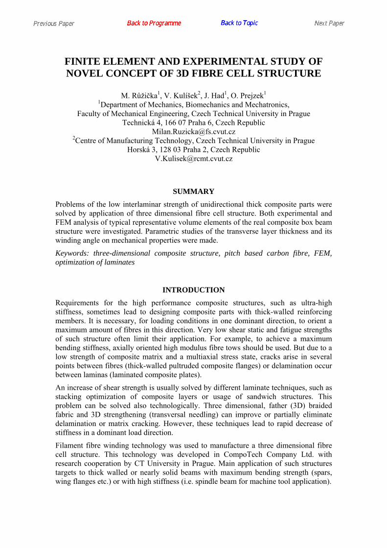
FINITE ELEMENT AND EXPERIMENTAL STUDY OF NOVEL CONCEPT OF 3D FIBRE CELL STRUCTURE
M. Růžička1, V. Kulíšek2, J. Had1, O. Prejzek1
1Department of Mechanics, Biomechanics and Mechatronics, Faculty of Mechanical Engineering, Czech Technical University in Prague
Technická 4, 166 07 Praha 6, Czech Republic [email protected]
2Centre of Manufacturing Technology, Czech Technical University in Prague Horská 3, 128 03 Praha 2, Czech Republic
SUMMARY Problems of the low interlaminar strength of unidirectional thick composite parts were solved by application of three dimensional fibre cell structure. Both experimental and FEM analysis of typical representative volume elements of the real composite box beam structure were investigated. Parametric studies of the transverse layer thickness and its winding angle on mechanical properties were made.
Keywords: three-dimensional composite structure, pitch based carbon fibre, FEM, optimization of laminates
INTRODUCTION Requirements for the high performance composite structures, such as ultra-high stiffness, sometimes lead to designing composite parts with thick-walled reinforcing members. It is necessary, for loading conditions in one dominant direction, to orient a maximum amount of fibres in this direction. Very low shear static and fatigue strengths of such structure often limit their application. For example, to achieve a maximum bending stiffness, axially oriented high modulus fibre tows should be used. But due to a low strength of composite matrix and a multiaxial stress state, cracks arise in several points between fibres (thick-walled pultruded composite flanges) or delamination occur between laminas (laminated composite plates).
An increase of shear strength is usually solved by different laminate techniques, such as stacking optimization of composite layers or usage of sandwich structures. This problem can be solved also technologically. Three dimensional, father (3D) braided fabric and 3D strengthening (transversal needling) can improve or partially eliminate delamination or matrix cracking. However, these techniques lead to rapid decrease of stiffness in a dominant load direction.
Filament fibre winding technology was used to manufacture a three dimensional fibre cell structure. This technology was developed in CompoTech Company Ltd. with research cooperation by CT University in Prague. Main application of such structures targets to thick walled or nearly solid beams with maximum bending strength (spars, wing flanges etc.) or with high stiffness (i.e. spindle beam for machine tool application).
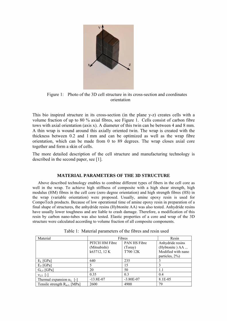
Figure 1: Photo of the 3D cell structure in its cross-section and coordinates orientation
This bio inspired structure in its cross-section (in the plane y-z) creates cells with a volume fraction of up to 80 % axial fibres, see Figure 1. Cells consist of carbon fibre tows with axial orientation (axis x). A diameter of this twin can be between 4 and 8 mm. A thin wrap is wound around this axially oriented twin. The wrap is created with the thickness between 0.2 and 1 mm and can be optimized as well as the wrap fibre orientation, which can be made from 0 to 89 degrees. The wrap closes axial core together and form a skin of cells.
The more detailed description of the cell structure and manufacturing technology is described in the second paper, see [1].
MATERIAL PARAMETERS OF THE 3D STRUCTURE Above described technology enables to combine different types of fibers in the cell core as
well in the wrap. To achieve high stiffness of composite with a high shear strength, high modulus (HM) fibres in the cell core (zero degree orientation) and high strength fibres (HS) in the wrap (variable orientation) were proposed. Usually, amine epoxy resin is used for CompoTech products. Because of low operational time of amine epoxy resin in preparation of a final shape of structures, the anhydride resins (Hybtonite AA) was also tested. Anhydride resins have usually lower toughness and are liable to crash damage. Therefore, a modification of this resin by carbon nano-tubes was also tested. Elastic properties of a core and wrap of the 3D structure were calculated according to volume fraction of all composite components.
Table 1: Material parameters of the fibres and resin used Material Fibres Resin PITCH HM Fibre
(Mitsubishi) k63712, 12 K
PAN HS Fibre (Toray) T700 12K
Anhydride resins (Hybtonite ) AA ... Modified with nano particles, 2%)
EL [GPa] 640 235 3 ET [GPa] 5 15 3 GLT [GPa] 20 50 1.1 νLT [-] 0.35 0.3 0.4 Thermal expansion αL [-] -13.8E-07 -3.80E-07 8.1E-05 Tensile strength Rm L [MPa] 2600 4900 79
zx
y
Material parameters given by manufacturer of fibres and resin were used. Ordinary relative volume of fibre in 3D cell structure is about 60...70 %. Table 1 summarizes material parameters, and final composite modules, which were utilized in numerical simulations.
EFFECTIVE PROPERTIES OF THE CELL STRUCTURE
To simplify calculation of the large, and shape or materially complicated construction, effective elastic modules are needed. There are different approaches to calculation in designing of individual structure parts. To estimate effective module of core and wrap of 3D structure, the classical mixing rule was used. There are different approaches, how the effective properties can be calculated [2]. In [3], use of methods, based on the Eshelby’s tensor was discussed and it was found out, that these methods are not well applicable in this case of high amount of fibres with highly anisotropic properties.
For more accurate computation of elastic modules, FE analysis is required. In following sections, the FE analysis is performed and its results are compared with Voigt and Reuss boundaries. These boundaries can be expressed as Voigt, resp. Reuss models for composite components A and B:
BBAAeff EcEc=E +VOIGT (1)
BBAAeffREUS /Ec/Ec=E1 + (2)
These models expect extreme (series or parallel) topology of the microstructure. As the real microstructure lies between these two extreme layouts, also its modules must lay between the boundaries.
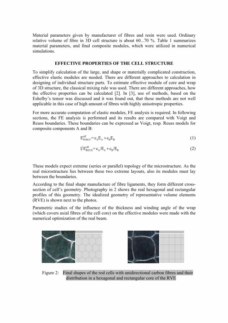
According to the final shape manufacture of fibre ligaments, they form different cross-section of cell’s geometry. Photography in 2 shows the real hexagonal and rectangular profiles of this geometry. The idealized geometry of representative volume elements (RVE) is shown next to the photos.
Parametric studies of the influence of the thickness and winding angle of the wrap (which covers axial fibres of the cell core) on the effective modules were made with the numerical optimization of the real beam.
Figure 2: Final shapes of the rod cells with unidirectional carbon fibres and their distribution in a hexagonal and rectangular core of the RVE
FEM ANALYSIS OF RVE
An analogical approach of a volume homogenisation was selected to calculate effective elastic properties of the 3D cell structure. The real composite structure can be than modelled as anisotropic material, with elastic properties of representative volume element (RVE) [4].
To compare a cell size effect, different numbers of cells in RVE were numerically tested. FE models of RVE than contains 3x3, 4x4 or 5x5 of 3D fibre cells. As mentioned above. Three typical (idealized) basic shapes of fibre cores were modelled - the first one with a hexagonal, the second with square and the third with rectangular profiles.
All FE-models and calculations were made using software ABAQUS. FE-model of the RVE cores and wrap, were modeled with 3D linear brick (incompatible type, C3D8I). Material properties were assumed as shown in Table 1. Cores were made from ultra-high modulus C/E composite, zero degree of fibre direction. Wraps were modeled with high strength C/E composite of the volume ratio of fibres equal to 61%. For parametrical study of elastic properties of RVE different winding angles of the wrap were calculated (in 5 degrees increments) and different relative thickness of the wrap (between 0 and 30 % of cell cross-section). For an application described below, the longitudinal core occupies about 82% of the whole cross-section of the cell and the wrap winding angle is 88.5 degrees, respective ±45 degrees.
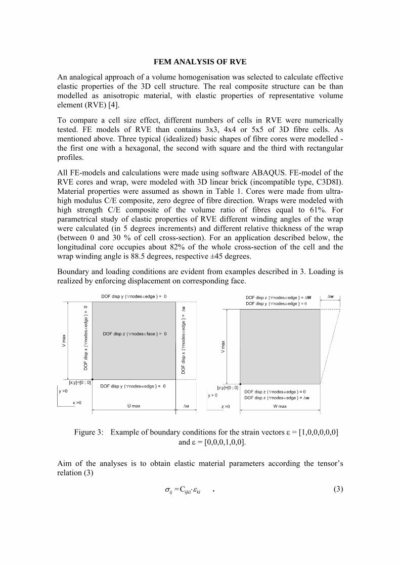
Boundary and loading conditions are evident from examples described in 3. Loading is realized by enforcing displacement on corresponding face.
Figure 3: Example of boundary conditions for the strain vectors ε = [1,0,0,0,0,0] and ε = [0,0,0,1,0,0].
Aim of the analyses is to obtain elastic material parameters according the tensor’s relation (3)
klij εσ ⋅ijklC= . (3)
As described above, elastic constants can be solved by 6 analyses with changing strain vector
ε11=1 ⇒ ε = [1,0,0,0,0,0] ε22=1 ⇒ ε = [0,1,0,0,0,0] ε33=1 ⇒ ε = [0,0,1,0,0,0] ε23=1 ⇒ ε = [0,0,0,1,0,0] ε31=1 ⇒ ε = [0,0,0,0,1,0] ε12=1 ⇒ ε = [0,0,0,0,0,1] .
For example, in an analysis with strain vector ε = [1,0,0,0,0,0]T , solving of equation (3), gives the appropriate stress vector [σ11 σ22 σ33 σ23 σ31 σ12]T , which is directly equal to the first column of the stiffness matrix [C1111 C2211 C3311 C2311 C3111 C1211]T or, for simplicity, [C11 C21 C31 C41 C51 C61]T .
The stress vector, representing a stress response of RVE, is obtained by a procedure based on averaging of element stresses over the whole volume of FE model of RVE. Expression of this can be seen in following relation
∑
∑
=
=
⋅
n
k
k
n
k
kkij
ij
V
V
1
1=σ
σ , (4)
where the terms mean: n - total number of finite elements k - k-th element V k - volume of k-th element
∑=
n
k
kV1
- volume of the whole RVE
Expression of quasi-orthotropic behaviour of 3D structures
After inversion (3), the matrix of elastic constants can be expressed using quasi-orthotropic engineering data, hence
⎥⎥⎥⎥⎥⎥⎥⎥
⎦
⎤
⎢⎢⎢⎢⎢⎢⎢⎢
⎣
⎡
⋅
⎥⎥⎥⎥⎥⎥⎥⎥⎥⎥⎥⎥⎥⎥⎥⎥
⎦
⎤
⎢⎢⎢⎢⎢⎢⎢⎢⎢⎢⎢⎢⎢⎢⎢⎢
⎣
⎡
−−
−−
−−
=
⎥⎥⎥⎥⎥⎥⎥⎥
⎦
⎤
⎢⎢⎢⎢⎢⎢⎢⎢
⎣
⎡
xy
xz
yz
zz
yy
xx
xy
xz
yz
yy
yz
x
xz
z
zy
yx
xy
z
zx
x
yx
x
xy
xz
yz
zz
yy
xx
G
G
G
EEE
EEE
EEE
σσσσσσ
νν
νν
νν
εεεεεε
21
21
21
1
1
1
(5)
Results of the FE analysis were compared with the Voigt and Reuss boundaries on effective properties. Following figures show the FE-results in comparison with the Voigt-Reuss boundaries.
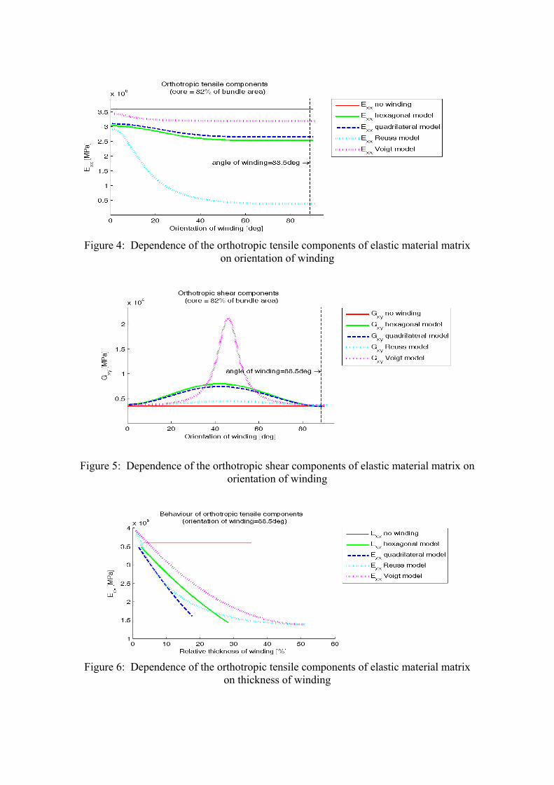
Figure 4: Dependence of the orthotropic tensile components of elastic material matrix
on orientation of winding
Figure 5: Dependence of the orthotropic shear components of elastic material matrix on orientation of winding
Figure 6: Dependence of the orthotropic tensile components of elastic material matrix
on thickness of winding

Figure 7: Dependence of the orthotropic shear components of elastic material matrix on
thickness of winding
From Figures 4 to Figure 7, correspondence between boundaries on effective properties and results of the FE RVE analysis can be seen. These results also show the area of the lay-out to obtain highest improvement of the shear modulus Gxy, close to 45°.
EXPERIMENTAL INVESTIGATIONS AND COMPARISON OF RESULTS
Elastic modules and strength of 3D cell structures were investigated. Three types push and pull tests were performed on rectangular cross-section specimen dimensions b×h×l = 20×30×30 mm. Strains in longitudinal and transversal direction were measured using strain gauges. The terms of stiffness matrix Cij and corresponding terms of engineering material constants in coordinates x, y, z were evaluated from these measurements. Further, tree-point bending tests (distance of supports equal to 200 mm) on the identical rectangular cross-section specimens were realized. Simultaneously, strain gauge data of the shear strains in the ±45° directions were recorded. Transversal shear stiffness was then calculated from the part of deflection which is caused due to the shearing force and the results were compared with strain gauge data evaluation. Measured and evaluated data were then compared with numerical simulations on the RVE.
Table 2. Comparison of the calculated a measured 3D cell parameters (wrap winding angle 88.5 degrees)
Engineering constant FEM Experiments E_xx [GPa] 257.5 308.6 E_yy [GPa] 21.7 30.4 E_zz [GPa] 21.7 38.1 G_yz [GPa] 1.83 x G_zx [GPa] 3.41 x G_xy [GPa] 3.41 3.11
ν_zy 0.086 0.081 ν_xz 0.114 xν_xy 0.114 0.302
FE ANALYSIS OF A COMPLEX 3D CELL STRUCTURE
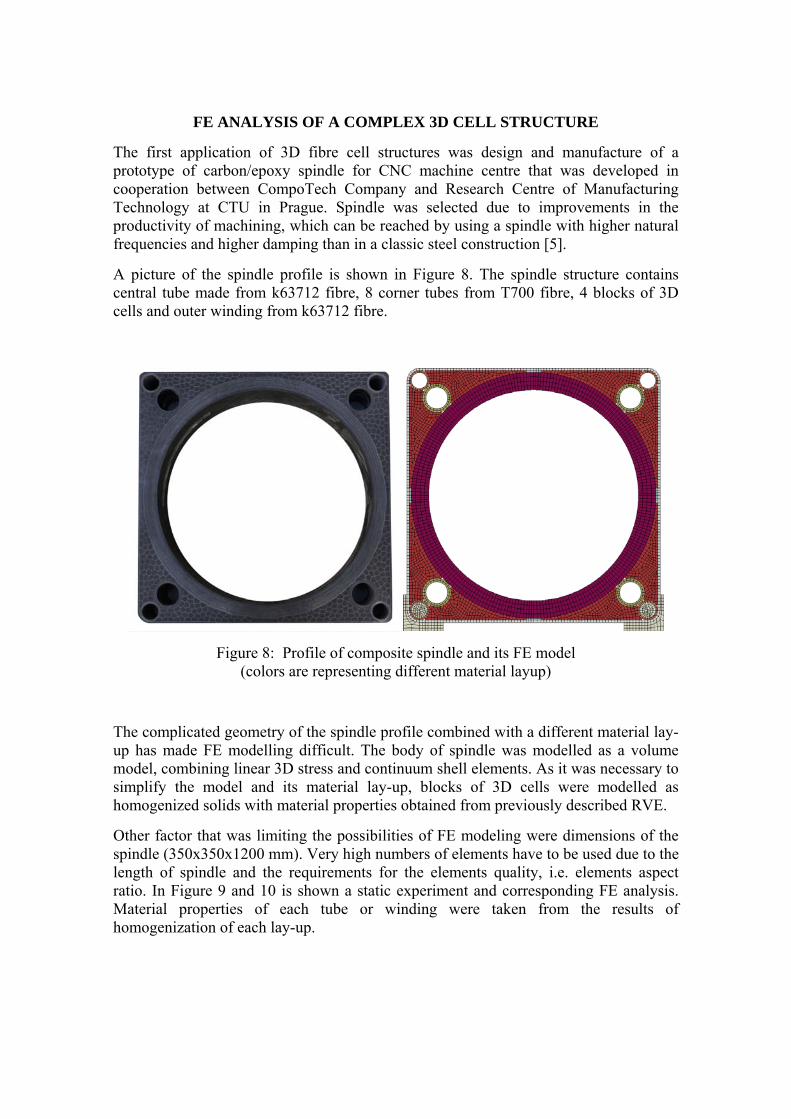
The first application of 3D fibre cell structures was design and manufacture of a prototype of carbon/epoxy spindle for CNC machine centre that was developed in cooperation between CompoTech Company and Research Centre of Manufacturing Technology at CTU in Prague. Spindle was selected due to improvements in the productivity of machining, which can be reached by using a spindle with higher natural frequencies and higher damping than in a classic steel construction [5].
A picture of the spindle profile is shown in Figure 8. The spindle structure contains central tube made from k63712 fibre, 8 corner tubes from T700 fibre, 4 blocks of 3D cells and outer winding from k63712 fibre.
Figure 8: Profile of composite spindle and its FE model (colors are representing different material layup)
The complicated geometry of the spindle profile combined with a different material lay-up has made FE modelling difficult. The body of spindle was modelled as a volume model, combining linear 3D stress and continuum shell elements. As it was necessary to simplify the model and its material lay-up, blocks of 3D cells were modelled as homogenized solids with material properties obtained from previously described RVE.
Other factor that was limiting the possibilities of FE modeling were dimensions of the spindle (350x350x1200 mm). Very high numbers of elements have to be used due to the length of spindle and the requirements for the elements quality, i.e. elements aspect ratio. In Figure 9 and 10 is shown a static experiment and corresponding FE analysis. Material properties of each tube or winding were taken from the results of homogenization of each lay-up.

Figure 9: Measurements of the spindle static stiffness
Figure 10: FE analysis of static stiffness
At the current state of project, a good agreement between results from experiments and FE analysis hasn’t been achieved. FE model has significantly higher stiffness than real body. The measured deflection at the end of composite body was 62 μm while the predicted deflection from FE analysis was 18 μm for the same force. Same conclusions can be made for the modal analysis, where the first three computed frequencies are about 30 % higher than captured frequencies from experiment. The problem of making more accurate FE models of complex structures containing 3D cells will be the goal in the future.

CONCLUSIONS Experimental investigation, as well as numerical simulations, showed that 3D cell composite structure can be more effective in transferring a shearing force than a classical unidirectional or layered structure. Wrap angle of axially oriented fibre in cells about ±45° is needed. Hybrid combination of HM and HS carbon fibres leads to optimal stiffness and strength. With using of hybrid composites, parts of high stiffness and very good shear and normal strength can be designed. It was demonstrated on the prototype of the carbon/epoxy spindle for CNC machine centre.
ACKNOWLEDGEMENTS This work was supported by the Grant Agency of the Czech Republic number 101/08/0299 and 101/08/H068. This work was also supported by Ministry of Education, Youth and Sports of Czech Republic by grant No. 1M0507.
References [1] Uher, O. – Smolík, J. And Růžička, M.: Novel concept of three-dimensional thick
composite structure made from pitch based carbon fibre for machine tool applications. Proceeding of the 17th International Conference on Composite Materials. 27-31 July 2009, Edinburgh, UK.
[2] Steven, G.: Homogenization and inverse homogenization for 3D composite of complex architecture. Engineering Computations: International Journal for Computer-Aided Engineering and Software, V. 34, N.4, 2006.
[3] Prejzek, O.: Analysis and Optimal Design of a Part with 3D-Cell Fibre Composite Structure. Workshop of Applied Mechanics. CTU in Prague, February, 2009.
[4] Barbero, E. J: Finite Element Analysis of Composite Materials. CRC Press, 2008.
[5] Smolík, J.: Nosné díly obráběcích strojů z nekonvenčních materiálů. PhD. thesis, CTU in Prague, 2007.