Embed Size (px)
Citation preview
OVERVIEW OF FEM
SME3033 - INTRODUCTION TO FINITE ELEMENT METHOD
MNTamin, CSMLab
1
OVERVIEW OF FINITE ELEMENT METHOD

OVERVIEW OF FEM
SME3033 - INTRODUCTION TO FINITE ELEMENT METHOD
MNTamin, CSMLab
2
COMPUTER-AIDED ENGINEERING (CAE)
The use of computers to analyze and simulate the
function (structural, motion, etc.) of mechanical,
electronic or electromechanical systems.
• Computer-Aided Design (CAD)
- Drafting
- Solid modeling
- Animation & visualization
- Dimensioning & tolerancing
• Engineering Analyses
- Analytical & numerical methods

OVERVIEW OF FEM
SME3033 - INTRODUCTION TO FINITE ELEMENT METHOD
MNTamin, CSMLab
3
FINITE ELEMENT METHOD (FEM)
A numerical analysis technique for obtaining
approximate solutions to a wide variety of
engineering problems.
The basic premise of the method is that a
solution region can be analytically modeled or
approximated by replacing it with an
assemblage of discrete elements.

OVERVIEW OF FEM
SME3033 - INTRODUCTION TO FINITE ELEMENT METHOD
MNTamin, CSMLab
4
Steps in solving a continuum problem by FEM
Select the solution domain
Select the solution region for analysis.
Discretize the continuum
Divide the solution region into finite number of elements,
connected to each other at specified points / nodes.
Select interpolation functions
Choose the type of interpolation function to represent the
variation of the field variables over the element.
Derive element characteristic matrices and vectors
Employ direct, variational, weighted residual or energy
balance approach.
[k](e) {}(e) = {f}(e)
OVERVIEW OF FEM
SME3033 - INTRODUCTION TO FINITE ELEMENT METHOD
MNTamin, CSMLab
5
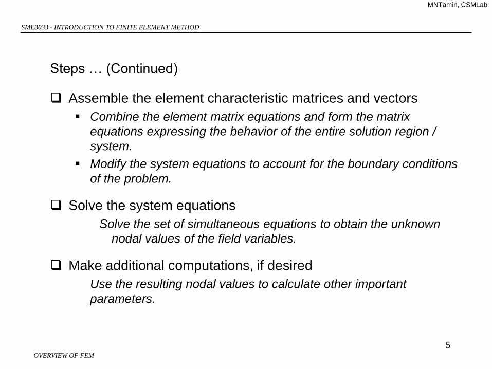
Steps … (Continued)
Assemble the element characteristic matrices and vectors
Combine the element matrix equations and form the matrix
equations expressing the behavior of the entire solution region /
system.
Modify the system equations to account for the boundary conditions
of the problem.
Solve the system equations
Solve the set of simultaneous equations to obtain the unknown
nodal values of the field variables.
Make additional computations, if desired
Use the resulting nodal values to calculate other important
parameters.

OVERVIEW OF FEM
SME3033 - INTRODUCTION TO FINITE ELEMENT METHOD
MNTamin, CSMLab
6
Select the solution domain
Discretize the continuum
Choose inerpolation functions
Derive element characteristic
matrices and vectors
Assemble element
characteristic matrices and
vectors
Solve the system equations
Make additional
computations, if desired
Draw the model geometry
Mesh the model geometry
Select element type
(The FEA software was written to do this)
Input material properties
(The computer will assemble it)
Input specified load and boundary conditions
(The compiler will solve it)
Request for output
Post-process the result file
FE procedures: FE software user steps:
OVERVIEW OF FEM
SME3033 - INTRODUCTION TO FINITE ELEMENT METHOD
MNTamin, CSMLab
7
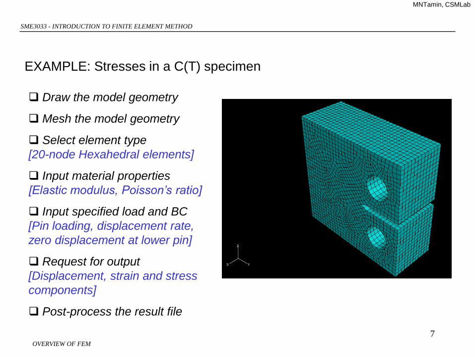
Draw the model geometry
Mesh the model geometry
Select element type
[20-node Hexahedral elements]
Input material properties
[Elastic modulus, Poisson’s ratio]
Input specified load and BC
[Pin loading, displacement rate,
zero displacement at lower pin]
Request for output
[Displacement, strain and stress
components]
Post-process the result file
EXAMPLE: Stresses in a C(T) specimen

OVERVIEW OF FEM
SME3033 - INTRODUCTION TO FINITE ELEMENT METHOD
MNTamin, CSMLab
8
EXAMPLE: Stresses in a C(T) specimen
Check for obvious mistakes/errors
Extract useful information
Explain the physics/ mechanics
OVERVIEW OF FEM
SME3033 - INTRODUCTION TO FINITE ELEMENT METHOD
MNTamin, CSMLab
9
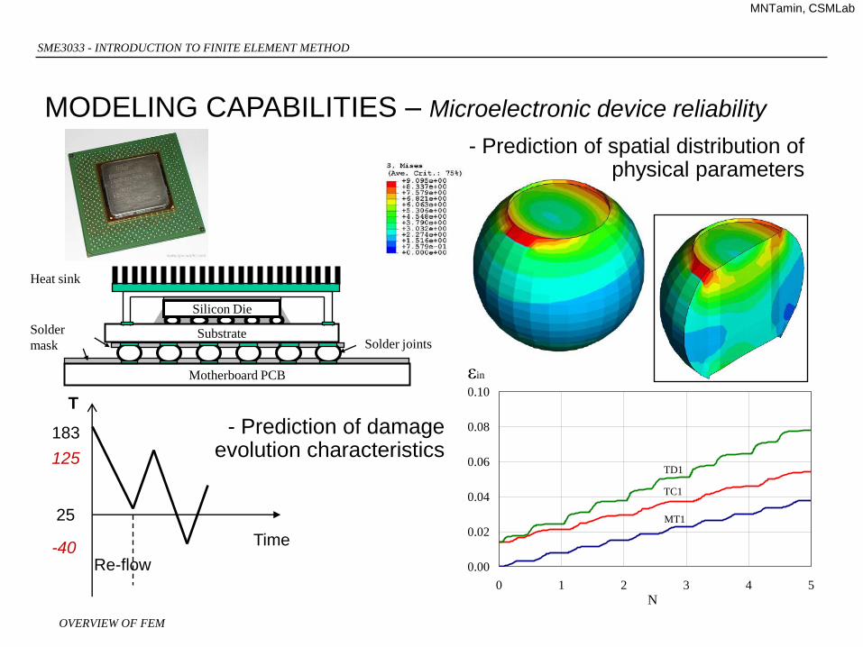
MODELING CAPABILITIES – Microelectronic device reliability
MT1
TC1
TD1
0.00
0.02
0.04
0.06
0.08
0.10
0 1 2 3 4 5
N
εin
-40
125
183
25
Re-flow
T
Time
- Prediction of spatial distribution of physical parameters
- Prediction of damage evolution characteristics
Silicon Die
Substrate
Heat sink
Motherboard PCB
Solder jointsSolder
mask
OVERVIEW OF FEM
SME3033 - INTRODUCTION TO FINITE ELEMENT METHOD
MNTamin, CSMLab
10
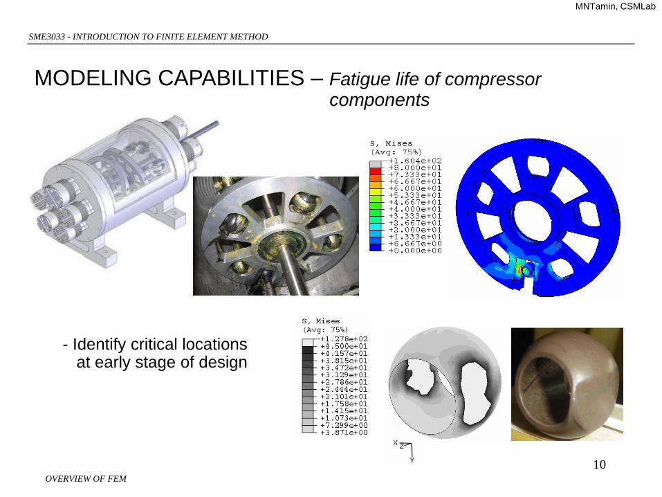
MODELING CAPABILITIES – Fatigue life of compressor components
- Identify critical locations at early stage of design
OVERVIEW OF FEM
SME3033 - INTRODUCTION TO FINITE ELEMENT METHOD
MNTamin, CSMLab
11
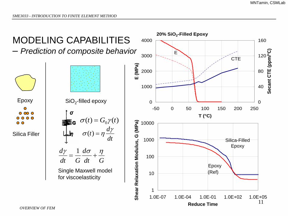
Epoxy
Silica Filler
SiO2-filled epoxy
Single Maxwell model
for viscoelasticity
)()( 0 tGt
dt
dt
)(
Gdt
d
Gdt
d
1
20% SiO2-Filled Epoxy
E
CTE
0
1000
2000
3000
4000
-50 0 50 100 150 200 250
T (°C)
E (
MP
a)
0
40
80
120
160
Se
ca
nt
CT
E (
pp
m/°
C)
Silica-Filled
Epoxy
(Ref)
Epoxy
1
10
100
1000
10000
1.0E-07 1.0E-04 1.0E-01 1.0E+02 1.0E+05
Reduce Time
Sh
ea
r R
ela
xati
on
Mo
du
lus,
G (
MP
a)
MODELING CAPABILITIES – Prediction of composite behavior
OVERVIEW OF FEM
SME3033 - INTRODUCTION TO FINITE ELEMENT METHOD
MNTamin, CSMLab
12
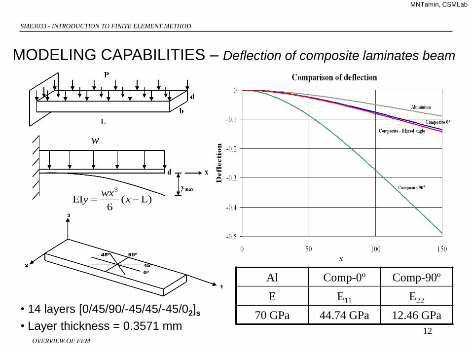
• 14 layers [0/45/90/-45/45/-45/02]s
• Layer thickness = 0.3571 mm
Al Comp-0º Comp-90º
E E11 E22
70 GPa 44.74 GPa 12.46 GPa
)L(6
EI3
xwx
y
w
MODELING CAPABILITIES – Deflection of composite laminates beam
OVERVIEW OF FEM
SME3033 - INTRODUCTION TO FINITE ELEMENT METHOD
MNTamin, CSMLab
13
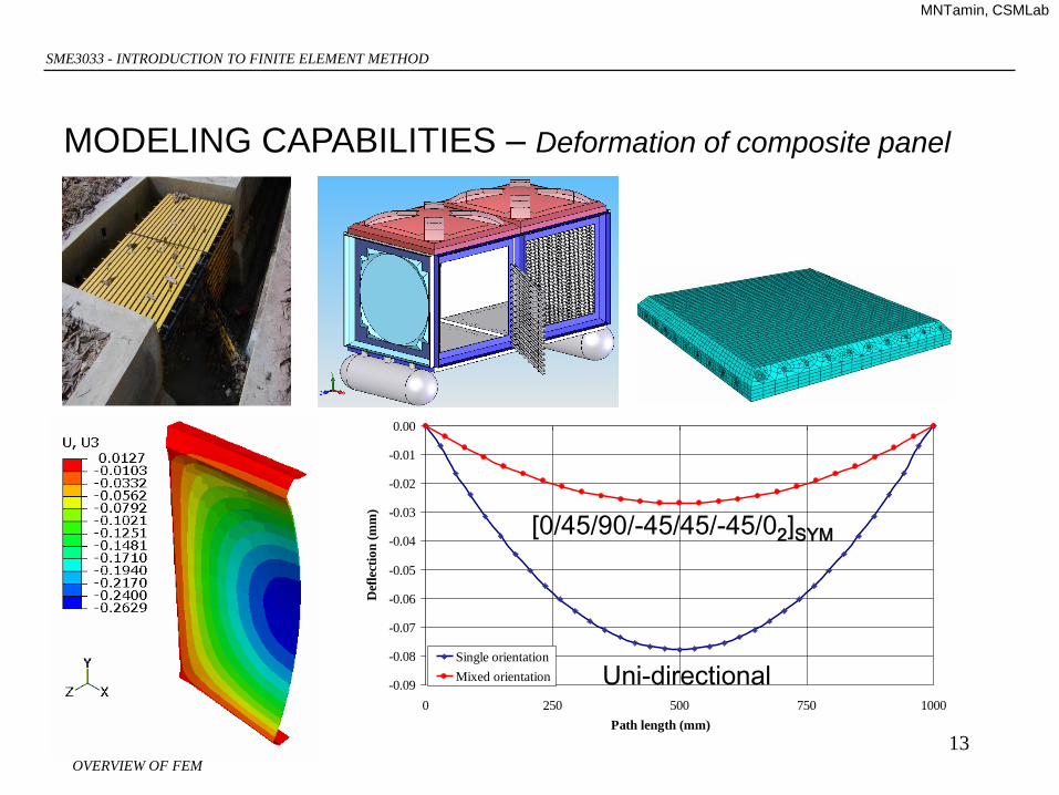
MODELING CAPABILITIES – Deformation of composite panel
-0.09
-0.08
-0.07
-0.06
-0.05
-0.04
-0.03
-0.02
-0.01
0.00
0 250 500 750 1000
Path length (mm)
Def
lect
ion
(m
m)
Single orientation
Mixed orientation Uni-directional
[0/45/90/-45/45/-45/02]SYM
OVERVIEW OF FEM
SME3033 - INTRODUCTION TO FINITE ELEMENT METHOD
MNTamin, CSMLab
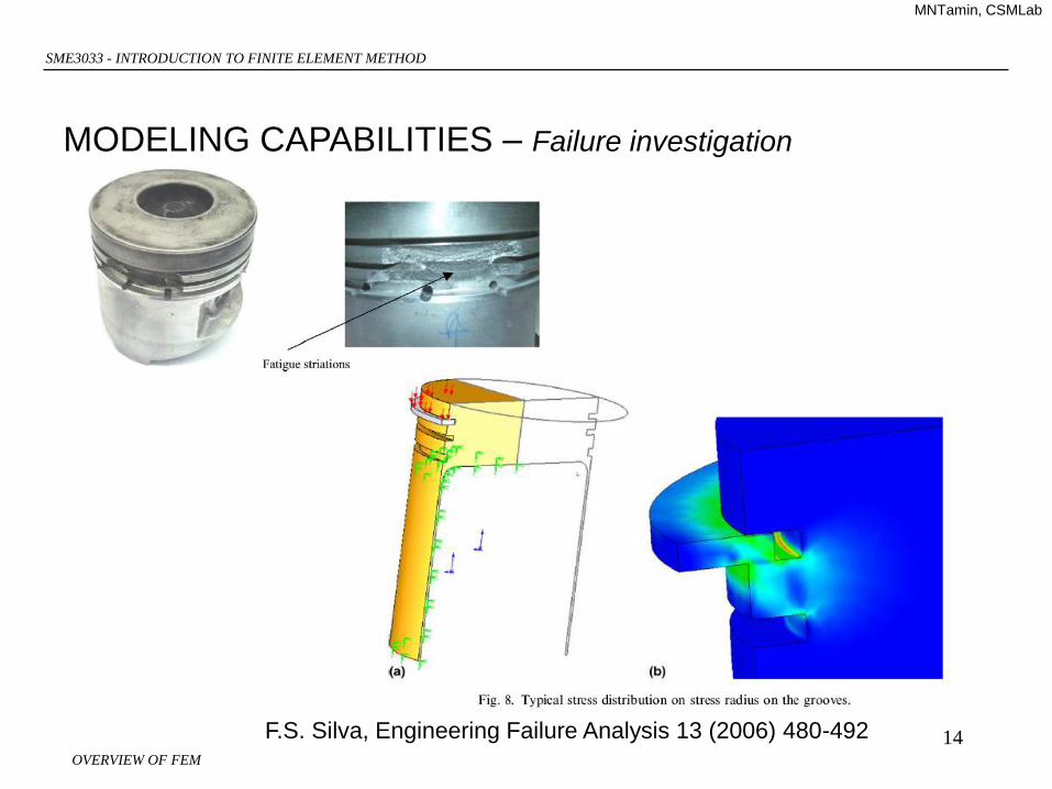
14F.S. Silva, Engineering Failure Analysis 13 (2006) 480-492
MODELING CAPABILITIES – Failure investigation

OVERVIEW OF FEM
SME3033 - INTRODUCTION TO FINITE ELEMENT METHOD
MNTamin, CSMLab
15
FINITE DIFFERENCE VERSUS FINITE ELEMENT METHOD
Finite element method:
envisions the solution region as built up of many small
interconnected sub-regions or elements.
gives a piecewise approximation to the governing equations.
Finite difference scheme:
envisions the solution region as an array of grid points.
gives a pointwise approximation to the governing equations.

OVERVIEW OF FEM
SME3033 - INTRODUCTION TO FINITE ELEMENT METHOD
MNTamin, CSMLab
16
FINITE DIFFERENCE
Finite difference scheme:
envisions the solution region as an array of grid points.
gives a pointwise approximation to the governing equations.
0
22
0
2
101112
2
211101
2
2
2
2
y
TTT
x
TTT
y
T
x
T
For node (1,1):