Embed Size (px)
Citation preview

FACILITIES ENGINEERING & CONSTRUCTION VERSION 2/1/16

JMU DESIGN PHILOSOPHY
2 | P a g e
JMU DESIGN & CONSTRUCTION GUIDELINES
is devoted to building and maintaining the most energy efficient and cost-effective university
possible. While keeping the needs of our students and staff first in every respect, we must also
consider the weight of our actions on both a local and global scale. Our efforts in reducing
overall energy demand and greenhouse gas emissions from the consumption of fossil fuels blend
seamlessly with our goal of maximizing the value of all of our facilities. Implementing the best
available technologies in every aspect of our building and site design is critical to help us best
serve our students, faculty and the local community. The delicate balance between the budget
and environmental concerns has led us to develop a campus-wide initiative to reduce our energy
consumption. JMU is at the forefront of a far-reaching effort to reduce our overall
environmental impact.
Primary attention shall be given to the reduction of energy use and water consumption by
focusing on the reduction of the total lifetime building energy load. Since alterations to a
building’s envelope are generally the most cost-prohibitive, first priority shall be given to all
concealed insulation components. Windows and doors are typically the largest contributing
factor in the building’s heating and cooling load, and quite expensive to replace; therefore
providing the most energy efficient and durable fenestration is the next priority for JMU. By
focusing on our first two challenges, the impact of the HVAC system, our third critical load
component, will be greatly reduced. Air distribution systems, and other HVAC system
components that are generally inaccessible, shall be designed with consideration for future,
more budget-friendly equipment changes.
As evidenced by our numerous existing campus buildings, we can build our buildings for more
than a 100-year life cycle. Knowing that the most efficient use of an older building is the re-use
of an older building, we are planning our university for many generations to come. Our
university is characterized by many things, one of those being our beautiful campus. As we
cherish the history and appeal of our existing Bluestone campus, we want our future generations
to embrace the work we do today in the same regard.
Our staff consists of subject matter experts from every branch of the construction industry and
we are willing and ready to help improve our campus by every available means.

PURPOSE OF GUIDELINES
3 | P a g e
JMU DESIGN & CONSTRUCTION GUIDELINES
The Construction Guidelines (JMUCG)
are intended to provide both performance-based and prescriptive guidance to the A/E and the
contractor in the planning, preparation and installation phases of all JMU construction projects.
This document is also meant to provide instruction as to certain JMU requirements that may go
above and beyond typical code requirements. These guidelines are in place to ensure the best
possible long-term outcome for JMU by creating sustainable buildings and infrastructure, while
maintaining consistency with the current campus-wide design and JMU master plan.
This document DOES NOT supersede applicable state codes, BCOM requirements or any other
governing federal, state or local laws. However, this guideline may exclude certain exceptions as
listed in the standard codes. Designers are not to reference this guideline in the project
specifications, but shall incorporate the contents of this guideline into the building and site
design. Any conflict between this document and any of the aforementioned laws or codes shall
be brought to the immediate attention of the Director of Facilities Engineering & Construction.
The architect, engineer, designer of record and/or contractor(s) shall be responsible for the
entire contents of this document. This document contains the JMU Design and Construction
Guidelines Compliance Form, and this form shall be filled out, in its entirety, then given to the
JMU Project Manager (PM) at the submission of the preliminary construction drawings. Any
deviation(s) from these guidelines shall require the exception(s) to be considered through the
submission of the JMU Design Standards Variance Form that is available from your JMU PM.
Variance requests shall provide proof of undue hardship or substantial cost-benefit reasons to be
considered by the Director of Facilities Engineering & Construction for approval.
Thank you for helping us continue our tradition of excellence at

STAFF DIRECTORY
4 | P a g e
JMU DESIGN & CONSTRUCTION GUIDELINES
Business Services Administration
Towana Moore Associate Vice President 540-568-2535
Facilities Engineering & Construction
Gary Shears Director, Engineering and Construction 540-568-2850
Facilities Management
Craig Short Director, Facilities Management;
Operations and Support Systems 540-568-6575
***Facilities Engineering***
Miranda Eppard Admin. Ass't to Engineering & Sustainability 540-568-6315
Carrie Comer Admin. Ass't to Engineering 540-568-4067
Gary Thayer Construction Engineer/PLMBG 540-568-6720
Anna Hudick Senior Mechanical Engineer/HVAC/ELEC 540-568-6738
Frank Viscomi Senior Mechanical Engineer/HVAC 540-568-3692
Tim Shantz Construction Engineer/STRUC 540-568-5909
Jared Combs Construction Engineer/ELEC 540-568-6580
Matt Black Construction Engineer/STRUC/ARCH 540-568-7290
Mike Derrow Construction Engineer/PLMBG/UTIL Locating Mgr. 540-568-7127
Dennis Kiracofe AutoCAD Supervisor 540-568-8136
Jack Martin Utility Locator 540-568-3482
John Khampavong Utility Locator 540-568-4068
Abe Kaufman Energy Conservation & Sustainability Mgr. 540-568-4201
Mike Dalmolin Sustainability Coordinator 540-568-6798
Dale Chestnut Stormwater Coordinator 540-568-7606
Brad Andrick GIS Technician 540-568-4029
Department Fax 540-568-3547
***Facilities Planning & Construction***
Tom Contos Director, Facilities Planning & Construction 540-568-3003
Julie Huffman Office Manager 540-568-3001
Scott Wachter Capital Outlay Project Manager 540-568-3006
Glenn Wayland Capital Outlay Project Manager 540-568-6345
Rick Miller Capital Outlay Project Manager 540-568-3007
Nancy Cornwell Capital Outlay Project Engineer 540-568-3008
Tim Dean Capital Outlay Project Engineer 540-568-7229
Brent Harlow Capital Outlay Project Engineer 540-568-7628
Department Fax 540-568-7969

STAFF DIRECTORY
5 | P a g e
JMU DESIGN & CONSTRUCTION GUIDELINES
***Facilities Management Operations***
Rodney Lam Assistant Director of Operations 540-568-6905
Asa Taylor Mgr. (Building Support Systems) 540-568-3337
Matthew Jefferson Senior Trades Mgr. (B.A.S., Electrical, HVAC, Plumbing) 540-568-4303
Dennis Hart Power Plant 540-568-6235
Tony Smith Mgr. (HSKPG, WM, Recycling, Pest Mgmt., Carpets) 540-568-8144
Frank Lucas Mgr. (Landscaping) 540-568-3411
Charles Lucas Mgr. (Landscaping) 540-568-7963
Robert Weese Mgr. (Central Operations) 540-568-4376
Brian Owens Mgr. (Trades) 540-568-6870
***Facilities Management Support Services***
Duane Swanson Assistant Director 540-568-3766
Lori Butler Budget Mgr. (Accounting) 540-568-6024
Charles Grimm Facility inspector I (FICAS Property Inspector) 540-568-6146
Debbie Towe Mgr. (Business Applications) 540-568-3645
Julie Bubb Senior Events Planner 540-568-4103

TABLE OF CONTENTS
6 | P a g e
JMU DESIGN & CONSTRUCTION GUIDELINES
1. General Information
1.1. Codes
1.2. Building & Site Efficiency
1.3. Hot Work & Fire Watch
1.4. Occupied Buildings
1.5. Confined Space
1.6. Inspections
1.7. Clean Air Permit Requirements
2. Architectural Requirements
2.1. Purpose
2.2. Site Design
2.3. Building Design
2.4. Acoustics
2.5. Security Control Rooms
2.6. General Security Classifications
2.7. Exterior Security
2.8. Card Readers
2.9. Custodial Areas
2.10. Equipment Rooms
2.11. Telecommunications Rooms
2.12. Maintenance Rooms
2.13. Laundry Rooms
2.14. Trash/Recycling Rooms
2.15. Loading Areas
2.16. Offices
2.17. Instructional Spaces
2.18. Restrooms
2.19. Lobbies
2.20. MSDS
2.21. Stairs
2.22. Vending Machines
2.23. Bicycle Racks
2.24. Mail Rooms
3. Abatement Procedures
3.1. Scope
3.2. Asbestos
3.3. Lead Paint
3.4. Other Material
4. Site Plan
4.1. General
4.2. Utilities
4.3. Surrounding Areas
4.4. Site Protection
4.5. Lighting
4.6. Construction Trailer
5. Construction Drawings
5.1. General
5.2. “As-Builts”
5.3. Drawing Formats
5.4. CAD Standards
5.5. CAD Drawing Structure
5.6. BIM Standards
5.7. PDF Requirements
5.8. Layering Standards
5.9. AIA Layering Format
5.10. Lines, Objects & Entities
5.11. Scale & Units
5.12. Model & Paper Space Usage
5.13. XREFS
5.14. AutoCAD Drawing Support Files
5.15. File Transmittal
5.16. Record Drawings
5.17. Error-Free AutoCAD Delivery

TABLE OF CONTENTS
7 | P a g e
JMU DESIGN & CONSTRUCTION GUIDELINES
6. Parking Lots
6.1. General
6.2. Standard Lots
6.3. Heavy Lots
6.4. Asphalt Cut & Patch
7. Landscaping
7.1. General
7.2. Plantings
7.3. Lawns
7.4. Hydro-Seeding
7.5. Drainage
7.6. Water Conservation
7.7. Design
7.8. Plants to Avoid
8. E&S Control/Stormwater
8.1. General
8.2. Plans
8.3. Project Completion
9. Excavation & Grading
9.1. Excavation
9.2. Grading
10. Utilities Locating
11. Irrigation
11.1. General
11.2. Winterization
11.3. Piping
11.4. Pipe Installation
11.5. Valve Boxes
11.6. Valves
11.7. Sleeving
11.8. Heads
11.9. Controller
11.10. Electrical
11.11. Mapping
11.12. Inspections
11.13. Repairs
12. Footings & Foundations
12.1. Footings
12.2. Foundations
13. Concrete
13.1. General
13.2. Concrete Mixes
13.3. Formwork
13.4. Slump
13.5. Placement
13.6. Interior Slabs
13.7. Sidewalks & Exterior Slabs
14. Masonry
14.1. General
14.2. Veneer
14.3. Mortar
14.4. Flashing
14.5. Grout
14.6. Accessories

TABLE OF CONTENTS
8 | P a g e
JMU DESIGN & CONSTRUCTION GUIDELINES
15. Bluestone
15.1. General
15.2. Mortar
16. Steel
16.1. General
16.2. Welding & Tensioning
16.3. Handrails & Guardrails
16.4. Stairs & Ladders
17. Thermal & Moisture
17.1. Moisture
17.2. Vapor
17.3. Thermal
17.4. Flashing
18. Fenestration
18.1. General
18.2. Hardware
18.3. Security
19. Roofing
19.1. General
19.2. Coverings
19.3. Metal
20. Life Safety
20.1. General
20.2. Fire Protection Systems
21. Building Automation Systems
21.1. General
21.2. Quality Assurance
21.3. Submittals
21.4. Coordination
21.5. System Operations
21.6. Operation & Maintenance Data
21.7. Guarantee
21.8. Approved Manufacturers
21.9. Hardware Requirements
21.10. BAS Controlled HVAC
21.11. Network
21.12. Head End Requirements
21.13. Field Installation
21.14. VFDs
21.15. Utility Metering
22. Mechanical
22.1. Design
22.2. General
22.3. Location & Equipment
22.4. Metering
22.5. Ventilation & Outdoor Air
22.6. Water Treatment
22.7. Cooling Towers
22.8. AHUs & RTUs
22.9. Fan Coil Units
22.10. VAVs
22.11. Exhaust & Make-up Air
22.12. Pumps
22.13. Split Systems
22.14. Air Filters

TABLE OF CONTENTS
9 | P a g e
JMU DESIGN & CONSTRUCTION GUIDELINES
22.15. Pipe Insulation
22.16. Refrigeration
22.17. Refrigerant Monitors
22.18. Refrigerant Management
22.19. Chillers
22.20. VFDs
22.21. Glycol
22.22. HVAC Controls
22.23. IT Computer Rooms
22.24. Environmental Chambers
22.25. Specialty Systems
22.26. ID of Equipment & Valves
22.27. Identification of Piping
22.28. Small Packaged Boilers
23. Steam
23.1. General
23.2. Condensate Pumps
23.3. Gaskets
23.4. Heating Water Converters
23.5. Flow Meters
23.6. Control Valves
23.7. Underground Piping
23.8. Humidification
23.9. Safety Relief Valves
23.10. Isolation Valves
24. Plumbing
24.1. General
24.2. Exterior Service
24.3. Interior Service
24.4. D/W/V
24.5. Valves & Fixtures
25. Electrical
25.1. General
25.2. Inspections
25.3. Service
25.4. Branch
25.5. Wiring
25.6. Exterior
25.7. Conduit
25.8. Life Safety
25.9. Generators
25.10. General Lighting
25.11. Interior Lighting
25.12. Exterior Lighting
25.13. Classrooms
25.14. Fire Alarms
26. Conveying Systems
27. Telecommunications
27.1. General
27.2. Building Telecom Entrance
27.3. MDFs & IDFs
27.4. Work Areas
27.5. Outlet Boxes
27.6. Horizontal Distribution System
27.7. Elevators
27.8. Grounding
27.9. Emergency Phones
27.10. Junction Boxes
27.11. Roof Penetrations
27.12. Wireless Access Points
27.13. Classrooms
27.14. Manhole Specifications
27.15. Buried Conduit Specifications
27.16. Completion Documents

TABLE OF CONTENTS
10 | P a g e
JMU DESIGN & CONSTRUCTION GUIDELINES
28. Finishes
28.1. Ceilings
28.2. Walls
28.3. Floors
28.4. Paint
29. Wood & Plastics
30. Interior Furnishings
30.1. Furnishings
30.2. Window Coverings
31. Signage
32. Appendix

JMU DESIGN & CONSTRUCTION GUIDELINES COMPLIANCE FORM
11 | P a g e
JMU DESIGN & CONSTRUCTION GUIDELINES
RDP/CONTRACTOR COMPLIANCE FORM
JMU Project Name: _____________________________________________________________________
Project Code #: ________________________________________________________________________
Consultant/Contractor Firm Name: ________________________________________________________
I, ______________________________________________________________ (print name), as the
registered design professional(RDP)/contractor of the aforementioned project and the authorized agent
for the aforementioned firm, do hereby certify that I have read the JMU Design and Construction
Guidelines in its entirety and have complied with all requirements therein. This includes all general and
specific design principles, as well as any included material and equipment specifications and the listed
construction drawing requirements. I also certify that any requirements that are unable to be met, for
whatever the reason, have been listed in the JMU Design Standards Variance Form and submitted to the
designated JMU PM. I also understand that any requests for variance from these guidelines must be first
approved by either the JMU Director of Facilities Engineering and Construction or the JMU Director
Facilities Planning and Construction before being implemented in the project.
RDP/Contractor Signature: _______________________________________________________________
(Please return this completed form to your JMU PM with the submission of the preliminary drawings.)

SECTION 1 - GENERAL INFORMATION
12 | P a g e
JMU DESIGN & CONSTRUCTION GUIDELINES
(1) General Information
1.1 Codes
1.1.1 The A/E is to adhere to all applicable federal, state and local codes throughout the
project.
1.1.2 This document may provide code references, exclude certain code-approved
exceptions or reference sources outside of the typical code; e.g. VDOT standards, etc.
1.1.3 This document does NOT supersede any required codes, to include, but not limited to:
1.1.3.1 The current Virginia Uniform Standard Building Code (VUSBC)
1.1.3.2 The Construction & Professional Services Manual (CPSM)
1.1.3.3 The current National Electrical Code (NEC)
1.1.3.4 All other codes or manuals referenced in any of the aforementioned codes
1.2 Building and Site Efficiency
1.2.1 All new construction and renovation shall comply with all current Executive Orders to
the extent practicable and where economically justifiable for the university.
1.2.2 All efficiency measures shall take into account the total building and site design and
incorporate those measures to give JMU the best possible lifetime payback.
1.2.3 All building efficiency measures shall take into account the projected maintenance
requirements and their associated costs into lifetime building costs.
1.2.4 Focus shall be placed on the cost-efficient reduction of energy demand through
building envelope design, while incorporating upwards compatibility for future “free-
energy devices;” e.g. PV, wind turbines, etc.
1.3 Hot Work and Fire Watch
1.3.1 Includes all welding, soldering, cutting, brazing, grinding, drilling or other methods of
construction or destruction that can produce a potential fire hazard in the presence of
flammable material in an occupied building.
1.3.2 All such work shall require a JMU Hot Work permit before work begins.
1.3.3 All hot work requires a continuous fire watch that is approved by the JMU office of
Risk Management. Fire watch shall also be required in any instance in which a fire
suppression system or fire alarm system will be deactivated, modified or limited in its
function in any capacity. Certain areas could require an extended fire watch beyond
the completion of the hot work.
1.3.4 The contractor shall provide a minimum of 48 hours of prior notice to the JMU PM for
fire watch request.
1.3.5 Comply with JMU Fire Watch procedures.
1.4 Occupied Buildings
1.4.1 All work involving occupied buildings or sites shall make primary considerations for
the safety of those occupants.
1.4.2 Any work in an occupied building that involves a restriction to the accessible route
shall provide an alternate accessible route.

SECTION 1 - GENERAL INFORMATION
13 | P a g e
JMU DESIGN & CONSTRUCTION GUIDELINES
1.5 Confined Space
1.5.1 All confined space work shall comply with chapter 140 of the Virginia Administrative
Code, the “Virginia Confined Space Standard for the Construction Industry.”
1.6 Inspections
1.6.1 The JMU Project Manager (PM) will generally perform project inspections, in keeping
with regulations as found in the CPSM. However, Facilities Engineering will perform
additional periodic inspections of projects. These inspections are for code compliance
issues. Facilities Engineering personnel are state certified building and trade
inspectors.
1.7 Clean Air Permit Requirements
1.7.1 JMU currently operates under a Federal Title V operating permit. This permit
classifies JMU as a potentially hazardous air pollutant source and the permit
conditions reduce this potential with both practical and federally enforceable
measures. Therefore, JMU must closely monitor all stationary polluting equipment
that is replaced or installed on JMU property. The submittals and emissions
calculations for all such equipment shall be closely reviewed and approved prior to
installation, allowing JMU to determine the impact to our current permit.
Additionally, all internal combustion engines shall meet the EPA regulations in 40 CFR
Parts 40, 85 Standard of Performance for Stationary Compression Ignition Internal
Combustion Engines. JMU will be required to submit an Air Permit Application (Form
7) for every piece of stationary polluting equipment that is owned or installed at JMU.
This can be submitted as a group for major projects or independently per piece of
equipment. The A/E and/or contractor shall submit the required information for all
polluting equipment regardless of size. Pollutant sources to be considered are, but
not limited to: natural gas, diesel oil, wood, coal or trash.
***END OF SECTION 1***
SECTION 2 - ARCHITECTURAL
14 | P a g e
JMU DESIGN & CONSTRUCTION GUIDELINES
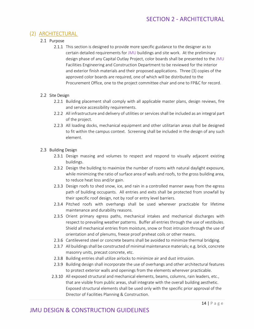
(2) ARCHITECTURAL
2.1 Purpose
2.1.1 This section is designed to provide more specific guidance to the designer as to
certain detailed requirements for JMU buildings and site work. At the preliminary
design phase of any Capital Outlay Project, color boards shall be presented to the JMU
Facilities Engineering and Construction Department to be reviewed for the interior
and exterior finish materials and their proposed applications. Three (3) copies of the
approved color boards are required, one of which will be distributed to the
Procurement Office, one to the project committee chair and one to FP&C for record.
2.2 Site Design
2.2.1 Building placement shall comply with all applicable master plans, design reviews, fire
and service accessibility requirements.
2.2.2 All infrastructure and delivery of utilities or services shall be included as an integral part
of the project.
2.2.3 All loading docks, mechanical equipment and other utilitarian areas shall be designed
to fit within the campus context. Screening shall be included in the design of any such
element.
2.3 Building Design
2.3.1 Design massing and volumes to respect and respond to visually adjacent existing
buildings.
2.3.2 Design the building to maximize the number of rooms with natural daylight exposure,
while minimizing the ratio of surface area of walls and roofs, to the gross building area,
to reduce heat loss and/or gain.
2.3.3 Design roofs to shed snow, ice, and rain in a controlled manner away from the egress
path of building occupants. All entries and exits shall be protected from snowfall by
their specific roof design, not by roof or entry level barriers.
2.3.4 Pitched roofs with overhangs shall be used wherever practicable for lifetime
maintenance and durability reasons.
2.3.5 Orient primary egress paths, mechanical intakes and mechanical discharges with
respect to prevailing weather patterns. Buffer all entries through the use of vestibules.
Shield all mechanical entries from moisture, snow or frost intrusion through the use of
orientation and of plenums, freeze proof preheat coils or other means.
2.3.6 Cantilevered steel or concrete beams shall be avoided to minimize thermal bridging.
2.3.7 All buildings shall be constructed of minimal maintenance materials; e.g. brick, concrete
masonry units, precast concrete, etc.
2.3.8 Building entries shall utilize airlocks to minimize air and dust intrusion.
2.3.9 Building design shall incorporate the use of overhangs and other architectural features
to protect exterior walls and openings from the elements wherever practicable.
2.3.10 All exposed structural and mechanical elements, beams, columns, rain leaders, etc.,
that are visible from public areas, shall integrate with the overall building aesthetic.
Exposed structural elements shall be used only with the specific prior approval of the
Director of Facilities Planning & Construction.

SECTION 2 - ARCHITECTURAL
15 | P a g e
JMU DESIGN & CONSTRUCTION GUIDELINES
2.4 Acoustics
2.4.1 All renovations and new construction shall be designed to comply with requirements
and recommendations of “ANSI/ASA S12.60-2010/Part 1 American National Standard
Acoustical Performance Criteria, Design Requirements, and Guidelines for Schools, Part
1: Permanent Schools.” A/E shall, by submitting preliminary design documents for
approval and again by stamping and signing construction documents, stipulate full
compliance of the design and full inclusion of all necessary conformance testing for
each and every space in the authorized commissioning plan. Designing to and testing
conformance of the performance of building spaces and systems is part of basic design
services.
2.4.2 Installation of noise-generating devices (telephone, vending machines, etc.) should be
avoided on the adjoining walls between any rooms requiring acoustical privacy. Such
devices shall not be located in common hallways or corridor areas adjacent to noise
sensitive areas.
2.4.3 Back-to-back utility installations shall be avoided. Place these installations a minimum
of one stud bay apart to minimize sound transmission.
2.4.4 Walls at faculty and/or management level staff offices shall extend to floor/ceiling
level above.
2.4.5 Required acoustical isolation shall extend behind recessed fixtures of any type; e.g.
medicine cabinets, fire extinguisher cabinets, electric panels, drinking fountains,
bookcases, etc.
2.5 Security Control Rooms
2.5.1 Security rooms shall be provided to house and protect the main control equipment
for required life safety systems; e.g. fire alarms, security systems, card readers and
surveillance/security cameras.
2.5.2 There shall be one security room per floor.
2.5.3 Each security room shall a minimum of 100ft2.
2.5.4 There shall be no accessory use of the room permitted without prior approval.
2.5.5 The security room on each floor shall be interconnected and vertically aligned with
the security room(s) above and below.
2.5.6 The interconnection shall be (3) 4” conduit runs not to exceed 25’ in length. Each
conduit run shall also be provided with no less than one additional pull string that is
clearly marked.
2.5.7 Each security room shall be provided with two (2) communications outlets.
2.5.8 Each security room shall be provided with a minimum of three (3) separate electrical
circuits, with each circuit rated at a minimum of 20 amps.
2.5.9 All security rooms shall be supplied with emergency lighting and power.
2.6 Security Classifications
2.6.1 Level One (public and semi-public spaces) - This classification applies to public spaces
with intense traffic and no clear ownership definition; e.g. areas without card access
or otherwise locked entry doors, lobbies, unrestricted corridors, vestibules,
classrooms, stairs, elevators, public restrooms, food service facilities, bookstores,

SECTION 2 - ARCHITECTURAL
16 | P a g e
JMU DESIGN & CONSTRUCTION GUIDELINES
recreational and parking facilities, assembly areas and conference rooms. The
following minimum security measures are required for Level One spaces:
2.6.1.1 Clearly posted hours of operation
2.6.1.2 Well lit entries, lobbies and corridors
2.6.1.3 High visibility into spaces before entering
2.6.1.4 Doors lockable by only JMU maintenance staff or JMU police.
2.6.1.5 Visibility from adjacent occupied spaces
2.6.1.6 Emergency telephones linked to JMU police
2.6.1.7 Easily identifiable and accessible egress paths
2.6.1.8 Fire and smoke alarm systems
2.6.2 Level Two (private and locked semi-public spaces) - This classification applies to parts
of a facility may be secured by locked doors, areas where traffic flow is smaller and
more controlled and more valuable equipment and/or risk factors are involved.
Examples of private spaces at this level include faculty & staff offices, teaching labs,
exercise facilities, health and safety areas, lecture hall preparation areas, projection
booths, dark rooms, private toilets, special collection areas, campus operation and
maintenance spaces, building mechanical/electrical/telecommunication spaces, etc.
In addition to security measures recommended for level one, these areas should
include the following:
2.6.2.1 Secured doors with inside vandal-proof or pinned hinges and latch guard.
2.6.2.2 Lockable windows.
2.6.2.3 Controlled/programmable keying system.
2.6.2.4 Non-lift sliding windows or doors (if used).
2.6.3 Level Three (secure spaces)-This level applies to high equipment holding spaces,
special collection areas, high exhibit spaces, supply rooms, computer mainframe
rooms, special secure areas, confidential file rooms, vaults, etc. The security
requirements for these spaces shall be determined on a case by case basis, but as a
general rule of thumb, the following shall be considered in addition to all security
features noted for levels one and two:
2.6.3.1 Motion sensors.
2.6.3.2 Intrusion alarms.
2.6.3.3 Electronic surveillance.
2.6.3.4 Time clock access restrictions.
2.6.3.5 Security guard/patrol intervals.
2.6.3.6 Special ID detection/access system.
2.7 Exterior security
2.7.1 The protection of people and vehicles at building exteriors is extremely important.
Security at walkways, entries, loading and unloading areas, near ground floor
windows, and at building indentations can be significantly enhanced by applying the
same principles followed in the design of other public spaces.

SECTION 2 - ARCHITECTURAL
17 | P a g e
JMU DESIGN & CONSTRUCTION GUIDELINES
2.8 Card Readers
2.8.1 In all new and remodeled buildings, install one labeled, 2” empty conduit from
building telecommunication room to main electrical room.
2.8.2 For all building entrances and computer laboratories, provide a 4” square box, with a
single gang plastic ring, served by ¾” conduit to the security control room. Label
conduit for use with a future card reader system. Mount boxes on strike side of each
entrance. This is in addition to all the required infrastructure for security, resultant
emergency existing devices, electric strikes, etc.
2.9 Custodial Areas
2.9.1 One custodial closet shall be provided per 10,000ft2 of floor area, per story, for every
story of new buildings. When multiple closets are required per story, provide a
minimum distance of 300’ feet between closets.
2.9.2 Custodial closets should be located near elevators and restrooms, and centralized
among the areas they will serve. Do not locate custodial closets on stairway landings.
2.9.3 Entrances to custodial closets through restrooms, mechanical rooms or similar
intermediate spaces or vice versa are not permitted.
2.9.4 The typical custodial closet floor needs to be a minimum of 80ft2 with no less than an
8’ dimension in any direction, with a minimum clear ceiling height of 9’.
2.9.5 Do not locate the components of any telecommunications, electrical or mechanical
systems in custodial closets. Closets shall be dedicated to custodial functions only.
Accessory roof hatch access shall be permitted.
2.9.6 A large capacity Terrazzo floor sink with stainless steel rim, stainless steel splash
protectors, hot, cold and tempered running water and a floor drain shall be provided in
each custodial closet. Sinks are best located near the door, and should be positioned
so that cleaning machines and equipment can be maneuvered easily and emptied into
the sink prior to being refilled. Blocking shall be provided at the wall beside the floor
sink for chemical dispenser.
2.9.7 Provide shelving on at least 3 walls for a minimum of 15 lineal feet, each with a
minimum of a 14” vertical clearance between shelves. Mop hangers, mop racks, hose
racks and broom racks shall also be provided. Blocking shall be provided for all shelves
and location is to be coordinated with the building owner.
2.9.8 In addition to the wet custodial closet, a 120ft2 custodial supply storage room shall be
provided for each building. This room should be located in proximity to the elevator.
2.9.9 In addition to, or in conjunction with the custodial supply storage room, each facility
shall be provided with a custodial staff area. This area shall include lockers, a table,
chairs, a sink, cabinetry, countertops, at least one receptacle outlet for countertop
equipment, a bulletin board and a wall clock. Size and location of the area shall be
verified and confirmed by the project manager.
2.9.10 Provide a 36” door that opens outward, not to restrict any code-required emergency
egress paths.

SECTION 2 - ARCHITECTURAL
18 | P a g e
JMU DESIGN & CONSTRUCTION GUIDELINES
2.10 Equipment Rooms
2.10.1 At each mechanical, electrical, elevator, substation or penthouse equipment room,
provide at least one (1) communications outlet with adjacent 125 volt GFCI duplex
outlet.
2.10.2 Equipment room layouts shall indicate graphically how servicing, operation and repair
clearances are assigned. These graphic representations shall include all necessary
carrying beam, crane and/or pick-point locations.
2.10.3 Provide a minimum of a 4” housekeeping pad for all floor-mounted equipment.
2.10.4 Locate all equipment to provide an ample and clearly defined circulation path for the
removal, repair and replacement of equipment. Provide all necessary structural and
finish elements needed to allow for the movement of associated devices and
equipment.
2.10.5 Access to equipment rooms shall be through the use of full height doors and/or direct
staircases from the exterior or main corridor. Equipment room egress paths shall be
clearly diagrammed on preliminary drawings.
2.10.6 Rooms and their access routes shall be designed to allow the largest piece of equipment
to be removed and replaced without having to remove any permanent walls or other
large, functioning equipment.
2.11 Telecommunication Rooms
2.11.1 See Section 27.
2.12 Maintenance Rooms
2.12.1 Every new building or major remodel project shall include a maintenance material
storage room.
2.12.2 Rooms shall be 100ft2, with no less than a 7’dimension in any direction and shall have
a minimum of a 9’ clear ceiling height.
2.12.3 Each room shall have a minimum of a 36” wide entry door.
2.12.4 Locate the maintenance materials storage room near the service entry.
2.12.5 Semi-gloss paint is a minimum wall finish.
2.13 Laundry Rooms
2.13.1 Shall be designed so that routine maintenance shall be able to be performed without
having to move the unit or any adjacent units.
2.14 Trash and Recycling
2.14.1 A recycling room of approximately 100ft2 shall be provided in each facility, with no
dimension less than 7’ allowed in any direction. This room shall be located near the
loading/service area.
2.14.2 All trash and recycling areas shall be sheltered from the wind and easily accessible by
custodial staff. Locations shall consider the unpleasant odors often generated by these
spaces. Approved screening is required in all trash collection areas.
2.14.3 Provide hot and cold hose bibs with backflow prevention, floor drains and impermeable
floor and wall coverings.

SECTION 2 - ARCHITECTURAL
19 | P a g e
JMU DESIGN & CONSTRUCTION GUIDELINES
2.15 Loading Areas
2.15.1 All new facilities shall be provided with adequate off-street service loading and
unloading areas.
2.15.2 Loading facilities shall allow the use of multiple scales of delivery. Access shall be
provided on grade or with ramps for hand truck or cart deliveries to the loading area.
2.15.3 Interior and exterior staging, packaging, unpacking and temporary storage areas for
loading and unloading shall be included in all facilities.
2.15.4 Truck cargo door loading bays shall provide inflatable air sealing devices to account for
varying truck dimensions and provide full weather protection.
2.15.5 Truck loading bays shall be 48” above grade and incorporate truck levelers when
necessary.
2.15.6 One (1) communications outlet shall be placed at the entrance of loading areas for
delivery drivers to notify JMU personnel of a delivery.
2.16 Offices
2.16.1 Faculty and managerial level staff office areas shall include space and services to allow
provisions for a desk, a credenza, a 48” wide lateral file, a 48” square white board and
at least 40 linear feet of adjustable shelving.
2.16.2 Each office shall have receptacle outlets on every wall.
2.16.3 Each office shall have a minimum of two (2) communications outlets, on opposing walls,
for each 100ft2 of space and one (1) additional communication outlet for each
additional 100ft2, or portion thereof, for telephone, data and video.
2.17 Instructional Spaces
2.17.1 Lighting shall be designed to allow presentation on white boards and projection
screens with concurrent note taking and fully lit classroom functions.
2.17.2 General-purpose classroom equipment shall include, but not be limited to, the
following:
2.17.2.1 Instructor area desk and podium with A/V connection, power and
communications outlet
2.17.2.2 Fully-seasoned chalkboards, “smart boards” and/or marker boards
2.17.2.3 Tackable display surfaces
2.17.2.4 Student seating (verify type and orientation on a room-by-room basis)
2.17.2.5 Trash and recycling receptacles near the classroom
2.17.2.6 Motorized retractable projection screen
2.17.2.7 Wall Clock
2.17.2.8 Communications outlets with adjacent power outlets (verify quantities and
locations on a room by room basis)
2.17.2.9 Ceiling mounted data/video display unit, associated infrastructure and
associated voice augmentation
2.17.2.10 General purpose electrical outlets for both operation and maintenance
2.17.2.11 A minimum of one room in every building shall be provided with distance
learning equipment infrastructure. This infrastructure shall include space
SECTION 2 - ARCHITECTURAL
20 | P a g e
JMU DESIGN & CONSTRUCTION GUIDELINES
availability, system capability, structural capacity and pathways of cameras,
control/operation areas monitors, projection devices, etc.
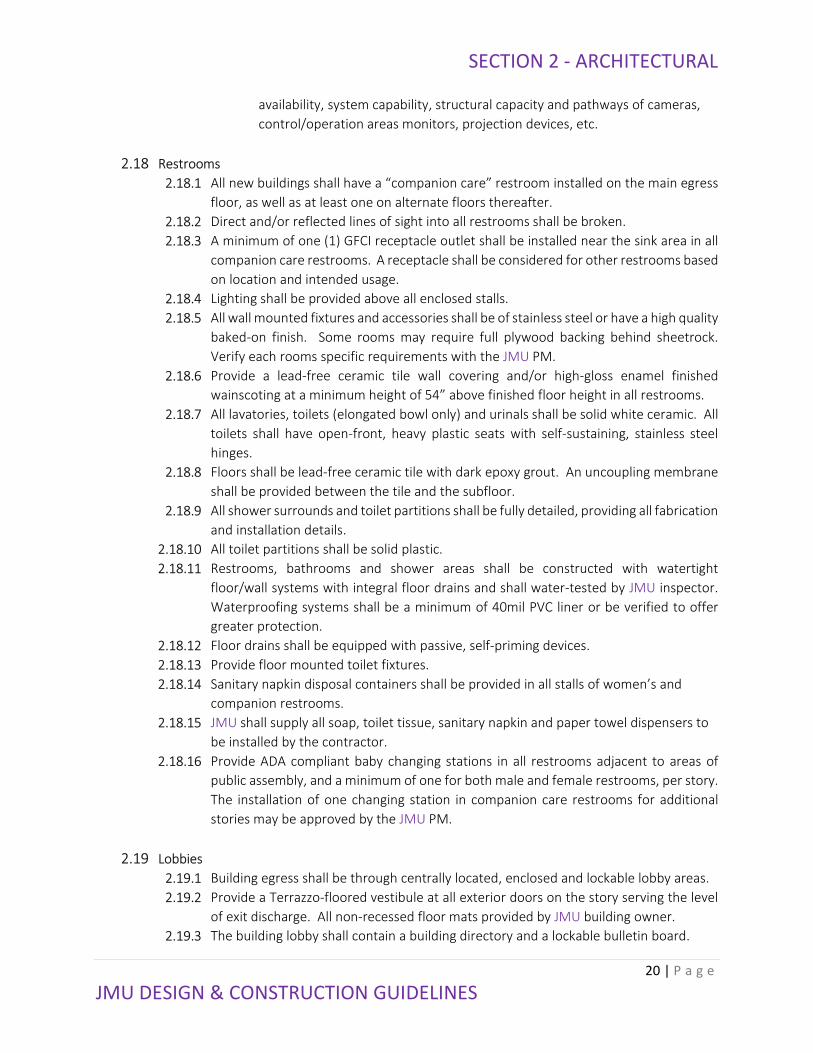
2.18 Restrooms
2.18.1 All new buildings shall have a “companion care” restroom installed on the main egress
floor, as well as at least one on alternate floors thereafter.
2.18.2 Direct and/or reflected lines of sight into all restrooms shall be broken.
2.18.3 A minimum of one (1) GFCI receptacle outlet shall be installed near the sink area in all
companion care restrooms. A receptacle shall be considered for other restrooms based
on location and intended usage.
2.18.4 Lighting shall be provided above all enclosed stalls.
2.18.5 All wall mounted fixtures and accessories shall be of stainless steel or have a high quality
baked-on finish. Some rooms may require full plywood backing behind sheetrock.
Verify each rooms specific requirements with the JMU PM.
2.18.6 Provide a lead-free ceramic tile wall covering and/or high-gloss enamel finished
wainscoting at a minimum height of 54” above finished floor height in all restrooms.
2.18.7 All lavatories, toilets (elongated bowl only) and urinals shall be solid white ceramic. All
toilets shall have open-front, heavy plastic seats with self-sustaining, stainless steel
hinges.
2.18.8 Floors shall be lead-free ceramic tile with dark epoxy grout. An uncoupling membrane
shall be provided between the tile and the subfloor.
2.18.9 All shower surrounds and toilet partitions shall be fully detailed, providing all fabrication
and installation details.
2.18.10 All toilet partitions shall be solid plastic.
2.18.11 Restrooms, bathrooms and shower areas shall be constructed with watertight
floor/wall systems with integral floor drains and shall water-tested by JMU inspector.
Waterproofing systems shall be a minimum of 40mil PVC liner or be verified to offer
greater protection.
2.18.12 Floor drains shall be equipped with passive, self-priming devices.
2.18.13 Provide floor mounted toilet fixtures.
2.18.14 Sanitary napkin disposal containers shall be provided in all stalls of women’s and
companion restrooms.
2.18.15 JMU shall supply all soap, toilet tissue, sanitary napkin and paper towel dispensers to
be installed by the contractor.
2.18.16 Provide ADA compliant baby changing stations in all restrooms adjacent to areas of
public assembly, and a minimum of one for both male and female restrooms, per story.
The installation of one changing station in companion care restrooms for additional
stories may be approved by the JMU PM.
2.19 Lobbies
2.19.1 Building egress shall be through centrally located, enclosed and lockable lobby areas.
2.19.2 Provide a Terrazzo-floored vestibule at all exterior doors on the story serving the level
of exit discharge. All non-recessed floor mats provided by JMU building owner.
2.19.3 The building lobby shall contain a building directory and a lockable bulletin board.

SECTION 2 - ARCHITECTURAL
21 | P a g e
JMU DESIGN & CONSTRUCTION GUIDELINES
2.19.4 Provide terrazzo flooring at all lobbies and, at a minimum, all floor areas serving the
main egress path.
2.19.5 Egress doors shall be recessed or protected by canopies and wing walls.
2.19.6 Provisions shall be made to provide safe and maintenance-friendly access to all lighting
fixtures in lobbies, atriums and other such high-ceiling, high-volume spaces.
2.20 MSDS
2.20.1 Material Safety Data Sheets (MSDS) for all materials used in the project shall be
submitted to the university with the construction documents in accordance with
federal regulations.
2.21 Stairs
2.21.1 The use of rubber tread covers with integral risers, stringer skirts and/or rubber
flooring at landings will be considered for stairs.
2.22 Vending Machines
2.22.1 Vending machines shall not be located in corridors. Where vending machines are
authorized, the A/E shall design all appropriate power, water, drains and a
communications outlet.
2.22.2 All vending machines shall be Energy Star rated.
2.23 Bicycle Racks
2.23.1 Campus racks are being standardized to the “Inverted-U” style. Coordinate with JMU
PM as to the space requirements for bicycle racks.
2.23.2 Provide bicycle rack space to account for 5% of the peak building or space occupant
load.
2.23.3 Provide adequate space for bicycle racks within 50’ of the main entry door.
2.23.4 Coordinate with JMU PM as to whether bicycle racks will be contractor or JMU
provided and installed.
2.23.5 Whenever possible, provide racks in a covered area and convenient to area bicycle
paths.
2.24 Mail Rooms
2.24.1 Consideration for mailrooms shall be addressed with the JMU PM and the Mail
Services director in the preliminary design phase.
***END OF SECTION 2***
SECTION 3 - ABATEMENT
22 | P a g e
JMU DESIGN & CONSTRUCTION GUIDELINES
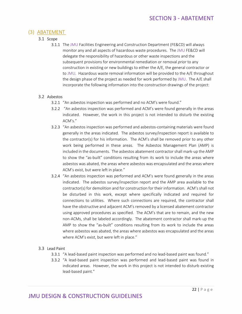
(3) ABATEMENT
3.1 Scope
3.1.1 The JMU Facilities Engineering and Construction Department (FE&CD) will always
monitor any and all aspects of hazardous waste procedures. The JMU FE&CD will
delegate the responsibility of hazardous or other waste inspections and the
subsequent provisions for environmental remediation or removal prior to any
construction in existing or new buildings to either the A/E, the general contractor or
to JMU. Hazardous waste removal information will be provided to the A/E throughout
the design phase of the project as needed for work performed by JMU. The A/E shall
incorporate the following information into the construction drawings of the project:
3.2 Asbestos
3.2.1 “An asbestos inspection was performed and no ACM’s were found.”
3.2.2 “An asbestos inspection was performed and ACM’s were found generally in the areas
indicated. However, the work in this project is not intended to disturb the existing
ACM’s.”
3.2.3 “An asbestos inspection was performed and asbestos-containing materials were found
generally in the areas indicated. The asbestos survey/inspection report is available to
the contractor(s) for his information. The ACM’s shall be removed prior to any other
work being performed in these areas. The Asbestos Management Plan (AMP) is
included in the documents. The asbestos abatement contractor shall mark-up the AMP
to show the “as-built” conditions resulting from its work to include the areas where
asbestos was abated, the areas where asbestos was encapsulated and the areas where
ACM’s exist, but were left in place.”
3.2.4 “An asbestos inspection was performed and ACM’s were found generally in the areas
indicated. The asbestos survey/inspection report and the AMP area available to the
contractor(s) for demolition and for construction for their information. ACM’s shall not
be disturbed in this work, except where specifically indicated and required for
connections to utilities. Where such connections are required, the contractor shall
have the obstructive and adjacent ACM’s removed by a licensed abatement contractor
using approved procedures as specified. The ACM’s that are to remain, and the new
non-ACMs, shall be labeled accordingly. The abatement contractor shall mark-up the
AMP to show the “as-built” conditions resulting from its work to include the areas
where asbestos was abated, the areas where asbestos was encapsulated and the areas
where ACM’s exist, but were left in place.”
3.3 Lead Paint
3.3.1 “A lead-based paint inspection was performed and no lead-based paint was found.”
3.3.2 “A lead-based paint inspection was performed and lead-based paint was found in
indicated areas. However, the work in this project is not intended to disturb existing
lead-based paint.”

SECTION 3 - ABATEMENT
23 | P a g e
JMU DESIGN & CONSTRUCTION GUIDELINES
3.3.3 “A lead-based paint inspection was performed and lead-based paint was found in the
areas indicated. The lead-based paint shall be removed prior to any other work being
performed in these areas. The contractor shall be responsible for compliance with all
requirements of the Virginia Occupational and Health Administration regulations
regarding lead-based paint protection for workers”
3.3.4 “A lead-based inspection was performed and lead based paint was found in the areas
indicated. Lead-based paint shall not be disturbed in this work except where specifically
indicated and required for connections to utilities. Where such connections are
required, contractor shall have the obstructive and adjacent lead-based paint removed
by a licensed lead-based paint abatement contractor using approved procedures as
required by VOSHA. The lead-based paint that remains and new non lead-based paint
areas shall be labeled accordingly.”
3.4 Other Material
3.4.1 All environmental remediation and/or removal of all other waste materials shall
conform to their applicable federal, state and local laws.
***END OF SECTION 3***

SECTION 4 - SITE
24 | P a g e
JMU DESIGN & CONSTRUCTION GUIDELINES
(4) SITE
4.1 General
4.1.1 Do not commence site cleaning operations until temporary erosion and sediment
control and plant protection measures are in place.
4.1.2 Protect and maintain JMU owned benchmarks and survey control points from
disturbance throughout entire construction process.
4.1.3 JMU reserves the right to salvage material and equipment. The A/E shall consult with
the JMU PM to determine needs per individual project.
4.1.4 Each project shall have an appropriate sign identifying the project name and scope.
Sign shall be visible from the public way outside of the construction fence and its
location shall be approved by JMU Director of FP&C.
4.1.5 All debris shall be removed from the site and hauled off campus. All paved areas shall
be thoroughly washed. This level of cleanliness shall be maintained throughout the
maintenance period.
4.2 Utilities
4.2.1 All underground utilities design shall be conceived and designed with an “easement
approach” in mind, thus facilitating their maintenance and accessibility. The schematic
design utility site plan and all other utility site plans thereafter shall clearly indicate the
outline of this utility easement.
4.2.2 The contractor shall secure, at the contractor’s expense, all utilities hookups and access
roads for all construction projects. The contractor shall be required to make all utility
connections and is responsible for the removal of all connections and any repairs that
may need to be made. This work is to be scheduled with the JMU PM.
4.2.3 Connections made to JMU systems shall require our prior approval as to the location,
manner and time of the connections. Connections and reinstatements requiring any
shutdown of an existing JMU system shall require the shutdown to be done only by JMU
personnel. A 14-day advance written notice shall be submitted to JMU PM and shall be
approved prior to any connections being made.
4.2.4 As soon as temporary connections are no longer required, they shall be immediately
removed by the contractor.
4.2.5 All utility connections to JMU utilities shall be metered and charged at the current rates.
The contractor shall supply and install all metering devices. Metering devices shall be
periodically inspected and read by JMU personnel throughout the entire project. Any
changes, replacements or alterations to any metering devices shall first be approved by
the JMU PM prior to the changes being made. Meters shall be installed in accessible
location.
4.2.6 Steam connections shall provide for condensate return to the JMU system.
4.2.7 As-built drawings shall mark all located lines, whether new or existing.
4.2.8 Provide metal-backed warning tape at all underground utility lines. Tape shall be
located at half of the distance between the top of the utility line and the approved
finished grade height as shown on the site plan.
4.2.9 Provide a #10 green insulated conductor in all utility trenches, regardless of the type
of piping it contains. Both ends of the wire shall be accessible and of sufficient length
SECTION 4 - SITE
25 | P a g e
JMU DESIGN & CONSTRUCTION GUIDELINES
to provide grade-level access, and be contained within approved junction boxes or
manholes.
4.2.10 Manhole covers shall be designed to VDOT load bearing requirements and shall
include identification of the system involved (steam, sanitary sewer, storm drains,
electric, telecom, etc.) All manholes shall be at least to ground level.
4.3 Surrounding Areas
4.3.1 Do not close or obstruct streets, pedestrian walkways or other any adjacent facilities
without direct permission from the Director of Facilities Engineering & Construction.
4.3.2 Provide alternative route around closed or obstructed traffic ways or sidewalks.
4.3.3 Provide traffic and/or pedestrian signage in the event an alternate or otherwise altered
route is provided.
4.3.4 Minimize interference, to the greatest extent possible, with all adjoining roads,
streets, walks and other adjacent occupied facilities during excavation operations.
4.4 Site Protection
4.4.1 Standard construction site fencing should be 8’ foot chain link fencing with top rail and
a sight-restrictive fabric screening.
4.4.2 All chain link fencing and gates shall be made of 9 gauge, 2” weave with Class 2 hot-
dipped galvanized wiring. Fencing shall be black vinyl coated.
4.4.3 All posts and rails shall be at least Schedule 40 hot-dipped galvanized or high-tensile
galvanized steel piping. Posts shall be driven and all exposed metal painted black. Top
and bottom rails shall also be painted black. All gates and hardware shall also be
painted black.
4.4.4 All construction gates should be double locked using contractor and JMU supplied locks.
4.5 Lighting
4.5.1 Facilities engineering will provide the concrete base detail for lighting units. Pole base
detail is located in the Appendix.
4.5.2 All other site lighting details are located in the electrical section.
4.6 Construction Trailer
4.6.1 Location shall be approved prior to mobilization and shown on site plan.
4.6.2 Provide a full mobilization plan at the preliminary drawing phase.
4.6.3 Contractor shall contact the local telephone company for service, telephones and fax
machines, etc. The contractor will be permitted to access the telephone company via
JMU’s telecommunication system. This shall be coordinated with the JMU PM.
***END OF SECTION 4***

SECTION 5 - DRAWINGS
26 | P a g e
JMU DESIGN & CONSTRUCTION GUIDELINES
(5) CONSTRUCTION DRAWINGS
5.1 General
5.1.1 All drawings prepared for projects within JMU Main Campus boundaries shall be tied
to the JMU Survey Control Network. Drawings shall show JMU control network point
used in addition to project specific control points established by the project Surveyor.
All drawings shall have the meridian based on the JMU Survey Control Network. JMU
will provide control point information within the project area. The JMU Survey
Control Network is based on Virginia State Plane Grid System, North Zone, U.S. Survey
Foot. Horizontal control is NADA83-CORS96-EPOCH2002.0000. Vertical control is
NAVD88 (geiod03) U.S. Survey Foot.
5.1.2 For projects outside of JMU Main Campus boundaries, it shall be the responsibility of
the A/E to establish control points within the project area. All control points
established shall be based Virginia State Plane Grid System South Zone U.S Survey
Foot. Horizontal control shall be NAD83-CORS96-EPOCH2002.0000. Vertical control
shall be NAVD88 U.S. Survey Foot.
5.1.3 FM does not loan drawings of any type. The engineering drafting department will
make one copy of any required drawings to assist the A/E. Additional copies shall be
the responsibility of the A/E and/or the contractor. Any requests for copies of
drawings shall be coordinated through the JMU PM. Electronic drawings will be
provided if available.
5.1.4 Two (2) sets of approved full construction drawings and specifications shall be
submitted to JMU at the beginning of the project.
5.1.5 Provide a digital copy of each phase of the plans in PDF format, in addition to the
required hard copies.
5.1.6 All project specifications shall be provided in PDF format (preferred) or in the most
current version of Microsoft Word for windows format.
5.1.7 Current bid documents are to be dated with the actual date of final submission
incorporating the review comments by applicable university reviews.
5.1.8 All drawings shall include the following details:
5.1.8.1 Point Number
5.1.8.2 Northing
5.1.8.3 Easting
5.1.8.4 Description
5.1.8.5 Elevation
5.1.9 Each drawing shall have a note described how project values were established; e.g.
ground traverse, GPS, etc.
5.1.10 All electronic drawing data provided to JMU shall be based on Virginia State Plane
Grid System, North Zone, U.S. Survey Foot and shall meet all requirements listed
above. All drawings are to be provided to JMU in AutoCAD 2005 format (or format
compatible with JMU current version) v. Data shall be provided by client to JMU on CD
(or other pre-approved methods).
5.2 “As-Built” Drawings
5.2.1 Shall include, as a minimum, all of the following:

SECTION 5 - DRAWINGS
27 | P a g e
JMU DESIGN & CONSTRUCTION GUIDELINES
5.2.1.1 Physical Improvements
5.2.1.2 Finished Floor Elevations
5.2.1.3 Physical evidence of underground utilities (valves, c/o, hydrants, vents,
indicator posts, etc.)
5.2.1.4 Sanitary and Storm manhole inverts, pipe sizes, pipe material
5.2.1.5 Boundary information (if shown on construction plans)
5.2.1.6 Surveyors shall be licensed in the Commonwealth of Virginia.
5.2.1.7 As-built drawings shall be provided upon completion of project in a 2-D CAD
file, a PDF format and a BIM model.
5.3 Drawing Formats
5.3.1 AutoCADTM versions 2007 through 2015 are the only acceptable file formats for
drawing submission to JMU. Data Interchange Files (.DXF files) will not be accepted as
an alternative. If project drawings are created using a computer aided drafting and
design program other than AutoCADTM, the consultant shall be responsible for any
conversion procedures necessary to generate acceptable AutoCADTM files for
submission to JMU. The consultant shall also be responsible for maintaining accuracy
and inclusion of all items within the drawings during the translation process. (See
Sections 5.4, 5.5 and 5.6 for specific details).
5.3.2 Renaming the file extension from the original format (i.e. .DXF, .DGN, etc.) to an
AutoCADTM format (.DWG) will not convert the drawing.
5.3.3 Custom menus or “arx” applications are not allowed if it creates a requirement for the
drawing to be used. No menus, custom user interface (cui) files or arx applications
are to be submitted.
5.3.4 BIM models shall be submitted in Revit .RVT format, release 2013 to 2015.
5.4 CAD Standards
5.4.1 AutoCADTM files should not contain more than one drawing sheet per file (.dwg),
either by multiple drawings in model space or spread out across several layouts.
While this may facilitate the production of construction documents, it can impede the
archival process, and create content discrepancies.
5.4.2 AutoCADTM files containing multiple drawing sheets shall be broken down into single
sheets prior to delivery to JMU.
5.4.3 AutoCADTM files delivered to JMU shall contain only one drawing and one title block
per file.
5.4.4 Each CAD drawing should represent a single printed sheet where the file name
conspicuously identifies the sheet number (e.g., sheet A2.1 CAD file name might be
A2.1.dwg).
5.5 CAD Drawing Structure
5.5.1 One folder per discipline, by discipline name (Civil, Landscape, Architecture, etc.).
5.5.2 All AutoCADTM files shall be purged of empty, unused, or non-essential drawing data
prior to submittal to JMU. This includes the removal of all unused layers, line type,
blocks, fonts, dimension styles, and other entities. Unused objects and entities

SECTION 5 - DRAWINGS
28 | P a g e
JMU DESIGN & CONSTRUCTION GUIDELINES
contained in the drawing shall directly apply to the specific purpose of the drawing
with the exception of the title block.
5.5.3 AutoCADTM files submitted to JMU shall not contain any frozen layers. Unused entities
on frozen layers should be erased, the empty layers purged, and all layers thawed.
5.5.4 AutoCADTM files shall not contain multiple overlaid lines or lines with multiple
segments unless the overlaid lines or adjacent line segments are assigned to different
layers. Multiple overlaid lines or blocks can be removed from the drawing by using
the “OVERKILL” command.
5.5.5 Survey date shall be included in the AutoCADTM files and placed on the appropriate
layers.
5.6 BIM Standards:
5.6.1 If BIM is required, all CAD drawings shall be exported from Revit. The BIM model shall
reflect all as built characteristics, materials, devices, families, etc.
5.7 Portable Document Format (PDF) Requirements:
5.7.1 All documents are to be created as PDF files from the original source files, unless
approved otherwise in writing by Owner. PDF files shall reside in a folder below the
CAD files folder, labeled as “PDF”.
5.7.2 The CAD printer shall be Autodesk DWG to PDF.pc3 print configuration.
5.7.3 Layer information shall not be included.
5.7.4 All documents are to be created with a resolution of not less than 300dpi. All fonts
are to be embedded in the PDF.
5.7.5 When compression is used, the algorithm shall be LZW, CITT group 4 or Packbits. The
PDF document size shall be the same as the original document size if the document
were printed; e.g., a 24”x36” print should have a PDF sheet size of 24”x36”.
5.7.6 Each document shall be submitted as a single file.
5.8 Layering Standards
5.8.1 JMU layering standards are based upon the United States National CAD Standard® -
Version 5 that includes the AIA CAD Layer Guidelines. For more detailed layering
information and helpful background material visit their website at
http://www.nationalcadstandard.org/ncs5/.
5.9 AIA Layering Format
5.9.1 Layer names may be as short as 6 characters (discipline code + major group) or as long
as 16 characters (discipline code + major group + minor group + status). The following
are the four examples of acceptable formula variations, with explanations of the
formula variables:
5.9.1.1 A-WALL = discipline code + major group
5.9.1.2 A-WALL-FULL = discipline code + major group + minor group
5.9.1.3 A-WALL-DEMO = discipline code + major group + status code
5.9.1.4 A-WALL-FULL-DEMO = discipline code + major group + minor group + status

SECTION 5 - DRAWINGS
29 | P a g e
JMU DESIGN & CONSTRUCTION GUIDELINES
5.10 Lines, Objects And Entity Properties
5.10.1 AutoCADTM entities are created using these standards:
5.10.1.1 Entity colors shall be defined by layer, not entity.
5.10.1.2 All lines, objects, blocks and entities shall be drawn where the Z-axis is 0
(zero), meaning there is no elevation to the elements in the drawing and the
drawing is truly 2-dimensional.
5.11 Scale and Units
5.11.1 All objects are to be drawn at full scale for the assigned unit of measure.
5.11.2 All drawings are to have a unit of measure assigned and not set to “unitless.”
5.12 Model And Paper Space Usage
5.12.1 Place title blocks, schedules and general notes at full-scale (1:1) in paper space.
5.12.2 Do not place or draw model-related blocks, tags and objects in paper space.
5.12.3 Scale objects using paper space viewports. Zoom viewports to the appropriate scale.
5.13 External References (XREFs)
5.13.1 AutoCADTM drawings shall not contain any XREF’s prior to submittal.
5.13.2 External references (excluding drawings, .DWG) shall be inserted into the drawing as a
block prior to submittal.
5.13.3 XREF blocks shall be exploded and the resulting objects placed on the appropriate
layer.
5.13.4 All drawings containing other drawings as an XREF should bind the external
referenced drawing into the main drawing. This shall be done using the “Insert” bind
type.
5.13.5 File translation from non-AutoCADTM systems resulting in wall blocks within
AutoCADTM are unacceptable.
5.13.6 The “eTransmit” command can be used to ensure all dependent files are included.
5.14 AutoCAD Drawing Support Files
5.14.1 Only native AutoCADTM fonts, line types and hatch patterns, or the approved CAD
symbolism provided by the AIA CAD Standards, is acceptable.
5.14.2 Custom fonts, line types and hatch patterns, including those provided by 3rd party
software, are not acceptable.
5.14.3 Postscript fonts shall not be used.
5.15 File Transmittal
5.15.1 The content of electronic drawings provided by the architect/engineer shall match the
delivered original hard copy set as closely as possible.
5.15.2 To ensure drawings adhere to the guidelines presented in this document, the CAD
Quality Assurance Checklist (see Section 5.18) shall be completed and submitted with
all AutoCADTM drawings submitted to JMU.

SECTION 5 - DRAWINGS
30 | P a g e
JMU DESIGN & CONSTRUCTION GUIDELINES
5.16 Record Drawing Requirements
5.16.1 The A/E shall submit final “as-built” documents to JMU on CD-ROM/DVD-ROM and/or
USB flash drive, in addition to hardcopy format in accordance with the contract.
5.16.2 The CD-ROM/flash drive should contain the “as-built” information and .DWG, and
.PDF formats of the CAD drawings in accordance with the CAD standards outlined
herein.
5.16.3 All record drawings, including civil and site drawings, are required to have a signed
and dated professional seal.
5.16.4 Every project shall depict all construction features, including all changes made during
the construction process and all concealed utilities accurately located, as required by
the State of Virginia Standard General Conditions.
5.17 Error-Free AutoCAD Drawing Deliveries
5.17.1 JMU recognizes that many of its vendors do not use our same CAD system. However,
the University expects the vendors who work with non-AutoCADTM file formats to
submit “.DWG” formatted CAD files upon project closeout that are fully compliant
with all of the standards outlined herein. These files shall have no loss of drawing
entities or project data that can result from standard CAD file translation procedures.
5.17.2 All “.DWG” files and CAD drawing entities submitted at the end of a project should be
capable of manipulation through standard AutoCADTM drafting procedures.
***END OF SECTION 5***

SECTION 6 - PARKING LOTS
31 | P a g e
JMU DESIGN & CONSTRUCTION GUIDELINES
(6) PARKING LOTS
6.1 General
6.1.1 All parking lots are to have “CG-6” curb & gutter.
6.1.2 All parking stalls shall be a minimum of 9’ in width.
6.1.3 Provide ADA-compliant parking within 25’ of the building.
6.2 Standard parking lots
6.2.1 This shall be used for all general use parking lots.
6.2.2 Sub-grade shall be compacted to a minimum of 95% maximum proctor density.
6.2.3 Provide a 6” layer of #21A stone compacted to >95%.
6.2.4 Provide a 2” layer of SM-9.5AL bituminous concrete surface.
6.3 Heavy parking lots
6.3.1 This shall be used for all areas subject to eccentric vehicular loading.
6.3.2 Sub-grade shall be compacted to a minimum of 95% maximum proctor density.
6.3.3 Provide a 6” layer of #21A stone compacted to >95%.
6.3.4 Provide a 3” layer of BM-25 bituminous concrete base layer.
6.3.5 Provide a 2” layer of SM-9.5AL bituminous concrete surface.
6.4 Asphalt Cut and Patch Requirements
6.4.1 All open pavement cuts shall comply with the VDOT “Special Provisions for Pavement
Open Cuts” guidelines.
***END OF SECTION 6***

SECTION 7 - LANDSCAPING
32 | P a g e
JMU DESIGN & CONSTRUCTION GUIDELINES
(7) LANDSCAPING
7.1 General
7.1.1 All campus landscaping for both new and existing buildings and facilities shall comply
with these guidelines.
7.1.2 All landscaping shall comply with the approved site plan landscaping design.
7.1.3 Contractor shall protect the campus landscape before, during and after construction.
7.1.4 Tree protection fencing shall be installed around all existing trees noted in the
approved landscaping plan to remain. Fencing shall extend a distance from the trunk
of 1.25 feet per inch of trunk diameter or 6’, whichever is greater. Fencing shall be
installed prior to any equipment arrival on site. Fencing shall be galvanized chain link,
4’ in height. Fence shall be maintained for the duration of the project, and no
storage, stockpiling or vehicle parking shall occur any time within the tree protection
fencing.
7.1.5 Roots encountered outside of the tree protection area require notifying the JMU PM.
7.1.6 The contractor shall be fully responsible for the establishment, protection, watering
and growth of all new grasses and other plantings. Grass shall be grown to 85%
germination by the completion of the project.
7.1.7 Plants shall be fully guaranteed for one full year beyond the issuance of the Certificate
of Occupancy. Replacement of failed plantings shall take place within two (2) weeks
of notification.
7.1.8 Backfill in other areas that are to be planted, sodded or otherwise landscaped shall be
clean fill within 6” of finished grade. Remainder to be clean, sifted and ½ inch
screened high quality topsoil. This fill shall be 90% compacted in 6” lifts.
7.1.9 The F.M. landscaping department reserves the first rights to contract any or all of the
required landscaping on new or renovation construction projects.
7.2 Plantings
7.2.1 Provide a 24” minimum root barrier for all trees.
7.2.2 No tree smaller than 1.25” caliper shall be specified.
7.2.3 All trees shall be properly staked to avoid damage.
7.2.4 Trees shall not be planted with the wire cages, grow bags, plastic pots or any other
root-encasing device.
7.3 Lawns
7.3.1 JMU Campus Sturdy Sun & Shade Grass Seed Mixture (300 lbs. per acre):
7.3.1.1 Bullseye Tall Fescue 30.15%
7.3.1.2 Magellan Tall Fescue 30.07%
7.3.1.3 Turbo Tall Fescue 29.06%
7.3.1.4 Corsair Kentucky Bluegrass 9.90%
7.4 Hydro-seeding
7.4.1.1 Do not overspray on building or established planting beds.
7.4.1.2 Low areas subject to surface drainage shall be sodded in lieu of hydro-
seeding.

SECTION 7 - LANDSCAPING
33 | P a g e
JMU DESIGN & CONSTRUCTION GUIDELINES
7.5 Drainage
7.5.1 Where possible, the drainage design should retain the site’s natural drainage pattern.
Other than in approved site drainage elements, the ponding of water on site ground
surfaces is not allowable.
7.5.2 Hardscape area drainage shall have a minimum slope of one quarter inch per foot
(1/4”:1’) away from building(s).
7.5.3 No landscaping features shall divert water towards buildings.
7.5.4 The landscape drainage concept shall be coordinated with the approved site drainage
plan.
7.6 Water Conservation
7.6.1 The designer shall consider landscape design concepts that incorporate water and
energy conservation methods. Include appropriate provisions for irrigation
equipment, the selection of drought-resistant plantings and the design of adequate
lawn and other maintenance-intensive areas.
7.7 Design
7.7.1 Softscapes are generally preferred to hardscapes.
7.7.2 Plantings adjacent to curb cuts at the entrance or exit of roadways, parking lots and
pedestrian areas, shall be designed to provide clear visibility for persons leaving or
entering the vehicular way.
7.7.3 Street trees shall be kept at a minimum of 10’ from the curb.
7.7.4 No plantings shall have the center of the root ball within 10’ of the exterior wall of any
building.
7.7.5 The ground level surface for the entire perimeter of all buildings shall have minimum
of a 4” thick layer of hard-pack clay, within a 5’ band around the walls with a minimum
of 6” of fall within the first 4’ of the building.
7.7.6 Plantings and other landscape features shall take into account the maximum expected
canopy and be designed not to extend within 5' of any exterior building walls.
7.7.7 Plants shall not block or cover building windows, security lighting, site lighting or
access to any utilities.
7.7.8 When used, river-run gravel shall be 5/8” maximum size diameter, installed to a
minimum thickness of 2”, with an approved landscape barrier underneath.
7.7.9 No river rock or other projectile-type material(s) shall be used.
7.7.10 Retaining walls shall be incorporated into other design features; e.g. stairs, ramps,
planters, etc.
7.7.11 Tree grates shall be steel type, not cast iron and in compliance with applicable ADA
standards.
7.7.12 Tree canopies that project into accessible sidewalks and other designated egress path
areas shall have no limbs within an 8’ height above any part of the accessible route, at
any stage of the life of the tree.

SECTION 7 - LANDSCAPING
34 | P a g e
JMU DESIGN & CONSTRUCTION GUIDELINES
7.7.13 Tree wells located in sidewalks shall have the top of their root ball at the sidewalk
surface.
7.7.14 See Appendix for bio-retention pond requirements.
7.8 Plant Types to Avoid
7.8.1 Plants having invasive surface root system near underground utilities, building
foundations and lawn areas
7.8.2 Plants unduly prone to disease; e.g. Birch, Elm, etc.
7.8.3 Plants with incompatible water requirements from existing landscaped areas
7.8.4 Plants particularly active in fruit, pollen or leaf fall
7.8.5 Plants known to have particularly brittle structures; e.g. Bradford Pears, etc.
***END OF SECTION 7***

SECTION 8 - E&S/STORMWATER
35 | P a g e
JMU DESIGN & CONSTRUCTION GUIDELINES
(8) E&S/STORMWATER
8.1 General
8.1.1 JMU operates a Virginia Erosion and Sediment Control Program (VESCP) and Virginia
Stormwater Management Program (VSMP) through Annual Standards and
Specifications as approved by the Virginia Department of Environmental Quality
(DEQ). This document provides general guidelines for ESC and SWM plan preparation
and is regularly updated to reflect amendments to ESC and SWM law. For the latest
version, please visit our website at www.jmu.edu/stormwater or contact the JMU
Stormwater Coordinator.
8.1.2 All projects shall comply with JMU’s Annual Standards and Specifications for ESC &
SWM, the Virginia Erosion and Sediment Control Law, the Virginia Stormwater
Management Act, associated ESC and SWM regulations and the Virginia Stormwater
Program Permit regulations. An E&S control plan, narrative and supporting
documentation shall be prepared and submitted to Facilities Engineering for review
for any project which disturbs 10,000 square feet or more, or is considered part of a
larger common plan of development. A stormwater management plan, narrative and
supporting documentation shall be prepared and submitted to Facilities Engineering
for review for any project which disturbs one (1) acre or more, or is considered part of
a larger common plan of development.
8.2 Plans
8.2.1 A complete Stormwater Program Permit plan (SWPPP) includes:
8.2.1.1 An approved ESC plan
8.2.1.2 An approved SWM plan
8.2.1.3 A pollution prevention plan
8.2.1.4 Impaired waters information
8.2.2 Submit two (2) complete copies of the ESC plan, SWM plan, narrative, ESC/SWM Plan
Preparer/Reviewer checklist and any other supporting documentation to the JMU
Stormwater Coordinator for review. Resubmissions shall also require two complete
sets.
8.2.3 Contractor shall file registration statement to the DEQ for the state construction
general permit, if applicable. A stormwater pollution prevention plan (SWPPP) shall
be prepared in accordance with the requirements of the General Permit for
Discharges of Stormwater from Construction Activities before submitting this
registration statement.
8.2.4 A pre-construction conference shall be required to clarify ESC/SWM roles,
responsibilities and obligations associated with the project. At a minimum, the pre-
construction conference shall be attended by the JMU Project Manager, JMU
Construction Inspector, JMU Stormwater Coordinator, construction general permit
operator and the responsible land disturber (RLD) assigned to the project. Contact
the JMU Project Manager for coordinating this meeting.
8.2.5 No land disturbing activity shall occur prior to the approval of the required ESC and
SWM plans, receipt of construction general permit from DEQ (if applicable), and
having a pre-construction conference.

SECTION 8 - E&S/STORMWATER
36 | P a g e
JMU DESIGN & CONSTRUCTION GUIDELINES
8.2.6 JMU shall perform inspections on the project to confirm compliance with the VESCP,
VSMP, Municipal Separate Storm Sewer System (MS4) program and Illicit Discharge
Detection and Elimination (IDDE) program. It shall be the responsibility of the
contractor designated as the construction general permit operator and/or the RLD for
the project to perform any needed corrective action(s) in response to any non-
compliance issues found during inspections.
8.2.7 It shall be the responsibility of the construction general permit operator to have a
complete and updated SWPPP on-site for review, if applicable.
8.2.8 Any amendments to the approved plan that may affect ESC or SWM shall be
submitted to the JMU Stormwater Coordinator for review before implementing
measures on-site. This shall also include any support activities outside the projects
limits of disturbance.
8.3 Project Completion
8.3.1 A permanent vegetative cover is established on denuded areas not otherwise
permanently stabilized. Permanent vegetation shall not be considered established
until a uniform ground cover is achieved that is mature enough to survive and will
inhibit erosion. (9VAC25-840-40 1)
8.3.2 All temporary erosion and sediment control measures are removed and any trapped
sediment and disturbed soil areas resulting from the disposition of temporary
measures shall be permanently stabilized. (9VAC25-840-40 18)
8.3.3 A construction record drawing for permanent stormwater management facilities shall
be submitted to the JMU Stormwater Coordinator. The construction record drawing
shall be appropriately sealed and signed by a professional registered in the
Commonwealth of Virginia, certifying that the stormwater management facilities have
been constructed in accordance with the approved plan. (9VAC25-870-55 D)
***END OF SECTION 8***

SECTION 9 - EXCAVATION
37 | P a g e
JMU DESIGN & CONSTRUCTION GUIDELINES
(9) EXCAVATION & GRADING
9.1 Excavation
9.1.1 The limits of all areas to be excavated shall be outlined in white paint, by the
contractor requesting utility location services.
9.1.2 No excavation work shall begin until all temporary E&S controls and plant protection
measures are in place and the utility excavation permit is secured through the JMU
Utilities Location Department (see Section 10).
9.1.3 Strip topsoil to depth of 6” in a manner to prevent intermingling with underlying
subsoil on other waste materials.
9.1.4 Stock pile topsoil from edge of excavations without intermixing with subsoil. Grade
and shape stockpiles to drain surface water. Cover to prevent windblown dust and
erosion by water.
9.1.5 Excavate to subgrade elevations regardless of the character of surface and subsurface
conditions encountered. Unclassified excavation materials may include rock, soil and
any unforeseen obstructions. No changes in the contract sum or the contract time
shall be authorized for rock excavation or removal of obstructions without prior
consent from JMU. Cost shall be predetermined in the allowance summary by
contract.
9.1.6 All open excavations shall be protected by temporary fencing or other approved
means to ensure public safety. Not more than 100 linear feet of trench may be
opened at one time. The contractor should close completed trench immediately upon
approved inspection. Excavated material shall be placed on the uphill side of the
trench. All abounded wires, pipes, etc. shall be removed from the fill material prior to
replacement in the trench.
9.1.7 Contractor shall furnish, erect and maintain all shoring, sheeting, bracing and pumping
equipment required to support and protect all excavations. Contractor shall provide
all barriers, signs, and lights required to protect workmen and the public in and
around excavated areas.
9.1.8 All pipe ends shall be closed while unattended.
9.1.9 Blasting will be allowed with the approval of the JMU PM. All necessary precautions
shall be taken to prevent damage to existing buildings, utilities, etc. The use of
blasting mats is required. Blasting shall be accomplished by a company certified and
licensed to do this type of work. The contractor shall be responsible for obtaining all
local, state and federal permits.
9.2 Grading
9.2.1 Place backfill and fill soil materials in layers not more than 8” in loose depth for
materials compacted by heavy compaction equipment, and not more than 4 inches in
loose depth for material compacted by hand-operated tampers.
9.2.2 Grading operations shall avoid soils and debris spillover. Large areas to be graded
shall limit clearing the ground too far in advance, to limit erosion. Dust control shall
be provided during all grading operations.
9.2.3 Slope gradients shall be designed to facilitate surface drainage and limit soil erosion.
The preferred maximum slope for plated banks is 3:1. In geologically stable areas, up

SECTION 9 - EXCAVATION
38 | P a g e
JMU DESIGN & CONSTRUCTION GUIDELINES
to 1:1 may be permitted for exposed rock slopes. Slopes for turf areas should be 1.5%
minimum cross fall for drainage, and hardscapes should be between 1% and 2%.
9.2.4 Provide clean #57 backfill within 5’ of all exterior walls adjacent to building.
9.2.5 Rocks shall not be used for any fill material. All excavated rock shall be removed from
university property unless otherwise approved by project manager.
9.2.6 Trench backfill under paved areas, roadways, concrete walkways, patios, plazas
and/or any other areas intended to have a permanent surface, shall be of flowable,
cementitious type fill material. This is commonly referred to as “slurry.”
9.2.7 All fill shall be of proper type and proper compaction. All final grading shall be smooth
and blended with existing contours. All exposed stones and other debris shall be
removed prior to application of topsoil or any other fill.
***END OF SECTION 9***

SECTION 10 – UTILITIES LOCATING
39 | P a g e
JMU DESIGN & CONSTRUCTION GUIDELINES
(10) UTILITIES LOCATING
10.1 Both locally owned and university owned utilities exist on the JMU campus. The contractor
shall obtain the JMU-issued excavation permit prior to the start of any excavation work.
Excavation permit application forms shall be obtained from the JMU Facilities Engineering and
Construction Department. Separate provisions shall always be made to contact Miss Utility for
any ground penetrating project. The following applies to coordination with the JMU Utility
Locating Department (ULD):
10.1.1 The permit is only valid for the specified project on JMU property.
10.1.2 Contractor shall contact the JMU ULD a minimum of 5 working days prior to all
excavations.
10.1.3 Excavation permit shall only be issued after the JMU ULD marks all utility lines.
10.1.4 The excavation permit is only valid for 15 calendar days from the date issuance.
10.1.5 Once the JMU ULD has established the utility line markings, it is the responsibility of
the contractor to continue to call the JMU ULD every ten (10) days thereafter to
remark the lines until the area is fully excavated. An updated permit shall be issued
upon each line remarking.
10.1.6 The damage to any encountered utilities shall be cause for immediate contact of the
JMU Utilities Location Department and a stop-work on all excavations.
10.1.7 The contractor shall be fully responsible for any and all resulting damages within the
JMU ULD marked lines for the entire excavation process.
***END OF SECTION 10***

SECTION 11 - IRRIGATION
40 | P a g e
JMU DESIGN & CONSTRUCTION GUIDELINES
(11) IRRIGATION
11.1 General
11.1.1 JMU prefers to have Toro Irrigation products.
11.1.2 JMU shall be responsible for temporary service if system should be down for repairs,
etc. JMU will need to know immediately if service will be interrupted for greater than
six (6) hours.
11.1.3 Newly installed systems are required to have a Toro TFS series flow sensor installed.
11.1.4 All irrigation systems shall be installed with an approved RPZ backflow preventer
installed by a licensed plumbing contractor. (see Plumbing section)
11.1.5 All fittings installed shall be sch40 PVC pressure rated fittings unless otherwise
specified. When using female adapters the fitting should be sch80 PVC with a metal
reinforcement ring. All male adapters installed shall be sch80 PVC.
11.2 Winterization
11.2.1 Contractor is to provide the initial startup, first winterization and first spring start-up.
11.2.2 All systems installed shall be fitted with an interior winterization connection where
practicable. At no time shall this connection be more than 5’ from the building and
located in the main valve box.
11.2.3 Provide a 1” connection for an air compressor after the main shutoff valve at the
winterization blowout.
11.3 Piping
11.3.1 All sch40 pipe shall meet ASTM D-1785. When installed, the piping should be sized so
that velocity shall never exceed 5 feet per second.
11.3.2 Gasketed piping is allowed as long as proper thrust blocking is provided.
11.3.3 1/2”, ¾”, and 1 ¼” pipe and fittings are not to be used without prior approval.
11.3.4 Flexible pipe attached to lawn and landscape sprinkler heads shall be no less than 12”
and not to exceed 2’ in length.
11.4 Pipe Installation
11.4.1 Non-winterized portions of the irrigation water main shall be buried to a minimum
depth of 36”.
11.4.2 A minimum of 2” horizontally is required between pipes in the same trench.
11.4.3 Pipes 3” and larger require thrust blocking. Thrust blocks are to be anywhere that the
pipe changes directions, sizes, valves and terminations.
11.4.4 No trenching is permitted inside the drip line of trees.
11.4.5 All PVC piping shall have a tracer wire installed 14-guage or larger. The recommended
color for tracer wire is green.
11.5 Valve Boxes
11.5.1 A standard valve box shall be used on 1” systems and a jumbo valve box shall be used
on systems 1.5” and greater.

SECTION 11 - IRRIGATION
41 | P a g e
JMU DESIGN & CONSTRUCTION GUIDELINES
11.5.2 Heavy duty full-port brass ball valve for systems with 2” or smaller main line and a cast
iron gate valve on systems 2.5” and larger. The valve shall be sized the same as the
mainline.
11.5.3 Valve boxes shall be supported by bricks, with their tops set flush to finished grade
before backfilling.
11.5.4 No more than two 1” valves per box. Valves 1 ½” and larger limited to one per box.
11.5.5 Wire splicing shall be in a 10” round box unless the splicing takes place at a valve
manifold.
11.5.6 Valve boxes are to have green lid in turf areas and a brown lid in mulched landscape
areas. Valve boxes located three feet or less from paved surface to be traffic rated
unless otherwise approved by JMU.
11.6 Valves
11.6.1 All electric valves shall be Toro P-220 with the “Ez-Reg” pressure regulator.
11.6.2 A ball valve is required before each valve manifold to assist in repairs.
11.6.3 The ball valve shall be schedule 80 PVC or heavy duty brass.
11.6.4 A minimum of 6” of pipe is required before the ball valve and 6” after the electric
valve that does not contain any fittings.
11.7 Sleeving
11.7.1 Sleeves shall be installed anywhere pipe or wire crosses under pavement, sidewalks or
other finished areas. This sleeve shall be a minimum of 4” in diameter, or twice the
size of the piping served.
11.7.2 Sleeves dedicated for future use shall be installed in under roads and at the specific
request of JMU.
11.7.3 All sleeves shall be schedule 80 PVC.
11.8 Heads
11.8.1 Spray heads shall be 6” for lawn areas and 12” in landscape beds.
11.8.2 All sports fields’ heads shall be on 1” sch40 swing joints.
11.8.3 Backfill material surrounding sprinkler heads shall be permeable same or light pea
gravel to discourage ponding around sprinkler head. Sprinkler head shall be installed
to the proper grade and shall be hand compacted only.
11.8.4 Heads installed along paved surface to be no less than 4” from edge. The head shall
be vertical and set to grade.
11.8.5 Approved Fixed Heads:
11.8.5.1 Toro 570Z series with check valve and Toro Precision nozzle.
11.8.5.2 Hunter Pro-Spray PRS40 with check valve and Toro Precision.
11.8.5.3 Rainbird 1800 SAM-PRS series with check valve and Toro Precision nozzle.
11.8.6 Approved Rotating Heads:
11.8.6.1 Lawn and Landscape
11.8.6.1.1.1. Toro Super 800 w/check
11.8.6.1.1.2. K-Rain Super Pro w/check
11.8.6.1.1.3. Hunter PGP Ultra w/check

SECTION 11 - IRRIGATION
42 | P a g e
JMU DESIGN & CONSTRUCTION GUIDELINES
11.8.6.1.1.4. Rainbird 5000 Series w/check
11.8.6.2 Sports Fields
11.8.6.2.1.1. Toro T7 Stainless Steel
11.8.6.2.1.2. Hunter I-40 Stainless Steel
11.8.6.2.1.3. K-Rain ProSport Stainless Steel
11.8.6.2.1.4. Rainbird 8005 Stainless Steel
11.8.6.2.1.5. Toro 2001 Stainless Steel (Limited Availability)
11.9 Controller
11.9.1 Irrigation control shall be provided by a Toro Sentinel controller. Irrigation controller
shall be installed by a contractor. Controllers shall be installed indoors in a stainless
steel cabinet. JMU will decide whether or not the controller is to have a faceplate.
11.9.2 All circuits to be in ¾” conduit from outside building to control panel at central
location.
11.10 Electrical
11.10.1 All exterior wiring shall be in an approved electrical PVC conduit.
11.10.2 All electrical splices to be in 3M direct burial splice kits.
11.10.3 All irrigation wire shall be 18-guage for multi-strand wire and 12 or 14 gauge
depending on length for 2-wire systems.
11.10.4 Systems with less than 10 zones shall be multi-strand. The white wire shall be the
common. With multi-strand systems, two wires need to be left unused for future
additions. The extra wires are to be labeled in the controller and not wired to
anything. The ends of the wires are also to be labeled.
11.10.5 Systems with greater than 11 zones shall be Toro 2-wire.
11.10.6 Wire splices at electrical valves shall be made only with approved device listed within
these specifications. Wherever a slice occurs it shall be accessible through an
approved valve box. At any splice or valve box there should be a minimum of 24” of
coiled wire 1” in diameter for slack in future repairs and surge protection.
11.10.7 All PVC piping shall have a tracer wire installed so that it can be located in the future.
The tracer wire shall be 14-gauge or larger in size. The recommended color for tracer
wire is green. A connection point shall be left at each valve box to aid in future
irrigation locating.
11.11 Mapping
11.11.1 Contractor to provide a fully detailed “as-built” irrigation map of all piping, valves,
vaults and all other irrigation system components to JMU within 30 days of project
completion.
11.11.2 All irrigation valve circuits shall be colored and numbered to correspond to zones on
irrigation map.
11.11.3 All maps shall include detailed measurements from as many reference points as
necessary to determine all component locations.

SECTION 11 - IRRIGATION
43 | P a g e
JMU DESIGN & CONSTRUCTION GUIDELINES
11.12 Inspections
11.12.1 All piping shall be visually inspected for leaks after installation.
11.12.2 Mainlines and laterals shall be pressure tested to maximum working pressure and
held at that pressure for one hour.
11.12.3 The entire irrigation system is to be guaranteed free from leaks for at least one year
after installation. Any leakage occurring during this one year period shall be corrected
by the contractor, at their expense.
11.12.4 The entire irrigation system shall be in working order for final inspection.
11.12.5 Final inspection shall be performed by JMU’s irrigation technician. The contractor
shall be on-site for this inspection and shall provide the “as-built” drawings at that
time.
11.13 Repairs
11.13.1 All repairs are to be made with like materials.
11.13.2 Repairs shall be guaranteed to be free from defects for one year.
***END OF SECTION 11***

SECTION 12 - FOOTINGS & FOUNDATIONS
44 | P a g e
JMU DESIGN & CONSTRUCTION GUIDELINES
(12) FOOTINGS & FOUNDATIONS
12.1 Footings
12.1.1 Over-excavated footings shall only be backfilled with #57 stone or “flowable fill,” and
shall be approved by the Engineer of Record prior to placement.
12.1.2 Clean cut earth forms are acceptable for non-exposed concrete footings.
12.1.3 Under-slab vapor barrier shall be continuous, extending under and around all sides of
the building footing and incorporated into the exterior foundation water-proofing
system.
12.1.4 The horizontal ledge, or top of all footings, shall be parged away from the foundation
and incorporated into the below-grade damp or water-proofing foundation design.
12.2 Foundations
12.2.1 All foundations shall have exterior drain tile that drains to daylight or to an approved
stormwater system.
12.2.2 Drain tile shall be located adjacent to the bottom of the footing.
12.2.3 Drain tile shall be protected against infiltration of stone or fine granular material by
the use of a “sock” or other approved encasing material.
12.2.4 All foundations shall be backfilled with a minimum of a 5’ width of #57 stone against
the foundation, wrapped in landscaping fabric on all sides exposed to earth backfill.
12.2.5 All foundations, whether containing below-grade occupiable space or not, shall be
fully waterproofed with both direct-applied coatings and dimpled-membrane
coverings.
12.2.6 Minimum thickness of all sub-slab and foundation vapor barriers shall be 15mils and
fiber reinforced.
***END OF SECTION 12***

SECTION 13 - CONCRETE
45 | P a g e
JMU DESIGN & CONSTRUCTION GUIDELINES
(13) CONCRETE
13.1 General
13.1.1 The following American Concrete Institute (ACI) are included as a reference:
13.1.1.1 ACI 301 – “Specification for Structural Concrete”
13.1.1.2 ACI 318 – “Building Code Requirements for Structural Concrete,” and all
referenced standards therein
13.1.1.3 ACI 305 – “Guide to Hot-Weather Concreting”
13.1.1.4 ACI 306 – “Guide to Cold-Weather Concreting”
13.1.1.5 ACI 347 – “Guide to Formwork for Concrete”
13.1.2 All construction drawings proposing new structural concrete placement shall include
the Statement of Special Inspections in accordance with VCC table 1704.4.
13.1.3 All concrete, grout and mortar washouts shall be done off-campus or into previously
approved washout bins.
13.2 Concrete Mixes
13.2.1 All concrete shall have a minimum 28-day compressive strength of 4000psi.
13.2.2 All exposed exterior concrete shall be classified as “Exposure Class F3” in accordance
with ACI 318 (table 4.4.1). Air entrainment for exposed exterior concrete shall be
provided at this classification.
13.2.3 The use of admixtures is not recommended.
13.3 Formwork
13.3.1 Exposed concrete forms shall be inspected by the JMU PM or project inspector prior
to use or re-use.
13.3.2 Release agents shall meet all current EPA requirements. Only non-staining, water-
based agents shall be used.
13.4 Slump
13.4.1 Shall be determined by code based on application.
13.4.2 Shall be verified by special inspection.
13.5 Placement
13.5.1 All concrete placement shall be in accordance with ACI 318, and the referenced
provisions therein.
13.6 Interior Slabs
13.6.1 All slabs shall incorporate an approved expansion joint at all slab edges.
13.6.2 All interior slabs shall include a vapor barrier. The exceptions of VCC 1910 are limited
to applying only to areas such as driveways, sidewalks, etc.
13.6.3 All slabs shall have a 6” minimum base layer of #57 stone base and 2” of clean, finely-
graded, compactable sand below the vapor barrier.
13.6.4 Under-slab vapor barrier shall be a minimum thickness of 15-mils.

SECTION 13 - CONCRETE
46 | P a g e
JMU DESIGN & CONSTRUCTION GUIDELINES
13.6.5 Vapor barrier joints and all other penetrations shall be overlapped a minimum of 6”
and shall be taped with an approved vapor-barrier tape per manufacturer’s
specifications.
13.6.6 Exposed interior concrete slabs shall be sealed in accordance with the building design,
but shall always be designed to be highly resistant to de-icing salt exposure. Acrylic
sealants are not allowed.
13.7 Sidewalks and Exterior Slabs
13.7.1 All concrete shall be designed in accordance with accepted engineering practices in
regards to potential vehicular loading. Pedestrian-only sidewalks shall have a 6”
minimum base of #57 or #21 stone beneath the concrete.
13.7.2 Sidewalks shall be a minimum of 8’ in width.
13.7.3 Sidewalks shall be a minimum of 6” in thickness, except as noted for fire apparatus
access or other engineered loading scenarios.
13.7.4 Provide ½” expansion joints at a maximum distance of 20’. Plastic-capped expansion
joints shall remove the plastic and caulk the tops.
13.7.5 They shall also be scored at 5’ intervals.
13.7.6 All sidewalks shall be reinforced with 6x6 W1.4/W1.4 welded wire fabric (WWF) or
fiber-reinforced concrete. Overlap in the WWF shall be a minimum of 6” and shall not
occur within 12” of the score.
13.7.7 Sidewalks shall not include a vapor barrier.
13.7.8 Exposed exterior slabs and sidewalks shall be treated with a penetrating sealer
(silanes, siloxanes and silicates), in accordance with the manufacturer’s specifications.
Sealants shall be shown to be compatible with the air-entrainment percentage of the
concrete, and shall specify curing time before application.
***END OF SECTION 13***
SECTION 14 - MASONRY
47 | P a g e
JMU DESIGN & CONSTRUCTION GUIDELINES
(14) MASONRY
14.1 General
14.1.1 All Bluestone specs shall be contained in the Bluestone section. This section applies to
all other structural and veneer masonry walls.
14.1.2 The top courses of all open masonry shall be durably protected from foreign object
entry at the end of every day.
14.1.3 Partially completed walls shall not be toothed, but shall be racked back at the end of
each day.
14.1.4 All work shall be plumb, level and true to line. Story poles laid out with courses shall
be used on all masonry construction.
14.1.5 At the start of each work day the exposed tops of all units shall be cleaned and free of
all dust and debris and dampened before resuming work.
14.1.6 All masonry shall be dampened before application to prevent the rapid curing of
mortar.
14.1.7 When cut masonry units are necessary, only clean, square cuts shall be allowed and
all adjacent head and bed joints shall be of uniform thickness.
14.1.8 Minimum thickness of all structural CMU walls is 8”.
14.1.9 FHA block or other semi-solid block shall not be used in lieu of required solid masonry.
14.1.10 See section 13.1.3
14.2 Veneer
14.2.1 All masonry veneer buildings shall use pre-cast, non-porous sills for all punched
openings.
14.2.2 Sills shall be one-piece when the opening is <8’ in width. Where multiple piece sills
are used, the vertical joints shall be located in line with window openings, flashing
joints or other wall elements above that create the potential for increased areas of
wetting.
14.2.3 Sills shall extend a minimum of 4” in each direction beyond the width of the opening.
14.3 Mortar
14.3.1 Masonry mortar shall not be mixed unless the outdoor air temperature is above 40o F
and rising without the specific approval of the project manager. Any cold-weather
mortar mixing and applications shall comply with the most restrictive provisions of the
current MSJC code.
14.3.2 All masonry shall have full bed and head joints.
14.3.3 Mortar shall not be re-tempered.
14.3.4 All joints shall be uniformly struck and the backsides shall not be parged. Exposed
joints shall be struck in timely manner to produce an even coloration throughout the
entire wall.
14.3.5 All mortar joints shall be concave or weathered to minimize water intrusion.
14.3.6 Cavity protection shall be provided throughout the entire installation to minimize
backside mortar droppings.
14.3.7 Projecting courses shall not be set until mortar is set enough to prevent extrusion. All
projecting courses shall be durably supported until mortar has cured.

SECTION 14 - MASONRY
48 | P a g e
JMU DESIGN & CONSTRUCTION GUIDELINES
14.4 Flashing
14.4.1 Flashing courses and weeps shall be inspected by the JMU PM or inspector before
covering.
14.4.2 Weep holes or screeds shall not be damaged by masonry installation and shall
aesthetically complement the surrounding area.
14.4.3 Every course of flashing and weeps shall be protected by a minimum of a 10”
approved mortar net.
14.4.4 Weeps shall be placed at a minimum of 24” apart and shall extend into the cavity to at
least the full cavity depth.
14.4.5 Weeps shall be designed to allow air circulation through the entire cavity.
14.4.6 Flashings shall be regletted into the backing masonry joints and sealed with an
elastomeric sealant.
14.5 Grout
14.5.1 All metal doorframes in masonry walls shall be solid grouted.
14.5.2 Grout mixtures shall be constantly monitored by an on-site 3rd party inspector.
14.6 Accessories
14.6.1 All masonry ties and other structural elements shall be grade 304 stainless steel.
***END OF SECTION 14***

SECTION 15 - BLUESTONE
49 | P a g e
JMU DESIGN & CONSTRUCTION GUIDELINES
(15) BLUESTONE
15.1 General
15.1.1 This section addresses the installation of new Bluestone veneer on exterior and
interior walls of new building construction and may also be used as a general
guideline for the repair of existing Bluestone veneer. It is not intended to cover work
associated with solid Bluestone wall construction, as is typically found on many of the
Bluestone Campus Buildings constructed prior to 1950.
15.1.2 See section 13.1.3
15.2 Bluestone Sources
15.2.1 Bluestone shall be furnished from a single quarry source as specified in the
construction drawings and shall be pre-approved by JMU.
15.2.2 Bluestone sources previously used on projects at JMU include the following:
15.2.2.1 Frazier Quarries, Harrisonburg, VA
15.2.2.2 Penn Direct Stone, Oakton, VA (preferred)
15.2.2.3 Lilac Quarries, Gilbertsville, NY
15.2.3 Bluestone from other sources may be used only if approved in writing by JMU. Stone
samples shall be furnished as a part of the review and approval process.
15.3 Veneer Anchors and Embedded Accessories
15.3.1 All stone ties and anchors shall be stainless steel. Galvanized steel ties are not
acceptable for any stone masonry work at JMU.
15.3.2 Prefabricated veneer anchor ties designed specifically for stone masonry shall be used
as the standard method for securing Bluestone veneer to structural backup materials.
15.3.3 Cast-in-place concrete backer walls shall use an embedded stainless steel channel slot
cast into the concrete wall face in conjunction with stainless steel slot ties.
15.3.4 Individual screw-attached wall ties may be used for attachment of Bluestone to
masonry backup walls.
15.3.5 Install stone anchors at spacing not to exceed 16” vertically and 24” horizontally.
15.3.6 Ensure that anchors are placed such that they extend a minimum of 1.5” inches into
the bed joint of the stone.
15.3.7 Provide additional anchorage for stones greater than 2ft2 and at all punched openings.
15.4 Mortar and Grout
15.4.1 Mortar mix for setting stone shall be:
15.4.1.1 1 part Portland cement
15.4.1.2 ½ part hydrated Lime
15.4.1.3 4.5 parts sand
15.4.2 Mortar mix for pointing shall be:
15.4.2.1 1 part Portland cement
15.4.2.2 1 part hydrated lime
15.4.2.3 3 parts sand
15.4.3 Color pigment additive may be used as approved by JMU.

SECTION 15 - BLUESTONE
50 | P a g e
JMU DESIGN & CONSTRUCTION GUIDELINES
15.4.4 Other mortar additives such as calcium chloride, anti-freeze admixtures, air entraining
admixtures or other admixtures which promote corrosion of ferrous metals are strictly
prohibited.
15.4.5 Grout for infill of cavity space behind stone in short wall or concrete wall construction
at or near grade/foundation levels shall be Portland cement/sand grout meeting
proportion requirements of ASTM C 476 for “fine grout.”
15.4.6 Grout shall have a minimum 28-day compressive strength of 2,000psi. Slump shall be
suitable for the width and depth of cavity space to be filled and shall be monitored by
on-site third-party inspections. Consolidate grout by rodding or vibrating to ensure
that the cavity space is completely filled.
15.5 Site Delivery and Storage
15.5.1 Stone shall be stored in a secure location, off the ground, and covered to prevent
soiling or other damage to bedding surfaces.
15.5.2 Other stone masonry materials, including cementitious mortar mix materials, shall be
stored in a covered, dry location. The use of cementitious materials that have
become damp during storage is not permitted.
15.5.3 Store other accessories such as ties and anchors, in a secure location where they will
not become contaminated with foreign materials such as oil and dirt.
15.6 Field Dressing/Facing and Cutting of Bluestone
15.6.1 The construction drawings shall specify an acceptable range and percentage of stone
sizes to be used in a given location.
15.6.2 The stone masonry contractor is responsible for the field-facing of the quarried stone
to the required fit and finish specified in the approved construction drawings.
15.6.3 The final minimum head and bed thickness of all stone to be used in elevated veneer
wall construction shall be no less than 4” after dressing.
15.6.4 Store field-dressed stone as specified in 1.5.2 above.
15.6.5 The stone masonry contractor is responsible for cutting the stone to final size as
necessary to fit specific wall locations and desired stonework pattern.
15.6.6 Stones that are less than 4” thick, have cracks, soft seams, mud veins, high iron
content or contain other visibly defective conditions shall not be used in any locations.
15.7 Installation
15.7.1 All backing surfaces to which Bluestone veneer is to be applied shall be verified by the
designated JMU inspector to be in compliance with all requirements before any
mounting or securing of stone work.
15.7.2 The engineer of record shall verify that the embedded anchorage systems in backer
walls have been installed at the spacing and locations shown on the approved
construction drawings. Bluestone veneer shall not be installed over surfaces that do
not comply with all requirements.
15.7.3 The JMU inspector shall verify the installation of all related materials such as flashings,
cavity insulation, drainage mats and other similar items throughout the construction
process.
SECTION 15 - BLUESTONE
51 | P a g e
JMU DESIGN & CONSTRUCTION GUIDELINES
15.7.4 Required mockups shall be provided and approved before any installation begins.
15.7.5 Keep cavity space free of excess mortar droppings. Remove excess mortar as stone is
being laid to avoid bridging between back of stone and insulation board.
15.7.6 Provide openings, chases, recesses and other similar features as required for the
installation of other trade work.
15.7.7 Both vertical expansion/movement joints and horizontal relief joints shall be used. Do
not allow mortar to bridge across these joints.
15.7.8 Comply with Cold-Weather construction requirements contained in ACI 530.1/ASCE
6/TMS 602. Do not build on frozen substrates or use materials that are coated with
frost or ice.
15.7.9 Comply with Hot-Weather construction requirements contained in ACI 530.1/ASCE
6/TMS 602. Protect masonry from accelerated drying due to direct exposure to
sunlight or wind.
15.8 Protection of Masonry Work During Installation and Cleaning
15.8.1 Cover partially completed stone masonry work when construction is not in progress.
15.8.2 Cover tops of walls, sills and other projections with waterproof sheeting at the end of
each day’s work until masonry work has been completed.
15.8.3 Cover material shall be secured and extend at least 24” below the finished work.
15.8.4 Protect built-in items from mortar droppings during construction.
15.8.5 Clean stone masonry as the work progresses and at the end of each day.
15.8.6 Final cleaning of completed work after mortar has set and thoroughly cured may
require the use of proprietary cleaners. Use only cleaners that are specifically
designed for use on Bluestone masonry and pre-approved by JMU.
15.8.7 High pressure washing or cleaning of any Bluestone masonry is prohibited at JMU.
***END OF SECTION 15***

SECTION 16 - STEEL
52 | P a g e
JMU DESIGN & CONSTRUCTION GUIDELINES
(16) STEEL
16.1 General
16.1.1 Exposed steel shall be hot-dipped galvanized to ASTM 153 standards or stainless steel.
16.1.2 Structural steel, bolts or other structural steel members shall not bear on any non-
structural masonry veneer.
16.2 Welding/Tensioning
16.2.1 The engineer of record shall submit the Statement of Special Inspections with the
construction drawings to provide the inspection schedule for welding of all structural
joints and bolt tensioning.
16.2.2 At the completion of structural work, the engineer shall submit the signed and
completed Statement verifying the proper installation of all structural steel members.
16.2.3 The welding of galvanized steel shall require a new galvanic paint coating.
16.3 Handrails/Guardrails
16.3.1 All campus handrails shall be anodized aluminum.
16.3.2 All campus handrails shall be continuous and graspable for their entire lengths.
16.3.3 All handrails shall be ground smooth and free of any burrs or other defects.
16.3.4 All handrail vertical standard shall be stainless steel to at least 4 inches above
mounting surface or ground contact.
16.3.5 Fully grout base of handrails of core drilled into concrete. The base of the handrail
shall have positive drainage away from the handrail.
16.4 Stairs/Ladders
16.4.1 Stair nosing shall be anodized aluminum with anti-skid devices, and use stainless steel
anchors.
16.4.2 Exterior ladders of any sort shall be engineered for their intended use.
***END OF SECTION 16***

SECTION 17 - THERMAL & MOISTURE
53 | P a g e
JMU DESIGN & CONSTRUCTION GUIDELINES
(17) THERMAL & MOISTURE
17.1 Moisture
17.1.1 Foundation and slab moisture guidelines are in the Footings & Foundations section.
17.1.2 All components and materials subject to exterior conditions shall contain an approved
moisture barrier.
17.1.3 The backing wall of all cavity wall systems shall incorporate a full moisture barrier into
the drainage plane on their exterior side; e.g. closed-cell spray foam, rigid foam
w/taped seams, etc.
17.1.4 All openings shall incorporate their flashing and drainage systems into the wall
drainage plane.
17.1.5 The primary drainage plane shall be located on the outside of the continuous
insulation layer.
17.2 Vapor
17.2.1 Walls and roofs shall be designed to be primarily vapor permeable on their interior
sides.
17.2.2 The use of Class I vapor barriers (<.1 perm) is not allowed on the interior side of any
above-grade applications. Sheet plastic is not allowed in any wall or roof assemblies.
The use of foil-faced polyisocyanurate insulation is acceptable on the exterior side of
cavity wall systems and roofs.
17.2.3 Slab and foundations shall use Class I vapor barriers.
17.2.4 Vinyl wall coverings (wallpaper) shall not be used in any building.
17.3 Thermal
17.3.1 Priority shall be given to the thermal envelope of all buildings, as it is highly cost-
prohibitive to make future upgrades to these areas.
17.3.2 The insulation of all structural elements shall be designed to prevent their interior
sides from reaching their respective dew points.
17.3.3 New buildings shall meet or exceed their total minimum insulation requirements
through the use of continuous, exterior-side insulation.
17.3.4 The use of cavity insulation in steel stud walls is not allowed to meet thermal
insulation requirements, not excluding any requirements for acoustics or fire ratings.
17.3.5 Renovation work shall meet the full insulation value with continuous insulation
wherever practicable. Renovation work in existing single-wythe bluestone buildings
shall use interior, direct-applied, closed-cell spray foam insulation wherever
practicable.
17.3.6 Exterior insulation of walls shall be closed-cell spray foam or foil-faced polyiso.
17.3.7 All below-grade rooms (regardless of use and occupation category) shall be insulated
fully and then extended either vertically or horizontally, to a minimum depth of 24”
below the level of the lowest slab.
17.3.8 The thermal envelope shall be unbroken from the top of the footing, up the walls and
around the roof to the maximum extent practicable.
17.3.9 Parapet walls shall be insulated on all sides and tops.
17.3.10 Low-slope roof hatches shall have a minimum insulation value of R-15.

SECTION 17 - THERMAL & MOISTURE
54 | P a g e
JMU DESIGN & CONSTRUCTION GUIDELINES
17.4 Flashing
17.4.1 All flashings within a building shall be visually and chemically compatible with all other
building materials in that building.
17.4.2 All flashings shall be incorporated into the primary drainage plane.
17.4.3 All flashings shall contain drip edges to remove and discharge bulk water a minimum
of ½” beyond the furthest face of the wall below.
17.4.4 The top of all windows, doors and other such openings in the veneer shall have
integral drip-edge flashing and be wept to the outside. The bottoms of all windows
shall have integral flashing and be wept to the outside within the first 12” below the
opening.
17.4.5 All horizontal projections shall be provided with protective flashing and be designed to
shed and/or weep away from the building.
17.4.6 All flashing elements are subject to spot inspections.
***END OF SECTION 17***
SECTION 18 - FENESTRATION
55 | P a g e
JMU DESIGN & CONSTRUCTION GUIDELINES
(18) FENESTRATION
18.1 General
18.1.1 All doors shall be a minimum of 3’ in width.
18.1.2 Thresholds for trash rooms, bathrooms and custodial rooms shall be watertight.
18.1.3 All pre-finished windows shall have protective coverings during constructions. These
protective coverings shall not be removed until the project is ready for the substantial
completion inspection.
18.1.4 Window selection shall consider the window styles of surrounding buildings and
visually adjacent windows.
18.1.5 Skylights shall not be used in any occupied spaces.
18.1.6 Plastics shall not be used in lieu of glass.
18.1.7 All required safety glazing shall be laminated glass.
18.1.8 Single glazed windows shall be a minimum of ¼” thick glass.
18.1.9 Glazing tint color shall coordinate with existing campus aesthetic.
18.2 Hardware
18.2.1 All door closers shall be heavy-duty cast iron with a minimum 10-year warranty.
Closers shall be thru-bolted to doors at a minimum height of 80” A.F.F.
18.2.2 All door closers shall be provided with automatic hold-open devices.
18.2.3 Provide a minimum of one automatic door opener at each bank of accessible egress
doors. The open switch shall be hard-wired into the emergency circuit and be
provided with battery backup.
18.2.4 Do not use pivot hinges and/or floor closers.
18.2.5 Bottom rails in glass doors shall be a minimum of 12” in height.
18.2.6 All access panels shall be fiberglass or metal. Provide access doors to attics, roofs,
crawl spaces, valves, switches, concealed devices, tunnels and/or other similar areas
where JMU personnel require access for maintenance or repair activities. Provide key
locks on all access openings that are exposed to the public.
18.2.7 Interior side removable sashes are preferred for all operable windows for ease of
cleaning and maintenance.
18.2.8 All doors shall have protective kick plates.
18.2.9 Floor or door-mounted stops shall not be used.
18.2.10 Wall-mounted concave door stops shall be provided with solid blocking.
18.3 Security
18.3.1 Provide security screens for ground level windows in residence halls, where allowed
by code.
18.3.2 Locking and security hardware for perimeter of all buildings shall be a type that
cannot be left in an unlocked position with a key from the outside (key from outside
retracts latch bolt only – latch bolt engages as key is removed from cylinder). If egress
is panic exit hardware, it shall be night latch (NL) function with “dog down” capability
from inside by use of hex key. Use Von Duprin with Schlage trim or Von Duprin trim,
verify with project manager.

SECTION 18 - FENESTRATION
56 | P a g e
JMU DESIGN & CONSTRUCTION GUIDELINES
18.3.3 Perimeter doors not requiring panic hardware shall be of the lever design (Schlage
Rhodes or Sparta Design) with Schlage ND93JD vestibule lock where (unlatched by key
from outside when lever is unlocked by key in inside lever. Inside lever is always
unlocked) or Schlage ND96JD storeroom where outside lever is fixed. Entrance by key
only. Inside lever is always unlocked.
18.3.4 All stairwell corridor doors with panic devices that are fire rated shall be of the type
that stays latched at all times, even when in an unlocked position. If bored-in/tubular
lever type, they shall be comparable to Schlage ND93JD, (key in the inside lever locks
or unlocks outside lever), except where more security is required, then lever locks
shall be comparable to Schlage ND96JD, where the outside lever is FIXED, (always in a
locked position and key only retracts latch bolt). All such hardware to stairwell,
mechanical/electrical and chemical storage rooms shall be abrasive coated, life safety
code for handicapped, particularly vision impaired.
18.3.5 All locks on mechanical/electrical rooms and janitor closets shall be Schlage ND96JD,
(fixed lever) in Rhodes or Sparta Design with a storeroom function.
18.3.6 All regular classroom locks shall be of the type that can only be locked from inside
with a locking button and only a key shall unlock door from the outside, such as a
Schlage ND94PD, Rhodes or Sparta Design.
18.3.7 All residence hall dormitory room locks shall be standard core ND92PD with vandal-
guard function.
18.3.8 All other locks shall be as directed by owner, e.g. storeroom, passage or security alarm
devices.
18.3.9 All keys shall be provided to the JMU locksmith, to include all construction keys,
grandmaster, master and change keys.
18.3.10 All permanent key cylinders shall be purchased from Schlage by the JMU lock shop
outside of the construction contract.
18.3.11 Card Reader Door Frames shall have properly sized mortar guards. Mortar guards
shall be located at the electric strike, electric hinge, power transfer and door position
switches. Mortar guards shall have a ½” conduit knockout to allow for conduit
termination. All door frames designated as future card reader doors shall also have
mortar guard as described.
18.4 Performance
18.4.1 Double glazed fenestration is the minimum standard, however triple glazing for
exterior windows and doors will be considered if shown to provide a positive payback.
18.4.2 All replacement fenestration shall meet or exceed current energy code requirements
for new installations.
18.4.3 All exterior doors shall be fully insulated and either fiberglass or thermally-broken
steel or aluminum.
18.4.4 All exterior windows shall be either fiberglass or thermally-broken aluminum.
18.4.5 All exterior doors shall be provided with automatically engaging and fully adjustable
door-bottom weather-strip devices.
18.4.6 All steel doors shall be minimum of 16 gauge.

SECTION 18 - FENESTRATION
57 | P a g e
JMU DESIGN & CONSTRUCTION GUIDELINES
18.4.7 The extensive use of large curtain walls is not recommended. Where curtain or other
high-percentage glazing walls are used, they shall be NFRC rated to provide a
minimum total thermal resistance of at least R-6, including the frame and the glass.
18.4.8 All windows shall consider the use of shading devices.
18.4.9 All wood doors shall be solid-core with stain-grade veneer.
18.4.10 All metal door frames in new buildings are to be fully welded.
18.4.11 All doors shall carry a lifetime manufacturer’s guarantee.
18.4.12 Exterior metal door frames shall be thermally broken, unless prohibited by required
fire ratings.
***END OF SECTION 18***

SECTION 19 - ROOFING
58 | P a g e
JMU DESIGN & CONSTRUCTION GUIDELINES
(19) ROOFING
19.1 General
19.1.1 Roof access shall be provided from inside the building to accommodate inspections,
repairs, and drain cleaning. Permanent ladders or stairs shall be provided as necessary
to access each roof level.
19.1.2 Snow guards are required for all roofs with a slope of 6:12 or greater and over all
entrances regardless of slope.
19.1.3 Roof covering choice shall consider the views from higher elevated structures.
19.1.4 Entries and doorways shall be protected from falling snow, ice, and water. Heat tape
shall not be used.
19.1.5 All roofing shall have deck pads from roof access points to all serviceable rooftop
mounted units. Construction drawings shall clearly show these traffic pad locations
and dimensions. Enlarge roof pad area at roof access points for equipment staging.
19.1.6 Whenever possible provide a frost-protected hose bib on each roof.
19.1.7 All roofs shall have utility outlets located no more than 200’ apart.
19.1.8 Skylights shall not be used.
19.1.9 Roof hatches shall be considered for replacement in all re-roofing projects. (see
section 17)
19.1.10 Through-the-wall secondary drains shall be preferred to internal drain piping.
19.2 Coverings
19.2.1 Clay tiles shall be Spanish tiles as manufactured by Ludowici Celadon, or approved equal
to match existing clay tile roofs.
19.2.2 Low-slope and flat roofing to be 60-mil, fully adhered, single ply EPDM by Carlisle or
Firestone. TPO, PVC and other low-slope coverings will be considered based on usage.
19.3 Metal
19.3.1 Metal for flashing and drip edge shall be copper, not less than sixteen ounces (16oz.).
When flashing occurs extensively in connection with aluminum items, stainless steel
(grade 304) or aluminum flashing not less than 0.032” thick shall be used. All flashing
joints shall overlap 4” minimum and shall be sealed with a manufacturer approved
elastomeric sealant.
19.3.2 Roofing system flashing and miscellaneous sheet metal work shall be installed in
accordance with the manufacturer’s published instructions and provide a guarantee
to meet or exceed the life of the roof.
19.3.3 Provide concealed EPDM-gasketed fasteners in all flashing. Fastening shall only occur
on the vertical portions of flashings.
19.3.4 Bluestone gutter downfalls shall be copper. All downfalls shall be provided with an
accessible cast iron cleanout at ground level.
19.3.5 All roof drain covers shall be metal.
***END OF SECTION 19***

SECTION 20 - LIFE SAFETY
59 | P a g e
JMU DESIGN & CONSTRUCTION GUIDELINES
(20) LIFE SAFETY
20.1 General
20.1.1 At the completion of the project and/or final acceptance testing of the sprinkler
system a copy of the certificate showing how the system functioned during the trip
test shall be issued to the University.
20.1.2 Only one (1) manufacturer shall be specified for all fire stopping applications
throughout the project.
20.1.3 Provide removal-warning label at all fire-stopping installations.
20.2 Fire Protection Systems
20.2.1 Provide spares of any input modules or relays that were used in the system.
20.2.2 Use the JMU standard audio files (179/180) for fire alarm systems with voice evac
(Simplex has on file).
20.2.3 Cat 15 key or Simplex “B” key for all panels.
20.2.4 Provide true “as-built” with conduit pathways, j-boxes, sprinkler valves, drain points
and labeled, addressable fire alarm devices.
20.2.5 Provide a fire alarm input module to monitor the AC power of the sprinkler air
compressor.
20.2.6 Provide floor drain in all sprinkler valve rooms.
20.2.7 Add a heat detector in remotely located fire pump rooms to monitor for low
temp/freezing condition.
20.2.8 Bolt down all incoming sprinkler lines from thrust block to flange with approved
fasteners.
20.2.9 Install hydraulic placards at sprinkler riser with engraved data, not permanent marker.
20.2.10 Copper compression fittings shall not be used on sprinkler air compressor feeds.
20.2.11 All dry valves to be manually resettable without removing face bolts.
20.2.12 Connect fire pump controller to building generator.
20.2.13 Use Simplex addressable releasing device rather than a third party releasing panel.
20.2.14 Provide spare escutcheon plates for each type of escutcheon used in the building.
***END OF SECTION 20***

SECTION 21 - B.A.S.
60 | P a g e
JMU DESIGN & CONSTRUCTION GUIDELINES
(21) BUILDING AUTOMATION SYSTEMS (B.A.S.)
21.1 General
21.1.1 Siemens Building Technologies is the pre-approved BAS vendor and shall provide a bid
package to the following JMU BAS representative:
Matthew Jefferson
Facilities Management Building
MSC 7007 Harrisonburg Va. 22807
Phone – (540) 568-4303
21.1.2 Internet access to the JMU BAS network is strictly limited to JMU employees. No
contractors, commissioning agents or anyone else shall be given access at any time or
for any reason.
21.1.3 The university shall evaluate and approve in writing to the general contractor
acceptance of the approved automation provider for the specific project. At this time
the general shall use the quote provided by the approved Building Automation Systems
contractor in their bid processes for the project. The contractor shall provide the
following information in their bid package:
21.1.3.1 An automation system configuration diagram which indicates the model, type,
quantity and location of the proposed BAS panels.
21.1.3.2 A network configuration diagram which includes locations for all switches,
hubs, media converters and network paths.
21.1.3.3 A breakdown of the BAS contractors proposed cost including materials,
markups, subcontractors, labor and training.
21.1.3.4 A complete input/output summary including cost per point broken into major
types. (I.e. AI, AO, BO, BI, etc…).
21.1.3.5 Control schematic drawings and sequence of operations.
21.1.3.6 Descriptions of any major additions to the head end or operator interface
hardware.
21.1.3.7 Total quote of the project with a written statement of any exceptions taken.
21.2 Quality Assurance
21.2.1 Materials shall be the best of their respective kinds. All materials shall be new. Work
provided by the BAS contractor for each section of this specification shall be
constructed and finished in every part in a substantial and workmanlike manner. Items
necessary for the completion of the work and the successful operation of a product
shall be provided even though not fully specified or indicated in each section.
21.2.2 Materials furnished under this section shall be standard cataloged products of
recognized manufacturers regularly engaged in the production of such material and
shall be the latest design.
21.2.3 Upon completion of the installation, the BAS contractor shall verify by demonstration
to the owner that the system is fully functional, installed in accordance with the plans
and specifications and calibrated to operational limits specified. Acceptable
documentation and test procedures shall be as approved on the initial project

SECTION 21 - B.A.S.
61 | P a g e
JMU DESIGN & CONSTRUCTION GUIDELINES
submittals. BAS contractor and JMU Building Automation personnel shall perform a
complete point to point checkout to verify proper installation and operation, to include
all control processes. The warranty period shall not begin until completion of the
checkout process including correction of any problems found and all graphics are
complete and installed.
21.2.4 The BAS contractor shall be responsible for all necessary revisions and upgrades to all
software as required to provide a complete and workable system consistent with the
letter and intent of the specification. Final installed software shall be of the
manufacturer’s latest available release level.
21.2.5 The BAS contractor shall provide $5,000 in training funds on all projects with a contract
value of $100,000.00 or more. On contracts less than $100,000.00, no training funding
shall be required. JMU shall utilize these funds at their discretion to provide training in
HVAC, Automation and Energy related fields.
21.2.6 JMU shall be considered a preferred customer with or without a maintenance
agreement with the contractor.
21.3 Submittals
21.3.1 Provide complete shop drawings, catalog data sheets, schematics and other data
necessary to fully describe and substantiate compliance with these specifications for all
control items and systems included or connected as part of this system. On-site work
shall not begin until submittals have been approved by the Engineer and JMU.
21.3.2 The exact location for all devices such as down duct static sensors, space static sensors
and floor return dampers shall be noted on the final drawings.
21.3.3 The BAS contractor shall provide “as-built” drawings, sequences of operation, graphics
and control processes in electronic format, (1) 11”x17” hard copy and (1) laminated
copy to be placed at the panel locations.
21.4 Coordination with Contractors
21.4.1 The BAS contractor shall coordinate the installation of all control devices and shall verify
supporting work by others such as sensor wells, pressure taps, orifice plates, access
panels, electric power supplies and all other related items required to support proper
BAS installation, operation and maintenance.
21.4.2 All dampers, valves, immersion wells and flow meters for the BAS shall be furnished by
the BAS contractor for installation by the mechanical contractor.
21.5 System Operations
21.5.1 The BAS contractor shall provide material and labor to perform start-up of each piece
of equipment or system prior to the beginning of test, adjust and balance procedures.
21.5.2 The BAS contractor shall provide all information and assistance necessary to support
commissioning and balancing.
21.5.3 The BAS contractor shall provide periodic adjustment as necessary to ensure proper
operation of the mechanical systems after occupancy until the system is accepted.
21.5.4 The BAS contractor shall not connect any new projects to the JMU BAS network before
project completion. JMU BAS authorization prior to connection is required.

SECTION 21 - B.A.S.
62 | P a g e
JMU DESIGN & CONSTRUCTION GUIDELINES
21.6 Operation & Maintenance Data
21.6.1 Provide two (2) copies of Operation & Maintenance manuals. Manuals shall include
required maintenance procedures for each system provided and a list of recommended
spare parts. “As-built” drawings with the sequence of operation included on the same
page with the respective control diagrams shall be provided with the manuals.
21.6.2 Provide written documentation of all setup values for each meter installed, to include
electric meters, steam meters, and water meters and any associated devices such as
flow calculation computers, etc.
21.7 Guarantee of Work
21.7.1 The BAS contractor shall guarantee the system to be free of defects in workmanship
and/or material for a period of one (1) year from the date of acceptance. All
deficiencies shall be corrected in a timely manner and without additional expense to
JMU.
21.8 Approved Manufacturers
21.8.1 All main BAS hardware components shall be manufactured by Siemens Building
Technologies.
21.8.2 All actuators shall be DDC and manufactured by Siemens or Belimo.
21.8.3 All other components not made by Siemens should be pre-approved by JMU BAS.
21.9 Hardware Requirements
21.9.1 Management level network devices (MLND) shall be capable of stand-alone operation
and/or network operation as required. These devices include Siemens MBCs, PXC
Modular and PXC Compact devices.
21.9.2 All BAS systems shall include one or more MLNDs and shall be capable of normal
operation in any environment that ranges from 32oF to 122oF (0-50o C) with 0-90%
relative humidity. Hazards like extreme airborne dust, explosive or corrosive vapors
and other similar conditions shall require all controllers to be located in a more
favorable environment or protected by a suitable enclosure that is environmentally
maintained within the identified limits.
21.9.3 Each MLND shall be dedicated for 120V AC, 60 Hertz and shall be fused for protection.
21.9.4 Each power circuit serving MLNDs shall be dedicated, shall energize no other device
and contain a properly sized breaker.
21.9.5 Power for the MLNDs shall be provided by the electrical contractor.
21.9.6 A MLND shall be provided in all main mechanical rooms.
21.9.7 Each MLND shall have a minimum of 10 spare points to be used by the owner at a later
date. These point shall include 2 binary in, 2 binary out and 4 analog out. This point is
negotiable on a case by case basis and BAS contractor shall obtain written authorization
from the JMU BAS representative.
21.9.8 Each field level network device (FLND) shall be capable of normal operation as required
for MLNDs.

SECTION 21 - B.A.S.
63 | P a g e
JMU DESIGN & CONSTRUCTION GUIDELINES
21.9.9 Each FLND shall use Siemens standard sensors, transducers and other input/output
devices.
21.9.10 Each FLND shall be designed to operate with 120V AC, 60 hertz and be fused for
protection.
21.9.11 Each power circuit serving a FLND shall be dedicated, shall energize no other device and
contain a properly sized breaker.
21.9.12 Power for the FLND shall be provided by the electrical contractor.
21.9.13 All devices shall be labeled.
21.9.14 All actuators shall be manufactured by Siemens. If Siemens actuators are not available
Belimo may be substituted.
21.9.15 The BAS contractor shall provide a pre-approved terminal for system access at each
FLND. If more than one FLND is in a room, then only one terminal is needed.
21.9.16 All BAS panels shall reside in the same room of the equipment being served.
21.10 BAS Controlled HVAC
21.10.1 All direct expansion (DX) cooling and packaging chillers should be staged and controlled
by on-board, native controls when possible. The BAS contractor shall provide an
enable, status and alarm point for these units. BACnet communication when available
is acceptable.
21.10.2 All pre-heat, heating or re-heat coils shall be hot water.
21.10.3 The preferred heat recovery systems are tube in tube style.
21.10.4 Refrigerant monitors shall be Bacharach brand. All strobes associated with the
refrigerant monitor shall be amber in color. Refrigerant monitors shall be connected to
the JMU automation system.
21.11 Network
21.11.1 The BAS contractor shall provide all network devices necessary to connect to and
communicate with the JMU BAS network. The devices include, but are not limited to,
switches, hubs and media converters.
21.11.2 The network devices shall be Allied Telesis brand.
21.11.3 The BAS contractor shall receive pre-approval for all network hardware locations from
JMU BAS prior to installation.
21.12 Head End Requirements
21.12.1 The BAS contractor shall provide a color graphic for each mechanical system and a floor
plan graphic for each floor. All information shall be displayed in real time dynamic
fashion. All new graphics shall be similar in style to the existing system graphics and
shall be pre-approved by JMU BAS supervisor.
21.12.2 Each VAV, CAV or similar type equipment point names shall include the associated AHU
number.
21.12.3 Each AHU, RTU or similar type equipment shall have a detailed description of all areas
served, the type of associated equipment as well as the physical location of the unit;
e.g., AHU #1 serves 1st and 2nd floor VAV system, and is located in the main mechanical
room in the basement.

SECTION 21 - B.A.S.
64 | P a g e
JMU DESIGN & CONSTRUCTION GUIDELINES
21.12.4 All lead, lag and standby controls, including chillers, pumps and boilers, shall be able to
be switched by changing the state of a single point mapped to the head end.
21.12.5 Programming style should be consistent with existing JMU programs. The best
programs are the most simplistic while still being able to provide the control needed.
Adaptive loops, $LOC variables and subroutines are not permitted.
21.13 Field Installation
21.13.1 All wiring, regardless of voltage, required for proper installation and operation of the
BAS components shall be furnished and installed by the BAS contractor.
21.13.2 All wiring shall be labeled at both ends with stand-up type labels.
21.13.3 All wiring in mechanical and electrical equipment rooms or other areas where exposed
shall be installed in EMT or similar type conduit. Wiring exposed in occupied areas shall
be installed in wire mold.
21.13.4 The BAS contractor shall be responsible for the wiring of any BAS air compressor only if
there is no electrical contractor on the project.
21.13.5 All safeties such as freeze stats, fire stats, smoke detectors, etc. shall be hard wired to
stop their respective equipment and return all controlled devices to their normal
position.
21.13.6 All relays, CTs, Eps, Pes or similar devices shall be installed in readily accessible
locations. All relays shall have LED indictors and should be mounted in viewable
locations.
21.13.7 All current transformers shall be split-core, Hawkeye brand.
21.13.8 The BAS contractor shall remove all existing controls and associated wiring or tubing no
longer needed. Abandoning in place is not acceptable.
21.14 Variable Frequency Drives (VFD)
21.14.1 The only approved manufacturer of variable frequency drives is Danfoss Graham.
Currently, the only approved model is the VLT HVAC. Trane VFDs that are rebranded
Danfoss drives are not approved. Exact VFD specifications are available upon request.
21.15 Utility Metering
21.15.1 The BAS contractor shall be responsible for installation of all piping, valves and labor
necessary to install utility meters as specified unless the mechanical contractor is
specified. The BAS contractor shall coordinate.
21.15.2 Steam meter components shall be pre-approved by the JMU Power Plant manager.
21.15.3 Domestic water meters shall be Badger Recordall Compound Series. Computers shall
be KEPtrol model #KFC8A3A2C3.
21.15.4 Square D is the preferred provider for electric meters.
21.15.5 All meters shall be networked with the JMU energy network and provide real-time
readings.
***END OF SECTION 21***

SECTION 22 - MECHANICAL
65 | P a g e
JMU DESIGN & CONSTRUCTION GUIDELINES
(22) MECHANICAL
22.1 Design
22.1.1 The indoor design temperature for the cooling season shall be 74oF.
22.1.2 The indoor design temperature for the heating season shall be 72oF.
22.1.3 Outdoor design temperatures shall use the 2% cooling season temperatures from
ASHRAE Fundamentals.
22.1.4 Outdoor design temperature for heating season shall use 0oF.
22.1.5 Cooling season equipment shall be principally designed to consider the effects of part-
load cooling season conditions and their ability to provide proper dehumidification.
Buildings or zones with extended unoccupied time; e.g. academic or dorm buildings in
the summer, shall be able to maintain 50% RH at an 85oF setback temperature.
22.1.6 All equipment and duct design for academic buildings shall provide for the potential
for the change of use within a given space; i.e. classrooms that change to computer
labs, etc. Takeoffs from the main trunk shall be located in an accessible area.
22.1.7 Equipment and ducts shall be located within the thermal envelope of the building
whenever practicable.
22.2 General
22.2.1 NEMA premium efficiency motors shall be used on all HVAC systems at JMU.
22.2.2 Any cooling tower system, AHU or other piece of equipment that requires a ladder
greater than 8’ tall to service shall be provided with permanently installed ladders and
service platforms.
22.2.3 Contractors shall provide training and the manufacturer’s service manuals for all
equipment installations.
22.2.4 Unit information labels and stickers shall never be painted over or covered in any way.
22.2.5 The location of mechanical equipment above acoustical ceilings shall be identified by
small laminated plastic (black & white signs attached to ceiling grid).
22.2.6 Include noise criteria for all fan units. (See section 2.4 for acoustical requirements.)
22.2.7 Duct lining is prohibited, except as required for sound attenuation.
22.2.8 Buildings shall always be designed to use an economizer mode when outside air is
below 50oF for cooling in the winter. Buildings with fan coil units shall be able to
utilize some means of economized cooling and be able to maintain the set point.
22.2.9 Design hot water system with two-way valves when using primary and secondary hot
water loop.
22.2.10 All circuit setters shall be externally adjustable. Pressure independent valves shall not
be used.
22.2.11 Hot water systems shall be isolated from each other; i.e. Fan coil units, AHUs and
perimeter radiant panels shall be on separate systems to allow for different reset
schedules.
22.2.12 No dielectric unions shall be used. Use dielectric pipe nipples in their place.
22.2.13 Small HVAC systems that are not connected to the BAS system shall have a thermostat
with automatic changeover installed. The thermostat shall automatically switch from
heating to cooling and back to satisfy the space heating and cooling needs.

SECTION 22 - MECHANICAL
66 | P a g e
JMU DESIGN & CONSTRUCTION GUIDELINES
22.2.14 All indoor and outdoor equipment areas shall have lighting that can be turned on by
the workers when needed. This includes HVAC equipment areas on a roof, enclosures
and any such areas where ambient light is not available.
22.2.15 During construction and renovations the HVAC systems shall be turned off and all
supply, return and equipment openings shall be covered. If the area of construction
or renovation requires heating or cooling during the project, it shall be the
responsibility of the contractor to provide and install temporary HVAC systems to
meet this need. Only when the project is complete shall the building HVAC system’s
operation be restored. If air filters need replacement or equipment, duct and/or coils
need cleaning, it shall be the responsibility of the contractor.
22.2.16 Paint all un-insulated piping, duct work and supporting structures that are exposed to
outdoor weather conditions.
22.2.17 Pipes and conduits shall not cross any designated roof walkways. If they must cross a
walkway, a permanent accessible and readily removable platform and/or stairs shall
be provided over the piping.
22.3 Location and Equipment
22.3.1 The A/E shall provide safe access and manufacturer’s recommended working
clearances for all equipment.
22.3.2 In phased projects, mechanical rooms shall be sized to include equipment for all
future phases.
22.3.3 Removal and/or replacement of the largest piece of equipment shall not require the
removal of any permanent walls or other functioning equipment.
22.3.4 Mechanical equipment, piping and conduit shall provide acoustical isolation from
walls, floors and ceilings.
22.4 Metering
22.4.1 Meters shall be insulated at each building on each utility and shall be capable of
showing cumulative energy demand and of measuring the maximum and minimum
anticipated flow rates.
22.4.2 Provide a minimum of 2 hours of training on meter set-ups to JMU BAS personnel;
Contact BAS supervisor at (540) 568-6905.
22.4.3 Provide written documentation of all set up parameters for electric, steam/water
meters, flow calculators and other similar metering devices.
22.5 Ventilation/Outdoor Air (OA)
22.5.1 Outdoor air shall be determined by ASHRAE 62.1 standards.
22.5.2 OA shall be set so as not to exceed the requirements of ASHRAE 62.1.
22.5.3 Assembly areas shall be equipped with dedicated AHUs with modulating OA and RA
damper controls. Dampers shall be set to no less than the minimum OA volume and
be allowed to modulate from minimum to fully open between 800ppm and 1200ppm
of CO2 return air concentration.

SECTION 22 - MECHANICAL
67 | P a g e
JMU DESIGN & CONSTRUCTION GUIDELINES
22.6 Water Treatment
22.6.1 JMU has a contract with a vendor to provide water treatment for all of our heating
water, cooling water, and cooling tower systems.
22.6.2 Chemicals for the cleaning/flushing of systems, inhibitors, biocides, chemical
controllers, glycol and feed systems are part of this contract.
22.6.3 Any projects that require HVAC water treatment shall use the JMU contracted vendor
for treatment services and supplies.
22.6.4 All closed water loops shall be flushed prior to their operation.
22.6.5 All closed water loops shall have a 10” filter feeder installed to allow filtering of closed
loop as well as feeding chemicals. Filter Feeders are available through the JMU water
treatment provider.
22.6.6 Cooling tower chemical controls for water treatment shall be installed. Chemical
control system shall be designed to be inter-locked with condenser water pump.
22.6.7 Chemical feed for cooling towers shall be piped into a chemical station set up to
include the water chemistry conductivity sensor, injection of chemicals and a sampling
port for taking weekly samples. This chemical station shall have isolation valves that
are located at the chemical station.
22.6.8 Cyclonic separators shall be installed to help remove heavy solids from the cooling
tower water. An independent electronic timer that is interlocked with the condenser
pumps shall be used to control the blow down valve. A full-flow blow down valve shall
also be installed.
22.7 Cooling Towers
22.7.1 Hot and cold water basins and distribution boxes shall be constructed with stainless
steel.
22.7.2 All waterlines exposed to cold weather shall be heat traced.
22.7.3 Basin heaters shall be installed.
22.7.4 Float valves are the preferred tower makeup water control. A pressure reducing valve
shall be installed in series with the makeup water valve.
22.7.5 Ladders, cages, rails and catwalks shall be installed for safe access to the tower.
22.7.6 Proper passivation of the tower shall be performed by the cooling tower
manufacturer and the JMU water treatment provider.
22.7.7 All cooling towers shall be started by the cooling tower manufacturer’s service
representative. A JMU HVAC shop representative shall be present for the startup.
Prior notice of 72 hours shall be given for all cooling tower start-ups.
22.7.8 Equalizer lines shall haves bottom-drains allowing complete drainage.
22.8 Air Handling Unit (AHU) and Roof Top Unit (RTU)
22.8.1 All HVAC air handlers located in a building above the ground floor level should have
water tight curbing located around them with floor drain inside curbing. Water
circulating pumps should be inside of curbing. This does not apply to RTUs.
22.8.2 Water tight pans shall be provided under all air handling units with coils when located
overhead. Pans shall be piped to a drain and cannot share the same piping as the
AHU.

SECTION 22 - MECHANICAL
68 | P a g e
JMU DESIGN & CONSTRUCTION GUIDELINES
22.8.3 Air handling units that are larger than 20 tons in cooling capacity shall have lights
installed in the interior of units with a switch on outside of unit with pilot light.
22.8.4 Air handling units shall be of double wall construction.
22.8.5 Service access panels shall be constructed with side-hinged doors.
22.8.6 Shall have stainless steel drain pans with pans sloped to drain all water from pan.
22.8.7 Install thermometers and pressure gauges at pumps and AHU’s water lines.
Thermometers should be of solar power variety.
22.8.8 JMU shall provide an updated BAS specification to each project.
22.8.9 All fans shall be dynamically and statically balanced at factory.
22.8.10 Contractor to provide two (2) sets of 30% efficient, pleated-type filters for each unit
requiring filter sections.
22.8.11 All dampers shall be rated for a maximum leakage rate of <1% of nominal CFM at 1”
W.C.
22.8.12 Air blender shall be provided with all units using outside air not preheated to allow
proper mixing of outside and return air.
22.8.13 Outdoor air intakes shall use ½” hardware cloth instead of insect screens.
22.8.14 Access panels shall be a minimum of 18”x18” with a hinged door. Access doors shall
be able to open fully and be installed in such a way as to be free from sharp edges and
protruding screws.
22.8.15 Do not use face and bypass dampers.
22.8.16 All AHU coils shall be filtered to include pre-heat, pre-cool and ERV coils.
22.8.17 DX cooling in a VAV or multi-zone system is not acceptable.
22.8.18 AHU’s shall have preheat coils on outside air and should preheat outside air from 0oF
to 45oF before entering the mixing chamber. Do not use separate ducting for
minimum outside air. Use maximum outside air duct being used for economizer with
minimum position on dampers for min OA.
22.8.19 On AHUs, reheat boxes, unit ventilators and any piece of equipment with the capacity
to heat or cool, the heating valve or damper shall be normally open and the cooling
valve or damper should be normally closed.
22.8.20 RTUs with exposed ductwork above roof grade shall have duct work insulated in a
fashion that the top of the duct insulation is pitched to allow water to drain off the
top of a square duct. Wrapping duct insulation in either metal jacket or rubber jacket
is acceptable.
22.8.21 RTUs shall have ductwork designed in a fashion as to not block the access to units.
Crawling under ductwork or having to climb over ductwork is unacceptable to access a
unit.
22.8.22 If unit mounted disconnects are used, another means of disconnect shall also be
included that is separate from the AHU or RTU, but located adjacent to the AHU or
RTU.
22.8.23 Water circulation pumps shall not be installed between the suspended ceiling and the
RTU.
22.8.24 Fresh air ventilation units shall be from a reputable vendor, capable of making
emergency service calls within a 24 hour notice.

SECTION 22 - MECHANICAL
69 | P a g e
JMU DESIGN & CONSTRUCTION GUIDELINES
22.9 Fan Coil Units (FCU)
22.9.1 All FCUs shall have a filter rack or filter grill capable of using an air filter at least 1”
thick, and is required to use a pleated type with 30% efficiency.
22.9.2 All ceiling mounted ducted fan coils shall use a filter grill.
22.9.3 All ceiling mounted FCUs shall be equipped with a float switch that shall stop the
cooling operation in the event of a primary condensate pan overflow.
22.9.4 Sound blankets of any kind should never be used on ceiling mounted fan coil units.
22.9.5 FCU condensate drains shall be piped to a gravity drain. Condensate pumps shall be
avoided when possible.
22.9.6 FCU mounted disconnects are allowed, however, another means of disconnect shall
be included that is separate from the fan coil and is located adjacent to the fan coil.
22.9.7 FCUs in dormitories shall be designed without control valves using “wild coils.” The
thermostat shall cycle the fan to satisfy space temperature.
22.9.8 Spare parts may be requested by the JMU HVAC department for large projects.
22.10 Variable Air Volume (VAV)
22.10.1 Fan powered boxes are not acceptable. Use induction reheat or terminal boxes.
22.10.2 Zone control shall be used for optimization of equipment.
22.10.3 Reheat coils shall be a two-pass design.
22.10.4 Reheat coil shall be equipped within isolation valves, strainer, flow control and control
valves.
22.10.5 All systems shall have variable frequency drives (VFD) on the fan(s).
22.11 Exhaust and Make-up Air Fans
22.11.1 Any exhaust system set up with a HRV or ERV coils shall have a filter rack immediately
prior to the coil
22.11.2 Any exhaust system set up with a heat or energy recovery coil shall have an access
door to access the coil for cleaning.
22.12 Pumps (heating, chilled and condenser water)
22.12.1 All pumps shall have isolations valves installed.
22.12.2 All pumps shall have strainers installed on the suction inlet.
22.12.3 Condenser water pumps shall be constructed from stainless steel.
22.12.4 Pumps shall be installed at floor level, with the exception of pumps on AHUs.
Consideration for other locations shall depend on the pump’s accessibility and water
damage prevention measures during a pump failure.
22.12.5 Cooling tower chemical pumps shall be provided by the JMU water treatment
provider and they shall also specify how such pumps are be installed.
22.12.6 Provide redundant pumps for all building heating water, chilled water, and condenser
water systems.
22.12.7 Install thermometers and pressure gauges at all pumps. Thermometers should be of
the solar powered variety.

SECTION 22 - MECHANICAL
70 | P a g e
JMU DESIGN & CONSTRUCTION GUIDELINES
22.13 Split System (HVAC and Refrigeration)
22.13.1 Variable refrigerant volume (VRV) and variable refrigerant flow (VRF) systems are
prohibited and shall not be installed on the JMU campus.
22.13.2 Prior to equipment installation all refrigerant lines shall be capped and never open to
the environment.
22.13.3 Refrigerant lines shall be sized and installed as per the manufacturer’s installation
instructions.
22.13.4 Brazed connections are preferred on all refrigerant lines on HVAC split systems. If
other means of connecting line are used, they shall be of an approved method by the
equipment manufacturer.
22.13.5 A standing pressure test of all refrigerant piping shall be performed while the lines are
fully accessible and before the equipment is connected. All refrigerant lines shall hold
a nitrogen charge of 500psig for 24 hours. An approved JMU representative shall
witness this pressure test. Once the test is completed successfully, the lines may be
covered and the equipment installed. On existing buildings when split systems are
added, this pressure test may be waived if approved by JMU HVAC department.
22.13.6 Final refrigerant line connections at the equipment shall also be tested for leaks with a
standing pressure test before insulating, evacuation and charging. The final
connections shall hold a nitrogen charge for 24 hours. The nitrogen charge shall not
exceed the manufacturer’s test pressure rating. An approved JMU representative
shall witness this pressure test. Once the test is completed successfully the lines may
be insulated and you may proceed with evacuation and charging.
22.13.7 Split systems shall be properly evacuated to remove air and moisture. All systems
shall be evacuated as per the manufacturer’s specifications.
22.13.8 After the system is charged, labeling shall be installed on the condensing unit with
system full charge and refrigerant type listed.
22.13.9 Labels shall be installed that identifies which equipment (condensing unit and
evaporator) that operate together as one system. Power source labeling is also
needed.
22.13.10 Water tight auxiliary drain pans shall be required when split system air handlers are
installed above finished building structures.
22.14 Air Filters
22.14.1 All air filters shall be a pleated type filter with a 30% efficiency. Exceptions will be
considered for equipment that requires the use of specialty filters such as bag or
HEPA filters.
22.14.2 All coils and energy wheels shall be filtered.
22.14.3 Two (2) additional set of air filters shall be provided on all HVAC projects.
22.14.4 We purchase air filters under a contract and you are welcome to contact our filter
supplier to purchase the type and quality of filter that we use.
22.14.5 Weatherproof filter storage shall be provided within reasonable proximity of filter-use
locations.

SECTION 22 - MECHANICAL
71 | P a g e
JMU DESIGN & CONSTRUCTION GUIDELINES
22.15 Pipe Insulation
22.15.1 Armflex AP insulation shall be used on copper pipes for temperatures <180oF.
22.15.2 Fiberglass insulation shall be used for temperatures >180o F.
22.15.3 Armflex and closed cell insulation should never be used on black pipe that is carrying
dual temperature or chilled water.
22.15.4 All pipe insulation that is exposed to outdoor weather shall be covered with an
aluminum jacket and sealed with silicone caulk.
22.15.5 Other types of pipe insulation shall be considered on the basis of pipe construction,
location and temperature of liquid in the pipe.
22.16 Refrigeration (Ice makers/Water Filters)
22.16.1 Air-cooled icemakers shall be installed per manufacturer’s ventilation requirements.
22.16.2 Icemakers shall never be installed in unheated spaces.
22.16.3 The preferred ice filter is the Everpure I-2000 filter and the preferred drink station
filter is the Everpure MC filter. All other filters shall be approved by JMU prior to use.
22.16.4 Pre-manufactured line set equipment shall follow the manufacturer’s installation
instructions.
22.16.5 Custom-built refrigeration equipment is not preferred.
22.17 Refrigerant Monitors
22.17.1 Only Bacharach monitors shall be used.
22.17.2 All strobes used in conjunction with the refrigerant monitor shall be amber in color.
22.17.3 Refrigerant monitors shall be interfaced with the JMU BAS and is part of the BAS
specifications.
22.17.4 JMU has received an exemption and is not required to have self-contained breathing
apparatus or SCBA at the mechanical room entrance. Further questions regarding
SCBA requirements can be directed to the office of University Risk Management.
22.17.5 The signs on the mechanical room doors shall say the following:
DO NOT ENTER!
POTENTIAL OXYGEN DEFICENT ATMOSPHERE WHEN ALARM IS ACTIVE.
PLEASE NOTIFY PUBLIC SAFETY AT 568-6911 AND FM WORK CONTROL AT
568-6101 IMMEDIATELY FOR PROPER RESPONSE.
22.18 Refrigerant Management
22.18.1 All refrigerant work (including disposal) shall comply with EPA Section 608 regulations.
22.18.2 Documentation of all refrigerant activity (including disposal) shall be submitted to the
JMU HVAC manager. Forms and instructions are available from the JMU HVAC
manager and supervisors.
22.18.3 Properly certified technicians shall perform all work and shall have proof of
certification with them at all times when they are on the job site.
22.18.4 Documentation for all technician certifications shall be filed with the JMU HVAC
manager.

SECTION 22 - MECHANICAL
72 | P a g e
JMU DESIGN & CONSTRUCTION GUIDELINES
22.18.5 The JMU HVAC shop shall provide all cylinders needed for the recovery of refrigerant
for disposal. A two (2) week notice is required prior to recovery of refrigerant. JMU
shall not provide any recovery equipment for contractor use.
22.19 Chillers
22.19.1 Chillers with open drive compressors shall not be used.
22.19.2 Removable sound blankets and sound enclosures for sound attenuation shall not be
used.
22.19.3 We encourage the use of oil-free centrifugal chillers.
22.19.4 R-134A, R-123 and R410A may be used. Chillers using new refrigerants shall be
considered with approval from the JMU HVAC department. Environmental impact,
equipment reliability, refrigerant availability, safety and energy efficiency are issues
that shall be considered when making chiller selections.
22.19.5 Chillers using variable speed technology for capacity control may be used.
22.19.6 Scroll compressors shall not be used on chillers with capacities >145 tons.
22.19.7 Chillers over 145 tons shall have screw or centrifugal compressors.
22.19.8 Dual refrigerant circuits and compressors shall be considered. This gives redundancy
and better control at low loads.
22.19.9 Water-cooled chillers with the capability to control the condenser water pump, chilled
water pump, tower by-pass valve and cooling tower fan, shall provide the control.
22.19.10 Chillers shall use a primary and secondary pumping system. The chiller shall control
the primary chilled water pump.
22.19.11 All chillers shall be controlled by the JMU BAS system and include BACnet/IP
communication capabilities.
22.19.12 All water cooled chillers shall have a cooling tower by-pass valve installed.
22.19.13 All chiller shall be started by the chiller manufactures service representative. A JMU
HVAC shop representative shall be present for the startup. Prior notice of 72 hours
shall be given for all chiller start-ups.
22.19.14 Manufacturer shall provide training for two JMU HVAC technicians at their offsite
training facility.
22.19.15 Chiller mounted disconnects are acceptable, however, another means of disconnect
shall also be included that is separate from the chiller, but located adjacent to the
chiller.
22.19.16 Pressure gauges and thermometers shall be installed on chiller evaporators and water
cooled condensers. Thermometers shall be solar powered.
22.19.17 Air cooled chillers shall have manufacturer installed freeze protection.
22.19.18 All evaporators and water cooled condensers shall have isolation valves and drain
valves installed. They shall also have a 1.5” weld-o-ley installed with a plug between
each of the isolation valves and the heat exchanger.
22.19.19 Some buildings may need to be designed with emergency hookups for rental chillers.
When a building is being designed, the question will need to be asked whether the
building is mission critical and shall require any emergency connections.
22.19.20 All chillers shall be supplied with all software and cables needed for servicing and
troubleshooting.

SECTION 22 - MECHANICAL
73 | P a g e
JMU DESIGN & CONSTRUCTION GUIDELINES
22.19.21 All piping connections at the chiller heat exchangers shall use Victaulic or flanged
connections, and require minimal pipe removal for repair.
22.20 Variable Frequency Drives (VFD)
22.20.1 VFDs shall be interfaced with the JMU BAS.
22.20.2 All VFDs shall be Danfoss VLT brand.
22.21 Glycol
22.21.1 Inhibited Propylene Glycol shall be used where freeze protection is required. Some
applications may require “food-grade” propylene glycol to be used.
22.21.2 33% glycol should give adequate freeze protection on most systems.
22.21.3 Glycol and feed systems can be purchased from our water treatment supplier.
22.21.4 A hose bib shall be installed within 20’ of the glycol feed tank.
22.21.5 If a system requires glycol, it shall also have an automatic feed system.
22.21.6 Closed-loop system relief valves shall be piped back to the make-up tank.
22.21.7 The low glycol level sensor on the feed tank shall be wired into the BAS.
22.22 HVAC Controls
22.22.1 HVAC systems shall be interfaced with the JMU BAS for control and monitoring.
Smaller units, split systems and thru-wall units may be exempt and will use unit
mounted controls.
22.23 Main Frame IT Computer Room HVAC Systems
22.23.1 All rooms shall have 50% capacity of redundant cooling.
22.23.2 Chilled water may be used from an independent chiller that is capable of operating
continually.
22.23.3 All IT room HVAC systems shall be connected to the emergency generator, including
the back-up (or redundant) system.
22.23.4 IT main frame computer HVAC systems shall be entirely independent and in no way
connected with any other building systems.
22.23.5 Infrared humidifiers are the preferred type of humidifier to use in IT HVAC systems.
22.23.6 All HVAC systems and room conditions shall be monitored by the JMU BAS.
22.24 Environmental Chambers
22.24.1 Environmental chambers are used to meet the program needs of the end user in a
building. In most cases, the JMU Refrigeration shop will provide service and repair
after the chamber is installed and put in operation.
22.24.2 Air-cooled equipment shall never be installed without proper ventilation. Refer to the
manufacturer’s installation requirements for needed ventilation.

SECTION 22 - MECHANICAL
74 | P a g e
JMU DESIGN & CONSTRUCTION GUIDELINES
22.25 Specialty HVAC Systems Applications
22.25.1 Specialty systems may need to be designed to meet the program needs of the end
user in a building. In most cases, the JMU HVAC shop will provide service and repair
after the system is installed and put in operation.
22.25.2 All specialty HVAC systems shall be tested, balanced and commissioned to ensure that
the system will perform as designed.
22.25.3 All specialty HVAC equipment and systems shall be designed with redundancy in mind.
22.25.4 If the system is mission critical and used for research, it shall be able to operate
independently from any other building systems. It shall be able to automatically
resume operation during an interruption from any utilities to the building; e.g. power,
water, steam, hot water, chilled water, etc.
22.25.5 Air-cooled equipment shall never be installed without proper ventilation. Refer to the
manufacturer’s installation requirements for needed ventilation.
22.26 Identification of Equipment and Valves
22.26.1 Tag valves with 1.5” diameter brass tag with depressed black-filled numbers ½” high.
Fasten tag to valve with brass “S” hook or brass jack chain. Tags shall be style 250 BL
as manufactured by Seton Name Plate Co. or approved equal. Valve tags shall begin
with number one and be numbered consecutively.
22.26.2 Prepare valve directories showing valve number, location, type of service, equipment
controlled and normal position of valve. Frame directories under 1/8” thick clear
plastic and mounted as directed by the PM. Separate directory shall be provided for
each major mechanical room. Valves located at unit heaters, cabinet heaters,
radiation and reheat coils and at other small terminal units where the purpose of the
valve is obvious, are not required to be tagged.
22.26.3 All temperature control switches, gauges, starters, disconnect switches, panels and
pilot lights shall be identified with a machine engraved plastic nameplate. Each of the
following items shall be identified with a machine engraved plastic nameplate:
22.26.3.1 AC units
22.26.3.2 Chillers
22.26.3.3 Boilers
22.26.3.4 Outside air unit
22.26.3.5 Ceiling fans
22.26.3.6 In-line fans
22.26.3.7 All air terminal boxes
22.26.3.8 Air sensors
22.26.3.9 Unit heaters
22.26.3.10 Water heaters
22.26.3.11 All other similar type equipment
22.26.4 Letter size on plates for equipment identification shall not be <¾” high. Letter size on
plates for control panels and small items of equipment shall be ¼” high. Labels shall
be secured in place with screws. Labels shall align with each other and shall be square
with lines of surface on which label is placed. ¾” square ID tags shall be located on

SECTION 22 - MECHANICAL
75 | P a g e
JMU DESIGN & CONSTRUCTION GUIDELINES
metal ceiling grids for equipment above ceilings. Do not provide exposed external
labels for equipment located in finished space.
22.26.5 Roof fans, condensing units and pumps shall be labeled with stenciled letters 1.5”
high and painted with a contrasting colored enamel paint.
22.26.6 Schedule of all labels indicating size, color and lettering shall be submitted for review.
22.27 Identification of Piping
22.27.1 Identify all piping installed under this section, except as noted below, by means of
plastic pipe markers equal to “Opti-Code” as manufactured by Seton Name Plate Co.,
Wilmington Plastics Co. or approved equivalent stencil. Markers shall be color-coded
and shall be lettered in accordance with ANSI specification A13.1. All markers shall be
held in place with color-coded tape with flow direction arrows printed on it. Apply a
minimum of three (3) complete wraps of tape at each end of pipe markers equal to
Seton Style #AR or approved equivalent.
22.27.2 Color coded tape pipe markers with flow arrows shall be applied within 12” of each
pipe hanger. Additional markers shall be applied as required to permit reasonable
visual identification of each visible pipe line from access doors, shaft openings,
removable ceiling panels and other inspection areas. Pipe markers (or stencil) with
system name and color coded tape flow arrows shall be located near valves, at points
where pipes penetrate walls, floors and ceilings, or at the point where piping enters
and exits a vessel, tank or piece of equipment. Pipe markers shall be neatly arranged
and applied squarely after pipelines are insulated and/or painted.
22.27.3 Pipe markers are not required on small equipment connections where identification is
obvious.
22.27.4 Pipe markers shall be installed on exposed piping in finished public spaces.
22.27.5 Pipe markers are required in fan rooms, mechanical equipment rooms, inside RTUs
and above all ceilings.
22.27.6 The contractor shall submit sample markers and a schedule of lettering and coloring
to the architect and to Facilities Management for review.
22.28 Small-Packaged Boilers
22.28.1 Harsco P-k N 2000-2 boiler with a Honeywell W7800 control, 2,000,000 BTUH input,
1,700,000 BTUH output. Boiler size may vary depending on location and heating
loads, JMU has standardized our small packaged unit boilers in an effort to reduce
spare parts inventory. The Patterson Kelly Thermific boiler with the Honeywell W7800
controller is the current preference.
22.28.2 Contractor shall install an interlocked circulation pump for each boiler. Flow 140gpm,
Head 18’, 1.5 HP. Pumps shall be frame mounted.
22.28.3 Buffer Tank shall be 48” diameter, 500 gallon, ASME 150psig, horizontal tank and
base.
22.28.4 Breeching shall be double walled Metal-Fab Corr/Gard CGDW AL29-4C or JMU
approved equal.
22.28.5 Flue duct shall be single-wall Metal-Fab Corr/Gard CGSW AL29-4C or JMU approved
equal.

SECTION 22 - MECHANICAL
76 | P a g e
JMU DESIGN & CONSTRUCTION GUIDELINES
22.28.6 Gas regulators shall be Sensus service regulator model 243.
22.28.7 Valves >3” shall be 125psi lug-type butterfly valves with ductile iron bodies and EPDM
liners.
22.28.8 Valves <3” shall be threaded bronze union valves.
22.28.9 Thermometers shall be digital and solar-powered.
22.28.10 Pressure gauges shall be 4” spring-dial type, dry, 0-100psi.
22.28.11 Condensate drain piping on breeching shall be Tygon.
22.28.12 Pressure reducing stations shall have piping supports on each side of the reducing
valve using pipe saddles (for full wrap insulation).
22.28.13 All pipe guards shall be fabricated by a supplier regularly engaged in the manufacture
of these items and installed per manufacturer’s installation instructions.
22.28.14 All relief valve discharges shall be piped to discharge to the floor, and shall
incorporate the proper piping supports.
22.28.15 Anti-seize shall be used for flange bolts only.
22.28.16 All threaded fittings shall be assembled with suitable pipe joint compound.
22.28.17 Strainers shall be Y-type with stainless steel mesh or screen baskets for all screwed or
flanged applications.
22.28.18 Air vents shall be used in any system controlled by modulating control valve.
22.28.19 All modulating boilers shall have a minimum of a 10:1 turn-down ratio.
22.28.20 All drains from boiler exhaust vent piping and boiler cabinet shall be piped to an
appropriate drain, have a trap and be constructed of stainless steel tubing.
22.28.21 All boiler water discharge piping shall have a check valve installed to prevent reverse
flow conditions.
22.28.22 All boilers shall be installed on appropriate stands or concrete curbing to prevent
water damages from floods.
22.28.23 All pumps shall be installed with properly sized breakers and motor controllers located
near the pump that meet NEC requirements.
22.28.24 All boilers shall have independent outside air intake for boiler combustion to prevent
negative room pressures.
22.28.25 All boiler water supplies shall be fitted with back flow preventers.
***END OF SECTION 22***

SECTION 23 - STEAM
77 | P a g e
JMU DESIGN & CONSTRUCTION GUIDELINES
(23) STEAM
23.1 General
23.1.1 The contractor shall provide all material, equipment and steam system connections
required to provide JMU with the safest steam system possible.
23.1.2 Steam is available to the campus year-round and provided at pressures of 100, 150
and 250psig. Campus steam heat shall be utilized whenever possible. The campus
steam distribution system pressure varies depending on location. When the
connection point is determined, the system shall need to be designed based on that
supply pressure.
23.1.3 Condensate generated by the steam use on campus shall be returned to the Power
Plant by gravity return system or a pump system.
23.1.4 All valves, fittings, pipe and flanges shall be designed to only carry pressures of 150 or
300 psig, depending on location and shall be clarified during design. Components
with ratings of 125 and 250 psig rated are NOT ALLOWED at any location.
23.1.5 All steam piping shall be schedule 40 ASTM Type “A” 106 seamless black steel pipe.
23.1.6 All condensate piping shall be schedule 80 ASTM Type “A” seamless black steel pipe.
23.1.7 All condensate return systems shall use an open loop configuration. Condensate
coolers are not permitted.
23.1.8 All steam and condensate pipe 2 ½” and larger shall be welded.
23.1.9 All steam and condensate piping 2” and smaller shall be threaded.
23.1.10 All traps to be installed with unions and isolation valves for ease of removal. Traps be
installed with y-strainer, test tees and check valves. The components, from drip leg
to condensate return, shall be located in the following order:
23.1.10.1 700PSI carbon steel isolation valve
23.1.10.2 Y-strainer
23.1.10.3 Union
23.1.10.4 Trap
23.1.10.5 Union
23.1.10.6 Tee with 3/8” test port valve
23.1.10.7 Check valve
23.1.10.8 800 PSI carbon steel isolation valve
23.1.10.9 Piping to the trap shall be (schedule 40)
23.1.10.10 Piping from the trap (schedule 80)
23.1.11 Steam traps have been standardized campus wide and Armstrong steam traps are the
preferred manufacturer. If another equivalent manufacturer is selected, the
contractor shall provide the university with 7 traps of the same model to be used as
spares.
23.1.12 Pressure reducing stations shall have support piping on each side of the reducing
valve using pipe saddles for full wrap insulation. Steam pressure reducing valves shall
also be equipped with flanges or UNIFLEX couplings to allow for removal. Standard
unions are not acceptable. Pressure reducing valves that require external sensing
lines shall use stainless steel sensing lines. Each pressure reducing station shall also
be equipped with mechanical gauges on the inlet and outlet sides.

SECTION 23 - STEAM
78 | P a g e
JMU DESIGN & CONSTRUCTION GUIDELINES
23.1.13 All pipe guards shall be fabricated by a supplier regularly engaged in the manufacture
of these items and installed per manufacturer’s installation instructions.
23.1.14 Any piping penetrations through tunnel walls, lids or building foundations shall be
sleeved and sealed with a mechanical seal. Seal shall be expandable and water tight.
Seal shall be sealed on the exterior with water tight, non-shrink grout.
23.1.15 Air vent relief discharges shall be piped to discharge to the floor.
23.1.16 Anti-seize compound shall be used for flange bolts only.
23.1.17 Flange nuts and bolts shall be ASTM A193/A193M, grade “B7” plain bolts with ASTM
A194/A194M grade “2H” plain nuts. Zinc plated or galvanized steel bolts and nuts are
not permitted on any steam or condensate application.
23.1.18 Steam regulators shall accommodate minimum and maximum steam loads. Pressure
reducing steam stations shall be configured for parallel operation with two separate
pressure reducing valves. If pressure reduction is more than a 10:1 ratio, then the
station shall be configured for two-stage reduction. All pressure reducing stations
shall be equipped for remote monitoring by the use of pressure transmitters on the
HP and LP legs of the PRV. They shall also be equipped with mechanical gauges.
Spence pressure reducing valves are the preference.
23.1.19 Underground steam condensate lines shall be installed in accessible tunnels and
vaults, or with a direct-buried, pre-insulated, non-asbestos piping system. Tunnels
and vaults shall have pumps installed when surface water is a problem. Vaults shall
also be sloped to allow water to run to sump hole.
23.2 Condensate Pumps
23.2.1 Shall be sized to accommodate the steam system. Install pump plumb and level. Each
pump and receiver shall be an ASME 150 rated vessel. Receivers shall be vented to
the atmosphere with two separate vents. Each pump shall have an isolation valve on
the condensate inlet and outlet, a check valve on the condensate inlet and outlet and
be individually drainable. Each pump/receiver shall have its own sight glass to
determine level, and its own pressure gauge to determine discharge pressure.
23.2.2 Pressure powered pumps are the preferred pumping method using steam supply as
the prime motive. The pressure powered pump shall be equipped with its own
pressure regulator for the steam supply with a 100 mesh y-strainer and a cycle
counter. Each pump shall have a removable and reusable insulation blanket.
23.2.3 Centrifugal pumps are optional depending on the location, but shall be sized
appropriately and shall be rated for high temperature applications of up to 210oF.
23.2.4 Traps shall be sized and installed for proper application of drip legs, mechanical
equipment and radiators. Inverted bucket traps shall be used on drip legs and F&T
traps shall be used on process heaters, converters and heat exchangers.
23.2.5 Strainers shall be Y-type with stainless steel 100 mesh or screen. All Y-strainers shall
be rolled 90o for steam line applications to prevent condensate collection. Strainers
shall also be equipped with blow-down valves.
23.2.6 Air vents shall be used in any system controlled by a modulating control valve.
23.2.7 All steam pipes shall be insulated to a minimum value of R-8.

SECTION 23 - STEAM
79 | P a g e
JMU DESIGN & CONSTRUCTION GUIDELINES
23.2.8 Insulation blankets shall be removable/reusable two piece insulation blankets to cover
pressure-powered condensate pumps, pressure regulators, steam traps valves and
expansion joint body.
23.2.9 Gauges shall be 4” dry gauge with ¼” MPT connection and shall range so normal
operating pressure is at mid-scale. Gauge shall be supplied with an anti-siphon tube.
Pigtail and an isolation valves and petcock type valves are not permitted.
23.3 Gaskets
23.3.1 Steam systems shall use Type 304 stainless steel spiral-wound gaskets with non-
asbestos fillers and carbon steel outer rings.
23.3.2 Condensate systems shall use full-faced garlock or spiral-wound gaskets all for flanged
applications.
23.3.3 Expansion joints shall only be slip or ball type. They shall be designed for
(150/300psig) @ 500oF for steam or condensate service.
23.3.4 Instantaneous or semi-instantaneous water heaters shall be pre-piped with only
necessary steam, water and condensate hookups. Instantaneous/semi-instantaneous
water heaters shall operate on water differential using the feed-forward principle. All
water heaters shall be equipped for remote monitoring.
23.4 Heating Water Converters
23.4.1 Tube and shell design shall use water in the tubes and steam in the jacket. Straight
tube design is preferred, but the U-tube design is acceptable.
23.4.2 Heating water converters shall also have 1.5” NPT branch connections on the inlet
and outlet side of the heating water loop to allow for inspection and cleaning of the
converter. The converter shall also be equipped with local thermometers and
pressure gauges on the water piping side of the converter.
23.5 Steam/Condensate Flow Meters
23.5.1 Steam meters shall be of the “vortex-shedding” type and shall have pressure or
temperature compensation capabilities to adjust for pressure and/or temperature
fluctuations. Each meter shall have a flow totalizer/computer to show current flow
rate, as well as totalized flow rate. These devices shall be interconnected with the
B.A.S. being used. The accuracy of the flow meter shall be within +/-1.0% of the
actual flow rate. The flow rate shall be measured and displayed in lbs/hr and totalized
in klbs.
23.5.2 Condensate flow meters shall be of the electromagnetic flow meter type. Each meter
shall have a flow totalizer computer to show current flow rate and totalized flow rate.
These devices shall be interconnected with the B.A.S. being used. The accuracy of the
flow meter shall be within +/-1.0% of the actual flow rate. The flow rate shall be
measured and displayed in lbs/hr and totalized in klbs.
23.6 Control Valves
23.6.1 Control valves that are used on steam applications shall be rated for high temperature
applications and of the pneumatic type. The pneumatic tubing for the control valve

SECTION 23 - STEAM
80 | P a g e
JMU DESIGN & CONSTRUCTION GUIDELINES
shall be copper or stainless steel. Plastic tubing is not allowed within 3’ of the control
valve.
23.6.2 All control valves shall have isolation valves both before and after the control valve, as
well as a y-type strainer before the control valve. The control valve shall also have a
globe type bypass valve.
23.7 Underground Piping
23.7.1 All underground piping systems shall be direct-buried, pre-insulated piping. The
water tight integrity of these systems is critical and all possible measures shall be
taken to ensure water tight integrity.
23.7.2 All test procedures shall be followed and witnessed by a JMU representative.
23.8 Humidification
23.8.1 Direct-injection humidifiers are not permitted.
23.8.2 In-Direct humidifiers (Steam Heat Exchanger Humidifiers) are permitted when the air
quality requirements dictate. When using indirect injection humidifiers, the water
shall be pre-treated to remove impurities. Water softeners shall be installed to pre-
treat the water prior to flowing into the humidifier. Deionized, demineralized or
reverse osmosis water systems are other approved options for water pre-treatment.
23.9 Safety Relief Valves
23.9.1 Safety relief valves shall be installed on pressure reducing stations and elsewhere as
required by the current ASME Boiler and Pressure Vessel Code.
23.9.2 Install safety valve discharge piping, without valves, to be vented to the atmosphere.
If interior pipe chase is used for routing of discharge, the chase shall be vented and
the escape piping shall also be insulated. Do not insulate the safety relief valve. Tell-
Tale drains or drain holes on the valve body shall be routed to the closest floor drain.
The lifting test level shall be clear of any obstructions to allow for routine testing.
23.10 Isolation Valves For Steam & Condensate Systems
23.10.1 Gate valves are the only permitted isolation valves for steam and condensate systems.
23.10.2 Globe valves are the only permitted valves used for throttling applications; i.e. bypass.
***END OF SECTION 23***

SECTION 24 - PLUMBING
81 | P a g e
JMU DESIGN & CONSTRUCTION GUIDELINES
(24) PLUMBING
24.1 General
24.1.1 All water mains shall be buried to a minimum depth of 36” below grade.
24.1.2 All piping shall be contained within interior partition walls.
24.1.3 Freeze-proof wall hydrants shall be Smith brand, and extended stems shall be
supplied from interior partitions perpendicular to exterior walls. The stem of the
water shut-off valve shall extend at least 6” within the partition.
24.1.4 An as-built valve directory shall be installed in the mechanical room. All valves shall
be individually numbered and tagged to correspond with valve directory.
24.1.5 Dielectric unions shall not be used. 6” long brass nipple shall be used when
connecting piping of dissimilar metals.
24.1.6 Residence halls shall utilize steam generated or gas fired domestic water heaters.
24.1.7 Administrative and other buildings may utilize electric domestic water heaters.
24.1.8 All isolation valves shall be ¼ turn, full-open ball valves.
24.1.9 Use the same manufacturer within the building for all plumbing components.
24.1.10 Linked neoprene seals shall be used in all piping sleeves that penetrate walls or slabs.
24.1.11 Sump pumps and/or sewage lift stations shall not be used. Elevator sump pumps are
acceptable.
24.1.12 Backflow preventers shall be of the reduced pressure zone (RPZ) type. The assembly
shall include shut off valves on inlet and outlet, and strainer on inlet. Backflow
preventers shall include test cocks and pressure-differential relief valve located
between two (2) positive seating check valves.
24.1.13 Backflow preventers shall be mounted approximately 3’-4’ above the floor and be
readily accessible for maintenance.
24.1.14 Backflow preventers shall be located inside a heated building.
24.1.15 All backflow preventers shall have inlet and outlet water shut-off valves outside of the
assembly and include union connections.
24.2 Water Service (Exterior)
24.2.1 Underground water supply services to new construction or additions shall be ductile
iron pipe, type K copper or 200 psi black plastic tubing (PE or PEX) in special
applications. Above ground water piping above ground shall be type L copper.
24.2.2 All buildings shall be supplied with a main water cutoff valve within 10’ of an exterior
wall of the building.
24.2.3 Static water pressure test at hydrants shall be performed by A/E or their designee.
24.2.4 Exterior wall hydrants are to be provided every 100’ along walls and shall be equipped
with automatic integral backflow preventers.
24.2.5 Wall hydrants shall be concealed, freeze-proof and automatic draining with a key lock.
24.2.6 Cut off valves shall be within 5’ of every fire hydrant.
24.2.7 All valve boxes shall be raised to ground level.
24.2.8 All underground gravity storm and sanitary drains shall be PVC, except specifically
designed acid-resistant waste drains.
24.2.9 All exterior drinking fountains shall be frost proof type.
SECTION 24 - PLUMBING
82 | P a g e
JMU DESIGN & CONSTRUCTION GUIDELINES
24.3 Water Service (Interior)
24.3.1 Shut-off valves shall be located on each floor, take offs from all vertical risers, branch
lines from the main and at the connection to each fixture or piece of equipment.
24.3.2 Isolation valves to all bathroom units, kitchens and all equipment shall be IPS
threaded.
24.3.3 Pressure reducing valves shall be provided in all buildings at the domestic water
entrance downstream of the meter and provide a full size by-pass loop around the
PRV and meter.
24.3.4 Pressure regulating valves shall be single seated, direct operated type, bronze body,
integral strainer, complying with requirements of ASSE standard 1003. Provide inlet
and outlet shutoff valves and by-pass valve. Provide pressure gauge on valve outlet.
24.3.5 Domestic water meters shall be installed in each building. Irrigation system shall be
metered separately.
24.3.6 All bathrooms, mechanical equipment rooms, glycol tanks and cooling towers shall be
equipped with a hose bib. Public bathrooms shall include a key-operated hose bib.
24.3.7 Provide “screwdriver-style” lockable access doors for all isolation valves, hammer
arrestors and trap seal primer valves serving the domestic water systems.
24.3.8 All backflow preventers shall be installed below adjacent permanently installed
electrical equipment. Adequate provisions shall be made to catch leaks and provide
direct discharge to the floor drain.
24.3.9 Faucets shall be solid brass construction with vandal-proof aerator.
24.3.10 Water closets and urinals shall have a Sloan manual flushometers.
24.3.11 All automatic flushing sensors shall be hard-wired and include a manual override.
24.3.12 Lavatories, sinks and water coolers to have threaded 1.5” chrome plated cast p-traps
with cleanouts and brass escutcheons.
24.3.13 All bathroom fixtures shall be caulked with 100% white silicone sealant.
24.3.14 All exposed piping in toilet rooms shall be chrome plated brass.
24.3.15 All plumbing penetrations in wall shall be caulked air tight with acoustical caulk.
24.4 D/W/V
24.4.1 Below grade drainage piping shall be epoxy-coated cast iron or PVC.
24.4.2 All urinals shall have sch40 PVC piping to the main drain.
24.4.3 Drains shall be provided in all sprinkler valve rooms, restrooms, cooling towers,
mechanical rooms or any other area subject to continuous or intermittent wetting.
24.4.4 All above ground gravity storm and sanitary drains shall be cast iron, except those
serving grease-laden or harsh chemical waste.
24.4.5 Wall cleanouts in corridors are preferred to floor cleanouts where possible. Cleanouts
shall be adjustable and equipped with an internal brass plug with counter sunk brass
screws holding rim to body cover. Wall cleanouts shall be stainless steel round access
covers.
24.4.6 All cleanouts at or above the ceiling shall be brought to the floor level of the fixture
being served.
24.4.7 Acid waste piping above ground shall be flame-retardant schedule 40 polypropylene
with socket fusion fittings. Mechanical joints allowed only under lab benches inside

SECTION 24 - PLUMBING
83 | P a g e
JMU DESIGN & CONSTRUCTION GUIDELINES
accessible cabinets and not in cabinet pipe chase. Below ground piping shall be
schedule 80 polypropylene with socket fusion fittings.
24.4.8 All sinks requiring indirect drainage shall discharge via an air gap into a sufficiently
sized floor sink.
24.4.9 PVC closet flanges shall not contain metal components.
24.5 Shower Valves & Fixtures
24.5.1 Waterless urinals shall not be permitted, except when directed by JMU.
24.5.2 All lavatories shall have molded overflows. Hose connections shall not be used.
24.5.3 Lavatory faucets shall only use 4” center faucets with single lever commercial heavy
duty brass.
24.5.4 Sinks shall be counter mounted, self-rimming 18 gauge stainless steel with an 8”
depth, not to interfere with ADA requirements.
24.5.5 Sink faucets shall be 8” single lever commercial heavy duty brass.
24.5.6 Sink and lavatory faucets shall be Delta brand.
24.5.7 Electric water coolers shall be electric push button or push bar and all stainless steel
exterior, including skirt.
24.5.8 Provide chilled bottle filling stations at all water coolers.
24.5.9 All shower valves shall be Symmons brand.
24.5.10 Shower Valves shall include the following items:
24.5.10.1 Single lever operated pressure balance anti-scald valve with integral stops and
tamper proof water saver shower head
24.5.10.2 Valve body and internal components are all brass, bronze and stainless steel,
and leaver handle, chrome plated bronze with stainless steel set screw
24.5.10.3 Heavy-duty ½” diameter control spindle
24.5.10.4 Compression-type shut-off
24.5.10.5 Positive shut-off of at both hot and cold entering water to eliminate free
possibility of by-pass of hot to cold
24.5.10.6 Handle movement shall provide 360o rotation.
24.5.10.7 Positive accurate pressure balancing control with stainless steel precision
around piston.
24.5.11 Shower heads shall be heavy duty, solid brass and chrome-plated with no removable
parts.
24.5.12 Off-site fabricated shower basins shall be of solid polymer construction. Shower stall
walls shall be finished with ¼” solid surface polymer panels. Panels shall extend at
least 2” below top of threshold of shower basin on all walls in shower stall. Panel and
base material shall be from the same manufacturer.
24.5.13 Installation of shower basin connections to drains through slab shall be properly
aligned and water tight. All basin connections shall be readily accessible.
24.5.14 Shower valves and shower heads shall be installed on a sidewall in the shower unit so
that the spray from the shower head does not spray toward the threshold or shower
curtain.
***END OF SECTION 24***

SECTION 25 - ELECTRICAL
84 | P a g e
JMU DESIGN & CONSTRUCTION GUIDELINES
(25) ELECTRICAL
25.1 General
25.1.1 The campus’ primary electrical system is 23 K.V. and owned by the Harrisonburg
Electrical Commission (HEC). Secondary services to buildings and facilities shall be
480/277V or 208/120V. Both systems shall be 3-phase, 4-wire WYE connected. All
buildings shall be provided with a shunt trip main circuit breaker. Key activated switch
shall open main circuit breaker (MCB) to be located adjacent to fire alarm
annunciator. Key switch shall be Locknetics H.D. brand key switch #643-05.
25.1.2 HEC shall provide and install transformers and make primary and secondary
connections. The contractor shall provide transformer pad and HEC shall provide pad
specifications and inspections. For further information contact the HEC via Mr. Zach
Nyce; P.E., (540) 434-4361.
25.1.3 All damages incurred to new or existing electrical installations shall be immediately
reported to the PM and repaired by the contractor at no additional cost to JMU.
25.1.4 The A/E or contractor shall provide two (2) copies of all operating manuals, diagnostic
tools, software and sufficient training for all electrical systems and their components;
e.g. generators, FAC system, lighting controls, etc.
25.1.5 A/E shall verify current NEC at design phase.
25.1.6 The main electrical room shall have direct exterior and interior access and be separate
from any mechanical room.
25.1.7 Ceilings are not allowed in Mechanical/Electrical/Telecom rooms.
25.1.8 Use only standard type toggle switches to operate the lights in all electrical,
mechanical and telecommunication rooms. The use of motion type sensors is not
acceptable.
25.1.9 An Arc Flash Study shall be required and all electrical panels shall be labeled per NFPA
70e.
25.1.10 It is the responsibility of the Architect/Engineer to design an electrical distribution
system that can be selectively coordinated.
25.1.11 All separate variable speed drives and combination starters shall be provided by the
mechanical contractor.
25.2 Inspections
25.2.1 All electrical work shall be inspected and approved by the JMU electrical inspector.
Inspections shall be scheduled by the contractor and additional inspections shall occur
at the discretion of JMU.
25.2.2 Job-site construction drawings shall show actual conduit runs. They shall be marked
and maintained on a daily basis throughout the entire project.
25.2.3 Upon project completion “as-built” drawings shall be submitted showing the actual
finished locations of all electrical systems and any modifications to the original
approved drawings.
25.3 Service
25.3.1 All breakers shall be a minimum of 20A rated.

SECTION 25 - ELECTRICAL
85 | P a g e
JMU DESIGN & CONSTRUCTION GUIDELINES
25.3.2 Every electrical panel board shall be rated at 225-amp minimum. The MCB and all
conductors shall be sized to full panel board capacity. Sizing of conductors and MCB’s
shall not be based on load calculation only. Each panel board shall have its own 225A
circuit from the Main Switchgear or MDP. Main lug or “Pass-Through” lug panels are
not allowed.
25.3.3 Electrical panels shall have 40% spare capacity. Supply a minimum of eight (8) ¾”
empty conduits from recessed panels to an accessible location for future use.
25.3.4 No panel boards shall be located in housekeeping closets. Provide electrical closets
on each floor dedicated to electrical panels only.
25.3.5 Kitchens shall have dedicated electric panelboard(s) serving only kitchen-related
outlets. Feeding kitchen-related circuits from other electrical panelboards is
unacceptable. Kitchen related panelboards shall have a minimum of (8) spare ¾”
conduits and two (2) 1” conduits stubbed into acceptable ceiling space for future
kitchen-related circuits.
25.3.6 All interior transformers shall be floor mounted.
25.3.7 Integrated transformer/panel boards shall not be used.
25.3.8 Switchboards, panelboards and components shall have copper buss bars.
25.3.9 Main switchboards shall contain a 10-function electronic digital monitoring system.
This monitor shall have capabilities to reset approximate values, KWH in particular.
25.3.10 When panel boards are used as main service equipment, the same meter shall be
installed adjacent to it and provisions for current transformers and other connections
shall be made.
25.3.11 Provide written documentation of all parameters for digital electrical meters provided
in the switchgear.
25.3.12 Fusible switches shall be spring-loaded types, with interlock and padlock capabilities.
25.3.13 Provide spare fuses for fusible switches. Fuses shall be stored in the main electrical
room.
25.3.14 All switchgears shall have bake-lite nameplates.
25.3.15 Panel boards for light and power shall be of the dead-front, automatic C/B type.
Circuit breakers shall be bolt-on or I-line type. Panel boards shall have copper
grounding bars. Covers shall be sided hinged.
25.3.16 When an electrical panel is surface mounted, all under slab conduit that turns up into
the electrical panel, shall transition from sch40 PVC to a rigid 90o elbow before
extending through the floor. IMC conduit shall extend from the 90o elbow into the
bottom of the panel.
25.4 Branch
25.4.1 Single device boxes shall be a (4”x4”x2.125”) minimum size with appropriate
plastering or adapter. Junction and pull boxes shall be a minimum of (4”x4”x2.125”)
with appropriate cover.
25.4.2 Provide at least two (2) separate electrical 20A, 120V receptacle circuits in every
residence hall room.
25.4.3 Provide (2) GFCI receptacles outside of each building entrance. Each receptacle shall
be on its own dedicated 20A, 120 volt circuit.

SECTION 25 - ELECTRICAL
86 | P a g e
JMU DESIGN & CONSTRUCTION GUIDELINES
25.4.4 All receptacle covers shall be labeled with the circuit and panel designation with an
adhesive type label.
25.4.5 Wiring devices shall be hard-use, specification-grade, 125V AC, 20A, back or side
wired. Devices to have clamp type terminals. Switches to be rated 277 VAC
regardless of system voltage.
25.4.6 Receptacles shall be provided at each entrance foyer and at least every fifty feet 50’ in
all hallways. These receptacles shall be on a dedicated circuit.
25.4.7 Provide at least one dedicated 20A, 120V receptacle circuit per bathroom.
25.4.8 Each mechanical room shall have (1) 3 phase, 50A, 250V welder receptacle.
25.4.9 Provide at least one 20A, 120 VAC GFCI receptacle in each electrical, elevator,
mechanical, maintenance storage and trash room, and at each cooling tower and
AHU, and on exterior of the building at the front and the rear. Each circuit shall be
dedicated to its respective room.
25.4.10 Receptacles serving vending machines shall have their own 20A dedicated circuit to
each receptacle. There shall be one (1) communications outlet for each bank of
machines.
25.4.11 Pre-wired lighting systems shall not be used.
25.4.12 All conductors in boxes serving receptacles shall be pigtailed so that the device can be
removed without interrupting the circuit.
25.4.13 Junction boxes shall not be located any closer than 4’ to any steam piping.
25.4.14 All device covers shall be approved by the JMU PM.
25.5 Wiring
25.5.1 Minimum conductor size for power wiring to be #12 AWG.
25.5.2 All wire shall be insulated for 600V with stranded copper conductors with THWN or
THHN insulation as applicable.
25.5.3 Use spring-type connectors for #10 AWG and below. Use solderless connectors and
splices in #8 AWG and above.
25.5.4 Grounding shall use exothermic welds where appropriate.
25.5.5 Conductor color-coding for 208/120V:
25.5.5.1 A-Black
25.5.5.2 B-Red
25.5.5.3 C-Blue
25.5.5.4 N-White
25.5.6 Conductor color coding for 480/277V
25.5.6.1 A-Brown
25.5.6.2 B-Orange
25.5.6.3 C-Yellow
25.5.6.4 N-Grey
25.6 Exterior
25.6.1 Provide a 60A, 3 phase, 208/120V NEMA3R, non-fused, lockable disconnect switch on
the exterior of the building. Verify the switch location with the JMU PM.

SECTION 25 - ELECTRICAL
87 | P a g e
JMU DESIGN & CONSTRUCTION GUIDELINES
25.6.2 Provide metal-backed warning locator tape at half the distance between underground
conduit and the proposed finished grade. Locator tape shall be a minimum of 12”
above the conduit.
25.7 Conduit
25.7.1 All underground wiring shall be installed in sch40 PVC conduit, minimum 1.25”
diameter.
25.7.2 Where two (2) or more conduits are placed in the same ditch, they shall always be
placed on elevated base spacers and fully encased in concrete. Intermediate spacers
shall be sized to the conduit and provided for all stacked conduits.
25.7.3 All above-grade conduit size shall be at least ¾”. Pre-wired flexible conduit, other
than fixture whips, shall not be used. Fixture whips shall be no more than 6’ in length.
25.7.4 No condulet fittings are to be used in concealed areas.
25.7.5 Compression-type connectors or couplings shall not be used for interior applications.
“Die Cast” connectors of any type are prohibited.
25.7.6 Home run conduits from distribution panels shall be installed directly to the first
device. No more than three (3) 90o bends between junction boxes shall be
acceptable.
25.7.7 Install pull string in all empty telecom conduits.
25.7.8 All telecom conduits shall have a junction box after two 90o bends.
25.8 Life Safety
25.8.1 All Life Safety electrical panels are required to have a minimum breaker size of 60A.
25.8.2 All panels shall have conductors and MCB sized to full panelboard capacity. Sizing of
conductors and MCB’s shall not be based on load calculation only.
25.9 Generators
25.9.1 Emergency power shall be supplied by generator set and transfer switch.
25.9.2 Transfer switches and related components shall be compatible with selected
generator-set manufacturer. Acceptable manufacturers are Caterpillar, Onan, Kohler,
Katolite and Generac. Proprietary equipment is not acceptable. The ATS control pad
shall provide the following display features:
25.9.2.1 Utility voltage by phase
25.9.2.2 Emergency voltage by phase
25.9.2.3 Frequency by phase
25.9.3 The generator set shall be located outside of the building in a discreet location.
25.9.4 Generators shall be natural gas fueled whenever practicable. If a diesel generator is
used, it shall be fueled by #2 diesel and be equipped with a skid mounted fuel tank.
The tank shall be located in an accessible location to permit refueling.
25.9.5 JMU may require additional emergency power beyond the typical code requirements.
25.9.6 Diesel generators shall meet all current Environmental Protection Agency (EPA)
Standards of performance for Stationary Compression Ignition Internal Combustion
engines and shall include the following features:
25.9.6.1 NEMA 3R housing for outdoor installation with lockable access doors

SECTION 25 - ELECTRICAL
88 | P a g e
JMU DESIGN & CONSTRUCTION GUIDELINES
25.9.6.2 Engine mounted solid-state start-up/stop system
25.9.6.3 Automatic load transfer (do not include exercise time clock)
25.9.6.4 Key operated run/stop switch located in transfer switch
25.9.6.5 Coolant temperature gauge
25.9.6.6 Exciter field circuit breaker
25.9.6.7 DC voltmeter
25.9.6.8 Running time meter
25.9.6.9 Lamp test switch
25.9.6.10 Oil pressure gauge
25.9.6.11 Fault reset switch
25.9.6.12 Low oil pressure shut down
25.9.6.13 Low fuel shut down
25.9.6.14 120v engine block heater
25.9.6.15 Dual range AC ammeter and volt meter
25.9.6.16 Phase selector switch
25.9.6.17 Frequency meter
25.9.6.18 Rheostat for voltage adjustment
25.9.6.19 Critical grade muffler with rain cap
25.9.6.20 Main line circuit breaker
25.9.6.21 Battery charger (equalizer float type)
25.9.6.22 Over speed and over crank shutdown
25.9.6.23 Batteries
25.9.6.24 Securely mounting to a permanent foundation
25.9.6.25 Generator set shall not serve multiple buildings.
25.9.7 Contractor to supply initial full tank of fuel. Contractor to supply documentation from
a fuel analysis that is performed prior to start-up. This analysis should test the
following parameters:
25.9.7.1 Cetane Index
25.9.7.2 Water
25.9.7.3 Water and Sediment
25.9.7.4 ISO Cleanliness
25.9.7.5 API Gravity
25.9.7.6 Distillation
25.9.7.7 Micro-organisms(both bacteria & fungus)
25.9.8 Generators <100kw shall provide a means of connecting a portable load bank. The
method of connecting the portable load bank shall be easily accessible.
25.9.9 Generators >100kw shall be supplied with an external load bank, either mounted on
the generator or permanently mounted within 10’ of the generator. This load bank
shall be sized as to provide no less than 80% and no more than 100% of the
generator’s maximum capacity. The load bank shall also have the ability to manually
adjust the load. The load bank shall also have the ability to be turned off when not in
use.
25.9.10 Generator shall be able to communicate warnings and critical alarms to the BAS.
Locate generator annunciator panel near building fire alarm control panel.

SECTION 25 - ELECTRICAL
89 | P a g e
JMU DESIGN & CONSTRUCTION GUIDELINES
25.9.11 Provide at least one empty ¾” conduit and pull string between the generator
enclosure and the ATS switch.
25.9.12 Contractor shall supply a laptop capable of operating the required software.
Contractor shall also supply all necessary supplemental cables and connectors to use
with the connections to the generator, ATS and laptop.
25.9.13 Generator shall be provided with at least one (1) double-duplex convenience outlet.
This outlet shall be mounted in an accessible location within the generator enclosure.
This outlet shall be fed from a minimum 20 amp capacity breaker that is clearly
marked and is also on emergency power.
25.10 General Lighting
25.10.1 The university attracts a varying array of age levels from toddlers to the elderly for the
multitude of activities and learning offered. It is our responsibility to design a safe
environment for all individuals without sacrificing the natural environment. The
designer shall use Dark Skies friendly fixtures when possible with a minimum CRI of
80.
25.10.2 The designer shall use these guidelines as a minimum value to achieve, and be able to
demonstrate good to excellent facial recognition at a distance of 30 feet.
25.10.3 Sidewalk or area lighting shall match existing campus lighting. Design exterior systems
based on performance criteria of existing university fixtures. JMU shall provide wiring
system design to be used.
25.10.4 Design consultant shall submit shop drawings for the approval of all proposed lighting
fixtures prior to submitting final bid documents.
25.10.5 Fluorescent fixtures shall be by Lithonia, Hubbell, Metalux or Daybrite. Lenses for
troffer type fixtures to be .125” acrylic, parabolic or refraction types depending on
application.
25.10.6 Number of different styles of fixtures shall not exceed 20 per building, including all
exit and egress fixtures.
25.10.7 All emergency lights shall be connected to 277V circuits. Battery backed-up ballasts
are not acceptable.
25.10.8 Dimming of fluorescent lighting systems is prohibited.
25.10.9 All classrooms shall be equipped with internally illuminated exit signs.
25.10.10 Provide generator transfer devices to meet egress lighting requirements in the event
of a power failure.
25.10.11 All stairway lighting shall be no higher than 10’ above finished floor height and shall be
accessible from a 6’ ladder.
25.10.12 Exterior lighting, including building mounted units, shall be controlled by a lighting
contactor controlled by a photoelectric eye. A hand-off auto switch shall be installed
in the cover of contactor enclosure. Time clocks are not acceptable (don’t even ask).
25.10.13 All multimedia rooms, classrooms and offices shall be provided with a multiple level
controlled lighting.
25.10.14 Office lighting to be controlled by a ceiling mounted sensor with wall mounted toggle
switch override suitable for bi-level switching.

SECTION 25 - ELECTRICAL
90 | P a g e
JMU DESIGN & CONSTRUCTION GUIDELINES
25.11 Interior Lighting Fixtures
25.11.1 Fluorescent fixtures in new buildings shall utilize T5 lamps.
25.11.2 All LED lighting shall carry at least a 5 year full product replacement warranty.
25.11.3 All usage of LED lighting shall be approved by JMU prior to being included in the
construction documents.
25.11.4 Color temperature shall be between 2500oK to 4100oK.
25.11.5 Color temperature shall not vary more than 200oK within a connected space.
25.11.6 Recessed “can” type fixture shall only be used in locations with hard ceilings that
allow repair access through lamp opening only. The use of these fixtures shall be kept
to a minimum regardless of location. The exception is recessed fixtures with a
minimum aperture of 7”.
25.12 Exterior Lighting (LED Only, all measurements taken at ground level)
25.12.1 Parking Garages & other Covered Parking Areas
25.12.1.1 Parking Facilities, Garages and covered parking spaces:
25.12.1.2 Average Horizontal Illuminance = 6FC,
25.12.1.3 Average Vertical Illuminance shall produce a uniformity ratio of 25% of the
horizontal Illuminance value.
25.12.1.4 These values shall be uniformly distributed throughout the parking facility
inclusive of stairs, ramps and elevators.
25.12.1.5 Parking Entrances shall conform to the most current IESNA standard.
25.12.2 Parking Lots (Uncovered)
25.12.2.1 Average Horizontal Illuminance =3FC
25.12.2.2 Average Vertical Illuminance shall produce a uniformity ratio of 25% of the
horizontal Illuminance value.
25.12.2.3 These values shall be uniformly distributed throughout the parking lot
inclusive of likely loitering areas.
25.12.3 Pedestrian Ways (Including walkways and bike paths)
25.12.3.1 Underpasses: Day – Maintained Horizontal Illuminance = 10FC, Maintained
Vertical Illuminance = 5FC
25.12.3.2 Underpasses: Night – Maintained Horizontal Illuminance = 5FC, Maintained
Vertical Illuminance = 3FC
25.12.3.3 Dense Foliage Areas: Night – Maintained Horizontal Illuminance = 5FC,
Maintained Vertical Illuminance = 3FC
25.12.3.4 Open Area Sidewalks and Footpaths: Night Average Horizontal Illuminance =
3FC, Vertical Illuminance values shall produce a uniformity ratio of 25% of the
horizontal Illuminance value, lighting shall extend on both sides of path to a
distance of 30 feet. Measurements taken at 36” above surface.
25.12.3.5 Dormitory Commons Areas: Night – Average Horizontal Illuminance values
shall produce a uniformity ratio of 23% of the horizontal Illuminance value.
25.13 Classroom
25.13.1 In all classroom and mediated meeting rooms provide a projector mounting panel.
EPSON PC3 ELPMBFCP, false ceiling plate, 14’ to 18’ from screen. Provide a 1.5” EMT

SECTION 25 - ELECTRICAL
91 | P a g e
JMU DESIGN & CONSTRUCTION GUIDELINES
conduit from panel to deep 4 11/16” junction near or at the podium location. Provide
a 20A, 120V dedicated circuit to panel using knock-out provided in panel.
25.13.2 At podium location, provide control conduit as noted in section (25.7). Additionally,
provide a 20A 120V outlet and one (1) telecommunications outlet at podium location.
25.13.3 Provide box and ¾” conduit for projection screen control at teaching podium location.
25.13.4 Do not use motion detection to control lighting in lab settings.
25.13.5 No daylight harvesting is allowed in any lab setting or instructional space.
25.14 Fire Alarms
25.14.1 The fire alarm panel shall communicate on the existing 4120 Simplex network.
25.14.2 Fire alarm system to be addressable with voice evacuation, fully supervised and
include battery backup. Voice evacuation component shall include public address
system capabilities.
25.14.3 All devices, connections, wire, etc. shall be supplied by the contractor to furnish a fully
operating system, whether or not called for by items in plans or specifications.
25.14.4 Provide 6 (each) spare smoke detectors, heat detectors, audio visual devices and pull
stations to JMU upon acceptance of fire alarm system.
25.14.5 All fire alarm wiring shall be in EMT conduit painted red, with junction covers painted
red also.
25.14.6 Extension of existing systems may require addressable devices and programming at
the FAC panel. Power supplies may need to be increased in some cases. Notification
appliance power supplies need to be easily accessible from the FAC panel.
25.14.7 Systems shall contain no propriety components that could disallow JMU, or our legally
appointed contractor, from performing maintenance or modifications.
25.14.8 Provide a complete programming point list of FAC panel, including MAPNET address
and device text.
25.14.9 No serviceable components shall be installed above ceilings or other concealed areas.
25.14.10 All FAC cabinets, battery storage cabinets and other miscellaneous cabinets shall be
factory provided with CAM locks keyed to Corbin CAT 15.
***END OF SECTION 25***

SECTION 26 - CONVEYING SYSTEMS
92 | P a g e
JMU DESIGN & CONSTRUCTION GUIDELINES
(26) CONVEYING SYSTEMS
26.1 For telecommunication requirements in elevators see section (27.7).
26.2 All new elevators shall be “vandal-proof” and ADA compliant.
26.3 Cars shall be equipped with a hands-free telephone, exhaust fan, emergency lighting,
protection pad hooks and one set of protection pads.
26.4 Independent testing and inspection of the elevator installation and performance shall be
included in the construction contract.
26.5 Elevator keys shall be provided to the project manager.
26.6 Elevators shall be stretcher-capable in multiple story buildings.
26.7 Elevator systems shall contain no proprietary equipment, software or diagnostics.
26.8 Elevator contractor shall provide at least two (2) sets of schematics, drawings and diagnostic
tools. Complete copies of all diagnostic software shall be provided to JMU upon substantial
completion. Software shall be provided on a tablet computer or self- contained device. If it is
self-contained device, it shall be compatible with ALL elevators on campus of that brand.
26.9 Elevator pits for hydraulic elevators shall have sump pits with oil separators.
26.10 Sump pump shall contain an oil-sensing cutout and control system capable of pumping water,
while containing oil. The system shall function automatically and shall provide for an alarm to
the BAS and separate LED lights in the event of any of the following:
26.10.1 Presence of oil in the sump
26.10.2 High amps or a locked motor condition
26.10.3 High liquid in the sump
26.11 Control panel shall include Led lights for power and pump run function.
26.12 All machinery and equipment shall be designed and installed to be accessible by maintenance
personnel.
***END OF SECTION 26***

SECTION 27 - TELECOMMUNICATIONS
93 | P a g e
JMU DESIGN & CONSTRUCTION GUIDELINES
(27) TELECOMMUNICATIONS
27.1 General
27.1.1 All telecommunications cables, jacks and components of emergency phone systems,
with the exception of power, shall be furnished by JMU.
27.1.2 All conduits shall contain bushings and 210lbs tensile strength pull strings.
27.1.3 No conduit shall have individual bends that exceed 90o.
27.2 Building Telecommunications Entrance
27.2.1 Building entry shall consist of a minimum of (6) 4”sch40 PVC conduits from the
building Main Distribution Frame (MDF) into the utility tunnel or manhole specified by
JMU Telecommunications Department (JMU TD). Manhole and conduit placement
shall be coordinated with the Assistant Director of the JMU TD to determine the best
location to connect with our existing infrastructure and network.
27.2.2 Conduits shall enter MDF within 4” of a corner.
27.2.3 Conduits shall be installed so that water cannot enter the building by means of the
conduits.
27.3 Main Distribution Frame (MDF) & Intermediate Distribution Frame (IDF)
27.3.1 The MDF is a space that serves as the central point for inter-floor and inter-building
connections. The MDF shall be a least 12’x14’ and the IDF shall be at least 8’x14’, and
both shall have a minimum clear ceiling height of 10’. If other trades have equipment
within the MDF/IDF, the room size shall be increased accordingly.
27.3.2 The MDF and IDFs shall be vertically aligned between floors when possible.
27.3.3 There shall be one MDF per building located on the lowest floor practicable.
27.3.4 There shall be at least one (1) IDF per floor, unless building size permits otherwise.
27.3.5 The MDF may also function as IDF for the floor in which it resides.
27.3.6 Finished ceilings and carpets are not allowed.
27.3.7 Fire rated ¾” plywood backer board shall be installed. The backer board shall be
painted white in color, the stamp of the fire rated plywood needs to be taped prior to
being painted and facing in so it can be inspected by the Fire Marshall. The plywood
shall be installed on all walls from 2’ above finished floor to 10’ above finished floor.
27.3.8 Lighting for these rooms shall be a minimum of 30 foot-candles vertically.
27.3.9 The MDF/IDF shall not be located more than 250’ of actual conduit from any work
area outlet. If the building is too large to meet the requirement, one or more IDF
rooms shall be used to ensure that no conduit run exceeds 250’ from either MDF or
IDF.
27.3.10 The temperature and humidity shall be controlled in accordance with the
manufacturers’ specifications for the equipment anticipated to be housed in the MDF.
In general, temperature should be maintained between 50oF and 80oF and maintain a
relative humidity of less than 55%. If the building has a generator installed, it shall be
on generator backup.
27.3.11 The climate control for the MDF/IDF shall be independent from any other space.
27.3.12 No water, drain or condensing lines or pipes shall run through MDF/IDF.
27.3.13 No trades shall use any conduits dedicated to telecommunications at any time.

SECTION 27 - TELECOMMUNICATIONS
94 | P a g e
JMU DESIGN & CONSTRUCTION GUIDELINES
27.3.14 Entry to the MDF/IDF shall be from a public corridor. Entry through any other space
shall only be approved by the JMU TD Assistant Director.
27.3.15 Entry to MDF/IDF shall have a lockable door that swings out.
27.3.16 Lights shall be protected fixtures switched without occupancy sensors.
27.3.17 In addition to power requirements for programmed space use, there shall be a duplex
work outlet receptacle in an accessible location.
27.3.18 MDF/IDF rooms shall be served by a minimum of three (3) 20A circuits, two (2) of
which are located within the equipment racks. One receptacle outlet shall be located
in an accessible area of the wall. Exact locations shall be specified by the JMU TD.
27.3.19 When available, all circuits shall be on generator backup.
27.3.20 In some buildings, major voice and data equipment beyond the norm and may need
to be installed in the MDF. In such special cases, additional power shall be supplied in
accordance with the specifications of the equipment manufacturer.
27.3.21 JMU PM shall ensure that the A/E verifies and documents all planned equipment
during the preliminary drawing phase.
27.3.22 Four (4) 4” conduits shall connect the MDF to the first IDF and each IDF to the IDF
above itself.
27.3.23 MDF/IDF needs to be situated so that three of the four walls do not restrict the
installation of conduit(s).
27.4 Work Areas
27.4.1 Each room of 100ft2 or less is to be considered a work area.
27.4.2 For rooms that exceed 100ft2, a work area is to be considered every 100ft2, or portion
thereof, within the room.
27.5 Outlet Boxes
27.5.1 Minimum of two (2) 4”x4” flush mount outlet boxes shall be installed in each work
area.
27.5.2 Outlets shall be installed on opposing walls from each other.
27.5.3 Outlet locations shall be verified and approved by the JMU TD at the preliminary plan
phase. The JMU PM shall coordinate and confirm this process.
27.5.4 Each work area outlet shall have a single gang plaster ring installed to accommodate
the installation of a standard single gang faceplate.
27.5.5 Outlet boxes shall also be installed as required for alarm, card readers, wireless access
points, emergency phones, elevators and other special use circuits.
27.6 Horizontal Distribution System
27.6.1 Each work area outlet shall be directly connected by a 1” conduit to the IDF or MDF
located on the same floor. Exposed conduit is not desired and its use shall be
approved by the JMU PM.
27.6.2 All conduits shall stub-out no further than 6” into the MDF or IDF.
27.6.3 All conduits shall be labeled with work space numbers.

SECTION 27 - TELECOMMUNICATIONS
95 | P a g e
JMU DESIGN & CONSTRUCTION GUIDELINES
27.6.4 All horizontal conduits shall enter the MDF/IDF from an adjacent above-ceiling space,
and at no point below 90” A.F.F. If conduits must enter through the MDF/IDF floor, it
shall be pre-approved by the JMU TD and conduits may not exceed two (2) rows deep.
27.6.5 Rooms may not have service fed from two different IDFs or MDFs.
27.6.6 All junction boxes shall be installed in an accessible location even after project is
complete. Junction boxes shall be covered and placed above ceiling in a public
corridor.
27.6.7 Other conduits for special circuits, sound, security, card readers, or fire alarms that
must enter the MDF or IDF, shall be grouped separately from the work area outlet
conduits.
27.6.8 All above-grade telecommunications pathways shall be 1” EMT conduit with solid
steel connectors.
27.6.9 Communications floor box conduits shall run to the nearest wall with ceiling access
and then to an above-ceiling junction box or pull-box, before connecting to the
nearest MDF/IDF.
27.7 Elevators
27.7.1 Equipment installed within the elevator cart shall be compatible with the telephone
service provided by the JMU TD and shall be programmable to dial a 5-digit extension
directly to the JMU Police dispatcher.
27.7.2 “Outside call center” service shall not be acceptable.
27.7.3 Emergency Communications System: System shall provide two-way voice
communication without using a handset and provide visible signals that indicate when
system has been activated and when dispatcher has responded. Upon activation,
system dials a pre-programmed number to JMU’s Police dispatcher and identifies
elevator location to dispatcher through Telecommunications phone switch. When
elevator phone is called from dispatcher no additional keypad entry has to be entered
by dispatcher other than the original five digits for phone to have two-way
communications. Phone shall also disconnect when dispatcher ends call or “hangs
up” with no additional keypad entry by dispatcher. System is contained in flush-
mounted cabinet with identification, instructions for use and battery backup power
supply.
27.7.4 Emergency Landing Intercoms (ELI) shall use emergency phone equipment provided
by the JMU TD for the required two-way communication. These devices shall be
recessed and the size of the box shall be considered in furring out the wall.
27.8 Grounding
27.8.1 A grounding bar shall be installed in the MDF and each IDF. The grounding bars shall
be electrically connected to each other and to the main building ground at the
building electrical service entrance.
27.9 Emergency Phones
27.9.1 Gai-Tronics brand equipment is the only brand used at JMU.

SECTION 27 - TELECOMMUNICATIONS
96 | P a g e
JMU DESIGN & CONSTRUCTION GUIDELINES
27.9.2 The height of telecommunications outlets for emergency phones shall be specified by
the JMU TD.
27.9.3 Any exterior or parking garage emergency phones shall contain a blue light.
27.9.4 Every stairwell shall have a surface mounted emergency phone installed on the
landing of every floor.
27.9.5 Electrical power is only required for blue light emergency phones.
27.9.6 Any “pole” style emergency phone shall require the use of a template that will be
supplied by the JMU TD.
27.10 Junction Boxes
27.10.1 Junction boxes shall be a minimum 4”x4”.
27.10.2 Junction boxes shall be installed as a pull point every two (2) 90o bends in the
horizontal cabling conduits. Conduits shall be in-line or in a “straight-thru” manner.
27.10.3 Junction boxes shall be located within a public corridor.
27.10.4 If more than two (2) conduits are within the same area they shall be located in a
larger pull box.
27.10.5 Larger pull boxes shall not exceed 24”x24”.
27.11 Roof Penetrations
27.11.1 A roof penetration shall be required for future use. There shall be a 2” conduit run
from roof penetration to the upper most IDF with a weather head installed.
27.12 Wireless Access Points (WAP)
27.12.1 WAP shall be determined by the JMU Information Technology department in
conjunction with the JMU TD.
27.12.2 All WAPs shall have a 4 11/16” x 4 11/16” junction box with an extension ring in order
to maintain the infrastructure bend radius.
27.12.3 All WAP boxes shall have conduits installed in accordance with outlet boxes and
conduit specifications previously stated.
27.12.4 WAPs installed in “drop-ceilings” shall outlet boxes shall be mounted not more than
12” above finished ceiling and include a single-gang plaster ring.
27.12.5 WAPs installed in a drywall or “hard” ceiling shall have flush-mounted outlet boxes
with a double-gang plaster ring.
27.13 Classrooms
27.13.1 Classrooms that contain a projector shall require a telecommunications outlet above
ceiling.
27.13.2 Communications outlets shall be piped back to the nearest MDF/IDF.
27.13.3 Any podium location shall require more than the normal amount of connections. The
telecommunications outlet for this shall have a 1.25” conduit with a 4 11/16” x 4
11/16” outlet box with a double-gang plaster ring.

SECTION 27 - TELECOMMUNICATIONS
97 | P a g e
JMU DESIGN & CONSTRUCTION GUIDELINES
27.14 Manhole Specifications
27.14.1 Contractor shall prepare area, furnish and install a load bearing pre-cast concrete
manhole of 6’x8’x7’h.
27.14.2 The manhole shall be placed on a 12” gravel base and contain a French drain or
approved drainage system within the manhole.
27.14.3 Contractor shall ensure that all joints are properly sealed to prevent entrance of
water.
27.14.4 Contractor shall ensure conduit penetrations into manhole be adequately sealed to
prevent entrance of water.
27.14.5 Point of conduit entry into manhole shall be as close to a corner location as possible.
27.14.6 The manhole shall have a 3’ diameter removable cover labeled in a way that indicates
the manhole is for communications. The manhole cover shall be load bearing and
suitable to withstand traffic.
27.14.7 Contractor shall furnish and install access ladder, racking on all four sides and pulling
eyes within the manhole.
27.14.8 The manhole shall be installed so the cover is flush with existing grade.
27.15 Buried Conduit Specifications
27.15.1 Contractor shall furnish and install 4” schedule 40 PVC.
27.15.2 Contractor shall ensure conduits are separated by spacers intended for the purpose.
27.15.3 Contractor shall install conduits on a bed of sand or fine rock dust and encase
conduits in a 3” envelope of slurry or concrete with a magnetic tape installed 12”
above the concrete.
27.15.4 Contractor shall ensure backfill material shall be free of rock.
27.15.5 Conduits shall be installed so the top of the concrete is minimally 24” below finished
grade.
27.15.6 Conduit runs shall not exceed 500’ between pulling points. The sum of all bends
between pulling points shall not exceed 180o degrees and no single bend shall be
more severe than a sweep 90o.
27.15.7 Conduit penetrations into manholes or buildings shall be adequately sealed to prevent
the entrance of water.
27.15.8 The end of conduits shall be capped unless otherwise specified.
27.15.9 Conduit runs between manholes shall consist of six (6) 4” conduits unless otherwise
specified.
27.15.10 Conduit runs between a manhole and a building shall consist of six (6) 4” conduits
unless otherwise specified.
27.15.11 After installation of buried conduits all disturbed areas shall be returned to their pre-
installation condition.
27.15.12 Contractor shall bore underground areas where applicable.
27.15.13 The contractor shall be responsible for conforming to all applicable Erosion and
Sediment Control Regulations.
27.15.14 The contractor shall coordinate all work with JMU TD Project Manager.

SECTION 27 - TELECOMMUNICATIONS
98 | P a g e
JMU DESIGN & CONSTRUCTION GUIDELINES
27.16 Completion Documents
27.16.1 Contractor shall provide the project manager with as as-built, marked up copy of all
drawings once the project is completed.
27.16.2 When the work on the entire project has been completed and is ready for final
review, a visit shall be made by the JMU PM. At that time, all requirements of the
contract shall be demonstrated to be fully completed and that the installation has
been adjusted and operated in accordance therewith.
27.16.3 The contractor shall provide JMU a written guarantee or warranty for the entire work
of this contact against defective materials, workmanship and performance for a
period of at least one year from the date of acceptance of the installation. The
contractor hereby agrees to furnish, without cost to JMU or the Commonwealth of
Virginia, all transportation, both ways, for replacement of all parts and materials
which are found to be defective during the guarantee period. The standard warranty
of the manufacturer shall be deemed acceptable, provided it meets or exceeds these
requirements.
***END OF SECTION 27***

SECTION 28 - FINISHES
99 | P a g e
JMU DESIGN & CONSTRUCTION GUIDELINES
(28) FINISHES
28.1 Ceilings
28.1.1 All new suspended grid acoustical ceiling shall be a 2’x2’ pattern. Ceiling tiles shall be
Armstrong 756A.
28.1.2 Renovations and/or additions shall match existing tiles.
28.1.3 Acoustical suspended grid system shall be white and of the highest quality available.
28.2 Walls
28.2.1 High impact type gypsum board is preferred in high traffic areas requiring only
moderate security.
28.2.2 Finish of gypsum wallboard system shall meet or exceed industry standards ASTM C-
840 level 5 finish on all walls subject to natural or artificial light washing. A minimum
of a level 4 finish is acceptable for all other walls.
28.3 Floors
28.3.1 All floor tiles shall be a minimum of one-eighth (1/8”) thick.
28.3.2 All floor tiles shall be twelve inches by 12”X12” square.
28.3.3 All resilient floor tiles shall be reinforced vinyl.
28.3.4 Provide sealed concrete tile floors in as custodial closets.
28.3.5 The standard resilient base is a heavy-duty vinyl or rubber cove base with a minimum
thickness of 0.125” and a minimum height of 4”.
28.3.6 Outside corners shall be specified as pre-molded.
28.4 Paint
28.4.1 Paints shall be top quality acrylic or enamel. Contractor grade paint shall not be used.
Preferred brands are Sherwin Williams or Duron.
28.4.2 Provide semi-gloss paints to bedrooms, bathrooms, mechanical rooms, housekeeping
closets, telecommunication rooms and maintenance storage rooms.
28.4.3 All surfaces shall be pre-primed based on substrate. Use red oxide on galvanized
surfaces.
28.4.4 New construction doors and frames shall factory powder-coated.
28.4.5 Field painted door frames shall use oil based primers (if there is no factory primer
coating) and final coat to be gloss enamel.
28.4.6 Gypsum walls to be primed with latex primers. Walls shall have two (2) applications
of top quality acrylic paints.
28.4.7 At the conclusion of the project, the contractor shall provide to JMU with the supplier
name, color, brand, mix formula and location of each type.
28.4.8 All wood doors to be finished natural, using two (2) coats of top quality lacquer.
Gemini coatings clear pre-coat lacquer or approved equivalents shall be used.
28.4.9 Paint shall be used at full thickness and shall only be thinned for required spraying
applications. Spraying shall be pre-approved by JMU PM and shall always be back-
rolled.
***END OF SECTION 28***

SECTION 29 - WOOD & PLASTIC
100 | P a g e
JMU DESIGN & CONSTRUCTION GUIDELINES
(29) WOOD & PLASTIC
29.1 Preservative treated (PT) lumber shall not be used in finished walls.
29.2 Stainless steel fasteners and hardware shall be provided in conjunction with PT woodwork.
29.3 All finish carpentry shall match adjacent surfaces in existing building or a defined transition
shall be installed.
29.4 Modular sizes shall be used throughout campus.
29.5 Exposed finished cabinetry surfaces shall be plastic laminate or hardwood veneers.
29.6 Use concealed-face frame Euro-style hinges on all cabinetry.
29.7 All cabinetry shall use Euro-spaced modular shelf pin systems. Spare shelf pins shall be
provided upon job completion.
29.8 Use stainless steel pulls on all cabinet doors and drawers.
29.9 All casework to be AWI premium grade. Particle board shall not be used in any applications.
***END OF SECTION 29***

SECTION 30 - INTERIOR FURNISHINGS
101 | P a g e
JMU DESIGN & CONSTRUCTION GUIDELINES
(30) INTERIOR FURNISHINGS
30.1 Furnishings
30.1.1 Furnishings shall be selected and purchased by JMU.
30.1.2 A/E shall coordinate space requirements and design for all selected furnishings.
30.2 Window Coverings
30.2.1 Window coverings shall be designed to reduce cooling demand for the building.
30.2.2 All window coverings shall be included in the construction drawings.
30.2.3 Window covering standards for color and style shall be determined in the preliminary
phase of the project and maintained throughout the building.
30.2.4 Minimum standard shall be 1” aluminum, commercial-grade blinds.
***END OF SECTION 30***

SECTION 31 - SIGNAGE
102 | P a g e
JMU DESIGN & CONSTRUCTION GUIDELINES
(31) SIGNAGE
31.1 All building signage shall be plastic laminate.
31.2 All signage shall be attached to walls with adhesive or approved sign holders. Signage shall not
be attached to doors.
31.3 All signage for ceiling-enclosed sprinkler valves, fire dampers, alarms, transformers, primary
isolation valves, etc. shall be clearly specified and attached to the ceiling.
31.4 Signage identifying room areas and functions shall be provided by JMU.
***END OF SECTION 31***

APPENDIX
103 | P a g e
JMU DESIGN & CONSTRUCTION GUIDELINES APPENDIX
The variance form will be made available through your project manager upon request.

APPENDIX – CARD READER DETAILS
104 | P a g e
JMU DESIGN & CONSTRUCTION GUIDELINES APPENDIX
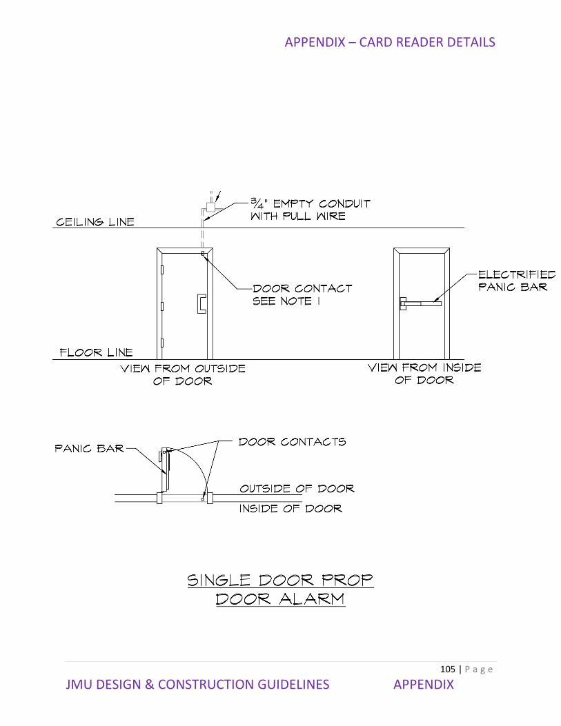
APPENDIX – CARD READER DETAILS
105 | P a g e
JMU DESIGN & CONSTRUCTION GUIDELINES APPENDIX

APPENDIX – CARD READER DETAILS
106 | P a g e
JMU DESIGN & CONSTRUCTION GUIDELINES APPENDIX

APPENDIX – CARD READER DETAILS
107 | P a g e
JMU DESIGN & CONSTRUCTION GUIDELINES APPENDIX

APPENDIX – CARD READER DETAILS
108 | P a g e
JMU DESIGN & CONSTRUCTION GUIDELINES APPENDIX

APPENDIX – CARD READER DETAILS
109 | P a g e
JMU DESIGN & CONSTRUCTION GUIDELINES APPENDIX