Embed Size (px)
Citation preview
Contents lists available at ScienceDirect
Corrosion Science
journal homepage: www.elsevier.com/locate/corsci
Experimental and thermodynamic investigations on the chlorine-inducedcorrosion of HVOF thermal sprayed NiAl coatings and 304 stainless steels at700 °C
Mingwen Bai, Liam Reddy, Tanvir Hussain⁎
Faculty of Engineering, University of Nottingham, NG7 2RD, UK
A R T I C L E I N F O
Keywords:Nickel aluminideStainless steelHVOFBiomassChlorineThermodynamic
A B S T R A C T
Alumina-forming β-NiAl coatings were deposited by high velocity oxy-fuel (HVOF) thermal spraying onto 304stainless steels for protection against chlorine induced corrosion in a biomass-fired boiler. The corrosion test wasconducted in a synthetic gas containing 500 ppm HCl with 10wt% KCl ash deposit at 700 °C for 250 h. Severecorrosion was observed with the fast growing alumina at the coating/substrate interface initiating from sample edges.Possible corrosion mechanism was proposed: as supplied by HCl/KCl, the formation of volatile chlorine/chlorideacted as a catalyst and promoted the growth of alumina at relatively lower application temperatures (<900 °C).
1. Introduction
Biomass fuel is a direct replacement for coal to be utilized in tra-ditional coal-fired power plants without requiring plant operators toinvest in expensive combustion modifications and limited modificationsto handling, and storage facilities. Nevertheless, biomass fuel, such asrecycled wood, straw and agricultural crops, also faces new challengesas it normally contains a high content of alkali metals, chlorine andother corrosive elements [1,2]. It would cause severe high temperaturecorrosion of metallic heat exchanger surfaces, and leads to materialdamage, and shortened lifetime [3]. In addition, a surging demand forhigher energy efficiency and lower CO2 emissions has stimulated therapid development of ultra-supercritical (USC) power plants, where thetemperatures will be in excess of 650 °C (e.g. the European AD700program, the American A-USC (760 °C), and the Japanese A-USC, etc.)[4]. This increasingly harsh environment, however, limits the selectionof materials to high-alloy steels and nickel-based alloys that couldprovide sufficient creep and fireside corrosion resistance [5]. Overlaycorrosion-resistant coatings could also be applied to further improvethe protection against the aggressive fireside corrosion. High-velocityoxy-fuel (HVOF) thermal spraying is one of the most widely usedcoating techniques for the deposition of Cr2O3-forming and Al2O3-forming alloys for high temperature corrosion/oxidation protection[6–8]. Cr2O3-forming alloys (e.g. Fe-Cr and Ni-Cr alloys) are mostwidely sprayed as coatings for corrosion protection [9–14]. However,previous researches have shown that the corrosive alkali chlorides (e.g.KCl) reacts with Cr2O3 in the protective scale to form K2CrO4 [15–18].
Chlorine could penetrate the oxide scale, forming volatile metalchlorides at the scale metal interface. The breakdown of the Cr2O3 scaleaccelerates corrosion attack by subsequently converting to oxides andreleasing the chlorine back to the metal surface [19,20]. Al2O3-formingalloys (e.g. Fe-Al, Ni-Al alloys) has provided a viable alternative ascoatings for high temperature corrosion protection, although the tem-perature lower than 700 °C may not be high enough to obtain a pro-tective scale [21,22]. It has been reported that the addition of Al toFe–Cr alloys is beneficial for the corrosion resistance at 650 °C with KClsalt [23]. An alumina scale formed by pre-oxidation of a FeCrAl alloy at700 °C for 24 h also showed improvement in resistance against attack byKCl at 600 °C [24]. It was also demonstrated that the reaction of KClwith Al2O3 to produce potassium aluminate (KAlO2) is thermo-dynamically less favored than K2CrO4 at the relevant temperature [25].In addition, Li et al. [26] investigated the hot corrosion behaviour ofvarious Fe–Cr, Fe–Al and Ni-Al model alloys in air with NaCl–KCl de-posit at 670 °C for 48 h. In their study, it was found that, among thethree model alloys, the NiAl alloys performed the best corrosion re-sistance with the greatest inertness to chloride salt and the least attackin chlorine-containing environments. The inter-metallic β-NiAl phasecoating has been widely used since the 1960s [27] for the protection ofgas turbines blades at high temperatures up to 1000 °C.
In the study, NiAl coatings were deposited by HVOF thermal sprayonto 304 stainless steels and then subjected to a corrosion test at 700 °C for250 h with ash deposit containing 10wt.% of KCl salt in a synthetic gascontaining 5 vol.% O2, 500 ppm HCl and balance N2. It is worth notingthat other gases, such as H2O, NOx and SOx, etc. were deliberately omitted
https://doi.org/10.1016/j.corsci.2018.02.047Received 6 September 2017; Received in revised form 14 February 2018; Accepted 20 February 2018
⁎ Corresponding author.E-mail address: [email protected] (T. Hussain).
Corrosion Science 135 (2018) 147–157
Available online 21 February 20180010-938X/ © 2018 The Authors. Published by Elsevier Ltd. This is an open access article under the CC BY license (http://creativecommons.org/licenses/BY/4.0/).
T
from the synthetic flue gas in order to create a simplified environment.The main focus is to study the sole effect of KCl/HCl on the corrosionbehaviour of NiAl coatings and stainless steels substrates for the applica-tion of next generation ultra-supercritical biomass-fired boilers. The cor-rosion products were investigated by scanning electron microscopy (SEM),energy dispersive X-ray (EDX) and X-ray diffraction (XRD) analysis, incomparison with the normal oxidation products in air without KCl andHCl. With the intent of providing further insight into the complex corro-sion mechanism that involve both O2 and Cl2, and the subsequent for-mation of the oxides and volatile chlorides, a commercially availablesoftware, Thermo-Calc®, was used to study the equilibrium oxide phasesexisting in the NiAl+O2+Cl2 system at 700 °C. In the end, a possiblecorrosion mechanism was proposed based on the thermodynamic calcu-lations with a focus on the O2 and Cl2 partial pressures.
2. Experimental
2.1. Powder and substrate
A commercial NiAl powder for thermal spraying (AMPERIT291,fused/crushed, H.C.Starck, UK) was used as feedstock with a nominalcomposition of Ni69Al31 wt.% and a particle size distribution of5–45 μm. The NiAl powder was sprayed onto AISI 304 stainless steelssubstrates (nominal composition Fe-19.0Cr- 9.3 Ni- 2.0Mn- 0.05C wt.%)with a dimension of 60×25×2mm.
2.2. HVOF thermal spray process
Substrates were grit blasted with brown alumina (F22, 0.8–1.0 mm)under 6 bar pressure, and cleaned by an ultrasonic acetone bath to re-move any embedded alumina particles. The substrates were mountedonto a carousel rotating at 73 rpm with a vertical axis of rotation.Metjet IV, a liquid fuel based HVOF thermal spray system (MetallisationLtd., UK), was used for thermal spraying of the NiAl coatings withkerosene as the fuel. The coatings were deposited with 16 passes and apowder feed rate of ∼30 g/min, resulting in a thickness of ∼50 μm(deposition efficiency was limited by the low flowability of the feed-stock NiAl powders), and the samples were air-cooled during spraying.The length of the nozzle of the HVOF thermal spray gun was 100mmand a stand-off distance of 356mm was used during the spray runs. Theflow rates of kerosene and oxygen were 415mL/min and 800 L/min,respectively; nitrogen was used a carrier gas for the powder. The di-mensions of the samples for the corrosion tests were 10mm×10mm,same with our previous studies [28,29]. It is worth noting that since thesamples were not fully coated with NiAl coatings, the sample edges mayact as an initiation for the corrosion attack.
2.3. Chlorine-induced corrosion test
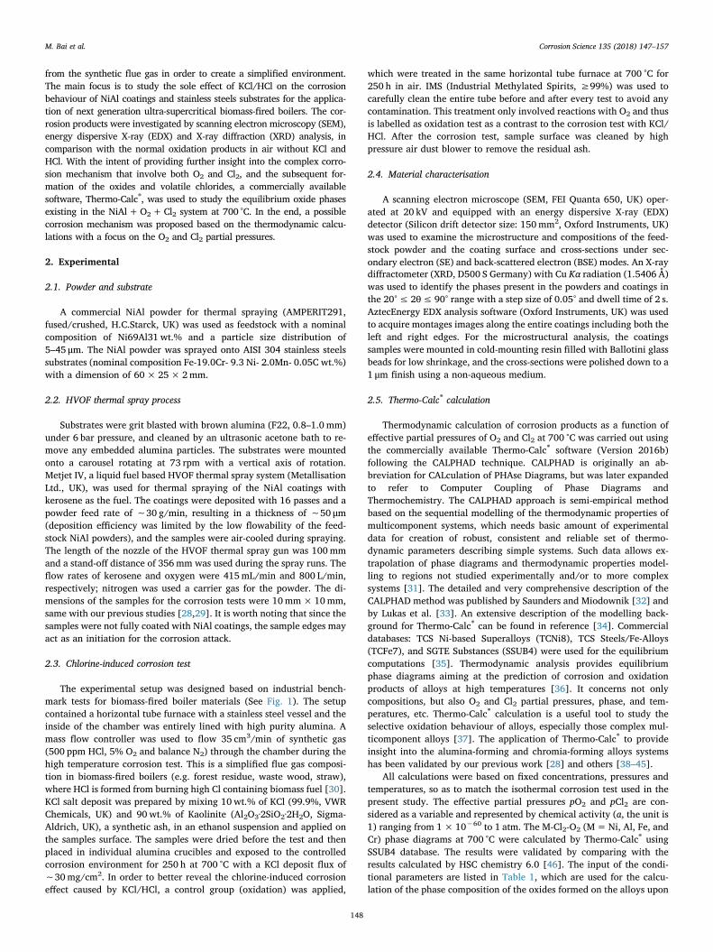
The experimental setup was designed based on industrial bench-mark tests for biomass-fired boiler materials (See Fig. 1). The setupcontained a horizontal tube furnace with a stainless steel vessel and theinside of the chamber was entirely lined with high purity alumina. Amass flow controller was used to flow 35 cm3/min of synthetic gas(500 ppm HCl, 5% O2 and balance N2) through the chamber during thehigh temperature corrosion test. This is a simplified flue gas composi-tion in biomass-fired boilers (e.g. forest residue, waste wood, straw),where HCl is formed from burning high Cl containing biomass fuel [30].KCl salt deposit was prepared by mixing 10wt.% of KCl (99.9%, VWRChemicals, UK) and 90wt.% of Kaolinite (Al2O3·2SiO2·2H2O, Sigma-Aldrich, UK), a synthetic ash, in an ethanol suspension and applied onthe samples surface. The samples were dried before the test and thenplaced in individual alumina crucibles and exposed to the controlledcorrosion environment for 250 h at 700 °C with a KCl deposit flux of∼30mg/cm2. In order to better reveal the chlorine-induced corrosioneffect caused by KCl/HCl, a control group (oxidation) was applied,
which were treated in the same horizontal tube furnace at 700 °C for250 h in air. IMS (Industrial Methylated Spirits, ≥99%) was used tocarefully clean the entire tube before and after every test to avoid anycontamination. This treatment only involved reactions with O2 and thusis labelled as oxidation test as a contrast to the corrosion test with KCl/HCl. After the corrosion test, sample surface was cleaned by highpressure air dust blower to remove the residual ash.
2.4. Material characterisation
A scanning electron microscope (SEM, FEI Quanta 650, UK) oper-ated at 20 kV and equipped with an energy dispersive X-ray (EDX)detector (Silicon drift detector size: 150mm2, Oxford Instruments, UK)was used to examine the microstructure and compositions of the feed-stock powder and the coating surface and cross-sections under sec-ondary electron (SE) and back-scattered electron (BSE) modes. An X-raydiffractometer (XRD, D500 S Germany) with Cu Kα radiation (1.5406 Å)was used to identify the phases present in the powders and coatings inthe 20°≤ 2θ≤ 90° range with a step size of 0.05° and dwell time of 2 s.AztecEnergy EDX analysis software (Oxford Instruments, UK) was usedto acquire montages images along the entire coatings including both theleft and right edges. For the microstructural analysis, the coatingssamples were mounted in cold-mounting resin filled with Ballotini glassbeads for low shrinkage, and the cross-sections were polished down to a1 μm finish using a non-aqueous medium.
2.5. Thermo-Calc® calculation
Thermodynamic calculation of corrosion products as a function ofeffective partial pressures of O2 and Cl2 at 700 °C was carried out usingthe commercially available Thermo-Calc® software (Version 2016b)following the CALPHAD technique. CALPHAD is originally an ab-breviation for CALculation of PHAse Diagrams, but was later expandedto refer to Computer Coupling of Phase Diagrams andThermochemistry. The CALPHAD approach is semi-empirical methodbased on the sequential modelling of the thermodynamic properties ofmulticomponent systems, which needs basic amount of experimentaldata for creation of robust, consistent and reliable set of thermo-dynamic parameters describing simple systems. Such data allows ex-trapolation of phase diagrams and thermodynamic properties model-ling to regions not studied experimentally and/or to more complexsystems [31]. The detailed and very comprehensive description of theCALPHAD method was published by Saunders and Miodownik [32] andby Lukas et al. [33]. An extensive description of the modelling back-ground for Thermo-Calc® can be found in reference [34]. Commercialdatabases: TCS Ni-based Superalloys (TCNi8), TCS Steels/Fe-Alloys(TCFe7), and SGTE Substances (SSUB4) were used for the equilibriumcomputations [35]. Thermodynamic analysis provides equilibriumphase diagrams aiming at the prediction of corrosion and oxidationproducts of alloys at high temperatures [36]. It concerns not onlycompositions, but also O2 and Cl2 partial pressures, phase, and tem-peratures, etc. Thermo-Calc® calculation is a useful tool to study theselective oxidation behaviour of alloys, especially those complex mul-ticomponent alloys [37]. The application of Thermo-Calc® to provideinsight into the alumina-forming and chromia-forming alloys systemshas been validated by our previous work [28] and others [38–45].
All calculations were based on fixed concentrations, pressures andtemperatures, so as to match the isothermal corrosion test used in thepresent study. The effective partial pressures pO2 and pCl2 are con-sidered as a variable and represented by chemical activity (a, the unit is1) ranging from 1×10−60 to 1 atm. The M-Cl2-O2 (M=Ni, Al, Fe, andCr) phase diagrams at 700 °C were calculated by Thermo-Calc® usingSSUB4 database. The results were validated by comparing with theresults calculated by HSC chemistry 6.0 [46]. The input of the condi-tional parameters are listed in Table 1, which are used for the calcu-lation of the phase composition of the oxides formed on the alloys upon
M. Bai et al. Corrosion Science 135 (2018) 147–157
148
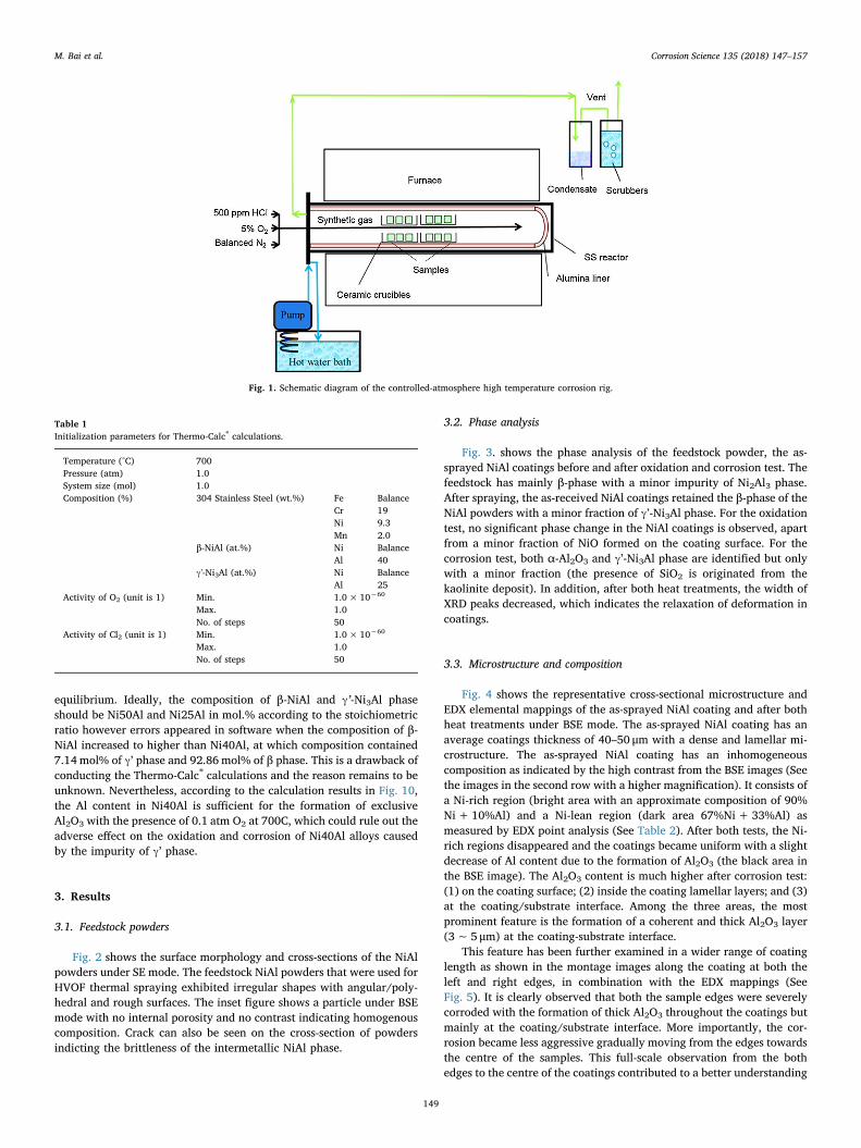
equilibrium. Ideally, the composition of β-NiAl and γ’-Ni3Al phaseshould be Ni50Al and Ni25Al in mol.% according to the stoichiometricratio however errors appeared in software when the composition of β-NiAl increased to higher than Ni40Al, at which composition contained7.14mol% of γ’ phase and 92.86mol% of β phase. This is a drawback ofconducting the Thermo-Calc® calculations and the reason remains to beunknown. Nevertheless, according to the calculation results in Fig. 10,the Al content in Ni40Al is sufficient for the formation of exclusiveAl2O3 with the presence of 0.1 atm O2 at 700C, which could rule out theadverse effect on the oxidation and corrosion of Ni40Al alloys causedby the impurity of γ’ phase.
3. Results
3.1. Feedstock powders
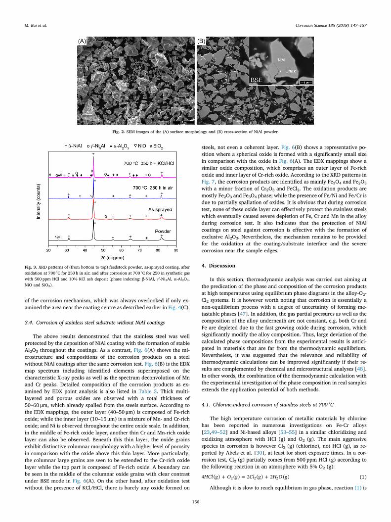
Fig. 2 shows the surface morphology and cross-sections of the NiAlpowders under SE mode. The feedstock NiAl powders that were used forHVOF thermal spraying exhibited irregular shapes with angular/poly-hedral and rough surfaces. The inset figure shows a particle under BSEmode with no internal porosity and no contrast indicating homogenouscomposition. Crack can also be seen on the cross-section of powdersindicting the brittleness of the intermetallic NiAl phase.
3.2. Phase analysis
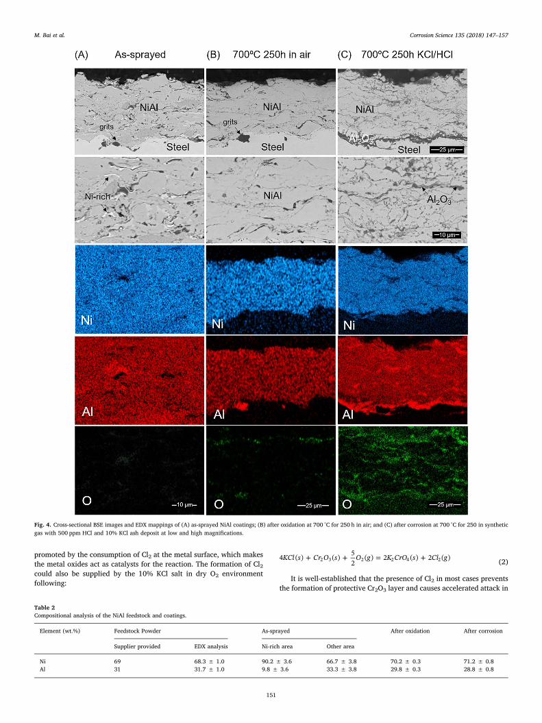
Fig. 3. shows the phase analysis of the feedstock powder, the as-sprayed NiAl coatings before and after oxidation and corrosion test. Thefeedstock has mainly β-phase with a minor impurity of Ni2Al3 phase.After spraying, the as-received NiAl coatings retained the β-phase of theNiAl powders with a minor fraction of γ’-Ni3Al phase. For the oxidationtest, no significant phase change in the NiAl coatings is observed, apartfrom a minor fraction of NiO formed on the coating surface. For thecorrosion test, both α-Al2O3 and γ’-Ni3Al phase are identified but onlywith a minor fraction (the presence of SiO2 is originated from thekaolinite deposit). In addition, after both heat treatments, the width ofXRD peaks decreased, which indicates the relaxation of deformation incoatings.
3.3. Microstructure and composition
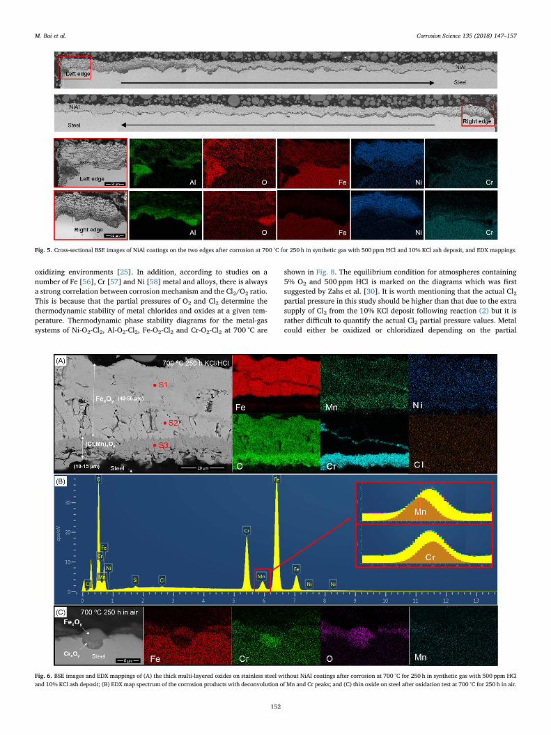
Fig. 4 shows the representative cross-sectional microstructure andEDX elemental mappings of the as-sprayed NiAl coating and after bothheat treatments under BSE mode. The as-sprayed NiAl coating has anaverage coatings thickness of 40–50 μm with a dense and lamellar mi-crostructure. The as-sprayed NiAl coating has an inhomogeneouscomposition as indicated by the high contrast from the BSE images (Seethe images in the second row with a higher magnification). It consists ofa Ni-rich region (bright area with an approximate composition of 90%Ni+10%Al) and a Ni-lean region (dark area 67%Ni+ 33%Al) asmeasured by EDX point analysis (See Table 2). After both tests, the Ni-rich regions disappeared and the coatings became uniform with a slightdecrease of Al content due to the formation of Al2O3 (the black area inthe BSE image). The Al2O3 content is much higher after corrosion test:(1) on the coating surface; (2) inside the coating lamellar layers; and (3)at the coating/substrate interface. Among the three areas, the mostprominent feature is the formation of a coherent and thick Al2O3 layer(3∼ 5 μm) at the coating-substrate interface.
This feature has been further examined in a wider range of coatinglength as shown in the montage images along the coating at both theleft and right edges, in combination with the EDX mappings (SeeFig. 5). It is clearly observed that both the sample edges were severelycorroded with the formation of thick Al2O3 throughout the coatings butmainly at the coating/substrate interface. More importantly, the cor-rosion became less aggressive gradually moving from the edges towardsthe centre of the samples. This full-scale observation from the bothedges to the centre of the coatings contributed to a better understanding
Fig. 1. Schematic diagram of the controlled-atmosphere high temperature corrosion rig.
Table 1Initialization parameters for Thermo-Calc® calculations.
Temperature (°C) 700Pressure (atm) 1.0System size (mol) 1.0Composition (%) 304 Stainless Steel (wt.%) Fe Balance
Cr 19Ni 9.3Mn 2.0
β-NiAl (at.%) Ni BalanceAl 40
γ'-Ni3Al (at.%) Ni BalanceAl 25
Activity of O2 (unit is 1) Min. 1.0× 10−60
Max. 1.0No. of steps 50
Activity of Cl2 (unit is 1) Min. 1.0× 10−60
Max. 1.0No. of steps 50
M. Bai et al. Corrosion Science 135 (2018) 147–157
149
of the corrosion mechanism, which was always overlooked if only ex-amined the area near the coating centre as described earlier in Fig. 4(C).
3.4. Corrosion of stainless steel substrate without NiAl coatings
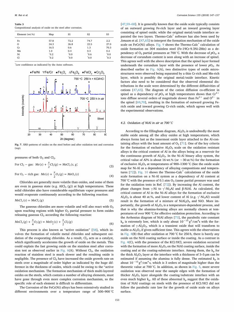
The above results demonstrated that the stainless steel was wellprotected by the deposition of NiAl coating with the formation of stableAl2O3 throughout the coatings. As a contrast, Fig. 6(A) shows the mi-crostructure and compositions of the corrosion products on a steelwithout NiAl coatings after the same corrosion test. Fig. 6(B) is the EDXmap spectrum including identified elements superimposed on thecharacteristic X-ray peaks as well as the spectrum deconvolution of Mnand Cr peaks. Detailed composition of the corrosion products as ex-amined by EDX point analysis is also listed in Table 3. Thick multi-layered and porous oxides are observed with a total thickness of50–60 μm, which already spalled from the steels surface. According tothe EDX mappings, the outer layer (40–50 μm) is composed of Fe-richoxide; while the inner layer (10–15 μm) is a mixture of Mn- and Cr-richoxide; and Ni is observed throughout the entire oxide scale. In addition,in the middle of Fe-rich oxide layer, another thin Cr and Mn-rich oxidelayer can also be observed. Beneath this thin layer, the oxide grainsexhibit distinctive columnar morphology with a higher level of porosityin comparison with the oxide above this thin layer. More particularly,the columnar large grains are seen to be extended to the Cr-rich oxidelayer while the top part is composed of Fe-rich oxide. A boundary canbe seen in the middle of the columnar oxide grains with clear contrastunder BSE mode in Fig. 6(A). On the other hand, after oxidation testwithout the presence of KCl/HCl, there is barely any oxide formed on
steels, not even a coherent layer. Fig. 6(B) shows a representative po-sition where a spherical oxide is formed with a significantly small sizein comparison with the oxide in Fig. 6(A). The EDX mappings show asimilar oxide composition, which comprises an outer layer of Fe-richoxide and inner layer of Cr-rich oxide. According to the XRD patterns inFig. 7, the corrosion products are identified as mainly Fe3O4 and Fe2O3
with a minor fraction of Cr2O3 and FeCl2. The oxidation products aremostly Fe2O3 and Fe3O4 phase; while the presence of Fe/Ni and Fe/Cr isdue to partially spallation of oxides. It is obvious that during corrosiontest, none of these oxide layer can effectively protect the stainless steelswhich eventually caused severe depletion of Fe, Cr and Mn in the alloyduring corrosion test. It also indicates that the protection of NiAlcoatings on steel against corrosion is effective with the formation ofexclusive Al2O3. Nevertheless, the mechanism remains to be providedfor the oxidation at the coating/substrate interface and the severecorrosion near the sample edges.
4. Discussion
In this section, thermodynamic analysis was carried out aiming atthe predication of the phase and composition of the corrosion productsat high temperatures using equilibrium phase diagrams in the alloy-O2-Cl2 systems. It is however worth noting that corrosion is essentially anon-equilibrium process with a degree of uncertainty of forming me-tastable phases [47]. In addition, the gas partial pressures as well as thecomposition of the alloy underneath are not constant, e.g. both Cr andFe are depleted due to the fast growing oxide during corrosion, whichsignificantly modify the alloy composition. Thus, large deviation of thecalculated phase compositions from the experimental results is antici-pated in materials that are far from the thermodynamic equilibrium.Nevertheless, it was suggested that the relevance and reliability ofthermodynamic calculations can be improved significantly if their re-sults are complemented by chemical and microstructural analyses [48].In other words, the combination of the thermodynamic calculation withthe experimental investigation of the phase composition in real samplesextends the application potential of both methods.
4.1. Chlorine-induced corrosion of stainless steels at 700 °C
The high temperature corrosion of metallic materials by chlorinehas been reported in numerous investigations on Fe-Cr alloys[23,49–52] and Ni-based alloys [53–55] in a similar chloridizing andoxidizing atmosphere with HCl (g) and O2 (g). The main aggressivespecies in corrosion is however Cl2 (g) (chlorine), not HCl (g), as re-ported by Abels et al. [30], at least for short exposure times. In a cor-rosion test, Cl2 (g) partially comes from 500 ppm HCl (g) according tothe following reaction in an atmosphere with 5% O2 (g):
+ = +HCl g O g Cl g H O g4 ( ) ( ) 2 ( ) 2 ( )2 2 2 (1)
Although it is slow to reach equilibrium in gas phase, reaction (1) is
Fig. 2. SEM images of the (A) surface morphology and (B) cross-section of NiAl powder.
Fig. 3. XRD patterns of (from bottom to top) feedstock powder, as-sprayed coating, afteroxidation at 700 °C for 250 h in air; and after corrosion at 700 °C for 250 in synthetic gaswith 500 ppm HCl and 10% KCl ash deposit (phase indexing: β-NiAl, γ’-Ni3Al, α-Al2O3,NiO and SiO2).
M. Bai et al. Corrosion Science 135 (2018) 147–157
150
promoted by the consumption of Cl2 at the metal surface, which makesthe metal oxides act as catalysts for the reaction. The formation of Cl2could also be supplied by the 10% KCl salt in dry O2 environmentfollowing:
+ + = +KCl s Cr O s O g K CrO s Cl g4 ( ) ( ) 52
( ) 2 ( ) 2 ( )2 3 2 2 4 2 (2)
It is well-established that the presence of Cl2 in most cases preventsthe formation of protective Cr2O3 layer and causes accelerated attack in
Fig. 4. Cross-sectional BSE images and EDX mappings of (A) as-sprayed NiAl coatings; (B) after oxidation at 700 °C for 250 h in air; and (C) after corrosion at 700 °C for 250 in syntheticgas with 500 ppm HCl and 10% KCl ash deposit at low and high magnifications.
Table 2Compositional analysis of the NiAl feedstock and coatings.
Element (wt.%) Feedstock Powder As-sprayed After oxidation After corrosion
Supplier provided EDX analysis Ni-rich area Other area
Ni 69 68.3 ± 1.0 90.2 ± 3.6 66.7 ± 3.8 70.2 ± 0.3 71.2 ± 0.8Al 31 31.7 ± 1.0 9.8 ± 3.6 33.3 ± 3.8 29.8 ± 0.3 28.8 ± 0.8
M. Bai et al. Corrosion Science 135 (2018) 147–157
151
oxidizing environments [25]. In addition, according to studies on anumber of Fe [56], Cr [57] and Ni [58] metal and alloys, there is alwaysa strong correlation between corrosion mechanism and the Cl2/O2 ratio.This is because that the partial pressures of O2 and Cl2 determine thethermodynamic stability of metal chlorides and oxides at a given tem-perature. Thermodynamic phase stability diagrams for the metal-gassystems of Ni-O2-Cl2, Al-O2-Cl2, Fe-O2-Cl2 and Cr-O2-Cl2 at 700 °C are
shown in Fig. 8. The equilibrium condition for atmospheres containing5% O2 and 500 ppm HCl is marked on the diagrams which was firstsuggested by Zahs et al. [30]. It is worth mentioning that the actual Cl2partial pressure in this study should be higher than that due to the extrasupply of Cl2 from the 10% KCl deposit following reaction (2) but it israther difficult to quantify the actual Cl2 partial pressure values. Metalcould either be oxidized or chloridized depending on the partial
Fig. 5. Cross-sectional BSE images of NiAl coatings on the two edges after corrosion at 700 °C for 250 h in synthetic gas with 500 ppm HCl and 10% KCl ash deposit, and EDX mappings.
Fig. 6. BSE images and EDX mappings of (A) the thick multi-layered oxides on stainless steel without NiAl coatings after corrosion at 700 °C for 250 h in synthetic gas with 500 ppm HCland 10% KCl ash deposit; (B) EDX map spectrum of the corrosion products with deconvolution of Mn and Cr peaks; and (C) thin oxide on steel after oxidation test at 700 °C for 250 h in air.
M. Bai et al. Corrosion Science 135 (2018) 147–157
152
pressures of both O2 and Cl2.
− + =Me s x Cl g MeCl s gFor Cl gas: ( )2
( ) ( , )x2 2 (3)
− + =Me s x O g MeO sFor O rich gas: ( )2
( ) ( )x2 2 (4)
Chlorides are generally more volatile than oxides, and some of themare even in gaseous state (e.g. AlCl3 (g)) at high temperatures. Thesesolid chlorides also have considerable equilibrium vapor pressures andwould evaporate continuously according to the following reaction:
=MeCl s MeCl g( ) ( )x x (5)
The gaseous chlorides are more volatile and will also react with O2
upon reaching regions with higher O2 partial pressure to form oxidesreleasing gaseous Cl2 according the following reaction:
+ = +MeCl g x O g MeO s x Cl g( )4
( ) ( )2
( )x x2 2 2 (6)
This process is also known as “active oxidation” [58], which in-volves the formation of volatile metal chlorides and subsequent oxi-dation of the evaporating chlorides. As a result, Cl2 acts as a catalyst,which significantly accelerates the growth of oxide on the metals. Thiscould explain the fast growing oxide on the stainless steel after corro-sion test as observed earlier in Fig. 6(A). Without Cl2, the oxidationreaction of stainless steel is much slower and the resulting oxide isnegligible. The presence of Cl2 have increased the oxide growth rate onsteels over a magnitude of order higher as indicated by the huge dif-ference in the thickness of oxides, which could be owing to the “activeoxidation mechanism. The formation mechanism of thick multi-layeredoxides on the steels, which contain a number of alloying elements, musthave gone through even more complex corrosion mechanism, so thespecific role of each element is difficult to differentiate.
The Corrosion of the FeCr(Ni) alloys has been extensively studied indifferent environments over a temperature range of 500–900 °C
[47,59–68]. It is generally known that the oxide scale typically consistsof an outward growing Fe-rich layer and an inward growing layerconsisting of spinel oxide; while the original metal/oxide interface se-parated the two layers. Thermo-Calc® software has also been used byJonsson et al. [47,65] to interpret the formation mechanism of the oxidescale on FeCr(Ni) alloys. Fig. 9 shows the Thermo-Calc® calculation ofoxide formation on 304 stainless steel (Fe-19Cr-9.3Ni-2Mn) as a de-pendency of O2 partial pressures at 700 °C. With the decrease of pO2, adecrease of corundum content is seen along with an increase of spinel.This agrees well with the above description that the spinel layer formedunderneath the corundum layer with the presence of lower pO2. Asdescribed earlier in Fig. 6(A), two distinctive types of oxide micro-structures were observed being separated by a thin Cr-rich and Mn-richlayer, which is possibly the original metal/oxide interface. Kineticfactors also need to be considered that the observed elemental dis-tributions in the scale were determined by the different diffusivities ofcations [47,65]. The diagram of the cation diffusion co-efficient inspinel as a dependency of pO2 at high temperatures shows that Cr3+
ions diffuse several orders of magnitude slower than Fe2+ and O2− inthe spinel [69,70], resulting in the formation of outward growing Fe-rich oxide and inward growing Cr-rich oxide, which agrees well withthe experimental observations.
4.2. Oxidation of NiAl in air at 700 °C
According to the Ellingham diagram, Al2O3 is undoubtedly the moststable oxide among all the alloy oxides at high temperatures, whichalways forms last as the innermost oxide layer attached to the Al-con-taining alloys with the least amount of O2 [71]. One of the key criteriafor the formation of exclusive Al2O3 scale on the oxidation resistantalloys is the critical content of Al in the alloys being as a reservoir forthe continuous growth of Al2O3. In the Ni-Al binary alloy system, thecritical value of Al% is about 16 wt.% (or ∼30 at.%) for the formationof exclusive Al2O3 at temperatures of 900–1300 °C (See the oxide scalemap for Ni-Al as a dependency of alloying compositions and tempera-tures [72]). Fig. 10 shows the Thermo-Calc® calculations of the oxidescale formation on a Ni-Al system as a dependency of Al content at700 °C with the presence of 0.1 atm O2 (same partial pressure was usedfor the oxidation tests in Ref. [72]). By increasing the Al content, thephase changes from γ-Ni to γ’-Ni3Al and β-NiAl. As calculated, thecritical content of Al in the Ni-Al alloys for the formation of exclusiveAl2O3 is about 40 at.%, and lower content of Al (e.g. γ’-Ni3Al) wouldresult in the formation of a mixture of NiAl2O4 and NiO. More im-portantly, the growth of Al2O3 is a temperature-dependent process, andthat is why the alumina-forming alloys are normally chosen at tem-peratures of over 900 °C for effective oxidation protection. According tothe Arrhenius diagram of NiAl alloys [73], the parabolic rate constantkp is extremely low, which is only about 10−15 g2/cm4s with the for-mation of γ-Al2O3, which is a transient oxide that will transform tostable α-Al2O3 if given sufficient time. This agrees with the observationsin Fig. 4(B) that after oxidation at 700 °C for 250 h, there is barely anyoxide on the NiAl coating surface or inside the coating. As a contrast inFig. 4(C), with the presence of the KCl/HCl, severe oxidation occurredwith the formation of more Al2O3 on the NiAl coating surface, inside thecoating and at the coating-substrate interface. Among them, the kp forthe thick Al2O3 layer at the interface with a thickness of 3–5 μm can beestimated if assuming the alumina is fully dense. The estimated kp isabout 10−12 g2/cm4 s, which is 3 orders of magnitude higher than thetheoretic value at 700 °C. In addition, as shown in Fig. 5, more severeoxidation was observed near the sample edges with the formation ofthicker Al2O3 layer alongside the coating/substrate interface with aneven much higher kp. All of these abnormal kp suggest that the oxida-tion of NiAl coatings on steels with the presence of KCl/HCl did notfollow the parabolic rate law for the growth of oxide scale on alloyssurface.
Table 3Compositional analysis of oxide on the steel after corrosion.
Element (wt.%) Map S1 S2 S3
Fe 57.8 72.2 74.7 2.2O 24.3 26.8 22.5 27.0Cr 16.5 0.6 1.3 70.3Mn 1.0 0.4 0.3 0.2Ni *0.2 *0.0 *0.6 *0.0Cl *0.2 *0.0 *0.0 *0.3
*Low confidence as indicated by the Aztec software.
Fig. 7. XRD patterns of oxides on the steel before and after oxidation test and corrosion(top).
M. Bai et al. Corrosion Science 135 (2018) 147–157
153
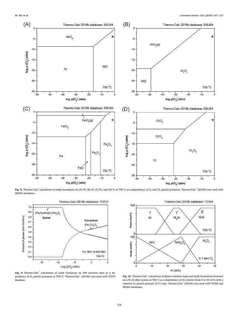
Fig. 8. Thermo-Calc® calculation of oxide formations on (A) Ni; (B) Al; (C) Fe; and (D) Cr at 700 °C as a dependency of O2 and Cl2 partial pressures. Thermo-Calc® (2016b) was used withSSUB4 databases.
Fig. 9. Thermo-Calc® calculation of oxide formation on 304 stainless steel as a de-pendency of O2 partial pressures at 700 °C. Thermo-Calc® (2016b) was used with TCFe7database.
Fig. 10. Thermo-Calc® calculation of phase evolution (top) and oxide formations (bottom)on a Ni-Al alloy system at 700 °C as a dependency of Al content (from 0 to 50 at%) with aconstant O2 partial pressure of 0.1 atm. Thermo-Calc® (2016b) was used with TCNi8 andSSUB4 databases.
M. Bai et al. Corrosion Science 135 (2018) 147–157
154
4.3. Phase stability of NiAl-Cl2-O2 system at 700 °C
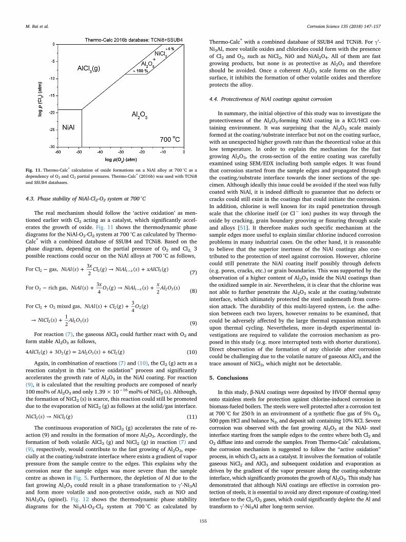
The real mechanism should follow the ‘active oxidation’ as men-tioned earlier with Cl2 acting as a catalyst, which significantly accel-erates the growth of oxide. Fig. 11 shows the thermodynamic phasediagrams for the NiAl-O2-Cl2 system at 700 °C as calculated by Thermo-Calc® with a combined database of SSUB4 and TCNi8. Based on thephase diagram, depending on the partial pressure of O2 and Cl2, 3possible reactions could occur on the NiAl alloys at 700 °C as follows,
− + → +−NiAl s x Cl g NiAl s xAlCl gFor Cl gas, ( ) 32
( ) ( ) ( )x2 2 1 3 (7)
− + → +−NiAl s x O g NiAl s x Al O sFor O rich gas, ( ) 34
( ) ( )2
( )x2 2 1 2 3 (8)
+ + +
→ +
NiAl s Cl g O g
NiCl s Al O s
For Cl O mixed gas, ( ) ( ) 34
( )
( ) 12
( )
2 2 2 2
2 2 3 (9)
For reaction (7), the gaseous AlCl3 could further react with O2 andform stable Al2O3 as follows,
+ = +AlCl g O g Al O s Cl g4 ( ) 3 ( ) 2 ( ) 6 ( )3 2 2 3 2 (10)
Again, in combination of reactions (7) and (10), the Cl2 (g) acts as areaction catalyst in this “active oxidation” process and significantlyaccelerates the growth rate of Al2O3 in the NiAl coating. For reaction(9), it is calculated that the resulting products are composed of nearly100mol% of Al2O3 and only 1.39×10⁻¹⁶ mol% of NiCl2 (s). Although,the formation of NiCl2 (s) is scarce, this reaction could still be promoteddue to the evaporation of NiCl2 (g) as follows at the solid/gas interface.
→NiCl s NiCl g( ) ( )2 2 (11)
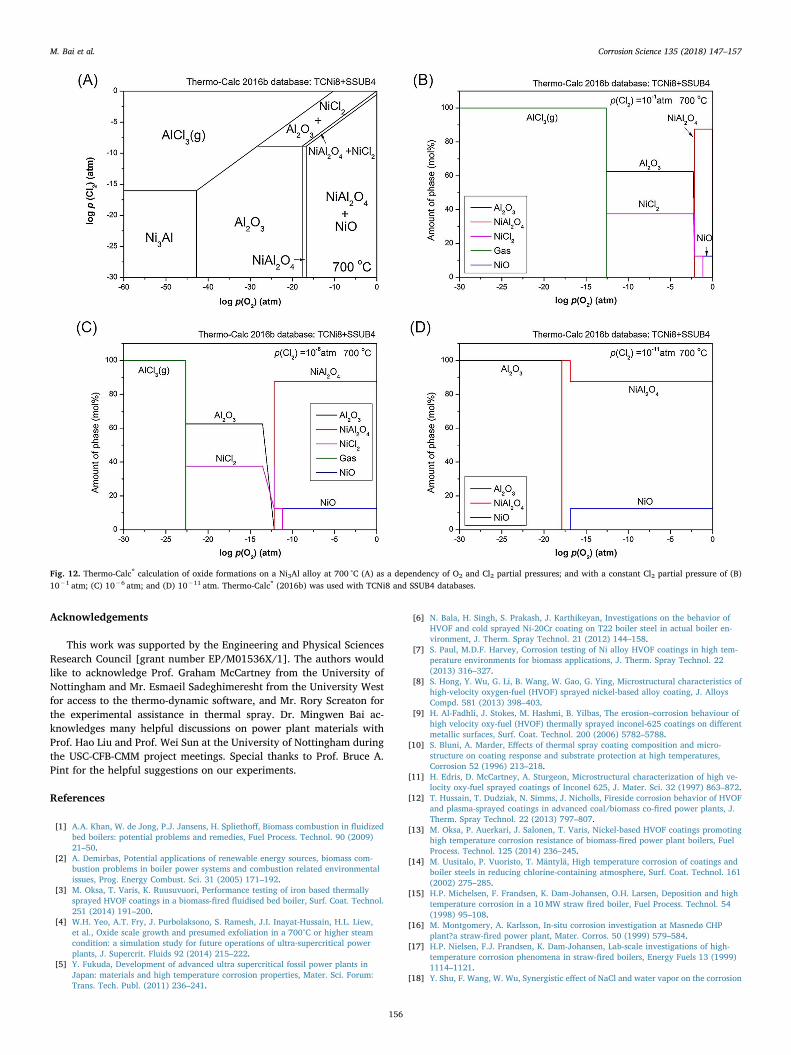
The continuous evaporation of NiCl2 (g) accelerates the rate of re-action (9) and results in the formation of more Al2O3. Accordingly, theformation of both volatile AlCl3 (g) and NiCl2 (g) in reaction (7) and(9), respectively, would contribute to the fast growing of Al2O3, espe-cially at the coating/substrate interface where exists a gradient of vaporpressure from the sample centre to the edges. This explains why thecorrosion near the sample edges was more severe than the samplecentre as shown in Fig. 5. Furthermore, the depletion of Al due to thefast growing Al2O3 could result in a phase transformation to γ’-Ni3Aland form more volatile and non-protective oxide, such as NiO andNiAl2O4 (spinel). Fig. 12 shows the thermodynamic phase stabilitydiagrams for the Ni3Al-O2-Cl2 system at 700 °C as calculated by
Thermo-Calc® with a combined database of SSUB4 and TCNi8. For γ’-Ni3Al, more volatile oxides and chlorides could form with the presenceof Cl2 and O2, such as NiCl2, NiO and NiAl2O4. All of them are fastgrowing products, but none is as protective as Al2O3 and thereforeshould be avoided. Once a coherent Al2O3 scale forms on the alloysurface, it inhibits the formation of other volatile oxides and thereforeprotects the alloy.
4.4. Protectiveness of NiAl coatings against corrosion
In summary, the initial objective of this study was to investigate theprotectiveness of the Al2O3-forming NiAl coating in a KCl/HCl con-taining environment. It was surprising that the Al2O3 scale mainlyformed at the coating/substrate interface but not on the coating surface,with an unexpected higher growth rate than the theoretical value at thislow temperature. In order to explain the mechanism for the fastgrowing Al2O3, the cross-section of the entire coating was carefullyexamined using SEM/EDX including both sample edges. It was foundthat corrosion started from the sample edges and propagated throughthe coating/substrate interface towards the inner sections of the spe-cimen. Although ideally this issue could be avoided if the steel was fullycoated with NiAl, it is indeed difficult to guarantee that no defects orcracks could still exist in the coatings that could initiate the corrosion.In addition, chlorine is well known for its rapid penetration throughscale that the chlorine itself (or Cl− ion) pushes its way through theoxide by cracking, grain boundary grooving or fissuring through scaleand alloys [51]. It therefore makes such specific mechanism at thesample edges more useful to explain similar chlorine induced corrosionproblems in many industrial cases. On the other hand, it is reasonableto believe that the superior inertness of the NiAl coatings also con-tributed to the protection of steel against corrosion. However, chlorinecould still penetrate the NiAl coating itself possibly through defects(e.g. pores, cracks, etc.) or grain boundaries. This was supported by theobservation of a higher content of Al2O3 inside the NiAl coatings thanthe oxidized sample in air. Nevertheless, it is clear that the chlorine wasnot able to further penetrate the Al2O3 scale at the coating/substrateinterface, which ultimately protected the steel underneath from corro-sion attack. The durability of this multi-layered system, i.e. the adhe-sion between each two layers, however remains to be examined, thatcould be adversely affected by the large thermal expansion mismatchupon thermal cycling. Nevertheless, more in-depth experimental in-vestigations are required to validate the corrosion mechanism as pro-posed in this study (e.g. more interrupted tests with shorter durations).Direct observation of the formation of any chloride after corrosioncould be challenging due to the volatile nature of gaseous AlCl3 and thetrace amount of NiCl2, which might not be detectable.
5. Conclusions
In this study, β-NiAl coatings were deposited by HVOF thermal sprayonto stainless steels for protection against chlorine-induced corrosion inbiomass-fueled boilers. The steels were well protected after a corrosion testat 700 °C for 250 h in an environment of a synthetic flue gas of 5% O2,500 ppm HCl and balance N2, and deposit salt containing 10% KCl. Severecorrosion was observed with the fast growing Al2O3 at the NiAl- steelinterface starting from the sample edges to the centre where both Cl2 andO2 diffuse into and corrode the samples. From Thermo-Calc® calculations,the corrosion mechanism is suggested to follow the “active oxidation”process, in which Cl2 acts as a catalyst. It involves the formation of volatilegaseous NiCl2 and AlCl3 and subsequent oxidation and evaporation asdriven by the gradient of the vapor pressure along the coating-substrateinterface, which significantly promotes the growth of Al2O3. This study hasdemonstrated that although NiAl coatings are effective in corrosion pro-tection of steels, it is essential to avoid any direct exposure of coating/steelinterface to the Cl2/O2 gases, which could significantly deplete the Al andtransform to γ’-Ni3Al after long-term service.
Fig. 11. Thermo-Calc® calculation of oxide formations on a NiAl alloy at 700 °C as adependency of O2 and Cl2 partial pressures. Thermo-Calc® (2016b) was used with TCNi8and SSUB4 databases.
M. Bai et al. Corrosion Science 135 (2018) 147–157
155
Acknowledgements
This work was supported by the Engineering and Physical SciencesResearch Council [grant number EP/M01536X/1]. The authors wouldlike to acknowledge Prof. Graham McCartney from the University ofNottingham and Mr. Esmaeil Sadeghimeresht from the University Westfor access to the thermo-dynamic software, and Mr. Rory Screaton forthe experimental assistance in thermal spray. Dr. Mingwen Bai ac-knowledges many helpful discussions on power plant materials withProf. Hao Liu and Prof. Wei Sun at the University of Nottingham duringthe USC-CFB-CMM project meetings. Special thanks to Prof. Bruce A.Pint for the helpful suggestions on our experiments.
References
[1] A.A. Khan, W. de Jong, P.J. Jansens, H. Spliethoff, Biomass combustion in fluidizedbed boilers: potential problems and remedies, Fuel Process. Technol. 90 (2009)21–50.
[2] A. Demirbas, Potential applications of renewable energy sources, biomass com-bustion problems in boiler power systems and combustion related environmentalissues, Prog. Energy Combust. Sci. 31 (2005) 171–192.
[3] M. Oksa, T. Varis, K. Ruusuvuori, Performance testing of iron based thermallysprayed HVOF coatings in a biomass-fired fluidised bed boiler, Surf. Coat. Technol.251 (2014) 191–200.
[4] W.H. Yeo, A.T. Fry, J. Purbolaksono, S. Ramesh, J.I. Inayat-Hussain, H.L. Liew,et al., Oxide scale growth and presumed exfoliation in a 700°C or higher steamcondition: a simulation study for future operations of ultra-supercritical powerplants, J. Supercrit. Fluids 92 (2014) 215–222.
[5] Y. Fukuda, Development of advanced ultra supercritical fossil power plants inJapan: materials and high temperature corrosion properties, Mater. Sci. Forum:Trans. Tech. Publ. (2011) 236–241.
[6] N. Bala, H. Singh, S. Prakash, J. Karthikeyan, Investigations on the behavior ofHVOF and cold sprayed Ni-20Cr coating on T22 boiler steel in actual boiler en-vironment, J. Therm. Spray Technol. 21 (2012) 144–158.
[7] S. Paul, M.D.F. Harvey, Corrosion testing of Ni alloy HVOF coatings in high tem-perature environments for biomass applications, J. Therm. Spray Technol. 22(2013) 316–327.
[8] S. Hong, Y. Wu, G. Li, B. Wang, W. Gao, G. Ying, Microstructural characteristics ofhigh-velocity oxygen-fuel (HVOF) sprayed nickel-based alloy coating, J. AlloysCompd. 581 (2013) 398–403.
[9] H. Al-Fadhli, J. Stokes, M. Hashmi, B. Yilbas, The erosion–corrosion behaviour ofhigh velocity oxy-fuel (HVOF) thermally sprayed inconel-625 coatings on differentmetallic surfaces, Surf. Coat. Technol. 200 (2006) 5782–5788.
[10] S. Bluni, A. Marder, Effects of thermal spray coating composition and micro-structure on coating response and substrate protection at high temperatures,Corrosion 52 (1996) 213–218.
[11] H. Edris, D. McCartney, A. Sturgeon, Microstructural characterization of high ve-locity oxy-fuel sprayed coatings of Inconel 625, J. Mater. Sci. 32 (1997) 863–872.
[12] T. Hussain, T. Dudziak, N. Simms, J. Nicholls, Fireside corrosion behavior of HVOFand plasma-sprayed coatings in advanced coal/biomass co-fired power plants, J.Therm. Spray Technol. 22 (2013) 797–807.
[13] M. Oksa, P. Auerkari, J. Salonen, T. Varis, Nickel-based HVOF coatings promotinghigh temperature corrosion resistance of biomass-fired power plant boilers, FuelProcess. Technol. 125 (2014) 236–245.
[14] M. Uusitalo, P. Vuoristo, T. Mäntylä, High temperature corrosion of coatings andboiler steels in reducing chlorine-containing atmosphere, Surf. Coat. Technol. 161(2002) 275–285.
[15] H.P. Michelsen, F. Frandsen, K. Dam-Johansen, O.H. Larsen, Deposition and hightemperature corrosion in a 10MW straw fired boiler, Fuel Process. Technol. 54(1998) 95–108.
[16] M. Montgomery, A. Karlsson, In‐situ corrosion investigation at Masnedø CHPplant?a straw‐fired power plant, Mater. Corros. 50 (1999) 579–584.
[17] H.P. Nielsen, F.J. Frandsen, K. Dam-Johansen, Lab-scale investigations of high-temperature corrosion phenomena in straw-fired boilers, Energy Fuels 13 (1999)1114–1121.
[18] Y. Shu, F. Wang, W. Wu, Synergistic effect of NaCl and water vapor on the corrosion
Fig. 12. Thermo-Calc® calculation of oxide formations on a Ni3Al alloy at 700 °C (A) as a dependency of O2 and Cl2 partial pressures; and with a constant Cl2 partial pressure of (B)10−1 atm; (C) 10−6 atm; and (D) 10−11 atm. Thermo-Calc® (2016b) was used with TCNi8 and SSUB4 databases.
M. Bai et al. Corrosion Science 135 (2018) 147–157
156
of 1Cr-11Ni-2W-2Mo-V steel at 500–700C, Oxid. Metals 51 (1999) 97–110.[19] C. Pettersson, J. Pettersson, H. Asteman, J.E. Svensson, L.G. Johansson, KCl-induced
high temperature corrosion of the austenitic Fe–Cr–Ni alloys 304L and Sanicro 28 at600°C, Corros. Sci. 48 (2006) 1368–1378.
[20] J. Pettersson, N. Folkeson, L.-G. Johansson, J.-E. Svensson, The effects of KCl,K2SO4 and K2CO3 on the high temperature corrosion of a 304-type austeniticstainless steel, Oxid. Metals 76 (2011) 93–109.
[21] H. Asteman, M. Spiegel, A comparison of the oxidation behaviours of Al 2 O 3formers and Cr 2 O 3 formers at 700 C–oxide solid solutions acting as a template fornucleation, Corros. Sci. 50 (2008) 1734–1743.
[22] H. Josefsson, F. Liu, J.E. Svensson, M. Halvarsson, L.G. Johansson, Oxidation ofFeCrAl alloys at 500–900C in dry O2, Mater. Corros. 56 (2005) 801–805.
[23] Y.S. Li, Y. Niu, M. Spiegel, High temperature interaction of Al/Si-modified Fe-Cralloys with KCl, Corros. Sci. 49 (2007) 1799–1815.
[24] N. Israelsson, J. Engkvist, K. Hellström, M. Halvarsson, J.-E. Svensson, L.-G. Johansson, KCl-induced corrosion of an FeCrAl alloy at 600C in O2+ H2O en-vironment: the effect of pre-oxidation, Oxid. Metals 83 (2015) 29–53.
[25] N. Israelsson, K.A. Unocic, K. Hellstrom, T. Jonsson, M. Norell, J.E. Svensson, et al.,A microstructural and kinetic investigation of the KCl-induced corrosion of anFeCrAl alloy at 600°C, Oxid. Metals 84 (2015) 105–127.
[26] Y. Li, M. Spiegel, S. Shimada, Corrosion behaviour of various model alloys withNaCl?KCl coating, Mater. Chem. Phys. 93 (2005) 217–223.
[27] J. Nicholls, Advances in coating design for high-performance gas turbines, MRSBull. 28 (2003) 659–670.
[28] Z. Pala, M. Bai, F. Lukac, T. Hussain, Laser clad and HVOF-sprayed stellite 6 coatingin chlorine-rich environment with KCl at 700°C, Oxid. Metals 88 (2017) 749–771.
[29] L. Reddy, P. Shipway, C. Davis, T. Hussain, HVOF and laser-cladded Fe–Cr–Bcoating in simulated biomass combustion: microstructure and fireside corrosion,Oxid. Metals 87 (2017) 825–835.
[30] A. Zahs, M. Spiegel, H.J. Grabke, Chloridation and oxidation of iron, chromium,nickel and their alloys in chloridizing and oxidizing atmospheres at 400–700C,Corros. Sci. 42 (2000) 1093–1122.
[31] A. Kroupa, Modelling of phase diagrams and thermodynamic properties usingCalphad method −development of thermodynamic databases, Comput. Mater. Sci66 (2013) 3–13.
[32] N. Saunders, A.P. Miodownik, CALPHAD (calculation of Phase Diagrams): aComprehensive Guide, Elsevier, 1998.
[33] H.L. Lukas, S.G. Fries, B. Sundman, Computational Thermodynamics: the CalphadMethod, Cambridge University Press, Cambridge, 2007.
[34] J.O. Andersson, T. Helander, L. Höglund, P. Shi, B. Sundman, Thermo-Calc &DICTRA, computational tools for materials science, Calphad 26 (2002) 273–312.
[35] J. Bratberg, H. Mao, L. Kjellqvist, A. Engström, P. Mason, Q. Chen, The developmentand validation of a new thermodynamic database for Ni-based alloys, Superalloys12 (2012) 803–812.
[36] B. Gorr, H.-J. Christ, D. Mukherji, J. Rösler, Thermodynamic calculations in thedevelopment of high-temperature Co–Re-based alloys, J. Alloys Compd. 582 (2014)50–58.
[37] O. Bergman, Influence of oxygen partial pressure in sintering atmosphere onproperties of Cr–Mo prealloyed powder metallurgy steel, Powder Metall. 50 (2007)243–249.
[38] T.J. Nijdam, W.G. Sloof, Microstructural evolution of a MCrAlY coating upon iso-thermal annealing, Mater. Charact. 59 (2008) 1697–1704.
[39] K. Ma, J.M. Schoenung, Thermodynamic investigation into the equilibrium phasesin the NiCoCrAl system at elevated temperatures, Surf. Coat. Technol. 205 (2010)2273–2280.
[40] K. Ma, F. Tang, J.M. Schoenung, Investigation into the effects of Fe additions on theequilibrium phase compositions, phase fractions and phase stabilities in theNi–Cr–Al system, Acta Mater. 58 (2010) 1518–1529.
[41] J. Liang, H. Wei, Y. Zhu, T. Jin, X. Sun, Z. Hu, Phase stabilities in a NiCrAlYRecoating alloy, Surf. Coat. Technol. 206 (2012) 2746–2750.
[42] J. Liang, H. Wei, Y. Zhu, X. Sun, Z. Hu, M. Dargusch, et al., Phase constituents andthermal expansion behavior of a NiCrAlYRe coating alloy, J. Mater. Sci. 46 (2011)500–508.
[43] B. Baufeld, M. Schmücker, Microstructural evolution of a NiCoCrAlY coating on anIN100 substrate, Surf. Coat. Technol. 199 (2005) 49–56.
[44] D.R.G. Achar, R. Munoz-Arroyo, L. Singheiser, W.J. Quadakkers, Modelling of phaseequilibria in MCrAlY coating systems, Surf. Coat. Technol. 187 (2004) 272–283.
[45] L.T. Wu, R.T. Wu, P. Xiao, T. Osada, K.I. Lee, M. Bai, A prominent driving force forthe spallation of thermal barrier coatings: chemistry dependent phase transforma-tion of the bond coat, Acta Mater. 137 (2017) 22–35.
[46] A. Roine, HSC Chemistry, Outokumpu Research Oy, Pori, Finland, 2002.[47] T. Jonsson, H. Larsson, S. Karlsson, H. Hooshyar, M. Sattari, J. Liske, et al., High-
temperature oxidation of FeCr (Ni) alloys: the behaviour after Breakaway, Oxid.Metals 87 (2017) 333–341.
[48] M. Born, J. Korb, D. Rafaja, M. Dopita, R.W. Schülein, Capability of thermodynamiccalculation in the development of alloys for deposition of corrosion-protectioncoatings via thermal spraying, Mater. Corros. 58 (2007) 673–680.
[49] X. Zheng, R.A. Rapp, Chloridation-oxidation of nine commercial high-temperaturealloys at 800°C, Oxid. Metals 48 (1997) 553–596.
[50] A. Kim, M. McNallan, Mixed Oxidation of Iron–Chromium Alloys in GasesContaining Oxygen and Chlorine at 900–1200°K, Corrosion 46 (1990) 746–755.
[51] H.J. Grabke, E. Reese, M. Spiegel, The effects of chlorides, hydrogen-chloride, andsulfur-dioxide in the oxidation of steels below deposits, Corros. Sci. 37 (1995)1023–1043.
[52] M. Spiegel, C. Schroer, H.J. Grabke, Corrosion of high alloy steels and Fe-Cr-alloysbeneath deposits from waste incinerator plants, Mater. Sci. Forum: Trans. Tech.Publ. (1997) 527–534.
[53] J.-M. Abels, H.-H. Strehblow, A surface analytical approach to the high temperaturechlorination behaviour of inconel 600 at 700C, Corros. Sci. 39 (1997) 115–132.
[54] H. Chu, P. Datta, K. Strafford, Corrosion behavior of Fe (Ni) CrAIX alloys in an HCl-h 2 O- H 2 gas mixture at 800°C, Oxid. Metals 43 (1995) 491–508.
[55] R. Prescott, F. Stott, P. Elliott, Investigations of the degradation of high-temperaturealloys in a potentially oxidizing-chloridizing gas mixture, Oxid. Metals 31 (1989)145–166.
[56] K. Strafford, P. Datta, G. Forster, High-temperature chloridation of binary Fe Cralloys at 1000°C, Mater. Sci. Eng. A 120 (1989) 61–68.
[57] Y. Shinata, M. Hara, T. Nakagawa, Accelerated oxidation of chromium by trace ofsodium chloride vapor, Mater. Trans. JIM 32 (1991) 969–972.
[58] Y. Lee, M. McNallan, Ignition of nickel in environments containing oxygen andchlorine, Metall. Mater. Trans. A 18 (1987) 1099–1107.
[59] T. Jonsson, F. Liu, S. Canovic, H. Asteman, J.-E. Svensson, L.-G. Johansson, et al.,Influence of H2O (g) on the oxide microstructure of the stainless steel 353MA at900°C in oxygen, J. Electrochem. Soc. 154 (2007) C603–C610.
[60] T. Jonsson, J. Froitzheim, J. Pettersson, J.-E. Svensson, L.-G. Johansson,M. Halvarsson, The influence of KCl on the corrosion of an austenitic stainless steel(304L) in oxidizing humid conditions at 600C: a microstructural study, Oxid. Metals72 (2009) 213–239.
[61] T. Jonsson, N. Folkeson, J.-E. Svensson, L.-G. Johansson, M. Halvarsson, An ESEMin situ investigation of initial stages of the KCl induced high temperature corrosionof a Fe–2. 25 Cr–1Mo steel at 400C, Corros. Sci. 53 (2011) 2233–2246.
[62] B. Pujilaksono, T. Jonsson, H. Heidari, M. Halvarsson, J.-E. Svensson, L.-G. Johansson, Oxidation of binary FeCr alloys (Fe–2. 25 Cr, Fe–10Cr, Fe–18Cr andFe–25Cr) in O2 and in O2+ H2O environment at 600C, Oxid. Metals 75 (2011)183–207.
[63] T. Jonsson, B. Pujilaksono, H. Heidari, F. Liu, J.-E. Svensson, M. Halvarsson, et al.,Oxidation of Fe–10Cr in o 2 and in o 2+ H 2 O environment at 600C: a micro-structural investigation, Corros. Sci. 75 (2013) 326–336.
[64] T. Jonsson, N. Folkeson, M. Halvarsson, J.-E. Svensson, L.-G. Johansson,Microstructural investigation of the HCl-induced corrosion of the austenitic alloy310S (52Fe26Cr19Ni) at 500C, Oxid. Metals 81 (2014) 575–596.
[65] T. Jonsson, S. Karlsson, H. Hooshyar, M. Sattari, J. Liske, J.-E. Svensson, et al.,Oxidation after breakdown of the chromium-rich scale on stainless steels at hightemperature: internal oxidation, Oxid. Metals 85 (2016) 509–536.
[66] M. Halvarsson, J.E. Tang, H. Asteman, J.-E. Svensson, L.-G. Johansson,Microstructural investigation of the breakdown of the protective oxide scale on a304 steel in the presence of oxygen and water vapour at 600C, Corros. Sci. 48(2006) 2014–2035.
[67] G.H. Meier, K. Jung, N. Mu, N.M. Yanar, F.S. Pettit, J. Pirón Abellán, et al., Effect ofalloy composition and exposure conditions on the selective oxidation behavior offerritic Fe–Cr and Fe–Cr–X alloys, Oxid. Metals 74 (2010) 319–340.
[68] H. Hooshyar, T. Jonsson, J. Hall, J.-E. Svensson, L. Johansson, J. Liske, The effect ofH2 and H2O on the oxidation of 304L-stainless steel at 600°C: general behaviour(part I), Oxid. Metals 85 (2016) 321–342.
[69] J.A. Van Orman, K.L. Crispin, Diffusion in oxides, Rev. Mineral. Geochem. 72(2010) 757–825.
[70] J. Töpfer, S. Aggarwal, R. Dieckmann, Point defects and cation tracer diffusion in(CrxFe1- x) 3- δO4 spinels, Solid State Ionics 81 (1995) 251–266.
[71] J.A. Nychka, D.R. Clarke, G.H. Meier, Spallation and transient oxide growth onPWA 1484 superalloy, Mater. Sci. Eng. A 490 (2008) 359–368.
[72] B. Gleeson, N. Mu, S. Hayashi, Compositional factors affecting the establishmentand maintenance of Al2O3 scales on Ni–Al–Pt systems, J. Mater. Sci. 44 (2009)1704–1710.
[73] H. Grabke, Oxidation of NiAl and FeAl, Intermetallics 7 (1999) 1153–1158.
M. Bai et al. Corrosion Science 135 (2018) 147–157
157