Embed Size (px)
Citation preview

1
THERMODYNAMIC INVESTIGATIONS OF ZEOTROPIC MIXTURE OF R290, R23 & R14
ON THREE STAGE AUTO REFRIGERATING CASCADE SYSTEM
* SIVAKUMAR.M, P. SOMASUDARAM
* Assistant Professor, KPR Institute of Engineering and Technology, Coimbatore, Tamilnadu, India.
e-mail: [email protected] Mobile: +91-9865843427
Professor and Head, Department of Mechanical Engineering, Erode Builders Educational Trust’s
Group of Institutions, Kangeyam, Tamilnadu, India. e-mail: [email protected]
Abstract:
The Zeotropic mixture of environment friendly refrigerants (HC’s and HFC’s) being the
only alternatives for working fluid in low temperature refrigeration system and hence three
stage Auto Refrigerating Cascade (ARC) system was studied for the existence using 4
combinations of three component Zeotropic mixture of six different refrigerants. The exergy
analysis confirmed the existence of three stage ARC system. The performances of the
system like Coefficient of Performance (COP), exergy lost, exergic efficiency, efficiency
defect and the evaporating temperature achieved were investigated for different mass
fractions in order to verify the effect of mass fraction on them. In accordance with the
environmental issues and the process of sustainable development, the three component
Zeotropic mixture of R290/R23/R14 with the mass fraction of 0.218:0.346:0.436 was
performing better and hence can be suggested as an alternative refrigerant for three stage
ARC system operating at very low evaporating temperature in the range of -970C (176K) at
COP of 0.253 and comparatively increased exergic efficiency up to 16.3% (58.5%).
Keywords:
Zeotropic mixture of R290/R23/R14, 3 stage ARC, COP, efficiency defect, exergy analysis and exergic
efficiency
List of Symbols
: Exergy flow (J kg-1
)
x : Exergy Efficiency (%)
: Efficiency Defect
COP : Coefficient of performance
h : Specific Enthalpy (J kg-1
)
T0 : Ambient temperature (K)
Tevaporator-I,II,III : Evaporating temperature of cascade condenser-I,II,III
[Refirigerant-1,II,III] in (K)
TACC, condenser-I,II : Condensing temperature [Refrigerant-I,II,III] in (K)

2
s : Specific Entropy (J kg-1
K-1
)
Wc : Compressor work input (W)
m : Mass (Total Refrigerant) flow rate ( RIIIRIIRI mmm
m ) (kg s-1
)
mRI,RII,RIII : Mass Flow rate of Refrigerant I,II,III (kg s-1
)
QACC,condenser-I, II,
evaporator-III,II,I
: Heat removed at Air cooled condenser, condenser-I,II,
evaporator-III,II,I] (W)
I Total, comp, ACC, condenser-I,II,
TEV-I, II,III,evaporator-I,II,III
: Exergy loss in (J s-1
)
Subscripts
evaporator-I : Evaporator - I RII : Refrigerant – II
evaporator-II : Evaporator - II RIII : Refrigerant - III
evaporator-III : Evaporator - III Total : Total System
condenser-I : Condenser - I comp : Compressor
condenser-II : Condenser - II TEV-I : Thermostatic Expansion Valve-I
ACC : Air Cooled Condenser TEV-II : Thermostatic Expansion Valve-II
RI Refrigerant - I TEV-III Thermostatic Expansion Valve-III
1,2, ... 15 : State Points of the system
1. Introduction
Ozone level in the Arctic region as was measured as 320 DU (Dobson units) or about 150
DU below spring time as normal as of 450DU in 1956 at first as an unknown phenomenon of Ozone
Hole by G.M.B Dobson. But the CFC’s lead the world of Refrigeration industries for over 6 decades
before the harmful effect on the Ozone layer was identified in 1974 by Frank Sherwood Rowland and
his postdoctoral associate Mario J. Molina.
Since exergic efficiency is higher in the case of system being charged 100%, COP is
highest at 50% charging and refrigerating effect is highest at 25% charging, anand et al. [1] suggested
the system to be operated at optimum balance between refrigerating effect and energy savings.
Ciro Aprea et al. [2] have studied COP improvement by employing pressure control at
gas-cooler outlet and quantified as 6.6–8.5% under minimum pressure working condition at different
Tambient.
Cleland et al. [3] have quantified the system performances and stated that the system with
mixture of propane and ethane (Care-50) reduced energy use by 6–8% under similar system cooling
capacity relative to HCFC-22. With propane (Care-40) the energy use decreased by 5% but cooling
capacity was 9% lower.
Dave Sajjan et al. [4] have investigated the performance of the system of R22 with the
retrofit of R407C. The experimental and theoretical investigation confirmed the drop in shell-and-tube
condenser performance and quantified that the reduction in performance can be as large as 70% when
compared to the full condenser load.
Dongoo Jung et al. [5] have examined the performance of R290 / R600a mixture of mass
fraction 0.6 : 0.4 in domestic refrigerators and suggested the COP increase of 2.3%. Three to four

3
Percentage (3-4%) of higher energy efficiency at faster cooling rate as well as shorter compressor on-
time and lower compressor dome temperatures were confirmed with this mixture compared to R12.
Eric lemmon et al. [6] have reported that no additional parameters were required to model
the ternary mixture and also slight systematic offsets were seen in several locations for example, The
R-32/125/134a system is unique from a modelling standpoint since it combines the three mixture
equations, the individual equations for R-32/125, R-32/134a and the generalized equation for R-
125/134a.
Jianyong Chen et al. [7] have confirmed the new refrigeration cycle having the evaporator
circuit of two branches to realize lorentz cycle with the advantage of temperature glide (NRC) using
the binary non-azeotropic refrigerant mixture (R32/R134a) which results in 8 to 9% COP raise and
9.5% increase in volumetric refrigerating capacity.
Jianfeng Wu et al. [8] achieved a minimum no-load temperature of -197.70C (about 75.7
K), -1740C (about 99 K) was obtained at 110 W cooling capacities with the mixed-gases
refrigeration using dual mixed-gases Joule Thomson refrigeration system. They achieved the lowest
temperature of -1920C (about 81 K) with an effective preservation volume of 80 L at a relatively
faster cooling-down rate in cryogenic chamber and found 2.5 hours to reach -1800C and 5 hours to
reach -1900C.
Johansson et al. [9] have found the charged composition and the circulated composition as
well as the leak compositions differ. The differed compositions will not affect the cycle performance
using the Zeotropic mixtures like 407C. They have also suggested the predictive model to determine
the circulating composition and suggested that this will be same for Zeotropic mixtures consisting
three or more components.
Kai Du et al. [10] have suggested the use of Zeotropic mixture of R134a & R23 of quality
0.7:0.3 as an alternate working fluid for Auto Cascade Refrigerating system to obtain high COP.
They have also suggested that the raising of mass flux of high boiling liquid refrigerant and reducing
the low boiling liquid refrigerant without any alteration in its discharge condition.
Lecompte et al. [11] found that the usage of mixtures results in an improvement of second
law efficiency between 7.1% and 14.2% when compared to pure working fluids. The source of this
improvement lies in a combination of a higher heat input and higher heat conversion efficiency and is
mainly ascribed to decreased irreversibility in the condenser.
Sivakumar et al. [12,13 & 14] have suggested that the usage of three component Zeotropic
mixture of environment friendly refrigerant mixtures work well within the three stage ARC system
reaching the lowest temperature of 176K (-970C).
Atashafrooz et al. [15] used and conformed the usage of 2-D Cartesian for solving
equations of conservation of mass, momentum and energy with good consistency and
acceptance of system parameters dealing with entropy generation.
Monsef et al. [16] have investigated the bubble pump with five horizontal tubes in
low capacity absorption system of 2.5 kW capacity having submergence ratio 0.4. They
confirmed the better performance in low capacity absorption refrigeration system.
Mani et al. [17] have developed mathematical models using design of experiments
techniques and investigated the vapour compression refrigeration system. The mixture R290
and R600a of mass fraction 0.68:0.32 showed 10.7-23.6% higher coefficient of performance

4
than that with R12 and R134a. They confirmed the effective usage of hydrocarbon mixtures
as an alternate for vapour compression refrigeration system.
Wei Fan et al. [18] have found that the mixture of CO2 and dimethylether having
suppressed flammability and explosive nature works efficiently as a refrigerant for heat
pumps with a large heat-sink temperature rise. They found that the mixture of CO2 /
dimethylether of mass fractions 0.28:0.72 & 0.03:0.97 can be used under conventional
condensation pressure conditions and for space heating applications.
Even though the studies revealed many truth, these studies does not deal with ARC and its
existence with respect to 3 component Zeotropic mixture. So this study is the stepping stone for the
future in Cryo-technologies.
2. Experimental setup and procedure
Three stage Auto Refrigerating cascade system was fabricated as per the design
parameters. The detailed photographic view of the system is shown in Figure1 and the line diagram
of the setup is shown in Figure 2. The compressor used in this system is Kirloskar KCJ450LAL-
B320. A four row air cooled condenser of 2TR capacity is used to facilitate the proper condensing
area. An oil separator was connected to separate the oil from the compressor discharge and the
separated oil was directed to the compressor doom through the suction line of the compressor.
A Non Return Valve (NRV) is being used to avoid the back flow of the liquid refrigerant
and ensuring the oil return into the compressor doom. Filter drier is also used in the system after air
cooled condenser for proper filtration and block free working of the system.
Since the pressure may go up to 700psig during operation and 450psig while system gets
thermal equilibrium with atmosphere, a thick cylinder has been considered for phase separation. To
ensure the proper working of the three stage ARC system, an extruded copper tube of 3mm thickness
with 1.5 feet and another of 1 foot height welded at top and bottom by 4mm thick copper plate were
considered for phase separator I & phase separator-II. Each separator is provided with one input line
which penetrates until the bottom of the phase separator from the top. One more copper line at the top
of the separator provides the high pressure line for the medium and low boiling refrigerants. The
perfect utilization of the liquid refrigerant has been ensured by welding an output line right from the
bottom of the phase separator. Combination of all three lines and the separator ensures perfect
separation of liquid refrigerant through gravity separation.
The air cooled condenser must remove all the heat of refrigerants combined together and
must condense the high boiling refrigerant which is the largest mass fraction of all three circulating
refrigerants. In turn it cools the medium boiling refrigerant and then the medium boiling refrigerant
must cool the low boiling refrigerant to realize the circuit being working continuously. For the
realization of these different requirements of each stage this three stage ARC system considered the
TES2:068Z3403 with orifice sizes of “1”, “0” and “0X” decreasing continuously in size to
accommodate the variation in cooling load.
The setup has one tap with hand shut off valve attached at the free end which can be
extended using 0.013” capillary of 3m length from suction line. Another tap from high pressure line
using 1/4" line with hand shut off valve attached at the free end which inturn can be connected
through a “T” joint with the capillary and further with the provided extra volume in the low pressure

5
side of the system. In case of the system pressure being large during thermal equilibrium with
atmosphere after switching off, these two extensions can be used as by pass line for equalizing the
high and low pressure side of three stage ARC system before starting the compressor.
1- Evaporator tank with Insulating Lid 12- Discharge Line tap with Hand Shut off Valve
2- By pass line with T connection 13- Suction Line tap with Hand Shut off Valve
3- Thermostatic Expansion Valve--II 14- Pressure Chamber
4- Phase Separator-I 15- Cascade Condenser -II
5- Filter Drier 16- Control Unit with Display Unit
6- Thermostatic Expansion Valve--I 17- Thermostatic Expansion Valve-III
7- Discharge Line Hand Shut off Valve 18- Phase Separator-II
8- Suction Line Hand Shut off Valve 19- Extra Volume
9- Outdoor Unit with Condenser Fan 20- Non Return Valve for RIII
10- Cascade Condenser -I 21- Non Return Valve for RII
11- Charging Line 22- Non Return Valve for RI
Fig. 1. Photographic View of Three Stage Auto Refrigerating Cascade (3 stage ARC) System

6
1-Low Pressure Vapour of RI,II&III 2-High Pressure - Superheated Vapour of RI,II&III
3-Sub cooled Liquid of RI+ Superheated Vapour of RII&III 4-Super Heater Vapour of RII&III
5-Sub cooled Liquid of RII+ Superheated Vapour of RIII 6-Super Heater Vapour of RIII
7-Sub cooled Liquid of RIII 8-Sub cooled Liquid of RI
9-Wet Mixture of RI 10-Super Heater Vapour of RI
11-Sub cooled Liquid of RII 12-Wet Mixture of RII
13-Super Heater Vapour of RII 14-Super Heater Vapour of RIII
15-Wet Mixture of RIII
Flow path of refrigerant -I in the circuit is 1-2-3-8-9-10-1
Flow path of refrigerant -II in the circuit is 1-2-3-4-5-11-12-13-1
Flow path of refrigerant -III in the circuit is 1-2-3-4-5-6-7-15-14-1
Fig. 2. Line Diagram of Three Stage Auto Refrigerating Cascade (3 stage ARC) System

7
The capillary will be useful in slow and study suction during start up of the compressor
without any sudden loading of the compressor while the discharge tap valve being closed from the
extra volume. The system is provided with one more tap with hand shutoff valve at the free end which
will be very useful in the case of refrigerant charging while system is working continuously with its
operation.
Cascade condenser-I and cascade condenser-II are used as counter flow heat exchangers
for the better and efficient heat transfer performance between the refrigerants flowing in the circuit.
Since the heat rejected by the low boiling refrigerant must be equal to the heat gained by the medium
boiling refrigerant at Cascade condenser-II, heat rejected by the mixture of medium and low boiling
refrigerants should be equal to heat gained by the high boiling refrigerant in cascade condenser-I.
Cascade condensers were insulated with 100mm thick PUF around them by a bounding box. Flow of
hot fluid inside the inner tube ensures the heat transferred to the cold fluid flowing in outer tube of
cascade condenser in both the cases.
A pressure chamber is used to provide extra volume as well as mixing chamber at suction
side of the system through three different non return valves from evaporator-I [outlet of cascade
condenser-I’s outer tube (cold fluid-high boiling refrigerant)], evaporator-II [outlet of cascade
condenser-II’s outer tube (cold fluid-medium boiling refrigerant)]and evaporator-III [low boiling
refrigerant]. This ensures that the problem of high, medium and low boiling refrigerants influencing
on pressure build-up on each other during operation is resolved.
Outdoor unit of the system is provided with two hand shut off valves at both the ends
along its line for refrigerant isolation and retrieval of refrigerants in case of any alteration work and
trials.
The system was equipped with two number of wattmeter to indicate the power
consumption of the compressor and the heat load given to the evaporator. The heater was connected
through On-off control.
Twelve SZ-7505-P type RTD sensors with an accuracy of 1C & around 13 Mars DTI-
204 type 3 wire RTD sensors with 1C were connected at different positions as stated by the state
points of the system. A total of six number of WIKA 213.53.63 [0-100Kg/cm2 (0-1400psi)] pressure
gauges were used in this system for continuous monitoring of system pressure at suction and
discharge side. The readings confirm that no considerable variation along the length of the piping. So
it was decided to use individual suction pressure for each refrigerant after each expansion, similarly
discharge pressure at the end of the high pressure line of low boiling refrigerant, which travels greater
distance from the compressor [just before TEV-III]. Thermo wells were set for mounting the
temperature sensors with ethylene glycol and water mixture of 0.5:0.5 ratios. This being a slow and
time consuming process, the sensors were set directly on the copper piping as like the bulb of the
thermostatic expansion valves ensuring fast and instant response of the temperature sensors.
A heater was used to provide load to the evaporator. A stirrer was also used to enhance the
heat transfer in the secondary fluid in the evaporator tank. Evaporator tank was insulated with
150mm PUF insulation around it. The perfect insulation is being ensured inside the evaporator tank.
The total heat leak in the setup was less than 5% of the total evaporator load.

8
2.1 REFRIGERANT CHARGING
The ARC system was subjected to leak test with nitrogen at 460 psig. The system was kept
idle for 60 hours and checked for pressure drop to ensure zero leak. Then the system was evacuated to
the vacuum level. After completing the evacuation test, the system was ready for charging the
refrigerant mixture. Initially low boiling refrigerant was charged through charging valve followed by
medium boiling refrigerant and then by the low boiling refrigerant as per the thermodynamically
correct mass fraction. A digital mass balance was used to have accurate mass of charged quantity.
2.2 TESTING METHODOLOGY
After charging the mixture with desired mass fraction, the system was started with uniform
ambient temperature. Before starting the system, pressures at discharge side and suction side were
equalized by the use of the bypass line and extra volume to ensure less starting torque of the
compressor. After the starting of compressor the valve was closed. Different observations like
temperatures at each state point, pressures at each state point, power consumption of compressor and
evaporator heat load were recorded. All the observations were made after getting the equilibrium
condition of the system. The equilibrium state was arrived by adjusting the heater load and evaporator
refrigerating effect. The unchanged temperature of secondary medium ensured this equilibrium state.
The total mass of the refrigerant mixture and mass fraction of mixture was varied and the
performance was recorded. This procedure was repeated for different mass fractions. All the
parameters of the system and mainly the power consumption were observed after the system has
reached the study state condition. Values obtained were used for this study and the characteristic
curves were plotted and the performance of ARC system was studied.
2.3 HEAT LEAK TEST
The heat leak test was carried out to find heat infiltration into the evaporator tank from
ambient temperature and different secondary fluid temperatures. Initially the temperature of secondary
fluid in the evaporator tank was brought down and then the system was stopped. Then the time taken
for every one-degree increment of secondary fluid temperature was recorded.
The non return valve connected at the end of the evaporator coil ensured no influence of
back flow of refrigerant that would heat the secondary fluid. The heat infiltration was calculated using
the following Equation.
Calorimeter Heat Gain = (m. Cp. T) / t
where, m is total mass of secondary fluid in the evaporator tank (kg)
Cp is specific heat of secondary fluid (kJ kg-1 K-1)
T is difference of initial and final temperature (ºC)
t is time taken for T increase of temperature (seconds)
The calculated amount of evaporator heat infiltration for particular secondary fluid
temperature was added to the load indicated in the wattmeter. Hence the exact load on evaporator was
estimated.
3. Exergy Analysis
This investigation performs an exergy analysis to make all exergy losses visible in the
process under study. The method is very powerful when comparing two or more solutions in an
9
objective and quantitative manner. Exergy analysis is especially useful in the design phase and during
optimisation of new processes in terms of exact location for improvement by giving the best clues
where to start, namely at the point where the largest exergy losses appear but does not give direct
answers on how to improve the efficiency of the process. Under the assumption that the change of
kinetic and potential energy is negligible and the ambient temperature is T0 , the exergy is given by
the equations:
sh T 0
(1)
ssThh 000
(2)
For the Three stage Auto Refrigerating Cascade system the component wise the exergy
balance equation can be written as follows
(a) For Compressor:
The exergy loss (due to irreversibility) in the compressor
sThwsThI mmccomp 202101
(3)
(b) For Air cooled Condenser:
The exergy loss (due to irreversibility) in the Air cooled condenser
TTQsThsThI
ACCACCACC
mm 0
3032021 (4)
(c) For Condenser-I (Cascade Condenser-I: Hot fluid flow):
The exergy loss (due to irreversibility) in the condenser-1
sThmsThmI RIIIRIIRIIIRIIIcondenser 505404
T
TQIcondenser
Icondenser
01 (5)
(d) For Condenser-II (Cascade Condenser-II: Hot fluid flow):
The exergy loss (due to irreversibility) in the condenser-II
sThmsThmI RIIIRIIIIIcondenser 707606
T
TQIIcondenser
IIcondenser
01 (6)
(e) For Thermostatic Expansion Valve-I:
The exergy loss (due to irreversibility) in the Thermostatic Expansion valve-I
ssTmI RIITEV 890
(7)
(f) For Thermostatic Expansion Valve-II:
The exergy loss (due to irreversibility) in the Thermostatic Expansion valve-I
ssTmI RIIIITEV 11120
(8)
(g) For Thermostatic Expansion Valve-III:
The exergy loss (due to irreversibility) in the Thermostatic Expansion valve-I

10
ssTmI RIIIIIITEV 7150
(9)
(h) For Evaporator-III:
The exergy loss (due to irreversibility) in the Evaporator-III
TTQsThmI
IIIevaporatorIIIevaporatorRIIIIIIevaporator
0
150151
sThmRIII 14014
(10)
(i) For Evaporator-II (Cascade Condenser-II: Cold Fluid Flow):
The exergy loss (due to irreversibility) in the Evaporator-II
TTQsThmI
IIevaporatorIIevaporatorRIIIIevaporator
0
120121
sThmRII 13013
(11)
(j) For Evaporator-I (Cascade Condenser-I: Cold Fluid Flow):
The exergy loss (due to irreversibility) in the Evaporator-I
TTQsThmI
IevaporatorIevaporatorRIIevaporator
0
9091
sThmRI 10010
(12)
The total Exergy loss of the system is given by the correlation
IIIIII IevaporatorIIcondenserIcondenserACCcompTotal
IIIII IIITEVIITEVITEVIIIevaporatorIIevaporator
(13)
The exergy efficiency is given by
w
TTQ
w c
IIIevaporatorIIIevaporator
cx
0
141
1
(14)
For the Three stage Auto Refrigerating Cascade system the component wise efficiency
defect (i) considering the ratio of exergy used in the corresponding component (i) to the exergy
required to sustain the process (exergy through the compressor, wc).
wc
i
i
(15)
The overall performance of the 3 stage ARC System is determined by evaluating its COP
and is calculated as the ratio between the refrigerating capacity (Q evaporator-III) and the electrical power
supplied to the compressor (wc).
w
Q
c
IIIevaporatorCOP
(16)
11
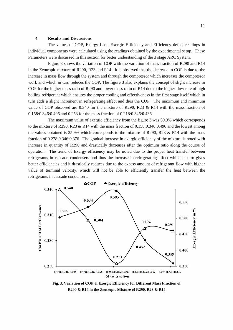
4. Results and Discussions
The values of COP, Exergy Lost, Exergic Efficiency and Efficiency defect readings in
individual components were calculated using the readings obtained by the experimental setup. These
Parameters were discussed in this section for better understanding of the 3 stage ARC System.
Figure 3 shows the variation of COP with the variation of mass fraction of R290 and R14
in the Zeotropic mixture of R290, R23 and R14. It is observed that the decrease in COP is due to the
increase in mass flow through the system and through the compressor which increases the compressor
work and which in turn reduces the COP. The figure 3 also explains the concept of slight increase in
COP for the higher mass ratio of R290 and lower mass ratio of R14 due to the higher flow rate of high
boiling refrigerant which ensures the proper cooling and effectiveness in the first stage itself which in
turn adds a slight increment in refrigerating effect and thus the COP. The maximum and minimum
value of COP observed are 0.340 for the mixture of R290, R23 & R14 with the mass fraction of
0.158:0.346:0.496 and 0.253 for the mass fraction of 0.218:0.346:0.436.
The maximum value of exergic efficiency from the figure 3 was 50.3% which corresponds
to the mixture of R290, R23 & R14 with the mass fraction of 0.158:0.346:0.496 and the lowest among
the values obtained is 35.9% which corresponds to the mixture of R290, R23 & R14 with the mass
fraction of 0.278:0.346:0.376. The gradual increase in exergic efficiency of the mixture is noted with
increase in quantity of R290 and drastically decreases after the optimum ratio along the course of
operation. The trend of Exergy efficiency may be noted due to the proper heat transfer between
refrigerants in cascade condensers and thus the increase in refrigerating effect which in turn gives
better efficiencies and it drastically reduces due to the excess amount of refrigerant flow with higher
value of terminal velocity, which will not be able to efficiently transfer the heat between the
refrigerants in cascade condensers.
Fig. 3. Variation of COP & Exergic Efficiency for Different Mass Fraction of
R290 & R14 in the Zeotropic Mixture of R290, R23 & R14

12
Figure 4 shows the variation of evaporating temperatures and COP achieved using the
Zeotropic Mixture, during different trials with the variation of mass fractions of R290, R23 & R14.
The Lower most evaporating temperature achieved is 176K (-970C) which corresponds to the mixture
of R290, R23 & R14 with the mass fraction of 0.218:0.346:0.436 with COP of 0.253 and the
evaporating temperature achieved is 186K (-870C) which correspond the mass fraction
0.158:0.346:0.496 and 0.278:0.346:0.376 with COPs 0.503 and 0.359.
Even though the COP is higher in case of mass fraction trials 0.158:0.346:0.496,
0.188:0.346:0.466, 0.248:0.346:0.406 and 0.278:0.346:0.376, the evaporating temperatures achieved
during these trials are higher. So the interpretations of this work can lean towards the Lesser COP
with lower Evaporating Temperature trials. Hence the interpretations of this work can lean towards
the lesser COP with lower evaporating temperature trials.
Fig. 4.Variation of COP & Evaporating Temperature for Different Mass Fraction of
R290 & R14 in the Zeotropic Mixture of R290, R23 & R14
Figure 5 shows the variation of evaporating temperature and refrigerating effect with the
variation of mass fraction of R290 and R14 in the Zeotropic Mixture of R290, R23 and R14. Even
though the higher mass flow of high boiling refrigerant enable sufficient cooling for medium and low
boiling refrigerant in condenser -1, the decreased mass flow rate of the low boiling refrigerant at
evaporator-3 with higher terminal velocity reduces the refrigerating effect at lower evaporating
temperatures. The higher values of refrigerating effect is due to the increased mass flow of low
boiling refrigerant assisting with less amount of compressor work and thus the higher COP. The
higher and lower values of refrigerating effect achieved during the trials are 71.2 W and 50.54 W

13
which correspond to the Zeotropic mixtures of mass fractions 0.158:0.346:0.496 and
0.278:0.346:0.376.
Figure 5 interprets the highest value of refrigerating effect and its corresponding higher
evaporating temperature which is not desirable in case of refrigerating cycle. So the optimum
solution should be between the lowest evaporating temperature and optimum refrigerating effect.
Fig. 5. Variation of Evaporating Temperature & Refrigerating Effect for Different
Mass Fraction of R290 & R14 in the Zeotropic Mixture of R290, R23 & R14
Figure 6 shows the variation of compressor work input with the variation of mass fraction
of R290 and R14 in the Zeotropic Mixture of R290, R23 and R14. The maximum and minimum
values of these trials are 209.65 W and 173.44 W corresponds to the mixtures of mass fractions
0.158:0.346:0.496 and 0.278:0.346:0.376. The trend of reduction of compressor work after the
optimum increase in mass flow of high boiling refrigerant is reached, it is observed during the trials
due to the reduced mass flow of low boiling high density refrigerant which has greater influence on
compressor work has better COP due to the increased mass flow of high boiling refrigerant which can
be easily compressed and thus the compressor work reduces.
As the compressor work should be minimum at lowest evaporating temperatures, the
figure 6 does not suggest the trial 5 with mass fraction 0.278:0.346:0.376. So it can be interpreted
that the optimum between evaporating temperature and compressor work.

14
Fig. 6. Variation of Evaporating Temperature & Compressor Work Input
for Different Mass Fraction of R290 & R14 in the Zeotropic Mixture of R290, R23 & R14
Figure 7 shows the variation of compressor work and exergy lost at compressor with
the variation of mass fraction of R290 and R14 in the Zeotropic Mixture of R290, R23 and R14. The
maximum and minimum values of exergy lost at compressor are 143.43 W and 209.65 W which
corresponds to the mixture of mass fraction 0.158:0.346:0.496 having the value of 155.9 W of
compressor work input and 0.278:0.346:0.376 having the value of 173.44 W of compressor work
input. It is evident that whenever the temperature difference between the two state points is high, the
exergy lost (Change in entropy is also high which in turn the exergy or less availability) is also high.
Even though high compressor work leads to lesser COP and low compressor work to
higher COP through the linear variation of exergy loss, this system performs little different due to the
mixing of low boiling high density and high boiling low density refrigerants which will increase the
COP at both the cases. The optimum of compressor work and exergy lost can be the solution.
Fig. 7. Variation of Compressor Work Input & Exergy Lost in Compressor for Different
Mass Fraction of R290 & R14 in the Zeotropic Mixture of R290, R23 & R14

15
Figure 8 shows the variation of evaporating temperatures achieved using the Zeotropic
mixture during the different trials with the variation of mass fractions of R290, R23 & R14. The
lower most evaporating temperature achieved is 176K (-970C) which corresponds to the mixture of
R290, R23 & R14 with the mass fraction of 0.218:0.346:0.436 and the evaporating temperature
achieved is 186K (-870C) which corresponds with the mass fraction 0.158:0.346:0.496 and
0.278:0.346:0.376. The trend of increase in evaporating temperature was due to increased mass flow
of low boiling refrigerant for the trials 4 and 5. The increase in evaporating temperature was due to
the insufficient mass flow of high boiling refrigerant which should cool the medium and low boiling
refrigerants during trials 1 and 2.
Fig. 8. Variation of Evaporating Temperature for Different Mass Fraction of
R290 & R14 in the Zeotropic Mixture of R290, R23 & R14
Figure 9 shows the variation of efficiency defect in each component of the ARC system
with the variation of mass fraction of R290 and R14 in the Zeotropic mixture of R290, R23 and R14.
The maximum and minimum exergy defect are found at compressor (0.68, 0.73, 0.74, 0.69 and 0.65
correspond to trials 1, 2, 3, 4 and 5) and at evaporator 2 (0.02, 0.00, 0.00, 0.02 and 0.02 correspond to
trials 1, 2, 3, 4 and 5).
The phenomenon of increase in efficiency defect is observed due to greater losses in
compressor during trials 1, 2 and 3 with increased mass flow of high boiling refrigerant which has the
tendency to be easily compressed and the excess energy available creates excess temperature
difference and thus the exergy loss and also the efficiency defect. On the other hand the excess
amount of work input during the trials 4 and 5 with the mass fraction of 0.248:0.346:0.406 and
0.278:0.346:0.376 are utilized to compress the low boiling high density refrigerants which make sure

16
less amount of temperature raise during operation and thus the lesser exergy losses when compared to
the trials of 1, 2 and 3 in each and every component.
Fig. 9. Variation of Efficiency Defect in Each Component of ARC System for Different
Mass Fraction of R290 & R14 in the Zeotropic Mixture of R290, R23 & R14
The figures 1 to 9 interprets that the three stage Auto Refrigerating Cascade system is
efficient in dealing with the low temperature at the range of 176K (-970C) with the area of
improvement or concentration should be on the compressor in the aspect of exergy loss and
performance improvement of any Auto Refrigerating Cascade (ARC) System.
5. Conclusions
Exergic analysis and performance analysis of three stage ARC system was conducted on the
setup operating either between the evaporation and condensation temperatures of 176K (-970C) and
301K (300C) or over the temperature range of 187
0C. With reference to the exergic and experimental
study of the system the following conclusions were made.
The Zeotropic mixture of R290 / R23 / R14 with the mass fraction of 0.218:0.346:0.436
having COP of 0.253 & 58.5% of Exergic Efficiency was recommended as an alternative
refrigerant for Three stage ARC system working at the temperature range of 176K (-970C).
The overall efficiency defect is found to be at the range of 65 and 75 for the mixture of
R290 / R23 / R14 with the mass fraction of 0.218:0.346:0.436.
The highest Efficiency defect was found to be at compressor and thus area of improvement
lies in Compressor. Following is the order of components which has larger efficiency defect.
They are Compressor TEV’s and Condensers.
17
The highest exergic efficiency was found to be 58.5% for the Zeotropic mixture of
R290 / R23 / R14 with the mass fraction of 0.218:0.346:0.436 operating at the temperature range
of 176K (-970C).
In general the The Zeotropic Mixture of R290 / R23 / R14 with the mass fraction of
0.218:0.346:0.436 having COP of 0.253 & 58.5% of exergic efficiency was working well in the
three stage ARC system.
Thus it can be concluded that the Zeotropic mixture of R290 / R23 / R14 with the mass
fraction 0.218:0.346:0.436 as an alternative refrigerant for three stage ARC system with slight
modification of the system.
6. References
[1] Anand,S., Tyagi,S.K., Exergy analysis and experimental study of a vapour compression
refrigeration cycle, Journal of Thermal Analysis and Calorimetry, 110 (2012), pp. 961-971.
[2] Ciro Aprea., Angelo Maiorino., Heat rejection pressure optimization for a carbon dioxide split
system: An experimental study, Applied Energy, 86 (2009), pp. 2373-2380.
[3] Cleland,D.J., et.al., Use of hydrocarbons as drop-in Replacements for HCFC-22 in on-farm
Milk Cooling Equipment, International Journal of Refrigeration, 32 (2009), pp. 1403-1411.
[4] Dave Sajjan., et.al., Reasons for drop in shell - and - tube Condenser Performance when
Replacing R22 with Zeotropic Mixtures. Part 1: Analysis of Experimental Findings,
International Journal of Refrigeration, 27 (2004), pp. 552-560.
[5] Dongsoo Jung., et.al., Testing of Propane/Isobutane Mixture in Domestic Refrigerators,
International Journal of Refrigeration, 23 (2000), pp. 517-527.
[6] Eric.W.Lemmon., Jacobsen T.Richard., Equations of State for Mixtures of R-32, R-125,
R-134a, R-143a, and R-152a, Journal of Physical Chemical Reference Data, 33(2004) 2,
pp. 592 - 620.
[7] Jianfeng Wu., et.al., Development of a -1860C cryogenic preservation chamber based on a dual
mixed-gases Joule Thomson refrigeration cycle, Applied Thermal Engineering, 36 (2012),
pp. 188-192.
[8] Jianlin Yu., et.al., Application of an Ejector in Autocascade Refrigeration Cycle for the
Performance Improvement, International Journal of Refrigeration, 31 (2008), pp. 279-286.
[9] Johansson,A., Lundqvist, P., A method to Estimate the Circulated Composition in
Refrigeration and Heat Pump systems using Zeotropic Refrigerant Mixtures, International
Journal of Refrigeration, 24 (2001), pp. 798 - 808.
[10] Kai Du., et.al., A Study on the Cycle Characteristics of an Auto-Cascade Refrigeration System,
Experimental Thermal and Fluid Science, 33 (2009), pp. 240-245.
[11] Lecompte, S., et al., Exergy analysis of Zeotropic mixtures as working fluids in Organic
Rankine Cycles, Energy Conversion and Management. (2014)Article in Press.
[12] Sivakumar, M., et al., Exergy and Energy analysis of Three Stage Auto Refrigerating Cascade
System using Zeotropic Mixture for Sustainable Development, Energy Conservation and
Management. 83(c) (2014), pp. pp. 589-596.

18
[13] Sivakumar, M., et al., Exergy and Performance analysis of Three Stage Auto Refrigerating
Cascade (3 stage ARC) System using Zeotropic Mixture of Eco-Friendly Refrigerants,
International Review of Mechanical Engineering. 8(1) (2014), pp. 124-134.
[14] Sivakumar, M., et al., Exergy and Performance analysis of Three Stage Auto Refrigerating
Cascade (3 stage ARC) System using Environment Friendly Zeotropic Mixture of R290, R170
& R14, Pollution Research. 32(4) (2013), pp. 943-952.
[15] Atashafrooz, M., et al., Numerical Investigation of Entropy Generation in Laminar Forced
Convection Flow over Inclined Backward and Forward facing steps IN a Duct under bleeding
Condition, Thermal Science. 18 (2) (2014), pp. 479-492. (DOI: 10.2298/TSCI110531026A)
[16] Monsef, H., et al., Design and Construction of a Low Capacity Pump-Less Absorption System,
Thermal Science. 18 (2) (2014), pp. 577-590. (DOI: 10.2298/TSCI120119016M)
[17] Mani, K., et al., Experimental Investigations with Eco-Friendly Refrigerants using Design Of
Experiments Technique–Mathematical Modelling and Experimental Validation , Thermal
Science. On Line 00 (2013), pp.114-114, (DOI: 10.2298/TSCI110805114M)
[18] Fan, X.W., et al., Theoretical Study of Heat Pump’s using CO2 / Dimethylether as
Refrigerant , Thermal Science. 17 (5) (2013),pp.1261-1268.(DOI: 10.2298/TSCI13051261F)