Embed Size (px)
Citation preview
ANALYTICAL AND EXPERIMENTAL INVESTIGATIONS INTO STRUCTURAL DAMAGE IDENTIFICATION USING VIBRATION
DATA
Somayya Ammanagi1
S Venkatesha2
C S Manohar3
Department of Civil Engineering Indian Institute of Science
Bangalore-560 012
Abstract The paper reports on relative performance of inverse eigensensitivity and response function methods for structural damage detection, location and quantification using vibration data. In implementing each of these methods, a validated baseline finite element (FE) model for the structure, in its undamaged state, is assumed to be available. Depending on this, a matrix of sensitivity of structural dynamic characteristics, in frequency or modal domains, to changes in values of structural parameters, is constructed. An inverse procedure, based on pseudoinverse theory of matrices, is subsequently applied to identify structural damages based on observed changes in vibration response of the structure. Issues arising out of mismatch between degrees of freedom of the FE model and number of measured degrees of freedom are dealt with by using alternative model reduction/expansion schemes. Illustrative examples on synthetically and experimentally generated vibration data on cantilever beams and a three-storied building frame are presented. 1.0 Introduction Methods for experimentally establishing dynamic characteristics of linear vibrating structures, such as, matrix of impulse response functions, complex frequency response functions, or modal characteristics, namely, natural frequencies, modal damping, and mode shapes, are currently well established (Ewins 2000, McConnell 1995). These characteristics depend upon the physical properties of the structure, such as, elastic constants, mass density, boundary conditions, and geometric characteristics. Any modifications to these characteristics imprint their effects on the structural dynamic properties. Any such modification is treated in the present study as a “structural damage”. The methods of vibration based structural inspection are based on the premises that (a) these changes are observable, and (b) via the application of inverse procedures, these changes can be related to the causative modifications to the physical parameters of the structure. In the present study it is assumed that the scope of this inspection includes the detecting, locating and quantifying the structural damages.
1 Project Assistant 2 Technical Officer 3 Associate Professor, Author for correspondence; mailto:[email protected]
1

The problem of damage location and quantification generally requires the availability of a validated finite element (FE) model for the structure in its undamaged state. Such a model is obtained by spatial discretization of a continuum. The highest frequency up to which one can trust the FE model predictions depends upon the fineness of spatial discretization. A FE model with N degrees of freedom, in principle, possesses N natural frequencies but only about the first 10% of these modes possess trustworthy accuracy. Those modes that are essentially trustworthy would be spatially complete. The current state-of-art in FE modeling permits fairly elaborate models for vibrating structures to be constructed even on desktop computers. Experimental models, on the other hand, are often spatially far less complete than corresponding FE models. This is because of limitations on number of channels for vibration measurements, inaccessibility of interior degrees of freedom (dofs) for measurement and inability to measure rotational dofs. The highest frequency up to which an experimental model can be trusted depends upon sampling frequency and anti-aliasing filter characteristics. The current state-of-the art in vibration data acquisition permits fairly large sampling rates in vibration data acquisition, and, consequently, experimental models are modally incomplete to a lesser extent than corresponding FE models. The incompleteness that invariably exists in FE models and experimental models poses fundamental difficulties in terms of non-uniqueness and ill posedness of governing equations in problems of FE model updating (Friswell and Mottershead 1996) and damage identification. The success of damage detection algorithm crucially hinges upon how these difficulties are dealt with. The problem of structural damage detection is also beset with other difficulties such as those arising due to presence of measurement noise, effect of environment (such as temperature and humidity fluctuations, and presence of ambient loads, such as, those caused due to wind), and possibility of damaged structure entering nonlinear regimes. The optimal selection of location of sensors and actuators so as to achieve the best possible results in damage identification, also constitutes a challenging problem. Obtaining vibration signatures from large-scale civil structures is often a difficult task because of limitations in supplying meaningful test signals that produce structural responses whose levels climb over the measurement noise floor. Furthermore, as has been noted already, when damages need to be localized and quantified, a validated baseline FE model for the structure, in its undamaged, state would often be required. Fulfilling this requirement may however pose significant difficulties. A systematic treatment of these issues poses several research challenges and, consequently, this subject has received much research attention in the existing literature: the works of Farrar et al., 2001, Doebling et al., 1998, Doebling et al., 1996, He 1999, Salawu 1997, Staszewski 1998, and Farrar et al., 1999, provide comprehensive overviews on the basic research issues in this area. The paper by Majumder and Manohar (2003) contain references to studies on structural damage detection using vibration data for civil engineering structures. A combined experimental and analytical program of research aimed at developing methods for structural damage detection using vibration data under ambient loads and Bayesian methods for FE model updating is currently underway at the Indian Institute of Science. The work done so far has resulted in the development of a time domain algorithm for damage detection in beams using vibration data generated by a moving
2

oscillator (Majumder and Manohar 2003,2004). This work has potential applications to damage detection in bridge structures based on measurement of vibration produced by moving vehicles. In the present paper, we report on a comparative study of alternative algorithms for damage detection in linear systems, which are based on frequency and modal domain descriptions. These procedures are applied on synthetically and experimentally generated data. Experimental studies are conducted on cantilever beams and on a three-storied building frame model and this has involved measurement of a set of frequency response functions using impulse hammer tests on the structure in its original state and in a modified state and subsequent extraction of modal parameters using curve fitting methods. The analytical methods of damage identification, when applied to experimental data, are shown to be successful in characterizing structural modifications with reasonable accuracy. 2.0 Basic formulation The equilibrium equations governing the dynamics of a N degrees-of-freedom linear time invariant system, in time and frequency domains, are respectively given by
ere M= mass matrix, K= stiffness matrix, C= damping matrix, D(ω)=[- ω2M+i ωC+K]
nodal connectivity matrix of size NDOF × N where NDOF is the number dofs in the
)2()()()]([ K
)1()()()()( L&&& tftKxtxCtxM =++
His the dynamic stiffness matrix, x(t)= N×1 displacement vector, f(t)= N×1 force vector, X(ω)= Fourier transform of x(t), F(ω)= Fourier transform of f(t), t= time, ω= frequency, i= imaginary number and a dot over head represents derivative with respect to time t. Taking into account the assembling procedure followed in finite element formulation, the structural matrices can be represented in the form
ωωω FXD =
[ ] [ ] [ ] )3(1
LLs
N
s
es
ts ACAC
e
∑=
=[ ] [ ] [ ]sN
s
es
ts AKAK
e
∑=
=1
[ ] [ ] [ ]sN
s
es
ts AMAM
e
∑=
=1
Here the superscript e denotes the element, Ne is the number of finite elements and [A]s is thesth element. An outstanding feature of damage detection problem arises because of the fact that the size of the baseline FE model and the experimental model invariably does not match. This obligates the requirement that, either the FE model must be reduced, or, the experimental model be expanded, so as to achieve a match between the two model sizes. For the purpose of illustration we consider the first option in this discussion. The displacement vector x(t) is partitioned as x(t )= xm(t) xs(t )t where, superscript t denotes the matrix transpose operation, xm(t )= master dofs of size Nm×1 that are measured and xs(t)= slave dofs of size Ns×1 that are not measured. This partitioning automatically induces the following partitioning into the structural matrices
3
)4(;;; LL⎥⎦
⎤⎢⎣
⎡=⎥
⎦
⎤⎢⎣
⎡=⎥
⎦
⎤⎢⎣
⎡=⎥
⎦
⎤⎢⎣
⎡=
sssm
msmm
sssm
msmm
sssm
msmm
sssm
msmm
DDDD
DKKKK
KCCCC
CMMMM
M
Similarly, the force vector f(t) gets partitioned as ft=[fm fs]. It assumed that the slave dofs are not externally driven and, therefore, it follows that fs(t)=0. Let Φ denote the matrix of modal vectors normalized such that ΦtMΦ=I, where I is the identity matrix. This matrix also gets partitioned as Φt=[Φm Φs]. The master dofs are taken to be related to the displacement vector x(t) through the relation x=Wxm, where, W is the transformation matrix that depends upon the reduction scheme adopted. There exist several reduction schemes in the literature, such as, static and dynamic condensation techniques and system equivalent reduction and expansion process (SEREP), which could be used in this context (Callhan et al., 1989). According to the static condensation technique, this transformation matrix reads
imilarly, in dynamic condensation one gets,
duction expansion process (SEREP), the
m in equation (1) and pre-multiplying by Wt one gets
ere the quantities MR= W MW, CR= WtCW, and KR= WtKW are, respectively, the duced mass, damping and stiffness matrices and fR= Wtf(t) is the reduced force vector.
KKCCM
)5(1 LL⎥⎦
⎤⎢⎣
⎡−
= −smss KK
IW
S
According to the system equivalent retransformation matrix is given by
Upon substituting equation x=Wx
H t
reIn implementing damage detection strategies, the kth element structural matrices are multiplied by non-dimensional damage indication factors αk, βk,and γk for k=1,2,…,Ne as follows:
DkM )9(;; LLUkkDkUkkDkUkk γβα ==
Here the subscript k denotes the element number, and D and U, respectively, denote amaged and undamaged states. Thus, the assembled structural matrices for the damaged
)6(][][ 212 LL⎥⎦
⎤⎢⎣
⎡−−−
= −smsmssss MKMK
IW
ωω
[ ] )7(1LLt
mmtm
s
mW ΦΦΦ⎥⎦
⎤⎢⎣
⎡ΦΦ
=−
RmRmRmR )8()( LL&&& tfxKxCxM =++
=
dstructure can be written as
4

∑ ∑∑= ==
===e ee N
k
N
kkUk
TkkDkUk
TkkD
N
kkUk
TkkD AKAKACACAMAM
1 11
)10(;; LLγβα
The basic problem of damage detection using vibration data can be stated as finding αk, βk, γk for k=1,2,…,Ne, given the difference in response characteristics of the structure in its undamaged and damaged states. These characteristics could be stated in terms of system igensolutions, matrix of impulse response functions, matrix of frequency response
selected active dof.
cies and mode shapes (for the selected modes) of the full system
In t pthe mod 3.0 Methods of damage detection
efunctions, or structural response to given excitations either in time or frequency domains. Depending upon which response characteristic is used in damage detection, and, also based on which reduction scheme is used in FE model reduction, several variants of damage detection algorithms are thus possible. In most situations these algorithms lead to a set of over-determined nonlinear algebraic equations for the damage indicator factors αk, βk, γk and one needs to employ an iterative scheme combined with the theory of matrix pseudoinverse to obtain the optimal solutions. It may be noted that the relative merits of the above-mentioned reduction schemes are widely discussed in the literature, see, for instance, Callahan et al., (1989). The accuracy of static and dynamic condensation techniques is affected by the choice of active dofs. On the other hand, SEREP provides features that the other two reduction schemes do not such as (Callahan et al., 1989):
• The arbitrary selection of modes that are to be preserved in the reduced system model.
• The quality of the reduced model is not dependent upon the location of the
• The frequencies and the mode shapes of the reduced system are exactly equal to the frequenmodel.
he resent study we consider the use of SEREP and dynamic condensation method for el reduction.
n method
odels representing, respectively, the structure in its ndamaged state and damaged state. The governing equations, in frequency domain, for
ystem is driven by point harmonic excitations, is given y
ere the subscript U denotes the damaged state. If XDR are the measured dofs, we odel reduction transformation matrix for the t study we explore the use of two alternative
3.1 Response functio Here we consider two structural muthe damaged structure when the sb
)11(][ 2 LLFXKCiM DDDD =++− ωω
Hrepresent XDR =WDXD, where WD is the mstructure in its damaged state. In the presen
5
model; reduction schemes, namely, the SEREP (equation 7) and dynamic condensation (equation 6). Using this transformation, equation (11) can be recast as
)12(][ 2 LLDRT
DDDDDT
D FFWWKCiMW ==++− ωω This can further represented as
and
XWAKAWW
XWACAWi
XWAMAW
=
−
−
ω
ω
Equation (13) can be written for , leading to
((
)]([)]([)]([
2222LL
MMMM
⎪⎪⎭
⎬
⎪⎪⎩
⎪⎪⎨
⎧
=⎪⎭
⎪⎬
⎫
⎪⎩
⎨
⎥⎥⎥⎥
⎦⎢⎢⎣ QDR
DR
DR
QQQ F
FF
UUU ωγβα
ωωω
This equation can be written compactly as
coefficient matrix [Ω] here is complex valued. In the solution of the above equation, it is found expedient to separate the real and imaginary parts of Ω and
F=G+iH . Consequently, equation (23) can be recast as
D, and, hence, δ. Thus equation (17) represents a set of nonlinear
equations in δ. In the present study, we adopt an iterative strategy to solve these equations. Towards this end, we begin by assuming that WD=WU. With this assumption, the governing equation for δ becomes linear in nature. In most applications these equations constitute a set of over-determined set of linear algebraic equations with the
Here eee Nkk
Nkk
Nkk 111 ,, === === γγββαα
U
)14(
2
LLDRDkUkTk
TDk
DRDkUkTk
TDk
DRDkUkTk
TDk
=
=
V
Qss 1 == ωω
⎡
)15(
)(
))
)]([)]([)]([)]([)]([)]([ 1111
⎪⎪⎫
⎪⎧⎥⎤
⎢ WVUWVU
ωω
ωωωωωω
)16(] LLF=δ
)13(
LLDF=⎪⎭
⎪⎬
⎫
⎪⎩
⎧
γ
α[ ] [ ] [ ][ ] )()()( WVU ⎪
⎨ βωωω
⎢⎢
[Ω
It may be noted that the
F as [Ω]=R+iI and
Iare functions of the unknown vector t is important to note that the quantities R, I, G and H are functions of W
)17( LL⎭⎬⎫
⎩⎨⎧
=⎥⎦
⎤⎢⎣
⎡HG
IR
δ
6
num the number of unknowns. An optimal solution to the dam can be obtained using pseudo-inverse theory as
nowledge of this damage indication vector enables the definition of element location ages.
tivity method
ethods for evaluating sensitivity of natural frequencies and mode shapes of vibrating
at are linked with damage indicator factors. his information is subsequently used in relating the observed differences in
undamaged and damaged states, to the physical cation and severity of the structural damage.
ce in eigensolutions of the structure in its damaged and
f sensitivity factors and ∆δ is the correction factor. tes a set of over-determined linear algebraic equations in
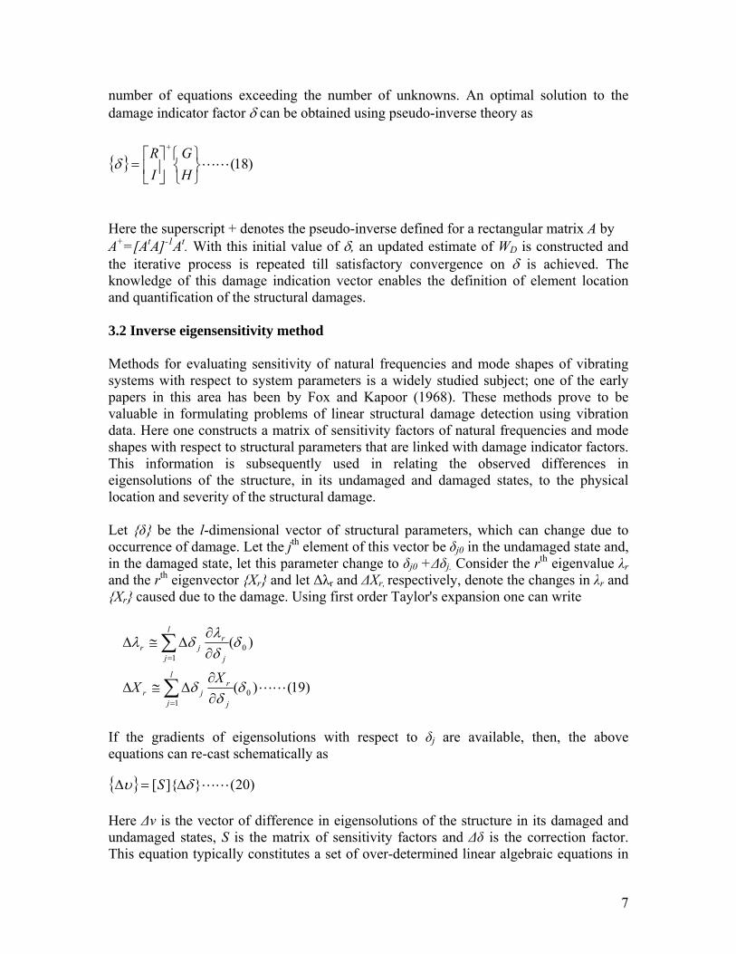
ber of equations exceedingage indicator factor δ
Here the superscript + denotes the pseudo-inverse defined for a rectangular matrix A by A+=[AtA]-1At. With this initial value of δ, an updated estimate of WD is constructed and the iterative process is repeated till satisfactory convergence on δ is achieved. The
)18(LL⎭⎬⎫
⎩⎨⎧
⎥⎦
⎤⎢⎣
⎡=
+
HG
IR
δ
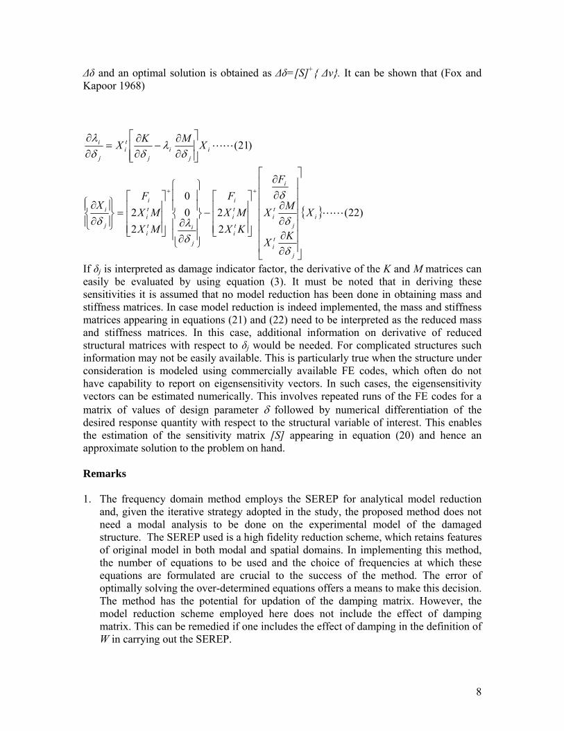
kand quantification of the structural dam 3.2 Inverse eigensensi Msystems with respect to system parameters is a widely studied subject; one of the earlypapers in this area has been by Fox and Kapoor (1968). These methods prove to be valuable in formulating problems of linear structural damage detection using vibration data. Here one constructs a matrix of sensitivity factors of natural frequencies and mode shapes with respect to structural parameters thTeigensolutions of the structure, in its lo Let δ be the l-dimensional vector of structural parameters, which can change due to occurrence of damage. Let the jth element of this vector be δj0 in the undamaged state and, in the damaged state, let this parameter change to δj0 +∆δj. Consider the rth eigenvalue λr and the rth eigenvector Xr and let ∆λr and ∆Xr, respectively, denote the changes in λr and Xr caused due to the damage. Using first order Taylor's expansion one can write
)( 01
δδλ
δλ ∑= ∂
∂∆≅∆
l
j j
rjr
)19()( 01
LLδδ
δ∑= ∂
∂∆≅∆
l
j j
rjr
XX
If the gradients of eigensolutions with respect to δj are available, then, the above quations can re-cast schematically as e
)20(][ LLδυ ∆=∆ S
Here ∆ν is the vector of differenundamaged states, S is the matrix oThis equation typically constitu
7
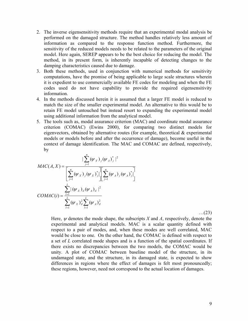
∆δ and an optimal solution is obtained as ∆δ=[S]+ ∆ν. It can be shown that (Fox and
Kapoor 1968)
)22(220
0
2
i
ti
j
FF
X
F ⎥⎥⎤
⎢⎢⎡
∂∂
⎤⎡⎪⎫
⎪⎧
⎤
⎢⎣
⎡
⎪⎭⎪⎩
++ δ2 LLi
j
ti
j
ti
ti
ti
i
i
ti
ii X
KX
MXKXMX
MMX
X
⎥⎥⎥⎥⎥
⎦⎢⎢⎢⎢⎢
⎣ ∂∂∂∂
⎥⎥⎥
⎦⎢⎢⎢
⎣
−
⎪⎪
⎭
⎪⎬
⎪⎪
⎩
⎪⎨
∂∂⎥
⎥⎥
⎦⎢⎢=⎪⎬
⎫⎧∂
δ
δδλδ
If δj is interpreted as damage indicator factor, the derivative of the K and M matrices can asily be evaluated by using equation (3). It must be noted that in deriving these nsitivities it is assumed that no model reduction has been done in obtaining mass and
stiffness matrices. In case model reduction is indeed implemented, the mass and stiffness matrices appearing in equations (21) and (22) need to be interpreted as the reduced mass and stiffness matrices. In this case, additional information on derivative of reduced structural matrices with respect to δj would be needed. For complicated structures such information may not be easily available. This is particularly true when the structure under consideration is modeled using commercially available FE codes, which often do not have capability to report on eigensensitivity vectors. In such cases, the eigensensitivity
ethod. The error of optimally solving the over-determined equations offers a means to make this decision.
ethod has the potential for updation of the damping matrix. However, the model reduction scheme employed here does not include the effect of damping
j
⎪⎨∂
ese
vectors can be estimated numerically. This involves repeated runs of the FE codes for a matrix of values of design parameter δ followed by numerical differentiation of the desired response quantity with respect to the structural variable of interest. This enables the estimation of the sensitivity matrix [S] appearing in equation (20) and hence an approximate solution to the problem on hand. Remarks 1. The frequency domain method employs the SEREP for analytical model reduction
and, given the iterative strategy adopted in the study, the proposed method does not need a modal analysis to be done on the experimental model of the damaged structure. The SEREP used is a high fidelity reduction scheme, which retains features of original model in both modal and spatial domains. In implementing this method, the number of equations to be used and the choice of frequencies at which these equations are formulated are crucial to the success of the m
The m
matrix. This can be remedied if one includes the effect of damping in the definition of W in carrying out the SEREP.
)21(LLij
ij
ti
j
i XX⎥⎥⎦⎢
⎢⎣ ∂
−∂
=∂ δ
λδδ
MK ⎤⎡ ∂∂λ∂
8
2.
3. e of being applicable to large scale structures wherein
4.
model.
age identification. The MAC and COMAC are defined, respectively,
The inverse eigensensitivity methods require that an experimental modal analysis be performed on the damaged structure. The method handles relatively less amount of information as compared to the response function method. Furthermore, the sensitivity of the reduced models needs to be related to the parameters of the original model. Here again, SEREP appears to be the best choice for reducing the model. The method, in its present form, is inherently incapable of detecting changes to the damping characteristics caused due to damage. Both these methods, used in conjunction with numerical methods for sensitivity computations, have the promisit is expedient to use commercially available FE codes for modeling and when the FE codes used do not have capability to provide the required eigensensitivity information. In the methods discussed herein it is assumed that a larger FE model is reduced to match the size of the smaller experimental model. An alternative to this would be to retain FE model untouched but instead resort to expanding the experimental model using additional information from the analytical
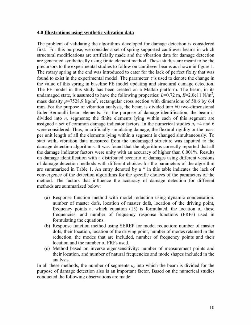
5. The tools such as, modal assurance criterion (MAC) and coordinate modal assurance criterion (COMAC) (Ewins 2000), for comparing two distinct models for eigenvectors, obtained by alternative routes (for example, theoretical & experimental models or models before and after the occurrence of damage), become useful in the context of damby
∑∑
∑
∑∑
=
==
=
⎥⎦
⎤⎢⎣
⎡⎥⎦
⎤⎢⎣
⎡
LL
ilA
L
lilX
n
jjAjA
n
jjXjX
iMAC
2
1
1
*
1
*
|)()(|)(
)()()()(
ψψ
ψψψψ
∑==
n
jjAjX
XAC
2
1
* |)()(|),(
ψψ
== lilA
lilX
CO
MA
1
2
1
2 )()( ψψ
…(23) Here, ψ denotes the mode shape, the subscripts X and A, respectively, denote the experimental and analytical models. MAC is a scalar quantity defined with respect to a pair of modes, and, when thes well correlated, MAC would be close to one. On the other hand, the COMAC is defined with respect to a set of L correlated mode shapes and is a function of the spatial coordinates. If there exists no discrepancies between the two models, the COMAC would be unity. A plot of COMAC between baseline model of the structure, in its undamaged state, and the structure, in its damaged state, is expected to show differences in regions where the effect of damages is felt most pronou
e modes are
ncedly; these regions, however, need not correspond to the actual location of damages.
9
4.0 Illustrations using synthetic vibration data
blem of validating the algorithms developed for damage detection is considered or this purpose, we consider a set of spring supported cantilever beams in which al modifications are artificially made and the vibration data for damage detection erated synthetically using finite element method. These studies are meant to be t
The profirst. Fstructurare gen he
recursors to the experimental studies to follow on cantilever beams as shown in figure 1. The rotary spring at the end was introduced to cater for the lack of perfect fixity that was found to exist in the experimental model. The parameter τ is used to denote the change in the value of this spring in baseline FE model updating and structural damage detection. The FE model in this study has been created on a Matlab platform. The beam, in its undamaged state, is assumed to have the following properties: L=0.72 m, E=2.0e11 N/m2, mass density ρ=7528.9 kg/m3, rectangular cross section with dimensions of 50.6 by 6.4 mm. For the purpose of vibration analysis, the beam is divided into 60 two-dimensional Euler-Bernoulli beam elements. For the purpose of damage identification, the beam is divided into ns segments; the finite elements lying within each of this segment are assigned a set of common damage indicator factors. In the numerical studies ns =4 and 6 were considered. Thus, in artificially simulating damage, the flexural rigidity or the mass per unit length of all the elements lying within a segment is changed simultaneously. To start with, vibration data measured from the undamaged structure was inputted to the damage detection algorithms. It was found that the algorithms correctly reported that all the damage indicator factors were unity with an accuracy of higher than 0.001%. Results on damage identification with a distributed scenario of damages using different versions of damage detection methods with different choices for the parameters of the algorithm are summarized in Table 1. An entry denoted by a * in this table indicates the lack of convergence of the detection algorithms for the specific choices of the parameters of the method. The factors that influence the accuracy of damage detection for different methods are summarized below:
(a) Response function method with model reduction using dynamic condensation: number of master dofs, location of master dofs, location of the driving point, frequency points at which equation (15) is formulated, the location of these frequencies, and number of frequency response functions (FRFs) used in formulating the equations.
(b) Response function method using SEREP for model reduction: number of master dofs, their location, location of the driving point, number of modes retained in the reduction, the modes that are included, number of frequency points and their location and the number of FRFs used.
(c) Method based on inverse eigensensitivity: number of measurement points and their location, and number of natural frequencies and mode shapes included in the analysis.
In all these methods, the number of segments ns into which the beam is divided for the purpose of damage detection also is an important factor. Based on the numerical studies conducted the following observations are made:
p
10
(i) The treatment of rotational dofs as slaves does not affect the success of the damage detection algorithms.
.0 Experimental studies
(ii) In the response function method, with fewer translation dofs treated as masters, the accuracy of the method deteriorates; in some instances, the algorithms failed to converge. The method based on inverse eigensensitivity showed convergent behavior but with increasing errors with reduction in number of masters. In fact with only one master and with information on six eigenvalues, the method converged and could detect damages with accuracy varying from 0.38% to 11.7% depending upon the specific choice of the master dof made.
(iii) The response function method using dynamic condensation was found to be computationally more intensive as compared with the method based on SEREP. When only four masters were selected, the method based on SEREP failed to provide convergent solutions while the method based on dynamic condensation continued to perform well.
(iv) In the response function method, with dynamic condensation for model reduction, the set of discrete frequencies that are included in the analysis plays a crucial role. The accuracy does not necessarily improve, as this set is made large. The inclusion of about three frequencies around each resonant peak was found to lead to acceptable convergent behavior of the damage detection algorithm. A similar observation has been made in the existing literature by Rad (1997) in the context of FE model updating.
(v) The method based on inverse eigensensitivity was found to be the most robust among the three methods studied with respect to variations in number of masters, choices of master dofs and number of segments made for damage detection.
(vi) The number of iteration cycles, when convergent solutions were possible, varied from about 3 to 4 for the inverse eigensensitivity method and up to about 15 iterations for the response function method.
5 5.1 Stu The exp(50.6 b a heavy cast iron block at one end (figure 1). The Yothe analength wrotation he beam was divided into 6 segments and all spatial rFor the ing at the end a preliminary value of Kθ=10000 Nm/rad was assigned.
and after updating, the experimentally easured natural frequencies on damaged and undamaged beams and the natural
frequencies predicted after damage detection was completed. The updating and damage
dies on cantilever beams
erimental set up consists of a steel beam 0.72 m long, of rectangular cross-section y 6.4 mm) and bolted to
ung’s modulus was found to be 2.0e+11 N/m2 and mass density of 7528.9 kg/m3. In lytical model development the beam was divided into 60 finite elements of equal
ith a rotary spring inserted at the clamped end to model any lack of fixity against . For the purpose of damage detection, t
the finite elements lying within a segment were assigned the same properties. Thus the esolution of the damage detection in this case is equal to 1/ 6th of the beam span.
rotary sprAn updating exercise based on the method of inverse eigensensitivity was conducted and the results are summarized in Tables 2 and 3. Table 2 shows the summary of results on natural frequencies of the baseline model beforem
11
detection were based on method of inverse eigensensitivity with first six natural cies and mode shapes. It mayfrequen be noted that for the purpose of simulation of a
agsupportdependbe obsethis malocationmay be espond to scheme III
data onplacemdamagedampin ready reference. The success of the baseline model
in TablFigure shape ftoward In the FRFs were measured by using impulse hammer tests. In
near thtype 82
using sbased, 00 data acquisition system equipped with an anti-aliasing filter (with cut-off frequency of 1000 Hz) and a simultaneous
sampling rate of 4000/s was used in conjunction with a ctangular window (of width 0.05 s) for the hammer blow and an exponential window
responses. In Each measurement data of duration 8.192 was acquired. The FRFs were averaged over 30 samples. A worksheet to conduct the
“dam e” a concentrated mass of 0.027 kg was placed at a distance of 0.32 m from the . It was found that the accuracy with which the damage was identified was ent on the scheme adopted for placement of sensors (figure 1 and Table 4). As can rved from the results presented in Table 4, the damage detection algorithm locates ss with accuracy varying from about 0.15% to 5 % depending upon the sensor scheme. Thus, for scheme 3 the highest error was found to be less than 1.6%. It
noted that the results shown in Tables 2,3,5 and 6 and 4 corrof sensor placement. It is of importance note in this context that analyses using synthetic
this system provided equally acceptable results for all the three schemes of sensor ents. Table 5 summarizes the MAC values between experimental observations on d and undamaged structures; the values of the natural frequencies and modal g are also provided here for
updation as well as damage detection can be discerned from COMAC values summarized e 6 in which it can be seen that the COMAC value is close to unity at all the dofs. 4 illustrates the experimentally measured and analytically predicted 3rd mode or the damaged beam. The close agreement found between these plots again points s the success of the damage detection process.
experimental work the order to achieve acceptable quality of input pulse, it was found advantageous to select
e beam support to impart the hammer blows. For this purpose the B&K hammer 02 with plastic tip, B&K 8200 force transducer and B&K 2635 charge amplifier
was used. The acceleration response of the beam was measured at a set of six points by train gauge based Sensotech accelerometers. The data was acquired using a PC 4-channel 100kHz IOTECH DAQ Board/20
sampling and hold board. Are[w(t)=exp(-t/0.659)] for the beam s experiment was created on a DASYLab platform. The extraction of modal information from the measured vector of FRFs was carried using the ME’scope software using polynomial curve fitting method with due correction being made for the artificial attenuation effect arising due to the use of exponential window. It may be noted that each of the accelerometers used had a mass of 0.012 kg and these masses were added to the FE model developed for the purpose of damage detection. 5.2 Studies on a three-storied building frame model Figure 5 shows the model of a three storied, single bay building frame. The columns were made flexible in one direction and slabs were heavier and much more rigid than the columns: this ensured that the structure would behave predominantly as a three-dof shear beam. A three-dof model for the frame was thus made and updated using experimentally measured eigenparameters in conjunction with the inverse eigensensitivity method of
12
updating. A modification to the structure was artificially simulated by adding a mass of 0.233 kg to the second floor. Table 7 summarizes the results on natural frequencies for the initial assumed model, experimental results on damaged structure, updated baseline model and the predicted values from damaged structure after damage has been analytically detected. Tables 8 and 9 summarize the results on baseline model updating and detection of damage in the modified structure. The results on MAC and COMAC are summarized for the cases of updating of baseline model and for assessment of efficacy of damage detection. As can be observed from Table 9, the damage detection here has been possible with the highest error being less than 3%. The measurement of eigenparameters of the system was based on impulse hammer method and the details of the measurement strategy used was broadly similar to the one followed for the beam structure. 6.0 Closing remarks The problem of structural damage identification using vibration data in cantilever beam structures and a three-storied shear-building frame is considered. Methods based on FE model updating are employed to detect, locate and quantify the damages. This has involved the application of response function and inverse eigensensitivity methods for element level location and quantification of structural damages. The governing equations
r the damage indication factors in both of these methods are shown to constitute a set of
(such as, loss of stiffness, changes damping and/or onset of nonlinear behavior).
foover determined coupled nonlinear equations. The nonlinear nature of these equations essentially arises due to the spatial incompleteness of the experimental data. These equations are solved using an iterative strategy. The study has involved both synthetic and experimentally produced data. The studies on using synthetic data have proved to be useful in investigating the range of validity of the damage identification schemes vis-à-vis the choices made on number of masters and their location, number of modes retained in the reduced models obtained using SEREP, and number and location of frequency points in reduction method involving dynamic condensation. The convergence and accuracy of the iterative strategy used in damage identification are shown to be dependent on these choices. Additionally, in the studies involving experimental data, the accuracy of damage identification is observed to be strongly influenced by the location of sensors and the drive point. For a given structural damage configuration, analyses using synthetic data provided equally acceptable results for alternative schemes of sensor placement while the damage identification using experimental studies showed significantly varying error patterns. Further studies are needed to explain these patterns of errors observed in damage identification using experimental data. Similarly, the scope of the present study needs to be expanded to include the treatment of measurement noise, more general forms of structural modification due to occurrence of damage in Acknowledgement This work has been conducted as a part of a research project entitled “Structural damage detection using vibration data and probabilistic structural health monitoring”, funded by the CSIR, Government of India. The authors are thankful for the support received.
13

References
1. J O Callahan, P Avitable, and R Riemer, 1989, System equivalent reduction expansion process (SEREP), Proceedings of the 7th International Modal Analysis Conference, Las Vegas, Nevada, February, 29-37.
2. S W Doebling, C R Farrar, M B Prime, D W Shevitz, 1996, Damage identification and health monitoring of structural and mechanical systems from changes in their vibration characteristics; A literature review, Los Alamos LA-13070-MS, UC-900, Los Alamos National Laboratory.
3. S W Doebling, C R Farrar, M B Prime, 1998, A summary Review of vibration-based damage identification methods, Shock and Vibration Digest, 30(2), 91-105.
odal testing: Theory, Practice and Application, Research studies press limited. Baldock, Hertfordshire 2000.
amage through changes in frequency: a review, Engineering Structures, 19(9), 718-723.
15. W J Staszewski, 1998, Structural and mechanical damage detection using Shock and Vibration Digest, 30(6), 457-472.
4. D J Ewins, M
5. C R Farrar, W Scott, S W Doebling, A N David, 2001, Vibration-based structural damage identification, Philosophical Transactions of Royal Society, London, 359, 131 149.
6. C R Farrar, S W Doebling, 1999, Damage detection and evaluation II, A chapter in Modal analysis and Testing, J M M Silva and N M M Maia (Eds.), Kluwer Academic Publishers, Dordrecht, 345-378.
7. R L Fox and M P Kapoor, 1968, Rates of change of eigenvalues and eigenvectors, AIAA Journal, 6, 2426-2429.
8. M I Friswell and J E Mottershead, 1996, Finite element model updating in structural dynamics, Kluwer Academic Publishers, Dordrecht.
9. J He, 1999, Damage detection and evaluation I, A chapter in Modal analysis and Testing, J M M Silva and N M M Maia (Eds.), Kluwer Academic Publishers, Dordrecht, 325-344.
10. K G McConnel, 1995, Vibration testing: theory and practice, John Wiley, New York.
11. L Majumder and C S Manohar, 2003, A time domain approach for damage detection in beam structures using vibration data with a moving oscillator as an excitation source, Journal of Sound and Vibration, 268, 699-716.
12. L Majumder and C S Manohar, 2004, Nonlinear reduced models for beam damage detection using data on moving oscillator-beam interactions, Computers and Structures, 82(2-3), 301-314.
13. S Z Rad, 1997, Methods for updating numerical models in structural dynamics, PhD thesis, Imperial College of Science, Technology and Medicine, University of London.
14. S Salawu, 1997, Detection of structural d
wavelets, The
14
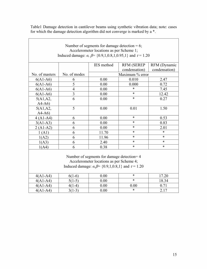
Table1 Damage detection in cantilever beams using synthetic vibration data; note: cases damage detection algorithm did not converge is marked by a *.
eme 1;
for which the
Number of segments for damage detection = 6; Accelerometer locations as per Sch
Induced damage: α, β= 0.9,1,0.8,1,0.95,1 and τ = 1.20
IES method RFM (SEREP condensatio
RFM (Dynamic n) condensation)
No. of masters No. of modes Maximum % error 6(A1-A6) 6 0.00 0.010 2.47 6(A1-A6) 5 0.00 0.000 0.72 6(A * 7.45 1-A6) 4 0.00 6(A1-A6) 3 0.00 * 12.42 5(A1,A2,
-A6) 6 0.00 * 0.27
A45(A1,A2,
-A6) 5 0.00 0.01 1.50
A44 (A1-A4) 6 0.00 * 0.53 3(A1-A3) 6 0.00 * 0.83 2 (A1-A2) 6 0.00 * 2.01
1 A1) 6 11.70 * * (1(A2) 6 11.96 * * 1(A3) 6 2.40 * * 1(A4) 6 0.38 * *
Number of segments for damage detection= 4
Accelerometer locations as per Scheme 4; Induced damage: α,β= 0.9,1,0.8,1 and τ = 1.20
4(A1-A4) 6(1-6) 0.00 * 17.20 4(A1-A4) 5(1-5) 0.00 * 18.34 4(A 0.00 0.00 0.71 1-A4) 4(1-4) 4(A1-A4) 3(1-3) 0.00 * 2.17
15
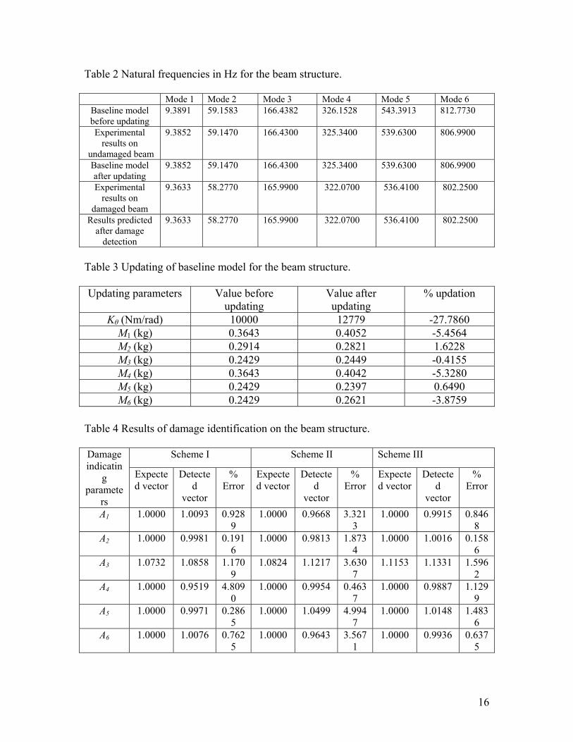
Table 2 Natural frequencies in Hz for the beam structure.
Mode 1 Mode 2 Mode 3 Mode 4 Mode 5 Mode 6 Baseline model before updating
9.3891 59.1583 166.4382 326.1528 543.3913 812.7730
Experimental results on
undamaged beam
9.38 300 806.9900 52 39.659.1470 166.4300 325.3400 5
Baseline model after u ing
9.3852 59.1470 166.4 0 325.3400 539.6300 806.9900 pdat
30
Experi ental 9.3633 8.2770 322 00mresults on
damaged beam
5 165.9900 .0700 536.41 802.2500
Re d a
9.3633 8.2770 165 322.070 36.4100 00 sults predictefter damage detection
5 .9900 0 5 802.25
Table 3 Updating of baseline model for the beam structure. Updating parameters Value before
updating Value aupdati
% updation fter ng
Kθ (Nm/rad) 10000 12779 -27.7860 M1 (kg) 0.3643 0.4052 -5.4564 M2 (kg) 0.2914 0.2821 1.6228 M3 (kg) 0.2429 0.2449 -0.4155 M4 (kg) 0.3643 0.4042 -5.3280 M5 (kg) 0.2429 0.2397 0.6490 M6 (kg) 0.2429 0.2621 -3.8759
Table 4 Results of da
S e III
mage identification on the beam structure.
cheme I Scheme II SchemDamage indicatin
parExpecte
ector Detecte
v
% Error
Expectd ve
Detected
vector
% Error
Expected vector
Detected
vec
% rror
g amete d vrs
d ector
ector E
tor Α1 1.0000 1. 8
9 1.00 0.9668 3.32
3 .0000 0.99 6
8 0093 0.92 00 1 1 15 0.84
Α2 1.0000 0.9981 0.1916
1.0000 0.9813 1.8734
1.0000 1.0016 0.1586
Α3 1.0732 1.0858 1.1709
1.0824 1.1217 3.6307
1.1153 1.1331 1.5962
Α4 1.0000 0.9519 4.8090
1.0000 0.9954 0.4637
1.0000 0.9887 1.1299
Α5 1.0000 0.9971 0.2865
1.0000 1.0499 4.9947
1.0000 1.0148 1.4836
Α6 1.0000 1.0076 0.7625
1.0000 0.9643 3.5671
1.0000 0.9936 0.6375
16
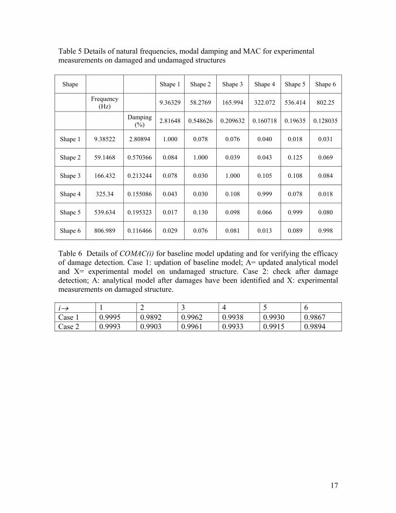
Table 5 Details of natural frequencies, modal damping and MAC for experimental easurements on damaged and undamaged structures
Shape 1 Shape 2 Shape 3 Shape 4 Shape 5 Shape 6
m
Shape
(Hz)Frequency
9.36329 58.2769 165.994 322.072 536.414 802.25
mp(%) 2.81648 0.548626 0.209632 0.160718 0.19635 0.128035 Da ing
Sha 522 2.80894 1.000 0.078 0.076 0.040 0.018 0.031 pe 1 9.38
Shape 2 59.1468 03 084 1. 0.04 125 0.0.57 66 0. 000 0.039 3 0. 069
Shape 3 166.432 0.213244 0.078 0. 0 1.000 0.105 0.108 0.084 03
Shape 4 325.34 0.155086 0.043 0.030 0.108 0.999 0.078 0.018
Shape 5 539.634 0.195323 0.130 0 066 0.999 0.080 0.017 .098 0.
Shape 6 89 0.116466 0.076 0. 0.013 0.08 98 806.9 0.029 081 9 0.9
Table 6 Details of COMAC(i) for baseline model updating and for verifying the efficacy of dam tion. Case 1: updation of baseline model; A= updated analytical model and X= experimental model on undamaged structure. Case 2: check after damage detecti alytical model after damage have be fied and X: ntal measurements on damaged structure.
→ 1 2 3 4 5 6
ag detece
on; A: an s en identi experime
i Case 1 0.9995 0.9892 0.9962 0.9938 0.9930 0.9867 Case 2 0.9993 90 933 940.9 3 0.9961 0.9 0.9915 0.98
17

Table 7 Natural frequencies in Hz for the frame structure.
Mode 1 Mode 2 Mode 3 Baseline mbefor
odel e upda g
2.8495 7.9650 tin
11.4742
Experimeon undam
frame
2.7931 7.9084 ntal results aged
11.6370
Results from he updated baseline
od
2. 7 t
m el
7931 7.9084 11.63 0
Experimental results ag
2.7306 7.8676 11.2670 on dam ed frame Results predicted
dadetection
2.7306 7.8676 11.2670 after mage
Up f t e for ame ure.
g p rs alu re updating
Value after updating pda
Table 8 dating o he baselin model the fr struct
Updatin aramete V e befo % u tion
M1 (kg) 1.9430 1.8846 3.0063 M2 (kg) 1.9430 1.8449 5.0510 M3 (kg) 1.8938 2.1107 -11.4544
Table 9 Results on the damage detection for the frame structure.
mage indicating
ramexpected ve r Detected vecto % Error Da
pa ters E cto r
α1 000 2 1.9847 1.0 0.980α2 1.1182 1.1508 -2.9132 α3 1.0000 0.9999 0.0094
18
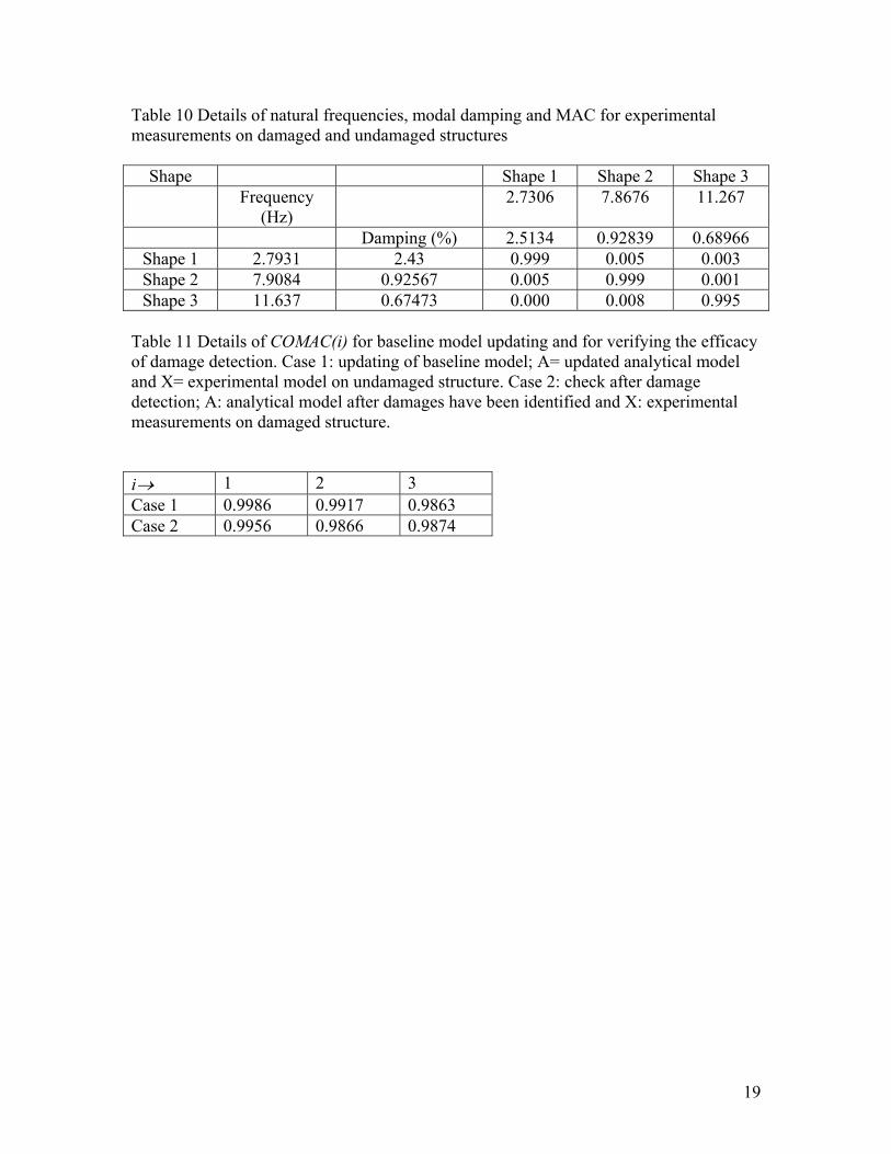
Table 10 Details of natural frequencies, modal damping and MAC for experimental measurements on damaged and undamaged structures
Shape 2 e 3 Shape Shape 1 Shap Frequency
) 2.7306 7.8676 11.267
(Hz Damping (%) 2.5134 0.92839 0.68966
Shape 2.7931 2.43 0.999 0.005 0.003 1 Shape 2 7.9084 2567 0.999 01 0.9 0.005 0.0Shape 3 11.637 0.67473 0.000 0.008 0.995
MAC( eline model up nd for verifyi acy
o Case 1: updating of baseline model; A= updated analytical model a l model on undamaged structure check after ddete tical model after damages have been identified and X: experimental meas n damaged structure.
Table 11 Details of COf damage detection.
i) for bas dating a ng the effic
nd X= experimentaction; A: analyurements o
. Case 2: amage
i→ 1 2 3 Case 1 0.9986 0.9917 0.9863 Case 2 0.9956 0.9 74 866 0.98
19

SCHEME L1 L2 L3 L4 L5 L6 Lm
1
M: Mass (Structural modification)F: Excitation (Impulse hammer)
A1-A6: Accelerometers
120 120 160 80 120 120 320
2 140 110 140 110 110 110 320
3 150 120 100 150 100 100 320
L3L2L1
Kt: Torsion spring
Lm
A1 M
F
A2
L5L4 L6
All dimensions in mm
A6A
4 200 160 160 - - -
A3 A4 5
200
Figure 1 Details of experimental setup for studies on cantilever beam.
20
-200 -150 -100 -50 0 50 100 150 2000
50
100
150
200
250
300
350
400
Real,(m/s/s)/N
Imag
inar
y,(m
/s/s
)/Ndamagedundamaged
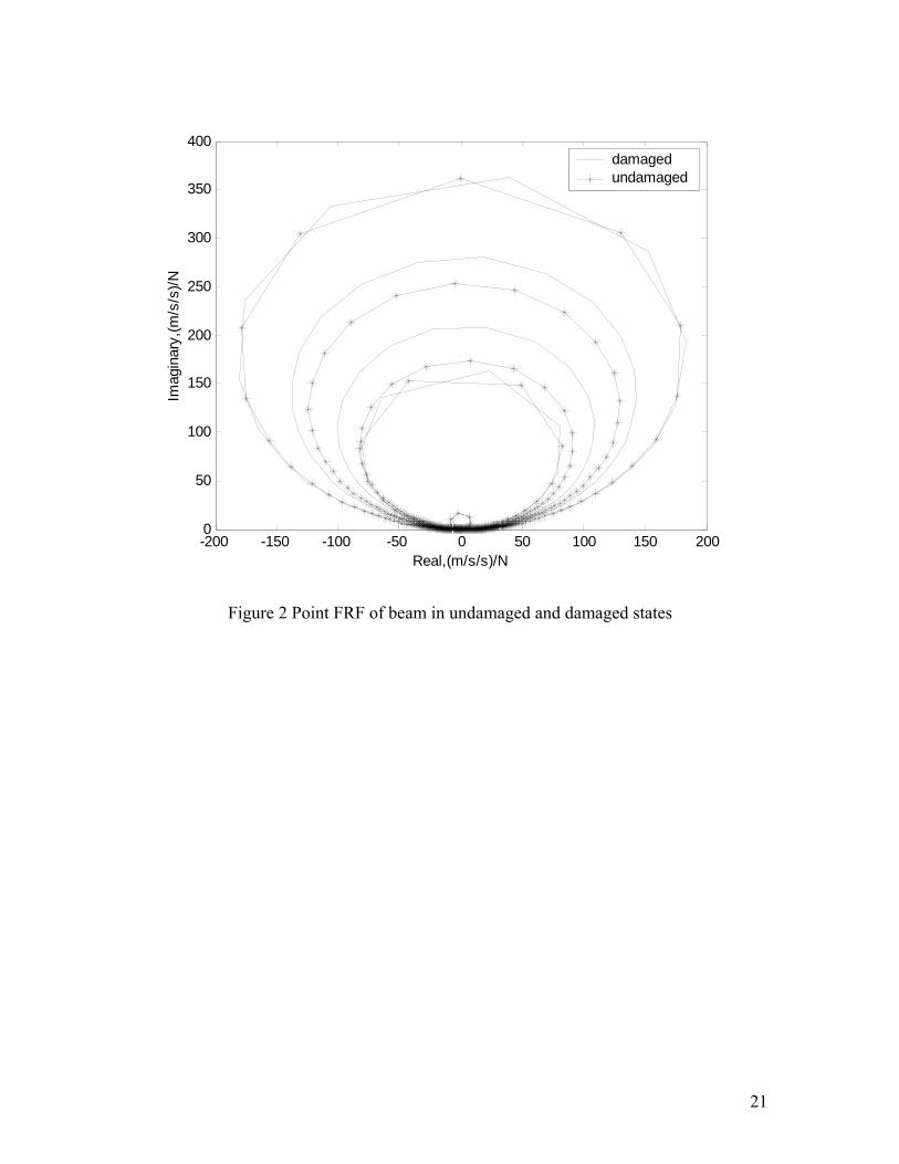
Figure 2 Point FRF of beam in undamaged and damaged states
21
-200 -150 -100 -50 0 50 100 150 2000
50
100
150
200
250
300
350
400
Real,(m/s/s)/N
Imag
inar
y,(m
/s/s
)/Ndamagedpredicted
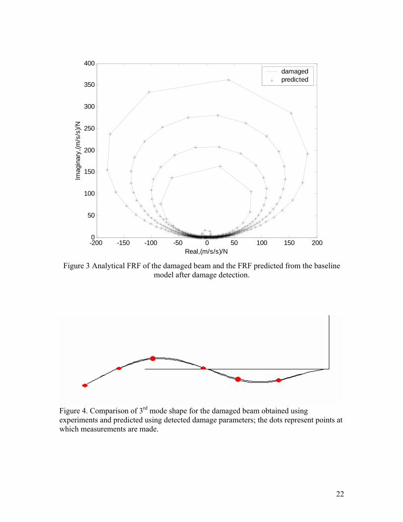
Figure 3 Analytical FRF of the damaged beam and the FRF predicted from the baseline
model after damage detection.
rdFigure 4. Comparison of 3 mode shape for the damaged beam obtained using
experiments and predicted using detected damage parameters; the dots represent points at which measurements are made.
22
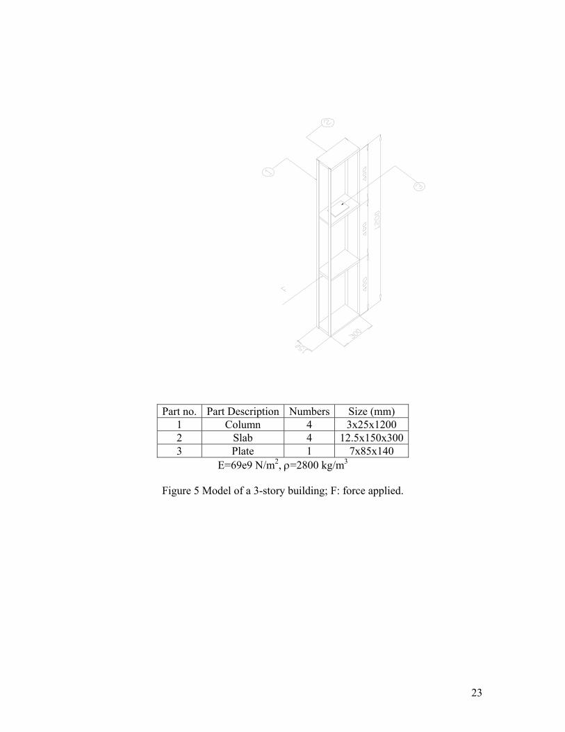
Part no. Part Description Numbers Size (mm) 1 Column 4 3x25x1200 2 Slab 4 12.5x150x300 3 Plate 1 7x85x140
E=69e9 N/m2, ρ=2800 kg/m3
Figure 5 Model of a 3-story building; F: force applied.
23